1
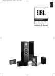
®
™
STUDIO L SERIES
L810, L820, L830, L880,
L890, LC1, LC2
OWNER’S GUIDE
SPEAKER PLACEMENT
Proper placement of the
speakers is an important step
in obtaining the most realistic
soundstage possible. These
recommendations are for the
optimum placement of the
loudspeakers. Use these
placement recommendations
as a guide. Slight variations
will not diminish your listening
pleasure.
All of the Studio L Series
loudspeakers referred to in
this guide are video-shielded
and may safely be placed
near a television.
MODELS: L830, L880, L890
MODELS: L810 AND L830
As front speakers
As surround speakers
1.5m–1.8m
(5–6 ft.)
2
English
MODEL: L820
The L820 loudspeakers are
designed to be oriented
horizontally, as shown in the
illustrations below. Although
these loudspeakers are
designed as a mirrored pair,
the decision as to which one
is left or right will depend on
the amount of space left
between them.
For stereo-only applications:
A wider stereo image is
presented with the tweeter/
midrange array outboard, and
a tighter image is presented
with the array inboard.
Less than 1,8m-2,4m
(6-8 feet)
Less than 1,8m-2,4m
(6-8 feet)
For home theater applications:
0-0,6m
(0-2ft)
This placement provides a
wide spread in sound,
supplemented by the center
channel speaker.
MODELS: LC1, LC2
The LC1 and LC2 center
channel loudspeakers are
designed to complement all of
the Studio L Series loudspeakers. Either speaker is
ideal for re-creating the
cinematic experience in your
home.
3
SPEAKER CONNECTIONS
MODELS: L810,
L820, L830, L880,
L890
Right
Left
RIGHT
LEFT
–
+
–
– +
–
Right
RIGHT
Left
LEFT
+
+
Receiver’s Speaker Outputs
MODELS: LC1,
LC2
Center
–
+
–
+
Center
Receiver’s Speaker Outputs
Speakers and electronics
have corresponding (+) and
(–) terminals. It is important to
connect both speakers
identically: (+) on the speaker
to (+) on the amplifier and (–)
on the speaker to (–) on the
amplifier. Wiring “out of
phase” results in thin sound,
weak bass and poor imaging.
To use the binding-post
speaker terminals, unscrew
the colored collar until the
pass-through hole in the
center post is visible. Insert
the bare end of the wire
through this hole; then screw
the collar down until the
connection is tight.
The hole in the center of each
collar is intended for use with
banana-type connectors. To
comply with European CE
certification, these holes are
blocked with plastic inserts at
the point of manufacture. To
use banana-type connectors
requires the removal of the
inserts. Do not remove these
inserts if you are using the
product in an area covered by
the European CE certification.
BI-WIRING
The bi-wire connection
method requires one amplifier
and two sets of speaker wires.
By removing the shorting
bars, connections may be
made to the individual network
sections using four conductors,
one for each of the four
terminals.
For single-wire connection,
leave the shorting bars in
place and connect only a
single set of speaker wires
(two conductors) to the two
upper terminals.
HighFrequency
Frequency
High
–
+
–
+
Low Frequency
–
+
Amplifier
Amplifier
Bi-Wire Connections
SPEAKER SETUP
MODELS: L810,
L820, L830, LC1,
LC2
The supplied self-adhesive
rubber feet may be attached to
the bottom corners of your
speakers to protect your
furniture.
Placepads
pads here
Place
here
4
MODELS: L880,
L890
These models feature four
rubber feet that enable them
to be placed on a smoothsurfaced floor, such as tile or
hardwood. Four metal spikes
are supplied for use when the
speaker is to be placed on a
carpeted surface, to decouple
the speaker from the floor and
prevent unwanted damping.
To insert the spikes, gently lay
the speaker on its side (not its
front or back) on a soft,
nonabrasive surface. Each
spike screws into the threaded
insert in the center of each
rubber foot. Make sure all
four spikes are screwed in
completely for stability.
NEVER drag the speaker to
move it, as this will damage
the spikes, the feet and/or the
wood cabinet itself. Always
lift the speaker and carry it to
its new location.
positioned. If this is a concern,
these speakers should be
anchored to the wall behind
them, using the same
procedures and hardware
customary for anchoring
bookcases and wall units. The
customer is responsible for
proper installation and proper
selection of hardware.
WALL-MOUNTING
(Models L810, L820,
LC2)
Important Safety Notes
• Proper selection of mounting
hardware and installation of
the wall brackets are the
responsibility of the customer.
• This product is not intended
for ceiling mounting.
with your loudspeaker that
indicates the proper locations
for the pilot holes. In the event
that the template is missing,
refer to this chart:
Model
Distance Between
Pilot Holes
L810
152mm (6")
L820
216mm (8-1/2")
Two Number 8 round-head or
pan-head screws should be
used for each loudspeaker.
The screw head should be
between 5/16 inch (8mm) and
1/4 inch (6.3mm) in diameter,
and the screw should be at
least 2 inches (50mm) in
length.
LC2
368mm (14-1/2")
When installing screws in any
wall, it is always preferable to
screw them into a wall stud. If
none is available, it is
important to always use
properly selected wall
anchors.
Install the two screws into
either a wooden wall stud or
anchor, and tighten them until
the back of each screw head
is about 1/8" (3mm) from the
wall. See Figure 2.
Attach two of the four selfadhesive rubber pads that
came with the loudspeaker to
the back of the enclosure in
the two bottom corners so
that the cabinet is spaced
evenly from the wall. Select a
suitable mounting location on
a wall. (The ceiling is not a
suitable mounting location.)
Drill two pilot holes,
appropriately sized for the
specific self-tapping screw or
wall anchor that you will be
using. A template is included
See Figure 1. The holes
should be 57mm below where
you want the top of the
enclosure to be positioned.
Use a carpenter’s level to
ensure that the holes are
even and that the speaker will
mount on the level.
Models L810 and L820 may
also be corner-mounted using
the keyholes located on the
bezeled corners. For corner
mounting, fold the mounting
template in half, place the fold
in the corner at the desired
height, and use the outer
holes. In case the template is
missing, for corner mounting
drill each pilot hole 7-3/4"
(197mm) from the corner for
model L810, or 9-11/16"
(246mm) from the corner for
model L820. However, if your
corner is not precisely 90
degrees, these measurements
may not work. In that case, it
is recommended that you
contact a professional custom
installer, who can determine
the correct locations for the
pilot holes. Install the
loudspeaker by slowly moving
the cabinet toward the
screws so that the screw
heads clear the larger
circular portion of the two
keyholes. Once both screw
heads have entered the
keyholes, the loudspeaker
should gently be lowered onto
the screw shafts. Check that
the loudspeaker is firmly
locked onto the screws by
gently pulling the speaker
down and forward.
See Chart
See
Chart
Fig. 1
3mm
(1/8")
Fig. 2
5
English
CAUTION: Floorstanding
(tower) loudspeakers have a
high center of gravity and may
become unstable and tip over
during earthquakes, or if
rocked, tipped or improperly
SPECIFICATIONS
L810
L820
L830
L880
Description
3-Way, 5-1/4" Bookshelf/
Wall-Mount Satellite
4-Way, 6" HighPerformance,
Mirror-Image,
Wall-Mount Satellite
3-Way, 6" Bookshelf
4-Way, Dual 6"
Floorstanding
Maximum
Recommended
Amplifier Power
150W
150W
150W
200W
Power Handling
(Continuous/Peak)
75W/300W
75W/300W
75W/300W
100W/400W
Nominal Impedance
8 Ohms
8 Ohms
8 Ohms
8 Ohms
Sensitivity (2.83V/1m)
88dB
90dB
90dB
91dB
Frequency
Response (±3dB)
60Hz – 40kHz
55Hz – 40kHz
48Hz – 40kHz
30Hz – 40kHz
Crossover
Frequencies
3500Hz, 20kHz
600Hz, 3500Hz, 20kHz
2500Hz, 20kHz
700Hz, 5000Hz, 20kHz
Ultrahigh-Frequency
Transducer
19mm (3/4") Mylar® Dome
With Cast-Aluminum Chassis
19mm (3/4") Mylar® Dome
19mm (3/4") Mylar® Dome 19mm (3/4") Mylar® Dome
With Cast-Aluminum Chassis With Cast-Aluminum Chassis With Cast-Aluminum Chassis
High-Frequency
Transducer
1" Pure-Titanium Dome
With Cast-Aluminum
Chassis in JBL
EOS™ Waveguide
1" Pure-Titanium Dome
With Cast-Aluminum
Chassis in JBL
EOS™ Waveguide
1" Pure-Titanium Dome
With Cast-Aluminum
Chassis in JBL
EOS™ Waveguide
1" Pure-Titanium Dome
With Cast-Aluminum
Chassis in JBL
EOS™ Waveguide
Midrange Transducer
N/A
4" PolyPlas™ Cone
With Rubber Surround
and Cast-Aluminum
Chassis; HeatScape™
Motor Structure
N/A
4" PolyPlas™ Cone
With Rubber Surround
and Cast-Aluminum
Chassis; HeatScape™
Motor Structure
Low-Frequency
Transducer(s)
5-1/4" PolyPlas™ Cone
With Rubber Surround
and Cast-Aluminum
Chassis; HeatScape™
Motor Structure;
Symmetrical Field
Geometry™ (SFG™);
Oversized Kapton®
Voice Coil; Magnetic
Shorting Ring
6” PolyPlas™ Cone
With Rubber Surround
and Cast-Aluminum
Chassis; HeatScape™
Motor Structure;
Symmetrical Field
Geometry™ (SFG™);
Oversized Kapton®
Voice Coil; Magnetic
Shorting Ring
6" PolyPlas™ Cone
With Rubber Surround
and Cast-Aluminum
Chassis; HeatScape™
Motor Structure;
Symmetrical Field
Geometry™ (SFG™);
Oversized Kapton®
Voice Coil; Magnetic
Shorting Ring
Dual 6" PolyPlas™ Cones
With Rubber Surrounds
and Cast-Aluminum
Chassis; HeatScape™
Motor Structures;
Symmetrical Field
Geometry™ (SFG™);
Oversized Kapton®
Voice Coils; Magnetic
Shorting Rings
Magnetic Shielding
Yes
Yes
Yes
Yes
Baffle
Low Diffraction,
IsoPower™
Low Diffraction,
IsoPower™
Low Diffraction,
IsoPower™
Low Diffraction,
IsoPower™
Enclosure
Bass-Reflex with
Dual FreeFlow™
Front-Firing Ports
Sealed
Bass-Reflex with
FreeFlow™
Rear-Firing Port
Bass-Reflex with
FreeFlow™
Front-Firing Port
Network
Straight-Line Signal
Path™ (SSP)
Straight-Line Signal
Path™ (SSP)
Straight-Line Signal
Path™ (SSP)
Straight-Line Signal
Path™ (SSP)
Terminals
Gold-Plated 5-Way
Binding Posts,
Bi-Wirable
Gold-Plated 5-Way
Binding Posts,
Bi-Wirable
Gold-Plated 5-Way
Binding Posts,
Bi-Wirable
Gold-Plated 5-Way
Binding Posts,
Bi-Wirable
Dimensions (HxWxD)
362mm x 311mm x 127mm
(14-1/4" x 12-1/4" x 5")
311mm x 391mm x 127mm
(12-1/4" x 15-1/2" x 5")
385mm x 222mm x 320mm
(15-1/4" x 8-3/4" x 12-3/4")
990mm x 222mm x 370mm
(39" x 8-3/4" x 14-3/4")
Weight per Speaker
14 lb (6.4kg)
19 lb (8.6kg)
22 lb (10kg)
54 lb (24.4kg)
6
LC1
LC2
4-Way, Dual 8" Floorstanding
3-Way, Dual 5-1/4" Center
4-Way, Dual 6" Wall-Mount Center
Maximum
Recommended
Amplifier Power
250W
150W
150W
Power Handling
(Continuous/Peak)
125W/500W
75W/300W
75W/300W
Nominal Impedance
8 Ohms
8 Ohms
8 Ohms
Sensitivity (2.83V/1m)
91dB
91dB
92dB
Frequency
Response (±3dB)
28Hz – 40kHz
55Hz – 40kHz
50Hz – 40kHz
Crossover
Frequencies
700Hz, 5000Hz, 20kHz
3000Hz, 20kHz
700Hz, 4000Hz, 20kHz
Ultrahigh-Frequency
Transducer
19mm (3/4") Mylar® Dome
With Cast-Aluminum Chassis
19mm (3/4") Mylar® Dome
With Cast-Aluminum Chassis
19mm (3/4") Mylar® Dome
With Cast-Aluminum Chassis
High-Frequency
Transducer
1" Pure-Titanium Dome
With Cast-Aluminum
Chassis in JBL
EOS™ Waveguide
1" Pure-Titanium Dome
With Cast-Aluminum
Chassis in JBL
EOS™ Waveguide
1" Pure-Titanium Dome
With Cast-Aluminum
Chassis in JBL
EOS™ Waveguide
Midrange Transducer
4" PolyPlas™ Cone
With Rubber Surround
and Cast-Aluminum
Chassis; HeatScape™
Motor Structure
N/A
4" PolyPlas™ Cone
With Rubber Surround
and Cast-Aluminum
Chassis; HeatScape™
Motor Structure
Low-Frequency
Transducer(s)
Dual 8" PolyPlas™ Cones
With Rubber Surrounds
and Cast-Aluminum
Chassis; HeatScape™
Motor Structures;
Symmetrical Field
Geometry™ (SFG™);
Oversized Kapton®
Voice Coils; Magnetic
Shorting Rings
Dual 5-1/4" PolyPlas™ Cones
With Rubber Surrounds
and Cast-Aluminum
Chassis; HeatScape™
Motor Structures;
Symmetrical Field
Geometry™ (SFG™);
Oversized Kapton®
Voice Coils; Magnetic
Shorting Rings
Dual 6" PolyPlas™ Cones
With Rubber Surrounds
and Cast-Aluminum
Chassis; HeatScape™
Motor Structures;
Symmetrical Field
Geometry™ (SFG™);
Oversized Kapton®
Voice Coils; Magnetic
Shorting Rings
Magnetic Shielding
Yes
Yes
Yes
Baffle
Low Diffraction,
IsoPower™
Low Diffraction,
IsoPower™
Low Diffraction,
IsoPower™
Enclosure
Bass-Reflex With
FreeFlow™
Front-Firing Port
Bass-Reflex With
FreeFlow™
Rear-Firing Port
Sealed
Network
Straight-Line Signal
Path™ (SSP)
Straight-Line Signal
Path™ (SSP)
Straight-Line Signal
Path™ (SSP)
Terminals
Gold-Plated 5-Way
Binding Posts,
Bi-Wirable
Gold-Plated 5-Way
Binding Posts,
Bi-Wirable
Gold-Plated 5-Way
Binding Posts,
Bi-Wirable
Dimensions (HxWxD)
1075mm x 259mm x 380mm
(42-1/4" x 10-1/4" x 15")
191mm x 534mm x 254mm
(7-1/2" x 21" x 10")
311mm x 559mm x 127mm
(12-1/4" x 22" x 5")
Weight per Speaker
27,5kg (60 lb)
10.5kg (23 lb)
13,2kg (29 lb)
English
L890
Description
7
TROUBLESHOOTING
If there is no sound from
any of the speakers:
• Check that receiver/amplifier is on and that a source is
playing.
• Review proper operation of
your receiver/amplifier.
If there is no sound
coming from one
speaker:
• Check the “Balance”
control on your receiver/
amplifier.
• Check all wires and
connections between
receiver/ amplifier and
speakers.
• Make sure no wires are
touching other wires or
terminals and creating a short
circuit.
• Make sure all wires are
connected. Make sure none
of the speaker wires are
frayed, cut or punctured.
• In Dolby* Digital or DTS®
modes, make sure that the
receiver/processor is
configured so that the
speaker in question is
enabled.
• Turn off all electronics and
switch the speaker in
question with one of the other
speakers that is working
correctly. Turn everything
back on, and determine
whether the problem has
followed the speakers, or has
remained in the same
channel. If the problem is in
the same channel, the source
of the problem is most likely
with your receiver or
amplifier, and you should
consult the owner’s manual for
that product for further
information. If the problem has
followed the speaker, consult
your dealer for further
assistance or, if that is not
possible, visit www.jbl.com
for further information.
If the system plays at low
volumes but shuts off as
volume is increased:
• Check all wires and
connections between
receiver/ amplifier and
speakers.
If there is no sound from
the surround speakers:
• Check all wires and
connections between
receiver/ amplifier and
speakers. Make sure all wires
are connected. Make sure
none of the speaker wires are
frayed, cut, punctured or
touching each other.
• Review proper operation of
your receiver/amplifier and its
surround sound features.
• Make sure all wires are
connected. Make sure none
of the speaker wires are
frayed, cut or punctured.
• Make sure the movie or TV
show you are watching is
recorded in a surround sound
mode. If it is not, check to see
whether your receiver/
amplifier has other surround
modes you may use.
• If more than one pair of main
speakers is being used, check
the minimum impedance
requirements of your
receiver/amplifier.
• In Dolby Digital or DTS modes,
make sure your receiver/
processor is configured so that
the surround speakers are
enabled.
If there is no (or low)
bass output:
• Review the operation of your
DVD player and the jacket of
your DVD to make sure that the
DVD features the desired Dolby
Digital or DTS mode, and that
you have properly selected that
mode using both the DVD
player’s menu and the DVD
disc’s menu.
• Make sure the polarities
(+ and –) of the left and right
“Speaker Inputs” are
connected properly.
• Consider adding a powered
subwoofer to your system for
use with digital “.1” surround
formats.
Declaration of Conformity
We, Harman Consumer Group International
2, route de Tours
72500 Chateau-du-Loir
France
declare in own responsibility that the products
described in this owner’s manual are in compliance
with technical standards:
EN 61000-6-3:2001
EN 61000-6-1:2001
Laurent Rault
Harman Consumer Group International
Chateau-du-Loir, France 4/05
PRO SOUND COMES HOME™
JBL Consumer Products, 250 Crossways Park Drive, Woodbury, NY 11797 USA
8500 Balboa Boulevard, Northridge, CA 91329 USA, phone 516-255-4JBL (USA only)
2, route de Tours, 72500 Chateau-du-Loir, France
www.jbl.com
© 2005 Harman International Industries, Incorporated. All rights reserved.
JBL is a registered trademark of Harman International Industries, Incorporated.
Part No.353334-001
* Trademarks of Dolby Laboratories.
DTS is a registered trademark of Digital Theater Systems, Inc.
Mylar and Kapton are registered trademark of E.I. du Pont de Nemours
and Company.
** The maximum recommended amplifier power rating will ensure
proper system headroom to allow for occasional peaks. We do not
recommend sustained operation at these maximum power levels.
All features and specifications are subject to change without notice.
All dimensions include grilles and feet, but not spikes.