1
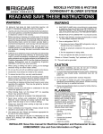
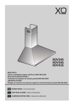
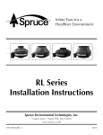
MODELS 2830 & 2836 ECLIPSE
DOWNDRAFT BLOWER SYSTEM
READ AND SAVE THESE INSTRUCTIONS
WARNING
WARNING
TO REDUCE THE RISK OF FIRE, ELECTRIC SHOCK, OR
INJURY TO PERSONS, OBSERVE THE FOLLOWING:
1. SMOTHER FLAMES with a close-fitting lid, cookie sheet,
or metal tray, then turn off the burner. BE CAREFUL TO
PREVENT BURNS. If the flames do not go out immedi
ately, EVACUATE AND CALL THE FIRE DEPARTMENT.
1. Use this unit only in the manner intended by the manufacturer.
If you have questions, contact the manufacturer at the address
or telephone number in the warranty.
2. NEVER PICK UP A FLAMING PAN - You may be burned.
3. DO NOT USE WATER, including wet dishcloths or towels
- a violent steam explosion will result.
2. Before servicing or cleaning unit, switch power off at service
panel and lock the service disconnecting means to prevent
power from being switched on accidentally. When the service
disconnecting means cannot be locked, securely fasten a
prominent warning device, such as a tag, to the service panel.
4. Use an extinguisher ONLY if:
A. You know you have a Class ABC extinguisher, and you
already know how to operate it.
3. Installation work and electrical wiring must be done by a
qualified person(s) in accordance with all applicable codes
and standards, including fire-rated construction codes and
standards.
4. Sufficient air is needed for proper combustion and exhausting
of gases through the flue (chimney) of fuel burning equipment
to prevent backdrafting. Follow the heating equipment
manufacturer’s guideline and safety standards such as those
published by the National Fire Protection Association (NFPA),
and the American Society for Heating, Refrigeration and Air
Conditioning Engineers (ASHRAE), and the local code authorities.
5. When cutting or drilling into wall or ceiling, do not damage
electrical wiring and other hidden utilities.
B. The fire is small and contained in the area where it
started.
C. The fire department is being called.
D. You can fight the fire with your back to an exit.
a
Based on “Kitchen Firesafety Tips” published by NFPA.
CAUTION
1. For general ventilating use only. Do not use to exhaust
hazardous or explosive materials and vapors.
6. Ducted fans must always be vented to the outdoors.
2. To avoid motor bearing damage and noisy and/or unbalanced impellers, keep drywall spray, construction dust, etc.
off power unit.
7. Do not use this unit with an additional speed control device.
3. Clean filters and grease-laden surfaces frequently.
7. To reduce the risk of fire, use only metal ductwork.
4. Do not repair or replace any part of this appliance unless
specifically recommended in this manual. All other servicing
should be done by a qualified technician.
8. Do not install this product with the activating switch directly
behind a burner or element. Minimum distance between the
switch and the edge of the burner should be 4 inches.
9. Loose-fitting or hanging clothing should never be worn when
operating this appliance. They may be ignited by burners/
elements on cooktop.
5. Please read specification label on product for further information and requirements.
10.Children should not be left alone or unattended in the area
where this appliance is in use.
PLANNING
11.When flaming foods, turn the blower OFF. An operating
blower may spread the flames.
This downdraft blower system is
designed to be used to exhaust
airborne contaminants when
cooking with a variety of gas or
electric cooktops. It can be
mounted in island, peninsula, or
conventional wall locations.
12. This unit must be grounded.
TO REDUCE THE RISK OF A RANGE TOP GREASE FIRE:
1. Never leave surface units unattended at high settings.
Boilovers cause smoking and greasy spillovers that may
ignite. Heat oils slowly on low or medium settings.
2. Always turn hood ON when cooking at high heat or when
cooking flaming foods.
3. Clean ventilating fans frequently. Grease should not be
allowed to accumulate on fan or filter.
4. Use proper pan size. Always use cookware appropriate for
the size of the surface element.
TO REDUCE THE RISK OF INJURY TO PERSONS IN THE
EVENT OF A RANGE TOP GREASE FIRE, OBSERVE THE
FOLLOWINGa:
TYPICAL INSTALLATION
CHIMNEYTOP
COUNTER
COOKTOP
TOP
AIR
VENT
This system can be easily installed
following these basic steps:
•
•
•
•
•
Cut out the countertop
opening.
Mount the unit in the
cabinet.
Install exterior blower
Connect the ductwork
and electrical.
Install the cooktop.
3-1/4" x 10"
DUCT CONNECTOR
120 VAC
GROUNDED
OUTLET
INSTALLER: Save this manual for Electrical Inspector and Homeowner to use.
HOMEOWNER: Use and Care Information on Page 4.
PLANNING - (continued)
PLAN THE DUCTWORK
Note: The high level of air flow of this appliance may affect the gas
flame on some types of gas cooktops. This is NORMAL and will
cause no harm, but can be corrected by lowering the speed of the
blower.
SPECIFICATIONS
VOLTS AMPS
120 6.0 MAX.
Hz. DISCHARGE
60 3-1/4 X 10
Install downdraft with an exterior blower that draws 6.0 AMPS or
less.
3-1/4" x 10"
DISCHARGE
1. This downdraft blower system is most efficient when used with
10" round ductwork. Use a combination of elbows and transitions (shown below), closest to the downdraft, in order to get
from 3¼" x 10" to 10" round as soon as possible.
TAKE MEASUREMENTS
2. For best performance: Choose the ducting option which allows
the shortest length of ductwork and a minimum number of
elbows and transitions. Check location of floor joists, wall
studs, electrical wiring or plumbing for possible interference.
1. Refer to the cooktop installation instructions for dimensions of
cooktop, countertop cut-out, and cabinet requirements. The
Model 2830 will fit in most 30" wide cabinets and the Model
2836 will fit in most 36" wide cabinets. However, it is recommended that oversized cabinets be used for easier installation.
3-1/4" X 10"
TO 8" RD.
TRANSITION
8" ROUND
ELBOW
2. Cooktop depth can vary greatly from one to another. This may
cause the fit of these two appliances to be rather tight.
EQUALS 6 FT. OF
STRAIGHT DUCT
EQUALS 2
FT. OF
STRAIGHT DUCT
3-1/4" X 10"
90O ELBOW
8" - 10"
INCREASER
EQUALS 8
FT. OF
STRAIGHT DUCT
3. The system will operate most efficiently when the ductwork
does not exceed 40 feet of equivalent duct. The illustrations,
above, shows equivalent feet of elbows and transitions. The
number of feet of straight duct plus the equivalent feet of
transitions and/or elbows to be used should equal 40 feet or
less.
Pay special attention to the areas of potential interference highlighted above. A countertop with (A) a raised lip and/or (B) a
backsplash may not allow enough flat countertop for a proper
installation. Note that 2" of flat countertop is required behind
cooktop and that 1-3/4" is necessary between the back edge of the
cooktop and the inside of cabinet back.
NOTE: The equivalent feet of various roof and wall caps has
been taken into consideration. Do not include them in this
calculation.
PLAN THE WIRING
1. The downdraft and exterior blower system normally draws 6
AMPS and requires a 120 VAC, 60 Hz circuit.
2
2. The unit has a 2 ft. long power cord with a 3-pronged plug. Plan
to provide a grounded outlet in a location which will allow the
unit’s power cord to reach. (Note: If the Model 2830 is being
installed in a 30" wide cabinet or the Model 2836 is being
installed in a 36" wide cabinet, the outlet cannot be located on
the back wall of cabinet.) Outlet may also be wall-mounted,
with access hole in cabinet.
CUT COUNTERTOP OPENING
INSTALL DUCTWORK
1. Lay out and cut the cooktop cut-out far enough FORWARD so
downdraft will fit behind it.
CAUTION - BEFORE CUTTING HOLE IN CABINET FOR DUCTWORK: Check for interference with floor joists, wall studs, electrical wiring or plumbing.
2. Set cooktop in place and slide it as far forward as possible.
Center and square it with edges of countertop.
OUTLET
ASSEMBLY
COLLAR
TRANSITION
ELBOW
3. Place the plastic template against the back flange of the
cooktop and center it. Trace around template to mark the
downdraft opening.
1. Cut hole in cabinet as well as holes in wall or floor as
necessary.
4. Remove cooktop from countertop.
5. Cut downdraft opening. Be careful not to chip edges of
countertop.
2. Mount the exterior blower and work back towards the cabinet,
attaching all ductwork, elbows and transitions as previously
planned. Tape all ductwork connections to make them secure
and air tight.
MOUNT THE UNIT
3. Connect ductwork (and transition, if required) to downdraft. If
necessary, LOOSEN nuts and screws that hold the blower in
place, and slide outlet assembly left or right to meet ductwork.
Re-tighten screws and nuts.
MOUNTING SCREWS
INSTALL ELECTRICAL WIRING
1. Mount a standard wiring box, with 3-pronged grounded receptacle, inside the kitchen cabinet. Make sure the unit's power
cord can easily reach it.
2. Run appropriate power cable into cabinet and connect it to
electrical box and receptacle.
3. Exterior blower may not exceed 6.0 Amp rating.
4. Run 2-wire plus ground power cable from the remote blower
to wiring box on downdraft. Remove wire box cover and attach
cable using proper certified or recognized connector. Use
recognized wire connectors to connect wires. Make sure wires
cannot come loose from connectors after assembly.
1. Set downdraft into opening. Extend leveling brackets to floor
of cabinet so downdraft sits straight. (Note: Leveling brackets
can be removed and re-attached in other positions. Bottom
flange may have to face inward in tight cabinet installations.)
5. Connect downdraft wiring to power cable from remote blower.
Wire black to black, white to white and green to green or bare
wire.
2. Secure the downdraft to the countertop as follows: Hold the
downdraft against the back of countertop cut-out and tightening the 2 mounting screws (one on each end of unit) on
underside of countertop. Use a wood shim between screw and
underside of granite countertops.
6. Replace wiring box cover.
3. Screw leveling brackets to bottom of cabinet. Tighten screws
holding leveling bracket to unit on each side.
3
3. Remove switch cover from right end of air vent.
WIRING DIAGRAM
4. Loosen the 2 screws holding the switch bracket in place.
Position switch bracket so that activating switch just comes in
contact with underside of switch membrane. Tighten screws.
5. Replace switch cover, gently lower air vent into chimney, and
plug in power cord. Re-connect electrical power and check
operation.
USE AND CARE
Always turn the downdraft blower on before you begin cooking to
establish an air flow in the kitchen. Let the blower run for a few
minutes to clean the air after you turn the cooktop off. This will
keep the whole kitchen cleaner and brighter.
CONTROLS
INSTALL COOKTOP
1. Align the cooktop with the downdraft and fasten cooktop in
place.
Note: Accurate alignment of cooktop and downdraft is necessary
to ensure that there is no interference when air vent is raised and
lowered. There should be a gap of 1/32"-1/16" between the back
of the cooktop and the front of the downdraft cover.
Turn the downdraft blower ON by pressing down on the activating
switch. The air vent will rise.
ADJUSTMENT
KNOB
The downdraft is factory-adjusted for proper operation. However,
shipping and handling may affect the position of the activating
switch.
To adjust position of activating switch:
The blower can be turned ON or OFF and its speed can be
adjusted with the recessed knob on the right side of the air vent.
WARNING: To avoid possible electrical
shock, personal injury or death Disconnect electrical power.
1. If downdraft is plugged into electrical outlet, unplug it.
2. Lift air vent straight up and cock it slightly so it remains in the
UP position.
Turn the downdraft blower OFF by pressing the activating switch
again. The air vent will go down and the blower will shut OFF.
SWITCH
MEMBRANE
Note: For most convenient operation, set the blower to your
favorite speed. The blower will come on to this speed whenever
the activating switch is pressed and the air vent rises.
SCREWS
SWITCH
BRACKET
SWITCH
COVER
4
SERVICING
USE AND CARE - (Continued)
CLEANING
WARNING: Always disconnect electric
power supply before servicing unit.
WARNING: Always disconnect electric
power supply before cleaning unit.
It may be necessary to remove the outlet assembly from the
cabinet in order to service components such as the blower motor
or air vent mechanism.
Use a mild detergent suitable for painted surfaces. DO NOT USE
ABRASIVE CLOTH, STEEL WOOL PADS, OR SCOURING
POWDERS.
Disconnect power to the cooktop and remove it first. Reverse the
steps under “MOUNT THE UNIT” to remove the downdraft from
the cabinet.
Wash the 2 aluminum grease filters in a mild detergent solution or
a dishwasher. Remove them from the air vent by grasping the tab
at the top of each filter.
Service parts are available from your local Broan distributor or
from Broan Service Department, P.O. Box 140, Hartford, WI
53027 Phone: 1-800-637-1453.
Note: The filters are different sizes. Be sure to replace them as
removed, (wider one on the left), with tabs UP.
5
SERVICE PARTS
Models 2830 & 2836
Downdraft Blower Systems
KEY NO. PART NUMBER
1
3
4
5
8
10
11
12
16
17
18
19
**
93400038
99400024
93470012
97011927
99360165
97009972
97011293
97010997
98007642
98007780
98008168
97011325
97011326
98008175
99710032
97011259
97011260
97011322
97011323
97010999
97011443
97010998
97011000
97009786
97009787
99090939
99080295
99110850
99170245
99150471
99150526
99150488
98008186
99260488
98008174
98008173
97011500
98008187
99200202
99160225
99160356
99160361
99260437
99380633
99400060
93260447
98008415
93270493
99160382
99150415
98008183
98008166
99100503
99100504
97011320
**
97011321
22
23
24
25
26
28
29
30
33
45
46
47
49
50
51
52
53
54
55
56
57
58
60
61
62
64
66
67
68
70
71
74
75
76
82
84
DESCRIPTION
QTY.
Bushing, 7/8"
Bushing, Heyco, 1/2"
Roller
Switch Assembly, Up/Down
Knob
Lower Switch Bracket Assembly
Green Ground Wire
Wire Harness
Back-up Plate
Crank
Switch Cover
Chimney Assembly with Slide (Model HV303)
Chimney Assembly with Slide (Model HV363)
Outlet Extension
Spacer
Top Bracket Assembly, Right
Top Bracket Assembly, Left
Top, Stainless (30")
Top, Stainless (36")
Outlet Assembly
Gear Motor Cover
Air Box Assembly (30")
Air Box Assembly (36")
Filter Kit (30") (contains 2 filters)
Filter Kit (36") (contains 2 filters)
End Cap
Gearmotor
Slide Strip
Screw, #8-18 x .375 SLT HX WS HD
Screw, #10-32 x .500 HX WS BDRH
Screw, #8-18 x .250 SA PH TRH
Screw, #8-18 x .500 No. 5 PH Trim
Cover, Air Box Opening
Nut, 10-24
Air Box Cover (30")
Air Box Cover (36")
Gearmotor Bracket Assembly
Leg Support
Screw, 1/4-20 x 1/2 SEMS
Screw, #8-32 x 1/2 PH HD MS
Screw, #10-24 x 3/8 SH WH LOCK
Screw, #10-24 x 3/8 PH FL HD LD
Nut, 10-24 HEX KEPS
U-Bolt, 10-24
Strain Relief
Nut, Hex Flange
Wire Channel Clamp
Wire Tie
Screw, 1/4-20 x 1.250 Hex. Hd.
#8-18 x .250 PH TR HD BPT
Outlet Box Cover
Cover - Gear Motor
Seal - Foam (30")
Seal - Foam (36")
Chimney Assembly, Complete (30") (Includes Key
Nos. 5, 8, 19, 45, 51, 52, & 71)
Chimney Assembly, Complete (36") (Includes Key
Nos. 5, 8, 19, 45, 51, 52, & 71)
2
1
1
1
1
1
1
1
1
1
1
1
1
1
2
1
1
1
1
1
1
1
1
1
1
1
1
3
16
2
6
2
1
4
1
1
1
2
5
4
1
1
6
1
1
1
2
3
2
3
1
1
1
1
* Standard Hardware - May be purchased locally.
** Service Assembly - Contains numerous parts
6
OPTIONAL DOOR KITS
MODEL NO.
DESCRIPTION
273001C
273002C
273023C
273601C
273602C
273623C
30" White
30" Biscuit
30" Black
36" White
36" Biscuit
36" Black
SERVICE PARTS
Models 2830 & 2836
Downdraft Blower Systems
24
51
52
5
26
8 45
71
25
47
1
23
51
51
71
12
67
4
74
30
15
62
19
16 17
10
68
60
64
18
33
49 50
1
49
61
66
76
3
56
57
84
49
46
58
53
64
55
75
28
29
82
70
11
54
22
49
7
50
WARRANTY
BROAN-NUTONE ONE YEAR LIMITED WARRANTY
Broan-NuTone warrants to the original consumer purchaser of its products that such
products will be free from defects in materials or workmanship for a period of one year
from the date of original purchase. THERE ARE NO OTHER WARRANTIES,
EXPRESS OR IMPLIED, INCLUDING, BUT NOT LIMITED TO, IMPLIED WARRANTIES OF MERCHANTABILITY OR FITNESS FOR A PARTICULAR
PURPOSE.
During this one-year period, Broan-NuTone will, at its option, repair or replace,
without charge, any product or part which is found to be defective under normal use
and service.
THIS WARRANTY DOES NOT EXTEND TO FLUORESCENT LAMP STARTERS
AND TUBES. This warranty does not cover (a) normal maintenance and service or
(b) any products or parts which have been subject to misuse, negligence, accident,
improper maintenance or repair (other than by Broan-NuTone), faulty installation or
installation contrary to recommended installation instructions.
The duration of any implied warranty is limited to the one-year period as specified for
the express warranty. Some states do not allow limitation on how long an implied
warranty lasts, so the above limitation may not apply to you.
BROAN-NUTONE’S OBLIGATION TO REPAIR OR REPLACE, AT BROANNUTONE’S OPTION, SHALL BE THE PURCHASER’S SOLE AND EXCLUSIVE
REMEDY UNDER THIS WARRANTY. BROAN-NUTONE SHALL NOT BE LIABLE FOR INCIDENTAL, CONSEQUENTIAL OR SPECIAL DAMAGES ARISING
OUT OF OR IN CONNECTION WITH PRODUCT USE OR PERFORMANCE.
Some states do not allow the exclusion or limitation of incidental or consequential
damages, so the above limitation or exclusion may not apply to you.
This warranty gives you specific legal rights, and you may also have other rights,
which vary from state to state. This warranty supersedes all prior warranties.
To qualify for warranty service, you must (a) notify the appropriate company at the
address or phone number below (b) give the model number and part identification and
(c) describe the nature of any defect in the product or part. At the time of requesting
warranty service, you must present evidence of the original purchase date.
In the U.S. contact:
Broan-NuTone LLC, 926 West State Street, Hartford, WI 53027 (1-800-637-1453)
In the U.S. contact:
NuTone, Inc., 4820 Red Bank Road, Cincinnati, OH 45227 (1-800-543-8687)
99042138L