1
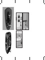
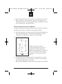
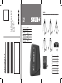
Accessories / Accessories / Accesorios / Tillbehör / Tilbehør / Lisävarusteet
X2
Gebrauchsanweisung
D
5 . . . . 14
Operating instructions
GB
15 . . . . 24
Mode d’emploi
F
25 . . . . 34
Instruzioni d’uso
I
35 . . . . 44
Instrucciones de uso
E
45 . . . . 54
Gebruiksaanwijzing
NL
55 . . . . 64
A
B
C
D
E
F
A . . . . . . . . . . . . . . . . . UST
B . . . . . . . . . . . . . . . . . TST
Kaufdatum / Stempel / Unterschrift des Händler
C . . . . . . . . . . . . . . . . . KST
D . . . . . . . . . . . . . . . . . BST
G
E . . . . . . . . . . . . . . . . . BSTX
F . . . . . . . . . . . . . . . . . LB
✂
Telefon / Telephone
Date of purchase / Stamp / Signature (dealer)
Unteres Tobel 25
A-6840 Götzis
Austria
Sola-Messwerkzeuge GmbH
Adresse / address
Firma / Company / Name
Seriennummer / Serial no.
Guarantee certificate X2
Gewährleistungskarte X2
Zubehör
G . . . . . . . . . . . . . . . . . ZLM
1
2
3
4
5
Sola Inhalt X2.qxd:inlet_X2
08.04.2008
13:57 Uhr
Seite 5
D
1. Vorwort
Wir gratulieren Ihnen zum Kauf Ihres neuen Messgerätes. Sie haben ein
Präzisionsmessgerät mit genau justiertem Laser erworben! Das Vereinfachen
von Messungen, das Verbessern der Messergebnisse und Zeitersparnis sind
der Antrieb für die Entwicklung unserer Produkte.
Lesen Sie bitte diese Bedienungsanleitung aufmerksam durch, bevor Sie das
Gerät verwenden. Machen Sie Warnschilder am Messwerkzeug niemals
unkenntlich. Bewahren Sie diese Anweisungen gut auf.
2. Inhalt
3. Beschreibung . . . . . . . . . . . . . . . . . . . . . . . . . . . . . . . . . . . . . . . . . . . . . 6
4. Sicherheitshinweise . . . . . . . . . . . . . . . . . . . . . . . . . . . . . . . . . . . . . . . . 6
5. Technische Daten . . . . . . . . . . . . . . . . . . . . . . . . . . . . . . . . . . . . . . . . . . 8
6. Bedienung . . . . . . . . . . . . . . . . . . . . . . . . . . . . . . . . . . . . . . . . . . . . . . . . 9
7. Genauigkeit des Instruments überprüfen . . . . . . . . . . . . . . . . . . . . . . . 10
8. Gewährleistung . . . . . . . . . . . . . . . . . . . . . . . . . . . . . . . . . . . . . . . . . . . 13
9. Reinigung . . . . . . . . . . . . . . . . . . . . . . . . . . . . . . . . . . . . . . . . . . . . . . . 13
10. Entsorgung . . . . . . . . . . . . . . . . . . . . . . . . . . . . . . . . . . . . . . . . . . . . . . 14
5
Sola Inhalt X2.qxd:inlet_X2
08.04.2008
13:57 Uhr
Seite 6
D
3. Beschreibung
Die Nummerierung der Geräteelemente bezieht sich auf die Darstellung des
Gerätes auf der Grafikseite.
� Ein-/Austaste mit Transportsicherung
� Taste „Mode“ (Linienfunktionen)
� Ausgang Laserstrahlen
� Stativgewinde (5/8“)
� Batteriedeckel
4. Sicherheitshinweise
Bitte lesen Sie vor Inbetriebnahme des Gerätes die Bedienungsanleitung sowie die Sicherheitshinweise vollständig und halten Sie sich
strikt an diese Angaben.
2M
Laserstrahlung / Laserklasse 2M / (< 5 mW; 635 nm)
gemäß DIN EN 60825-1: 2003-10
Nicht in den Laserstrahl blicken! Ein direkter Blick in den
Laserstrahl, insbesondere mit optischen sammelnden Instrumenten
wie Fernglas usw. – kann das Auge schädigen.
Das Messinstrument vor Nässe schützen!
Messinstrument nicht fallen lassen!
Der Betreiber informiert den Benutzer über die Gebrauchsgefahren der Ausrüstung und schützende Gegenmaßnahmen. Das Gerät darf erst dann in
Betrieb genommen werden, wenn der Benutzer instruiert ist.
6
Sola Inhalt X2.qxd:inlet_X2
08.04.2008
13:57 Uhr
D
Sachwidrige Verwendung
• Verwendung des Produktes ohne Instruktion.
• Verwendung außerhalb der Einsatzgrenzen.
• Unwirksammachen von Sicherheitseinrichtungen und entfernen
von Hinweis- und Warnschildern.
• Öffnen des Produktes mit Werkzeugen (Schraubenzieher etc.),
sofern nicht ausdrücklich für bestimmte Fälle erlaubt.
• Durchführung von Umbauten oder Veränderungen am Produkt.
• Inbetriebnahme nach Entwendung.
• Verwendung von Zubehör anderer Hersteller, welches vom Hersteller
nicht ausdrücklich genehmigt ist.
• Bewusstes oder leichtsinniges Hantieren beim Messen in der Nähe
laufender Maschinen, offener Maschinenelemente oder Anlagen.
• Direktes Zielen auf Personen; auch bei Dunkelheit.
• Gerät nicht extremen Temperaturen und Temperaturschwankungen
aussetzen (z.B. nicht im Auto liegen lassen).
• Wird das Gerät längere Zeit nicht benutzt, müssen die Batterien
herausgenommen werden (Gefahr von Selbstentladung und Korrosion).
• Verwenden Sie die Laser-Sichtbrille nicht als Schutzbrille.
• Verwenden Sie die Laser-Sichtbrille nicht als Sonnenbrille
oder im Straßenverkehr.
7
Seite 7
Sola Inhalt X2.qxd:inlet_X2
08.04.2008
13:57 Uhr
Seite 8
D
5. Technische Daten
Laserklasse:
Lasertyp:
Max. Messtoleranz:
Selbstnivellierend:
Nivellierzeit:
Linienlänge:
Einsatzbereich:
Laserdioden:
Kreuzwinkel:
Gewicht:
Transportschutztasche:
Stromversorgung:
Betriebsdauer:
Arbeitstemperatur:
Lagertemperatur:
2M, gemäß DIN EN 60825-1: 2003-10
635 nm / <5 mW
1,0 mm/m
± 5°
4 sec.
6 m (horizontal), 4 m (vertikal)
bei 3 m Abstand
r = 15 m, je nach Lichtverhältnissen
am Arbeitsplatz
2 x 635 nm Halbleiterdioden
Laserklasse 2M, DIN EN 60825-1: 2003-10
90°
Instrument: 400 g
200 g
2x 1,5V AA-Batterien
ca. 12 h (Dauerbetrieb bei 20°)
0° C bis +40°C
-20° C bis +60°C
Änderungen in den Angaben sind vorbehalten.
8
Sola Inhalt X2.qxd:inlet_X2
08.04.2008
13:57 Uhr
Seite 9
D
6. Bedienung
Die Ein- / Aus-Taste 1 in Richtung „ON“ drücken. Das Gerät startet immer im
Kreuzlinienbetrieb mit Nivellierüberwachung. Das Gerät sendet sofort nach
dem Einschalten einen Laserstrahl aus der Austrittsöffnung 3.
MESSFUNKTIONEN
Betrieb mit Nivellierüberwachung
Bei Nivellierüberwachung gleicht das Gerät Unebenheiten innerhalb des
Selbstnivellierbereiches von ca. 5° automatisch aus. Die Nivellierung ist abgeschlossen, sobald sich die Laserlinie nicht mehr bewegt. Ist die automatische Nivellierung nicht möglich, z.B. weil die Standfläche des Gerätes mehr
als 5° von der Waagerechten abweicht, ertönt ein Warnsignal und der Laser
schaltet sich ab. In diesem Fall das Gerät waagerecht aufstellen und die
Selbstnivellierung abwarten.
Kreuzlinienbetrieb (siehe Bild )
Das Gerät auf eine waagerechte, feste Unterlage stellen oder auf einem Stativ
befestigen und einschalten. Der Laser ist im Kreuzlinienbetrieb mit Nivellierüberwachung und erzeugt je eine waagrechte und eine senkrechte Linie.
Horizontalbetrieb (siehe Bild )
Die Taste „mode �“ einmal betätigen. Der Laser ist im Horizontalbetrieb mit
Nivellierüberwachung und erzeugt nur eine waagrechte Linie.
Vertikalbetrieb (siehe Bild )
Die Taste „mode �“ erneut oder direkt nach dem Einschalten zweimal betätigen. Der Laser ist im Vertikalbetrieb mit Nivellierüberwachung und erzeugt
nur eine senkrechte Linie.
9
Sola Inhalt X2.qxd:inlet_X2
08.04.2008
13:57 Uhr
Seite 10
D
Kreuzlinienbetrieb ohne Nivellierüberwachung (siehe Bild )
Die Taste Messmodus „mode �“ erneut oder direkt nach dem Einschalten
dreimal betätigen. Die Nivellierüberwachung ist jetzt ausgeschaltet. In diesem Modus kann das Gerät frei in der Hand gehalten oder auf einem Stativ
geneigt werden. Der Laser erzeugt zwei gekreuzte Linien, die frei ausgerichtet
werden können und deshalb nicht mehr zwingend senkrecht zueinander
verlaufen. Erneutes Betätigen der Taste „mode �“ bringt das Gerät wieder in
den Betrieb mit Nivellierüberwachung.
Arbeiten mit Stativ (siehe Bild )
Ein Stativ bietet eine stabile, höheneinstellbare Messunterlage. Das Gerät mit
dem „Gewinde �“ an der Gehäuseunterseite auf ein handelsübliches Stativ
mit 5/8"-Gewinde aufschrauben.
7. Genauigkeit des Instruments überprüfen
Überprüfen Sie regelmäßig die Genauigkeit des Instruments.
Führen Sie dazu die folgenden Tests aus:
Genauigkeit des Nivellierstrahls (zwischen Instrument und Zielpunkt)
�
Geben Sie das Gerät auf das
Stativ und stellen Sie das
Gerät möglichst nahe an
eine Wand (A), welche
ca. 5 m von einer gegenüberliegenden Wand ( B)
entfernt ist (Fig. 2).
10
Sola Inhalt X2.qxd:inlet_X2
08.04.2008
13:57 Uhr
Seite 11
D
� Drücken Sie beide Knöpfe, um sowohl die horizontale als auch die vertikale
Linie zuzuschalten und projizieren Sie ein Kreuz auf die Wand A. Markieren
Sie Punkt „a1“, wo sich die beiden Linien schneiden. Drehen Sie das Gerät
um 180° und markieren Sie Punkt „b“ am Schnittpunkt der beiden Linien
auf Wand B (Fig. 2).
�
Stellen Sie das Gerät im
Stativ möglichst nahe an die
gegenüberliegende Wand B
und stellen Sie das Gerät
auf Punkt „b“ ein. Drehen
Sie das Gerät um 180° und
markieren Sie Punkt „a2“.
(Fig. 3).
� Messen Sie die Distanz zwischen „a1“ und „a2“ . Ist die Gesamtabweichung
< 5 mm (2x 5m Messung), dann ist die Messgenauigkeit innerhalb der
Toleranz. Ist sie darüber, kontaktieren Sie bitte den Händler, bei dem Sie das
Gerät gekauft haben.
Waagrechter Nivellierstrahl (zwischen zwei Endpunkten)
� Setzen Sie das Instrument auf das Stativ und stellen Sie es etwa 5 m
entfernt von einer Wand auf.
�
Drücken Sie die beiden Tasten für die
senkrechte und waagrechte Ebene,
um ein Laserkreuz auf die Wand zu
projizieren. Markieren Sie am Schnittpunkt der Strahlen den Punkt "A" und
markieren Sie 2,5 m von Punkt "A"
entfernt auf dem waagrechten Strahl
den Punkt "M1" (Fig. 4).
11
Sola Inhalt X2.qxd:inlet_X2
08.04.2008
13:57 Uhr
Seite 12
D
� Drehen Sie das Instrument, bis sich der senkrechte Strahl um 5 m verschoben hat, zu Punkt "B". Messen Sie den Abstand "E". Wenn der Abstand "E"
maximal 2,5 mm beträgt, ist die Genauigkeit innerhalb der Toleranz.
Bei größeren Abweichungen wenden Sie sich an einen Händler (Fig. 4).
Senkrechter Lotstrahl (zwischen zwei Endpunkten)
Um optimale Ergebnisse zu erzielen, montieren Sie das Instrument auf einer
Nivellierplattform, die zwischen Boden und Decke befestigt ist (z.B. Klemmsäule).
� Setzen Sie das Instrument in die Halterung ein, montieren Sie es an der
Nivellierplattform und stellen Sie das Instrument etwa 5 m von einer Wand
entfernt auf. Senken Sie das Instrument so weit wie möglich zum Fußboden
hinab.
�
Drücken Sie die beiden Tasten für die
senkrechte und waagrechte Ebene, um ein
Laserkreuz auf die Wand zu projizieren.
Markieren Sie am Schnittpunkt der Strahlen
den Punkt "A" und markieren Sie 1,2 m von
Punkt "A" entfernt auf der Lotlinie den
Punkt "M1" (Fig. 5).
� Heben Sie das Instrument bis sich der waagrechte Strahl um 2,5 m verschoben hat, zu Punkt "B". Messen Sie den Abstand "E". Wenn der Abstand "E"
maximal 1,2 mm beträgt, liegt die Genauigkeit innerhalb der Toleranz.
Bei größeren Abweichungen wenden Sie sich an einen Händler.
12
Sola Inhalt X2.qxd:inlet_X2
08.04.2008
13:57 Uhr
Seite 13
D
8. Gewährleistung
Der Hersteller garantiert dem aus der Gewährleistungskarte ersichtlichen
ursprünglichen Käufer (Ersterwerber) die Fehlerfreiheit des Produktes für die
Dauer von zwei Jahren ab Übergabe.
Die Gewährleistung beschränkt sich auf Reparaturen und / oder Ersatz nach
Wahl des Herstellers. Mängel aufgrund unsachgemäßer Behandlung durch
den Käufer oder durch Dritte, natürliche Verschleißerscheinungen und optische Mängel, die die Verwendung des Gerätes nicht beeinflussen, werden von
dieser Gewährleistung nicht erfaßt.
Ansprüche aus dieser Gewährleistung können nur geltend gemacht werden,
wenn zusammen mit dem Gerät die vom Verkäufer ausgefüllte und mit Datum
und Firmenstempel versehene Gewährleistungskarte eingereicht wird.
Bei Gewährleistungsanspruch vergütet der Hersteller die Transportkosten.
Die Dauer der Gewährleistung wird durch Reparaturen oder Ersatzteilarbeiten,
die im Rahmen der Garantie erfolgen, nicht verlängert.
9. Reinigung
Gerät stets sauber und trocken halten. Verschmutzungen mit feuchtem, weichem Tuch abwischen. Keine scharfen Reinigungs- oder Lösemittel verwenden. Den „Laserausgang �“ regelmäßig mit Hilfe von Wattestäbchen reinigen und Fusseln entfernen.
Vor jedem Gebrauch das Gerät überprüfen. Bei sichtbaren Beschädigungen
oder losen Teilen im Inneren des Gerätes ist eine sichere Funktion nicht mehr
gewährleistet.
13
Sola Inhalt X2.qxd:inlet_X2
08.04.2008
13:57 Uhr
Seite 14
D
10. Entsorgung
Messwerkzeuge, Zubehör und Verpackungen sollen einer umweltgerechten
Wiederverwertung zugeführt werden.
Nur für EU-Länder
Werfen Sie Messwerkzeuge nicht in den Hausmüll! Gemäß der Europäischen
Richtlinie 2002/96/EG über Elektro- und Elektronik-Altgeräte und ihrer Umsetzung in nationales Recht, müssen nicht mehr gebrauchsfähige Messwerkzeuge getrennt gesammelt und einer umweltgerechten Wiederverwertung
zugeführt werden.
14
Sola Inhalt X2.qxd:inlet_X2
08.04.2008
13:57 Uhr
Seite 15
GB
1. Introduction
Congratulations on buying your new measurement instrument. You are now
the owner of a precision measuring device with a finely adjusted laser. In
developing our products, our goals are to simplify the measuring process,
improve results and save time.
Please read this operating manual attentively before you use the device. Never
obliterate, or remove, the warning signs on the measuring tool. Keep these
instructions somewhere safe.
2. Contents
3. Description . . . . . . . . . . . . . . . . . . . . . . . . . . . . . . . . . . . . . . . . . . . . . . 16
4. Safety instructions . . . . . . . . . . . . . . . . . . . . . . . . . . . . . . . . . . . . . . . . 16
5. Technical data . . . . . . . . . . . . . . . . . . . . . . . . . . . . . . . . . . . . . . . . . . . 18
6. Operation . . . . . . . . . . . . . . . . . . . . . . . . . . . . . . . . . . . . . . . . . . . . . . . 19
7. Checking the accuracy of the instrument . . . . . . . . . . . . . . . . . . . . . . . 20
8. Warranty . . . . . . . . . . . . . . . . . . . . . . . . . . . . . . . . . . . . . . . . . . . . . . . . 23
9. Cleaning . . . . . . . . . . . . . . . . . . . . . . . . . . . . . . . . . . . . . . . . . . . . . . . . 23
10. Disposal . . . . . . . . . . . . . . . . . . . . . . . . . . . . . . . . . . . . . . . . . . . . . . . . 24
15
Sola Inhalt X2.qxd:inlet_X2
08.04.2008
13:57 Uhr
Seite 16
GB
3. Description
The numbering of the device elements refers to the display of the device on
the graphics page.
� On/Off switch with transport lock
� “Mode” button (line functions)
� Laser beam output
� Tripod thread (5/8“)
� Battery cover
4. Safety instructions
Before using the device, please read the operating manual and
safety instructions in full, and apply them carefully in practice.
2M
Laser radiation/laser class 2M / (< 5 mW; 635 nm)
according to DIN EN 60825-1: 2003-10
Do not look into the laser beam. Looking directly into the laser
beam – especially with optical light collecting instruments such as
binoculars, etc. – can damage the eyes.
Do protect the measuring device from moisture.
Do not drop the measuring instrument.
The owner must inform the user as to the operational hazards of the equipment and any protective measures required. The device may only be used after
the user has read and understood the operating and safety instructions.
16
Sola Inhalt X2.qxd:inlet_X2
08.04.2008
13:57 Uhr
Seite 17
GB
Improper use
• Using the product without having received instructions.
• Using the product for purposes other than those for which it is intended.
• Disabling safety equipment and removing instruction and warning signs.
• Opening any part of the device, except for battery compartment/s.
• Modifying or making alterations to the product.
• Using accessories from other manufacturers which have not been expressly
approved by the manufacturer.
• Conscious or negligent handling of the device when measuring in the vicinity
of machines in operation or open machine parts or plants.
• Aiming the device at other persons, even in the dark.
• Exposing the device to extreme temperatures and temperature fluctuations
(e.g. do not leave it in the car).
• It is recommended that batteries be removed during extended periods of
product non use. (risk of self-discharge and corrosion).
• Do not use the laser viewing glasses as protective glasses.
• Do not use the laser viewing glasses as sun glasses or in street traffic.
17
Sola Inhalt X2.qxd:inlet_X2
08.04.2008
13:57 Uhr
Seite 18
GB
5. Technical data
Laser class:
Laser type:
Max. measuring tolerance:
Auto-levelling range:
Levelling time:
Line length:
Operating range:
Laser diodes:
Crossing angle:
Weight:
Transport protection bag:
Power supply:
Operating time:
Operating temperature:
Storage temperature:
2M, according to DIN EN 60825-1: 2003-10
635 nm / <5 mW
1,0 mm/m
±5°
4 sec.
6 m (horizontal), 4 m (vertical)
at a distance of 3 m
(approx) r = 15 m, depending on the light
conditions at the workplace
2 x 635 nm semiconductor diodes
laser class 2M, DIN EN 60825-1: 2003-10
90°
Instrument: 400 g
200 g
2x 1.5 V AA batteries
approx. 12 hours (continuous operation at 20°)
0° C to +40° C
-20° C to +60° C
Modifications reserved.
18
Sola Inhalt X2.qxd:inlet_X2
08.04.2008
13:57 Uhr
Seite 19
GB
6. Operation
Press the On/Off button 1 ON. The device always starts in cross-line mode
with levelling monitoring. After switching the device on, it immediately emits
a laser beam from outlet 3.
MEASUREMENT FUNCTIONS
Operation with levelling monitoring
With the levelling monitoring option, the device automatically compensates
uneveness within the self-levelling range of approx. 5°. The levelling process
is completed as soon as the laser line stops moving. If automatic levelling is
not possible, e.g. because the device’s base deviates from the horizontal
plane by more 5°, a warning signal is emitted and the laser shuts down.
In this case, set up the device in a horizontal position and wait for the
self-levelling operation.
Cross-line mode (see illustration)
Place the device on a firm horizontal surface or fasten it to a tripod and switch
it on. The laser is in cross-line mode with levelling monitoring and it
generates a horizontal line and a vertical line.
Horizontal mode (see illustration)
Press the mode � button once. The laser is in horizontal mode with levelling
monitoring and it only generates a horizontal line.
Vertical mode (see illustration)
Press the mode � button again or press it twice after switching on the
device. The laser is in vertical mode with levelling monitoring and it only
generates a vertical line.
19
Sola Inhalt X2.qxd:inlet_X2
08.04.2008
13:57 Uhr
Seite 20
GB
Cross-line mode without levelling monitoring (see illustration)
Press the mode � measurement mode button again or press it three times
after switching on the device. The levelling monitoring option is now switched
off. In this mode, you can hold the device in your hand or it can be inclined on
a tripod. The laser generates two crossed lines that can be aligned freely and
that therefore do not necessarily need to be at vertical positions.
Press the mode � measurement mode button again to switch the device
back to operation with levelling monitoring.
Working with a tripod (see illustration)
A tripod provides a firm measurement base that can be adjusted in height.
Screw the device with thread � under the housing on to a commercial tripod
with 5/8” thread.
7. Checking the accuracy of the instrument
Check the accuracy of the instrument regularly.
To do this, perform the following tests:
Accuracy of the levelling beam (between instrument and target point)
�
Insert the device in the wall
holder and place the device
on the tripod as near as
possible to a wall (A) that is
approx. 5 m from the wall on
the opposite side (B) (fig. 2).
20
Sola Inhalt X2.qxd:inlet_X2
08.04.2008
13:57 Uhr
Seite 21
GB
� Press both buttons to activate the horizontal line and the vertical line and
project a cross on wall A. Mark point a1 where the two lines cross. Turn the
device through 180° and mark point b at the intersection point of both lines
on wall B. (fig. 2).
�
Place the device on the tripod as close as possible to
the opposite wall B and set
the device to point b. Turn
the device through 180° and
mark the point a2 (fig. 3).
� Measure the distance between a1 and a2. If the total deviation is below
10 mm (2x 5 m measurement), then the measuring accuracy is within the
tolerance. If the total deviation is greater, please contact the dealer who
sold you the device.
Horizontal levelling beam (between two end points)
� Insert the instrument in the holder and set it up at a distance of approx. 5 m
from a wall.
�
Press the two buttons for the vertical
and horizontal planes to project a
laser cross on the wall. Mark the point
A at the intersection point of the
beams and mark point M1 on the horizontal beam, 2.5 m from point A (fig.
4).
21
Sola Inhalt X2.qxd:inlet_X2
08.04.2008
13:57 Uhr
Seite 22
GB
� Turn the device towards point B until the vertical beam has been displaced
by 5 m. Measure the distance E. If the distance E does not exceed 5 mm,
the accuracy is within the tolerance. In the event of significant deviations,
consult an authorised service provider (fig. 4)..
Verticality beam (between two end points)
To achieve optimum results, mount the instrument on a levelling platform that is
fastened between the floor and the ceiling (e.g. clamp column).
� Insert the instrument in the holder and fasten it to the levelling platform.
Then set up the instrument at a distance of roughly 5 m from a wall. Lower
the device as near as possible to the floor.
�
Press both buttons for the vertical and
horizontal planes to project a laser beam
on the wall. Mark the point A at the intersection point of the beams and mark point
M1 on the plumb line, 1.2 m from point
A (fig. 5).
� Raise the instrument towards point B until the horizontal beam has been
displaced by 2.5 m. Measure the distance E. If the distance E does not
exceed 2.5 mm, the accuracy is within the tolerance. In the event of significant deviations, consult an authorised service provider.
22
Sola Inhalt X2.qxd:inlet_X2
08.04.2008
13:57 Uhr
Seite 23
GB
8. Guarantee
The manufacturer guarantees the original buyer, as named on the guarantee
card, that the product shall remain free of manufacturing defects for a period
of two years after purchase.
This guarantee is limited to repair and / or replacement, according to the
manufacturer’s choice. This guarantee does not cover defects arising from
improper use of the device by the buyer or third parties, the natural effects of
ageing, or optical defects not affecting the operation of the device.
Claims under this guarantee are valid only when the device is returned
together with the original, fully completed guarantee card, date stamped by
the original seller.
In the case of a claim under the guarantee, the manufacturer will refund the
reasonable cost of return delivery. The guarantee period is not subject to
further extension (beyond the two years from original purchase date),
following repair or the fitting or replacement parts carried out within the
scope of the guarantee.
This guarantee does not affect your statutory rights.
9. Cleaning
Always keep the device clean and dry. Wipe off any dirt with a soft damp cloth.
Do not use any caustic cleaning agent or solvent. Use cotton swabs to clean
laser output � regularly and remove any lint.
Check the device each time before using it. If there is any visible damage or
if there are loose parts inside the device, safe operation is no longer ensured.
23
Sola Inhalt X2.qxd:inlet_X2
08.04.2008
13:57 Uhr
Seite 24
GB
10. Disposal
Measuring tools, accessories and packaging should be disposed of in an
environmentally sound manner, i.e. recycled.
Only for countries of the EU
Do not dispose of the laser device along, with your household waste!
According to the European Directive 2002/96/EC all unwanted electrical and
electronic devices must be collected separately for specialist disposal.
24
Sola Inhalt X2.qxd:inlet_X2
08.04.2008
13:57 Uhr
Seite 25
F
1. Préambule
Nous vous félicitons pour l’achat de votre nouvel appareil de mesure. Vous
venez d’acquérir un appareil de mesure de précision avec un laser exactement
ajusté ! La simplification des mesures, l’amélioration des résultats de
mesure et le gain de temps sont le moteur du développement de nos produits.
Veuillez lire attentivement ce mode d’emploi avant d’utiliser l’appareil. Veillez
à ce que les panneaux d’avertissement restent toujours lisibles. Conservez
ces instructions.
2. Sommaire
3. Description . . . . . . . . . . . . . . . . . . . . . . . . . . . . . . . . . . . . . . . . . . . . . . 26
4. Consignes de sécurité . . . . . . . . . . . . . . . . . . . . . . . . . . . . . . . . . . . . . . 26
5. Caractéristiques techniques . . . . . . . . . . . . . . . . . . . . . . . . . . . . . . . . . 28
6. Utilisation . . . . . . . . . . . . . . . . . . . . . . . . . . . . . . . . . . . . . . . . . . . . . . . 29
7. Contrôle de la précision de l’appareil . . . . . . . . . . . . . . . . . . . . . . . . . . 30
8. Garantie . . . . . . . . . . . . . . . . . . . . . . . . . . . . . . . . . . . . . . . . . . . . . . . . 33
9. Nettoyage . . . . . . . . . . . . . . . . . . . . . . . . . . . . . . . . . . . . . . . . . . . . . . . 33
10. Elimination . . . . . . . . . . . . . . . . . . . . . . . . . . . . . . . . . . . . . . . . . . . . . . 34
25
Sola Inhalt X2.qxd:inlet_X2
08.04.2008
13:57 Uhr
Seite 26
F
3. Description
La numérotation des éléments de l’appareil se rapporte à la représentation de
ce dernier sur la page des graphiques.
� Touche Marche/arrêt avec protection transport
� Touche « Mode » (fonctions linéaires)
� Sortie faisceaux laser
� Filetage à pied (5/8“)
� Couvercle du compartiment des piles
4. Consignes de sécurité
Avant la mise en service de l’appareil, veuillez lire intégralement le
mode d’emploi ainsi que les consignes de sécurité et vous en tenir
strictement à ces instructions.
2M
Faisceau laser/ classe laser 2M / (< 5 mW; 635 nm)
selon DIN EN 60825-1: 2003-10
Ne regardez pas dans le faisceau laser ! Le fait de regarder directement dans le faisceau laser – surtout avec des instruments ptiques
qui focalisent tels que jumelles etc. – peut endommager l’œil.
Protégez l’instrument de mesure de l’humidité !
Ne laissez pas tomber l’instrument de mesure !
L’exploitant informe l’utilisateur des dangers liés à l’utilisation de
l’équipement et des mesures de protection correspondantes à prendre.
L’appareil ne doit être mis en service que lorsque l’utilisateur a pris connaissance de ces instructions.
26
Sola Inhalt X2.qxd:inlet_X2
08.04.2008
13:57 Uhr
Seite 27
F
Utilisation contre-indiquée
• Utilisation du produit sans instructions.
• Utilisation hors des limites du domaine d’application.
• Neutralisation des dispositifs de sécurité et retrait des panneaux
d’avertissement et de mise en garde.
• Ouverture du produit à l’aide d’outils (tournevis etc.), qui ne sont pas
explicitement admis dans certains cas.
• Réalisation de transformations ou modifications du produit.
• Mise en service du produit après l’avoir dérobé à son propriétaire.
• Utilisation d’accessoires d’autres fabricants n’ayant pas été expressément
autorisés par le fabricant.
• Manipulation consciente ou imprudente lors de mesures à proximité de
machines en marche, d’installations ou d’éléments de machines ouverts.
• Orientation de l’appareil vers des personnes, même dans l’obscurité.
• Exposition de l’appareil à des températures extrêmes et à des variations de
température (ne le laissez pas dans une voiture par exemple).
• En cas de non utilisation prolongée, il est nécessaire de retirer les piles
(risque de corrosion et de déchargement).
• Ne pas utiliser les lunettes de vision du faisceau laser en tant que lunettes
de protection
• Ne pas utiliser les lunettes de vision du faisceau laser en tant que lunettes .
de soleil ou en circulation routière.
27
Sola Inhalt X2.qxd:inlet_X2
08.04.2008
13:57 Uhr
Seite 28
F
5. Caractéristiques techniques
Classe laser :
Type de laser :
Tolérance de musure max. :
Autonivellement :
Type durée de mise à niveau :
Longueur des lignes :
Plage d’utilisation :
Diodes laser :
Angle croisé :
Poids :
Sacoche de transport :
Alimentation :
Durée d’utilisation :
Température de travail :
Température de stockage :
2M, selon DIN EN 60825-1: 2003-10
635 nm / <5 mW
1,0 mm/m
±5°
4 sec.
6 m (horizontales), 4 m (verticales)
pour un écart de 3 m
r = 15 m, en fonction des
conditions de luminosité
sur le poste de travail
2 x 635 nm diodes à semi-conducteurs
classe laser 2M, DIN EN 60825-1: 2003-10
90°
instrument : 400 g
200 g
2x piles AA 1,5 V
env. 12 h (fonctionnement continu à 20°)
de 0° C à +40° C
de -20° C à +60° C
Sous réserve de modifications.
28
Sola Inhalt X2.qxd:inlet_X2
08.04.2008
13:57 Uhr
Seite 29
F
6. Utilisation
Réglez la touche Marche/arrêt 1 sur « ON ». L’appareil démarre toujours en
mode Lignes croisées avec contrôle de la mise à niveau. Dès son activation,
l’appareil émet un faisceau laser par l’ouverture de sortie 3.
FONCTIONS DE MESURE
Fonctionnement avec contrôle de la mise à niveau
Dans le contrôle de la mise à niveau, l’appareil compense automatiquement
les défauts de planéité dans la zone de mise à niveau automatique de 5° env.
La mise à niveau est terminée lorsque la ligne laser est stabilisée. Si la mise
à niveau automatique n’est pas possible, par exemple parce que la surface
de pose de l’appareil s’écarte de plus de 5° de l’horizontale, un signal
d’avertissement retentit et le laser s’arrête. Dans ce cas, placez l’appareil à
l’horizontale et attendez que la mise à niveau automatique soit réalisée.
Mode Lignes croisées (voir fig.)
Placez l’appareil sur un support stable et horizontal ou fixez-le sur un pied
avant de le mettre en service. Le laser fonctionne en mode Lignes croisées
avec contrôle de la mise à niveau et produit respectivement une ligne horizontale et une ligne verticale.
Mode horizontal (voir fig.)
Actionnez une fois la touche « mode � ». Le laser fonctionne en mode horizontal
avec contrôle de la mise à niveau et produit uniquement une ligne horizontale.
Mode vertical (voir fig.)
Actionnez à nouveau la touche « mode � » ou actionnez deux fois cette touche directement après l’activation. Le laser fonctionne en mode vertical avec
contrôle de la mise à niveau et produit uniquement une ligne verticale.
29
Sola Inhalt X2.qxd:inlet_X2
08.04.2008
13:57 Uhr
Seite 30
F
Mode lignes croisées sans contrôle de la mise à niveau (voir fig.)
Actionnez à nouveau la touche du mode de mesure « mode � » ou actionnez
trois fois cette touche directement après l’activation. Le contrôle de la mise à
niveau est maintenant désactivé. Dans ce mode, l’appareil peut être tenu
librement à la main ou être incliné sur un pied. Le laser génère deux lignes
croisées pouvant être orientées librement et qui ne sont donc plus obligatoirement verticales l’une par rapport à l’autre. Si vous actionnez à nouveau la
touche « mode � », l’appareil revient au mode de fonctionnement avec contrôle de la mise à niveau.
Utilisation d’un pied (voir fig.)
Un pied constitue une base de mesure stable et réglable en hauteur. Vissez le
filet � de la partie inférieure du boîtier sur un pied usuel ayant un filet 5/8”.
7. Contrôle de la précision de l’appareil
Contrôlez régulièrement la précision de l’appareil.
Pour cela, effectuez les tests suivants :
Précision du faisceau de niveau (entre l’instrument et la cible)
�
Placez l’appareil dans la
fixation murale et montez-le
sur le pied, si possible à
proximité d’un mur (A) se
trouvant à une distance
d’environ 5 m d’un autre
mur lui faisant face (B)
(Fig. 2).
30
Sola Inhalt X2.qxd:inlet_X2
08.04.2008
13:57 Uhr
Seite 31
F
� Appuyez sur les deux boutons pour générer la ligne horizontale ainsi que la
ligne verticale et projetez une croix sur le mur A. Marquez « a1 » le point
d’intersection des deux lignes. Tournez l’appareil de 180° et marquez le
nouveau point d’intersection « b » sur le mur B (figure 2).
�
Placez l’appareil sur le pied,
aussi près que possible du
mur opposé et réglez
l’appareil sur le point « b ».
Faites pivoter l’appareil de
180° et marquez le point «
a2 ».
(figure 3).
� Mesurez la distance entre les points « a1 » et « a2 ». Si l’écart total est
< 10 mm (mesure 2x 5 m), la précision de mesure est comprise dans la tolérance. Si l’écart est supérieur à cette valeur, contactez votre fournisseur.
Faisceau de mise à niveau horizontal (entre deux points d’extrémité)
� Placez l’instrument dans le support et installez-le à env. 5 m d’un mur.
�
Appuyez sur les deux touches pour le
niveau vertical et le niveau horizontal
afin de projeter une croix sur le mur.
Marquez le point « A » à l’intersection
des faisceaux et le point « M1 » à
2,5 m du point « A » sur le faisceau
horizontal (fig. 4).
31
Sola Inhalt X2.qxd:inlet_X2
08.04.2008
13:57 Uhr
Seite 32
F
� Tournez l’instrument jusqu’à ce que le faisceau vertical se soit déplacé de
5 m environ vers le point « B ». Mesurez la distance « E ». Si la distance
« E » est inférieure ou égale à 5 mm, la précision est comprise dans la
tolérance.
En cas de divergence plus importante, veuillez-vous adresser à un point de
service après-vente agréé (fig. 4).
Faisceau d’aplomb vertical (entre deux points d’extrémité)
Pour obtenir des résultats optimaux, montez l’instrument sur une plateforme de
mise à niveau fixée entre le sol et le plafond (par ex. colonne de serrage).
� Installez l’instrument dans le support, montez-le au niveau de la plateforme
de mise à niveau et placez l’instrument à 5 m environ d’un mur. Basculez
l’instrument autant que possible vers le sol.
�
Appuyez sur les deux touches de niveau
vertical et horizontal pour projeter une croix
sur le mur. Marquez le point « A » à
l’intersection des faisceaux et le point « M1
» à 1,2 m du point « A » sur la ligne
d’aplomb (fig. 5).
� Levez l’instrument jusqu’à ce que le faisceau horizontal se soit déplacé de
2,5 m environ vers le point « B ». Mesurez la distance « E ». Si la distance
« E » est inférieure ou égale à 2,5 mm, la précision est comprise dans la
tolérance. En cas de divergence plus importante, veuillez-vous adresser à un
32
Sola Inhalt X2.qxd:inlet_X2
08.04.2008
13:57 Uhr
Seite 33
F
point de service après-vente agréé.
8. Garantie
Le fabricant garantit à l’acheteur original mentionné sur le certificat de
garantie (premier acquéreur) l’absence de défauts du produit pendant une
durée de deux ans à partir de la réception.
La garantie se limite aux réparations et/ ou au remplacement selon le choix
du fabricant. Les défauts dus à une manipulation non appropriée par
l’acheteur ou un tiers, les phénomènes d’usure naturels et les défauts optiques qui n’ont aucune influence sur l’utilisation de l’appareil sont exclus de
cette garantie.
Les droits mentionnés dans cette garantie ne peuvent être revendiqués que
lorsque le certificat de garantie rempli par le vendeur et portant la date et le
tampon de la société est remis avec l’appareil.
En cas de revendication de droits de garantie, le fabricant rembourse les frais
de transport.
9. Nettoyage
L’appareil doit toujours être maintenu dans un état sec et propre. Essuyez les
saletés avec un chiffon doux et humide. N’utilisez pas de solvants ou produits
de nettoyage agressifs. Nettoyez régulièrement la sortie du laser � à l’aide
de cotons-tiges et retirez les peluches.
Contrôlez l’appareil avant chaque utilisation. Lorsque des dommages sont
visibles ou que des pièces sont détachées à l’intérieur de l’appareil, le fonctionnement sûr ne peut plus être garanti.
33
Sola Inhalt X2.qxd:inlet_X2
08.04.2008
13:57 Uhr
Seite 34
F
10. Elimination
Les outils de mesure, les accessoires et emballages doivent être recyclés dans
le respect de l’environnement.
Pays européens uniquement
Ne jetez pas les outils de mesure avec les ordures ménagères !
Conformément à la directive européenne 2002/96/CE sur les appareils électriques et électroniques et son application dans le droit national, les outils de
mesure qui ne peuvent plus être utilisés doivent être collectés séparément et
recyclés dans le respect de l’environnement.
34
Sola Inhalt X2.qxd:inlet_X2
08.04.2008
13:57 Uhr
Seite 35
I
1. Prefazione
Complimenti per l’acquisto di questo strumento di misurazione. Ha appena
acquistato uno strumento di misurazione con laser di ineguagliabile precisione. I nostri strumenti di misurazione sono stati messi a punto per offrire semplicità di misurazione, esattezza dei risultati delle misurazioni e un notevole
risparmio di tempo.
La preghiamo di leggere attentamente queste istruzioni per l’uso prima di
utilizzare l’apparecchio. È vietato rendere irriconoscibili i segnali di pericolo
presenti sullo strumento di misurazione. Conservare con cura queste
istruzioni.
2. Indice
3. Descrizione . . . . . . . . . . . . . . . . . . . . . . . . . . . . . . . . . . . . . . . . . . . . . . 36
4. Indicazioni di sicurezza . . . . . . . . . . . . . . . . . . . . . . . . . . . . . . . . . . . . . 36
5. Dati tecnici . . . . . . . . . . . . . . . . . . . . . . . . . . . . . . . . . . . . . . . . . . . . . . 38
6. Utilizzo . . . . . . . . . . . . . . . . . . . . . . . . . . . . . . . . . . . . . . . . . . . . . . . . . 39
7. Controllare la precisione dello strumento . . . . . . . . . . . . . . . . . . . . . . . 40
8. Garanzia . . . . . . . . . . . . . . . . . . . . . . . . . . . . . . . . . . . . . . . . . . . . . . . . 43
9. Pulizia . . . . . . . . . . . . . . . . . . . . . . . . . . . . . . . . . . . . . . . . . . . . . . . . . . 43
10. Smaltimento . . . . . . . . . . . . . . . . . . . . . . . . . . . . . . . . . . . . . . . . . . . . . 44
35
Sola Inhalt X2.qxd:inlet_X2
08.04.2008
13:57 Uhr
Seite 36
I
3. Descrizione
La numerazione degli elementi dello strumento si riferisce a come esso viene
rappresentato nella pagina del diagramma.
� Tasto On/Off con sicura per il trasporto
� Tasto “Mode” (funzioni della linea)
� Uscita raggi laser
� Filettattura cavalletto (5/8“)
� Sportello del vano batterie
4. Indicazioni di sicurezza
Prima di mettere in funzione lo strumento, leggere attentamente le
istruzioni per l’uso e le indicazioni relative alla sicurezza, a cui è
necessario attenersi.
2M
Radiazione laser / classe laser 2M / (< 5 mW; 635 nm)
in conformità a DIN EN 60825-1: 2003-10
Non guardare il raggio laser. Rivolgendo lo sguardo direttamente
sul raggio laser – in modo particolare utilizzando strumenti ottici
di precisione come cannocchiali ecc. – vi è il pericolo di arrecare
danni all’occhio.
Proteggere lo strumento di misurazione dall’umidità.
Non lasciar cadere lo strumento di misurazione.
Il rivenditore di livelle Sola deve informare l’utente sui rischi legati all’impiego dello strumento e sulle misure da adottare per la protezione. Mettere in
funzione lo strumento di misurazione solo dopo che l’utente è stato adeguatamente istruito.
36
Sola Inhalt X2.qxd:inlet_X2
08.04.2008
13:57 Uhr
Seite 37
I
Impiego improprio
• Utilizzo dello strumento senza attenersi alle istruzioni.
• Utilizzo per attività non previste.
• Mancato rispetto delle norme di sicurezza e rimozione delle indicazioni o dei
segnali di pericolo.
• Apertura dell’apparecchio con utensili (cacciaviti, etc.), se non espressamente previsto in casi particolari.
• Esecuzione di modifiche allo strumento.
• Messa in funzione in seguito a furto.
• Utilizzo di accessori di altri produttori, che non sono stati dichiarati
compatibili dal produttore.
• Una presa non ferma e sicura in caso di misurazioni in prossimità di
macchine in funzione, elementi di macchine o impianti aperti.
• Orientamento diretto verso persone, anche al buio.
• Non utilizzare lo strumento in caso di temperature estreme e forti variazioni
della temperatura (ad es. non lasciare all’interno di un autoveicolo).
• Se lo strumento rimane inutilizzato per un periodo prolungato, le batterie
devono essere rimosse (pericolo di autoscarica o corrosione).
• Non utilizzare gli occhiali visori per raggio laser come occhiali di protezione.
• Non utilizzare gli occhiali visori per raggio laser come occhiali da sole e
neppure alla guida di autoveicoli.
37
Sola Inhalt X2.qxd:inlet_X2
08.04.2008
13:57 Uhr
Seite 38
I
5. Dati tecnici
Classe laser:
Tipo laser:
Toleranza di misurazione max.:
Autolivellante:
Tempo di livellamento:
Lunghezza linee:
2M, in conformità a DIN EN 60825-1: 2003-10
635 nm / <5 mW
1,0 mm/m
±5°
4 sec.
6 m (orizzontale), 4 m (verticale)
con distanza di 3 m
Raggio ricevitore:
r = 15 m, a seconda della luminosità
sulla postazione di lavoro
Diodi laser:
2 x 635 nm diodi semiconduttori
classe laser 2M, DIN EN 60825-1: 2003-10
Angolo di incrocio:
90°
Peso:
strumento: 400 g
Borsa protettiva da transporto: 200 g
Alimentazione:
2 batterie AA da 1,5 V
Autonomia d’esercizio:
circa 12 h (funzionamento continuo a 20°)
Temperatura di esercizio:
da 0° C a +40° C
Temperatura di magazzinaggio: da -20° C a +60° C
Con riserva di modifica dei dati.
38
Sola Inhalt X2.qxd:inlet_X2
08.04.2008
13:57 Uhr
Seite 39
I
6. Utilizzo
Premere il tasto On/Off su “ON”. Lo strumento inizia sempre con il funzionamento a linee incrociate con monitoraggio del livellamento. Subito dopo
l’accensione lo strumento invia un raggio laser proveniente dall’apertura
d’uscita 3.
FUNZIONI DI MISURAZIONE
Funzionamento con monitoraggio del livellamento
Quando si usa il monitoraggio del livellamento lo strumento compensa automaticamente di circa 5° eventuali aplanarità presenti all’interno del range di
autolivellamento. Il livellamento può considerarsi concluso quando la linea
del laser non si muove più. Se il livellamento automatico non è possibile, ad
es. perché la superficie di appoggio dello strumento si discosta di più di 5°
dalla retta orizzontale, scatta un segnale acustico e il laser si spegne. In questo caso disporre lo strumento in orizzontale e attendere l’autolivellamento.
Funzionamento a linee incrociate (vedere figura)
Disporre lo strumento su una base orizzontale, stabile oppure fissarlo su un
cavalletto e accenderlo. Il laser è in funzionamento a linee incrociate con
monitoraggio del livellamento e produce una linea orizzontale e una verticale.
Funzionamento in orizzontale (vedere figura)
Premere una volta il tasto “mode �”. Il laser è in funzionamento in orizzontale
con monitoraggio del livellamento e produce soltanto una linea orizzontale.
Funzionamento in verticale (vedere figura)
Premere di nuovo il tasto “mode �” oppure premerlo due volte subito dopo
l’accensione. Il laser è in funzionamento in verticale con monitoraggio del
livellamento e produce soltanto una linea verticale.
39
Sola Inhalt X2.qxd:inlet_X2
08.04.2008
13:57 Uhr
Seite 40
I
Funzionamento a linee incrociate senza monitoraggio del livellamento
(vedere figura)
Premere di nuovo il tasto di modalità misurazione “mode �” oppure premerlo tre volte subito dopo l’accensione. Ora il monitoraggio del livellamento è
spento. In questa modalità si può tenere lo strumento liberamente in mano
oppure lo si può inclinare su un cavalletto. Il laser produce due linee incrociate che possono venire regolate liberamente e pertanto non scorrono più necessariamente in perpendicolare l’una rispetto all’altra. Se si preme di nuovo il
tasto “mode �” lo strumento viene riportato alla modalità di funzionamento
con monitoraggio del livellamento.
Lavorare con il cavalletto (vedere figura)
Il cavalletto è una base per la misurazione stabile e regolabile in altezza.
Avvitare lo strumento sul lato inferiore con la filettatura � su un comune
cavalletto con filettatura 5/8”.
7. Controllare la precisione dello strumento
Controllare regolarmente la precisione dello strumento.
A questo fine eseguire il seguente test:
Precisione del raggio di livellamento (tra strumento e obiettivo)
�
Posizionare l’apparecchio nel
supporto per installazione a
parete e disporlo sul cavalletto il più vicino possibile
alla parete (A), che dista
circa 5 m dalla parete antistante (B) (Fig. 2).
40
Sola Inhalt X2.qxd:inlet_X2
08.04.2008
13:57 Uhr
Seite 41
I
� Premere entrambi i tasti per collegare sia la linea orizzontale che quella verticale e proiettare una croce sulla parete A. Segnare il punto “a1” nel punto
di incrocio delle due linee. Ruotare lo strumento di 180° e segnare il punto
“b” nel punto di intersezione delle due linee sulla parete B (Fig. 2).
�
Sistemare l’apparecchio sul
cavalletto il più vicino possibile alla parete antistante B
e posizionarlo sul punto “b”.
Ruotare l’apparecchio di
180° e segnare il punto
“a2”. (Fig. 3).
� Misurare la distanza fra “a1” e “a2”. Se la differenza complessiva è
< 10 mm (2x 5 m misura), allora la precisione della misurazione rientra nel
campo di tolleranza. Se supera questo valore, si prega di contattare il rivenditore presso cui è stato acquistato l’apparecchio.
Raggio di livellamento orizzontale (tra i due punti)
� Posizionare lo strumento sul supporto e sistemarlo a circa 5 m di distanza
dalla parete.
�
Premere i due tasti per il piano verticale e quello orizzontale per proiettare
una croce laser sulla parete. Sul punto
di intersezione dei raggi segnare il
punto “A” e a 2,5 m dal punto “A”, in
corrispondenza del raggio orizzontale,
segnare il punto “M1” (Fig. 4).
41
Sola Inhalt X2.qxd:inlet_X2
08.04.2008
13:57 Uhr
Seite 42
I
� Ruotare lo strumento finché il raggio verticale non si sarà spostato di 5 m
fino al punto “B”. Misurare la distanza “E”. Se la distanza “E” è pari a
massimo 5 mm la precisione rientra nel campo di tolleranza.
In caso di variazioni superiori rispetto a questo valore si prega di rivolgersi
ad un servizio di assistenza autorizzata (Fig. 4).
Raggio di livellamento verticale (tra i due punti)
Per ottenere risultati ottimali montare lo strumento su una piattaforma di livellamento fissata tra pavimento e soffitto (ad es. pilastro di bloccaggio).
� Posizionare lo strumento nel supporto, montarlo sulla piattaforma di livellamento e posizionare lo strumento a circa 5 m da una parete. Inclinare lo
strumento il più possibile verso il suolo.
�
Premere i due tasti per il piano verticale e
quello orizzontale per proiettare una croce
laser sulla parete. Sul punto di intersezione
dei raggi segnare il punto “A” e a 1,2 m dal
punto “A”, in corrispondenza del raggio
perpendicolare, segnare il punto “M1”
(Fig. 5).
� Sollevare lo strumento finché il raggio orizzontale non si sarà spostato di
2,5 m fino al punto “B”. Misurare la distanza “E”. Se la distanza “E” è pari a
massimo 2,5 mm la precisione rientra nel campo di tolleranza.
In caso di variazioni superiori rispetto a questo valore si prega di rivolgersi a
un’impresa di assistenza autorizzata.
42
Sola Inhalt X2.qxd:inlet_X2
08.04.2008
13:57 Uhr
Seite 43
I
8. Garanzia
Il produttore garantisce al primo acquirente, indicato nel certificato di garanzia, che lo strumento non presenta difetti di alcun tipo per la durata di due
anni dall’acquisto.
La garanzia copre soltanto le riparazioni e/o la sostituzione dello strumento,
a discrezione del produttore. Eventuali difetti che dovessero evidenziarsi in
seguito a un uso improprio da parte dell’acquirente o di terzi, segni di usura
o difetti visibili che non influenzano il buon funzionamento dello strumento di
misurazione non sono contemplati nella garanzia.
È possibile rivalersi dei possibili difetti che dovessero evidenziarsi nello strumento, secondo quanto previsto dai termini della garanzia, se insieme allo
strumento viene anche esibito il certificato di garanzia che riporta la data e
il timbro del rivenditore.
In caso di rivalsa della garanzia il produttore provvederà a risarcire le spese
di trasporto.
9. Pulizia
Tenere sempre l’apparecchio pulito e asciutto. Pulire con un panno morbido,
umido. Non impiegare detergenti o solventi corrosivi. Pulire regolarmente
l’uscita laser � con l’aiuto di bastoncini di ovatta e rimuovere eventuali
pelucchi.
Controllare l’apparecchio prima di ogni utilizzo. In caso di danni visibili a
occhio nudo o di parti allentate all’interno dell’apparecchio non è più garantita la sicurezza del funzionamento.
43
Sola Inhalt X2.qxd:inlet_X2
08.04.2008
13:57 Uhr
Seite 44
I
10. Smaltimento
Gli strumenti di misurazione, i relativi accessori e imballaggi devono essere
consegnati a un centro per il riciclaggio.
Solo per Stati EU
Non gettate gli strumenti di misurazione insieme ai rifiuti domestici!
Conformemente alla Direttiva europea 2002/96/CE sui rifiuti di apparecchiature elettriche ed elettroniche e al loro recepimento nel diritto nazionale, gli
apparecchi di misurazione non più utilizzabili devono essere raccolti separatamente e consegnati a un centro apposito per il riciclaggio.
44
Sola Inhalt X2.qxd:inlet_X2
08.04.2008
13:57 Uhr
Seite 45
ES
1. Prefacio
Le felicitamos por la compra de su nuevo aparato de medición. Ha adquirido
un aparato de medida de precisión con láser exactamente ajustado. La
simplificación de las mediciones, la mejora de los resultados de las mismas
y el ahorro de tiempo son nuestros objetivos a la hora de desarrollar nuestros
productos.
Lea por favor atentamente este manual del usuario antes de utilizar el
aparato. Procure que estén siempre reconocibles las placas de advertencia
situadas sobre la herramienta de medición. Conserve convenientemente este
manual.
2. Índice
3. Descripción . . . . . . . . . . . . . . . . . . . . . . . . . . . . . . . . . . . . . . . . . . . . . . 46
4. Indicaciones de seguridad . . . . . . . . . . . . . . . . . . . . . . . . . . . . . . . . . . 46
5. Datos técnicos . . . . . . . . . . . . . . . . . . . . . . . . . . . . . . . . . . . . . . . . . . . 48
6. Manejo . . . . . . . . . . . . . . . . . . . . . . . . . . . . . . . . . . . . . . . . . . . . . . . . . 49
7. Comprobar la precisión del instrumento . . . . . . . . . . . . . . . . . . . . . . . . 50
8. Garantía . . . . . . . . . . . . . . . . . . . . . . . . . . . . . . . . . . . . . . . . . . . . . . . . 53
9. Limpieza . . . . . . . . . . . . . . . . . . . . . . . . . . . . . . . . . . . . . . . . . . . . . . . . 53
10. Eliminación . . . . . . . . . . . . . . . . . . . . . . . . . . . . . . . . . . . . . . . . . . . . . . 54
45
Sola Inhalt X2.qxd:inlet_X2
08.04.2008
13:57 Uhr
Seite 46
ES
3. Descripción
La numeración de los elementos del aparato se refiere a la representación del
mismo en la página de figuras.
� Tecla de conexión/desconexión con aseguramiento de transporte
� Tecla “Mode” (funciones de líneas)
� Salida de rayos láser
� Rosca del trípode (5/8”)
� Tapa de las pilas
4. Indicaciones de seguridad
Antes de poner en funcionamiento el aparato, lea por favor en su
totalidad el manual del usuario y las indicaciones de seguridad y
aténgase estrictamente a ellos.
2M
Radiación/clase del láser 2M / (< 5 mW; 635 nm)
conforme a DIN EN 60825-1: 2003-10
No fije la mirada en el rayo láser. Vd. puedo dañar su vista si mira
directamente hacia el rayo láser, especialmente si utiliza para ello
instrumentos ópticos de aproximación como unos prismáticos, etc.
Proteja del agua el instrumento de medición.
No deje caer el instrumento de medición.
El titular informará al usuario de los peligros que pueden surgir en el manejo del equipo y de las medidas de protección. El aparato sólo se debe poner en
funcionamiento cuando el usuario esté suficientemente instruido.
46
Sola Inhalt X2.qxd:inlet_X2
08.04.2008
13:57 Uhr
Seite 47
ES
Uso indebido
• Uso del producto sin instrucción.
• Su uso fuera de su área de aplicación.
• Dejar sin efecto los dispositivos de seguridad y retirar placas de aviso y
advertencia.
• Abrir el producto con herramientas (destornillador, etc.), a no ser que esté
permitido expresamente en determinados casos.
• Realizar modificaciones constructivas o cambios en el producto.
• Puesta en funcionamiento tras ser robado.
• Utilización de accesorios de otros fabricantes, que no estén autorizados
expresamente por el fabricante.
• Moverse al medir, ya sea de forma consciente o irresponsable, cerca de
máquinas en marcha, elementos abiertos de máquinas o instalaciones.
• Apuntar directamente a personas, también en la oscuridad.
• No exponga el aparato a temperaturas o variaciones de temperatura
extremas (por ej., no lo deje en el coche).
• Si el aparato no se utiliza durante mucho tiempo, se deben extraer las pilas
(peligro de autodescarga y corrosión).
• No utilice las gafas para láser como gafas de protección.
• No emplee las gafas para láser como gafas de sol ni para circular.
47
Sola Inhalt X2.qxd:inlet_X2
08.04.2008
13:57 Uhr
Seite 48
ES
5. Datos técnicos
Láser de clase:
Tipo de láser:
Precisión:
Rango de autonivelado:
Tiempo de nivelado:
Longitud de las líneas:
2M, conforme a DIN EN 60825-1: 2003-10
635 nm / <5 mW
1,0 mm/m
±5°
4 seg.
6 m (horizontal), 4 m (vertical)
a 3 m de distancia
Alcance:
r = 15 m, según condiciones de luminosidad
en el lugar de trabajo
Diodos del láser:
2 x 635 nm diodos de semiconductor
clase de láser 2M, DIN EN 60825-1: 2003-10
Ángulo de cruce:
90°
Peso:
instrumento: 400 g
Bolso de transporte:
200 g
Alimentación:
2 pilas 1,5 V AA
Duración:
aprox. 12 h (funcionamiento continuado a 20°)
Temperatura de trabajo:
0° C a +40° C
Temperatura de almacenamiento: -20° C a +60° C
Reservado el derecho a modificar estos datos.
48
Sola Inhalt X2.qxd:inlet_X2
08.04.2008
13:57 Uhr
Seite 49
ES
6. Manejo
Pulse la tecla 1 de conexión/desconexión hacia “ON”. El aparato se enciende
siempre en modo de líneas en cruz con control de nivelado. Inmediatamente
después de ser encendido, el aparato emite un rayo láser por la apertura 3.
FUNCIONES DE MEDIDA
Funcionamiento con control de nivelado
El control de nivelado compensa automáticamente las irregularidades comprendidas dentro del rango de autonivelado de aprox. 5°. El nivelado se ha
completado cuando la línea de láser deja de moverse. Si no es posible el nivelado automático porque, por ej., la superficie de apoyo del aparato está inclinada más de 5° respecto a la horizontal, se escucha una señal de alarma y
el láser se apaga. En este caso, coloque el aparato en horizontal y espere a
que se produzca el autonivelado.
Modo de líneas en cruz (véase figura)
Apoye el aparato sobre una base horizontal y dura o en un trípode, y conéctelo. El láser está en modo de líneas en cruz con control de nivelado y emite
una línea horizontal y una vertical.
Modo horizontal (véase figura)
Pulse la tecla “mode �” una vez. El láser está en modo horizontal con control de nivelado y emite sólo una línea horizontal.
Modo vertical (véase figura)
Pulse la tecla “mode �” de nuevo o dos veces justo después de la conexión.
El láser está en modo vertical con control de nivelado y emite sólo una línea
vertical.
49
Sola Inhalt X2.qxd:inlet_X2
08.04.2008
13:57 Uhr
Seite 50
ES
Modo de líneas en cruz sin control de nivelado (véase figura)
Pulse la tecla “mode �” de modo de medición de nuevo o tres veces justo
después de la conexión. Se ha desconectado el control de nivelado. En este
modo, el aparato puede sostenerse en la mano o inclinarse sobre un trípode.
El láser emite dos líneas cruzadas que se pueden orientar libremente y que
por ello no tienen que ser perpendiculares entre sí. Al pulsar de nuevo la tecla
“mode �”, el aparato vuelve al modo con control de nivelado.
Trabajar con trípode (véase figura)
Un trípode ofrece una base de apoyo estable, de altura regulable. Enrosque el
aparato por medio de la rosca � de la parte inferior de la carcasa a un trípode común con rosca de 5/8”.
7. Comprobar la precisión del instrumento
Compruebe regularmente la precisión del instrumento.
Realice para ello los ensayos siguientes:
Precisión del rayo de nivel (entre instrumento y punto objetivo)
�
Ponga el aparato en posición
de pared y colóquelo con el
trípode lo más cerca posible
de una pared (A) que esté a
aprox. 5 m de la pared de
enfrente (B) (fig. 2).
50
Sola Inhalt X2.qxd:inlet_X2
08.04.2008
13:57 Uhr
Seite 51
ES
� Presione ambos botones para conectar tanto la línea horizontal como la vertical y proyecte una cruz sobre la pared A. Marque el punto “a1” en que se
cruzan ambas líneas. Gire el aparato 180° y marque el punto “b” en la intersección de las líneas de la pared B (fig. 2).
�
Coloque el aparato sobre el
trípode lo más cerca posible
de la pared B que se encuentra enfrente y ajuste el
aparato en el punto “b”.
Gire el aparato 180° y marque el punto “a2” (fig. 3).
� Mida la distancia entre “a1” y “a2”. Si la desviación total es < 10 mm
(2 mediciones de 5 m), la precisión de la medida está dentro de la tolerancia. Si está por encima, diríjase al proveedor del que adquirió el aparato.
Rayo de nivelado horizontal (entre dos puntos extremos)
� Coloque el instrumento en su soporte y sitúelo a unos 5 m de una pared.
�
Pulse las teclas de planos horizontal y
vertical para proyectar una cruz láser
sobre la pared. Marque en la intersección de los rayos el punto “A” y marque sobre el rayo horizontal, a 2,5 m
del punto “A”, el punto “M1” (fig. 4).
51
Sola Inhalt X2.qxd:inlet_X2
08.04.2008
13:57 Uhr
Seite 52
ES
� Gire el instrumento hasta que el rayo vertical se haya desplazado 5 m, hasta
el punto “B”. Mida la separación “E”. Si la separación “E” no supera los
5 mm, la precisión está dentro de la tolerancia.
En caso de haber grandes desviaciones, diríjase a un servicio técnico
autorizado (fig. 4).
Rayo vertical de plomada (entre dos puntos extremos)
Para obtener resultados óptimos, monte el instrumento sobre una base de nivelado que esté fijada tanto al suelo como al techo (por ej., pilar telescópico).
� Coloque el instrumento en su soporte, móntelo sobre la base de nivelado, y
sitúe el instrumento a unos 5 m de una pared. Haga descender el instrumento lo más posible hacia el suelo.
�
Pulse a la vez las teclas de los planos
vertical y horizontal para proyectar una cruz
láser sobre la pared. Marque en la intersección de los rayos el punto “A” y marque
sobre la línea de plomada, a 1,2 m del
punto “A”, el punto “M1” (fig. 5).
� Eleve el instrumento hasta que el rayo horizontal se haya desplazado unos
2,5 m, hasta el punto “B”. Mida la separación “E”. Si la separación “E” no
supera los 2,5 mm, la precisión está dentro de la tolerancia.
En caso de haber grandes desviaciones, diríjase a un servicio técnico
autorizado.
52
Sola Inhalt X2.qxd:inlet_X2
08.04.2008
13:57 Uhr
Seite 53
ES
8. Garantía
El fabricante garantiza al comprador original que figura en la tarjeta de
garantía (primer comprador) la ausencia de errores en el producto por un
periodo de dos años a partir de la entrega.
La garantía se limita a reparaciones y / o cambio según elija el fabricante.
Esta garantía excluye los defectos causados por el uso indebido por parte del
comprador o de terceros, la presencia de desgaste natural y defectos en su
apariencia externa que no afecten al uso del aparato.
Los derechos derivados de esta garantía sólo se podrán hacer valer entregando, junto al aparato, la tarjeta de garantía rellenada por el vendedor y con
fecha y sello de la empresa.
En caso de tenerse derecho de garantía, el fabricante se hará cargo de los
costes de transporte.
9. Limpieza
Mantenga siempre el aparato limpio y seco. Limpie la suciedad con un paño
suave y húmedo. No utilice productos de limpieza o disolventes fuertes.
Limpie regularmente la salida � del láser con palillos de algodón y retire los
restos del mismo.
Compruebe el aparato cada vez que lo vaya a usar. En caso de haber daños
visibles o piezas sueltas en el interior del aparato, no se garantiza un funcionamiento seguro.
53
Sola Inhalt X2.qxd:inlet_X2
08.04.2008
13:57 Uhr
Seite 54
ES
10. Eliminación
Las herramientas de medición, accesorios y embalajes deberán ser objeto de
un reciclaje respetuoso con el medio ambiente.
Sólo países de la UE
No se deshaga de las herramientas de medición con la basura doméstica.
Conforme a la directiva europea 2002/96/CE sobre aparatos eléctricos y electrónicos usados y la legislación nacional derivada, las herramientas de medida que no sean aptas para el uso deberán ser recolectadas por separado y
sometidas a un reciclaje respetuoso con el medio ambiente.
54
Sola Inhalt X2.qxd:inlet_X2
08.04.2008
13:57 Uhr
Seite 55
NL
1. Voorwoord
Van harte gefeliciteerd met de aankoop van uw nieuwe meetapparaat. U hebt
een precisiemeetapparaat met nauwkeurig afgestelde laser gekocht! Het
vereenvoudigen van metingen, het verbeteren van de meetresultaten en tijdsbesparing zijn de aanjager voor de ontwikkeling van onze producten.
Lees deze gebruiksaanwijzing aandachtig door, voordat u het apparaat
gebruikt. Maak waarschuwingsborden aan het meetgereedschap nooit
onleesbaar. Bewaar deze instructies goed.
2. Inhoud
3. Beschrijving . . . . . . . . . . . . . . . . . . . . . . . . . . . . . . . . . . . . . . . . . . . . . 56
4. Veiligheidsvoorschriften . . . . . . . . . . . . . . . . . . . . . . . . . . . . . . . . . . . . 56
5. Technische gegevens . . . . . . . . . . . . . . . . . . . . . . . . . . . . . . . . . . . . . . 58
6. Bediening . . . . . . . . . . . . . . . . . . . . . . . . . . . . . . . . . . . . . . . . . . . . . . . 59
7. Nauwkeurigheid van het instrument controleren . . . . . . . . . . . . . . . . . 60
8. Garantie . . . . . . . . . . . . . . . . . . . . . . . . . . . . . . . . . . . . . . . . . . . . . . . . 63
9. Reiniging . . . . . . . . . . . . . . . . . . . . . . . . . . . . . . . . . . . . . . . . . . . . . . . 63
10. Afvoer . . . . . . . . . . . . . . . . . . . . . . . . . . . . . . . . . . . . . . . . . . . . . . . . . . 64
55
Sola Inhalt X2.qxd:inlet_X2
08.04.2008
13:57 Uhr
Seite 56
NL
3. Beschrijving
De nummering van de elementen van het apparaat heeft betrekking op de
weergave van het apparaat op de afbeeldingenpagina.
� Aan/uit-toets met transportbeveiliging
� Toets „Mode” (lijnfuncties)
� Uitgang laserstralen
� Statiefschroefdraad (5/8“)
� Batterijdeksel
4. Veiligheidsvoorschriften
Lees voor ingebruikneming van het apparaat de gebruiksaanwijzing
evenals de veiligheidsvoorschriften volledig en houd u strikt aan
deze gegevens.
2M
Laserstraling / laserklasse 2M / (< 5 mW; 635 nm)
conform DIN EN 60825-1: 2003-10
Niet in de laserstraal kijken! Rechtstreeks in de laserstraal kijken
(in het bijzonder mt optische bundelende instrumenten, zoals een
verrekijker) kan het oog beschadigen.
Het meetinstrument beschermen tegen vocht!
Meetinstrument niet laten vallen!
De exploitant informeert de gebruiker over de gevaren bij het gebruik van de
uitrusting en beschermende tegenmaatregelen. Het apparaat mag pas dan in
gebruik worden genomen, als de gebruiker is geïnstrueerd.
56
Sola Inhalt X2.qxd:inlet_X2
08.04.2008
13:57 Uhr
Seite 57
NL
Ondeskundig gebruik
• Gebruik van het product zonder instructie.
• Gebruik buiten de gebruiksgrenzen.
• Buiten werking stellen van veiligheidsinrichtingen en verwijderen van
aanwijs- en waarschuwingsborden.
• Openen van het product met gereedschappen (schroevendraaier enz.),
voor zover niet uitdrukkelijk voor bepaalde gevallen toegestaan.
• Het product ombouwen of veranderen.
• Ingebruikneming na diefstal.
• Gebruik van toebehoren van andere fabrikanten dat door de fabrikant niet
uitdrukkelijk is toegestaan.
• Bewust of lichtzinnig bedienen bij het meten in de buurt van draaiende
machines, open machine-elementen of installaties.
• Direct richten op personen; ook in het donker.
• Apparaat niet aan extreme temperaturen en temperatuurschommelingen
blootstellen (bijv. niet in de auto laten liggen).
• Als het apparaat langere tijd niet wordt gebruikt, moeten de batterijen er
worden uitgehaald (gevaar van zelfontlading en corrosie).
• Gebruik de laserbril niet als veiligheidsbril.
• Gebruik de laserbril niet als zonnenbril en niet in het verkeer.
57
Sola Inhalt X2.qxd:inlet_X2
08.04.2008
13:57 Uhr
Seite 58
NL
5. Technische gegevens
Laserklasse:
Lasertype:
Nauwkeurigheid:
Zelfnivellerend bereik:
Nivelleertijd:
Lijnlengte:
Reikwijdte:
Laserdiodes:
Kruishoek:
Gewicht:
Draagtas:
Stroomtoevoer:
Bedrijfsduur:
Werktemperatuur:
Opslagtemperatuur:
2M, conform DIN EN 60825-1: 2003-10
635 nm / <5 mW
1,0 mm/m
±5°
4 sec.
6 m (horizontaal), 4 m (verticaal)
bij 3 m afstand
r = 15 m, afhankelijk van lichtverhoudingen
op de werkplek
2 x 635 nm halfgeleiderdiodes
laserklasse 2M, DIN EN 60825-1: 2003-10
90°
instrument: 400 g
200 g
2x 1,5 V AA-batterijen
ca. 12 h (continubedrijf bij 20°)
0° C tot +40° C
-20° C tot +60° C
Wijzigingen in de gegevens voorbehouden.
58
Sola Inhalt X2.qxd:inlet_X2
08.04.2008
13:57 Uhr
Seite 59
NL
6. Bediening
De aan/ uit-toets 1 in richting „ON” drukken. Het apparaat start altijd in
kruislijnmodus met nivelleerbewaking. Het apparaat zendt onmiddellijk na
het inschakelen een laserstraal uit uitgangsopening 3.
MEETFUNCTIES
Modus met nivelleerbewaking
Bij nivelleerbewaking compenseert het apparaat oneffenheden binnen het
bereik voor zelfnivellering van ca. 5° automatisch. De nivellering is afgesloten zodra de laserlijn niet meer beweegt. Indien de automatische nivellering
niet mogelijk is, bijv. omdat het grondvlak van het apparaat meer dan 5° van
de horizontale lijn afwijkt, weerklinkt er een waarschuwingssignaal en schakelt de laser uit. In dit geval het apparaat horizontaal opstellen en de zelfnivellering afwachten.
Kruislijnmodus (zie afbeelding)
Het apparaat op een horizontale, vaste ondergrond zetten of op een statief
bevestigen en inschakelen. De laser is in kruislijnmodus met nivelleerbewaking en produceert zowel een horizontale als een verticale lijn.
Horizontale modus (zie afbeelding)
De toets „mode �” een keer indrukken. De laser is in de horizontale modus
met nivelleerbewaking en produceert alleen een horizontale lijn.
Verticale modus (zie afbeelding)
De toets „mode �” opnieuw of direct na het inschakelen twee keer indrukken. De laser is in de verticale modus met nivelleerbewaking en produceert
alleen een verticale lijn.
59
Sola Inhalt X2.qxd:inlet_X2
08.04.2008
13:57 Uhr
Seite 60
NL
Kruislijnmodus zonder nivelleerbewaking (zie afbeelding)
De toets meetmodus „mode �” opnieuw of direct na het inschakelen drie
keer indrukken. De nivelleerbewaking is nu uitgeschakeld. In deze modus kan
het apparaat vrij in de hand worden gehouden of op een statief worden gekanteld. De laser produceert twee gekruiste lijnen die vrij kunnen worden afgesteld en daarom niet meer automatisch verticaal ten op zichte van elkaar verlopen. Door het opnieuw indrukken van de toets „mode �” wordt het apparaat weer in de modus met nivelleerbewaking gebracht.
Werken met statief (zie afbeelding)
Een statief biedt een stabiele, in hoogte instelbare ondergrond om te meten.
Het apparaat met de schroefdraad � aan de onderkant van de behuizing op
een gebruikelijk statief met 5/8”-schroefdraad schroeven.
7. Nauwkeurigheid van het instrument controleren
Controleer de nauwkeurigheid van het instrument regelmatig.
Voer daarvoor de volgende tests uit:
Nauwkeurigheid van de nivelleerstraal (tussen instrument en richtpunt)
�
Schuif het apparaat in de
wandhouder en plaats het
apparaat in het statief zo
dicht mogelijk tegen een
wand (A) die ca. 5 m van
een tegenoverliggende wand
(B) is verwijderd (Afb. 2).
60
Sola Inhalt X2.qxd:inlet_X2
08.04.2008
13:57 Uhr
Seite 61
NL
� Druk de twee knoppen in om zowel de horizontale als de verticale lijn in te
schakelen en projecteer een kruis op wand A. Markeer punt „a1” waar de
twee lijnen elkaar snijden. Draai het apparaat 180° en markeer punt „b” op
het snijpunt van de twee lijnen op wand B (Afb. 2).
�
Plaats het apparaat in het
statief zo dicht mogelijk
tegen de tegenoverliggende
wand B en stel het apparaat
in op punt „b”. Draai het
toestel 180° en markeer
punt „a2” (Afb. 3).
� Meet de afstand tussen „a1” en „a2”. Is de totale afwijking < 10 mm
(2x 5 m meting), dan is de meetnauwkeurigheid binnen de tolerantie. Als ze
daarboven is, neem dan contact op met de dealer bij wie u het apparaat hebt
gekocht.
Horizontale nivelleerstraal (tussen twee eindpunten)
� Plaats het instrument in de houder en stel het ongeveer 5 m van een wand
verwijderd op.
�
Druk de twee toetsen voor het verticale
en horizontale niveau in om een laserkruis op de wand te projecteren.
Markeer op het snijpunt van de stralen
het punt „A” en markeer 2,5 m van
punt „A” verwijderd op de horizontale
straal het punt „M1” (Afb. 4).
61
Sola Inhalt X2.qxd:inlet_X2
08.04.2008
13:57 Uhr
Seite 62
NL
� Draai het instrument tot de verticale straal 5 m verschoven is naar punt „B”.
Meet de afstand „E”. Als de afstand „E” maximaal 5 mm bedraagt, is de
nauwkeurigheid binnen de tolerantie. Neem bij grotere afwijkingen contact op
met een geautoriseerd servicebedrijf (Afb. 4).
Verticale loodstraal (tussen twee eindpunten)
Om optimale resultaten te verkrijgen, monteert u het instrument op een nivelleerplatform dat tussen bodem en plafond is bevestigd (bijv. klemzuil).
� Plaats het instrument in de houder, monteer het aan het nivelleerplatform en
stel het instrument ongeveer 5 m van een wand verwijderd op. Laat het
instrument zo ver mogelijk in de richting van de bodem zakken.
�
Druk de twee toetsen in voor het
verticale en horizontale niveau om een
laserkruis op de wand te projecteren.
Markeer op het snijpunt van de stralen het
punt „A” en markeer 1,2 m van punt „A”
verwijderd op de loodlijn het punt „M1”
(Afb. 5).
� Til het instrument tot de horizontale straal 2,5 m verschoven is naar punt
„B”. Meet de afstand „E”. Als de afstand „E” maximaal 2,5 mm bedraagt,
ligt de nauwkeurigheid binnen de tolerantie.
Neem bij grotere afwijkingen contact op met een geautoriseerd servicebedrijf.
62
Sola Inhalt X2.qxd:inlet_X2
08.04.2008
13:57 Uhr
Seite 63
NL
8. Garantie
De fabrikant garandeert de op de garantiekaart vermelde oorspronkelijke
koper (eerste koper) de foutloosheid van het product voor de duur van twee
jaar vanaf overdracht.
De garantie beperkt zich tot reparaties en/ of vervanging naar keuze van de
fabrikant. Gebreken vanwege ondeskundige behandeling door de koper of door
derden, natuurlijke slijtagekenmerken en optische gebreken die het gebruik
van het apparaat niet beïnvloeden, vallen niet onder deze garantie.
Er kan alleen aanspraak op deze garantie worden gemaakt, als het apparaat
samen met de door de verkoper ingevulde garantiekaart met datum en firmastempel wordt ingeleverd.
Bij een garantieclaim vergoedt de fabrikant de transportkosten.
9. Reiniging
Apparaat altijd schoon en droog bewaren. Verontreinigingen met een
vochtige, zachte doek afvegen. Geen bijtende reinigings- of oplosmiddelen
gebruiken. De laseruitgang � regelmatig met behulp van wattenstaafjes
reinigen en pluizen verwijderen.
Controleer het apparaat telkens voordat u het gebruikt. Bij zichtbare beschadigingen of losse delen in de binnenkant van het apparaat is een veilige
werking niet meer gegarandeerd.
63
Sola Inhalt X2.qxd:inlet_X2
08.04.2008
13:57 Uhr
Seite 64
NL
10. Afvoer
Meetgereedschappen, toebehoren en verpakkingen dienen naar een recyclingcentrum te worden gebracht.
Alleen voor EU-landen
Gooi de meetgereedschappen niet bij het huisvuil! Conform de Europese
richtlijn 2002/96/EG betreffende afgedankte elektrische en elektronische
apparatuur en hun omzetting in nationaal recht moeten niet meer bruikbare
meetgereedschappen gescheiden worden ingezameld en naar een recyclingcentrum worden gebracht.
64