1
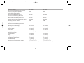
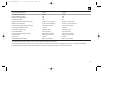
404/504 MANUAL.QXP
7/17/98 11:39 AM
Page 1
404/504 MANUAL.QXP
7/17/98 11:39 AM
Page 2
Table of Contents
Welcome to Club GTi ............................................3
About this Manual .................................................3
Autosound at its Best ............................................3
Designing Your System .........................................5
Coupled ComponentTM Placement.........................5
Installation Warnings and Tips ..............................6
Mounting Instructions ............................................6
Installing the GTi System Crossover .....................6
Woofer/Midrange Driver Mounting ........................7
Mounting Speakers in Custom Locations..............8
Wiring ..................................................................10
System Connections ...........................................10
Crossover Tweeter Level Adjustment..................12
Speaker Break-In ................................................12
A Note on Power Handling ..................................12
In Case of Difficulty .............................................13
Specifications ......................................................14
Thiele-Small Specifications .................................15
2
404/504 MANUAL.QXP
7/17/98 11:39 AM
Page 3
Welcome to Club GTi
About This Manual
Autosound at its Best
Thank you for purchasing the finest
Automotive Coupled ComponentTM
Systems JBL has ever produced. As a
GTi Competition Series owner, you are a
member of a select group of people who
enjoy the most advanced mobile audio
products available. We call this group
“Club GTi.” By sending in the customer
information card, which you will find
attached to your warranty, we will
automatically register you as a Club GTi
member which will give you access to
exclusive Club GTi apparel and other
special offers we will make available from
time to time. We suggest you fill the card
out at your earliest convenience.
Also, be sure to save your sales
receipt in a safe place. It will be necessary
to use this document as proof of purchase
in the event that you ever need warranty
service. It is also useful for insurance
purposes and for establishing value when
you re-sell your vehicle.
Because of the performance capability
of your GTi Competition Series product,
and the variety of potential system
configurations, we strongly recommend
that you have the system professionally
installed. You will also get a better warranty
if your equipment is professionally installed
by an authorized GTi dealer and you have
your warranty card stamped. This manual
provides information on installation and
usage to help a skilled technician get the
most from your GTi Competition Series
product. This manual does not cover basic
information about installation which is
common knowledge to a professional
installer, except for information which is
unique to the 404 and 504GTi systems.
If you feel you possess the necessary
skills, and prefer to install the equipment
yourself, this manual will provide you with
the necessary specifics to properly use the
404 or 504GTi in typical installations.
Consult your JBL dealer, or a qualified
technician, for more information.
The 404 and 504GTi Coupled
ComponentsTM are built to meet the same
rigorous standards of construction and
performance that have long established
JBL’s renowned home and professional
speaker systems. Coupled ComponentsTM
are the first to provide true component
driver quality in a format which mounts
in a single hole. The GTi Coupled
ComponentsTM combine the reference
standard 400 and 500GTi Woofer/Midrange
Drivers with a cantilever mounted 20mm
Pure Titanium tweeter and outboard
2-way crossover. The tweeter is mounted
at a 15° angle which, combined with the
exclusive IntermountTM mounting system,
allows orientation of the speaker for
optimum imaging in any vehicle. The
near-coincident mounting provides the
considerable advantages of equal soundpath length from the woofer and tweeter to
your ear, but without the horn loading
effects that create a distorted midrange in
designs with apex-mounted tweeters.
3
404/504 MANUAL.QXP
7/17/98 11:39 AM
Page 4
The 404 and 504GTi Woofer/Midrange
Drivers incorporate advanced JBL woven
Kevlar cones which are especially suited
to the unique acoustic and environmental
conditions which characterize automotive
sound. The 20mm tweeter incorporates
advanced JBL pure titanium technology
which works extremely well in the
unique acoustic environment of modern
vehicles. The 404 and 504GTi have been
engineered to provide excellent power
handling, good dispersion and balanced
frequency response, along with minimum
size and flexible installation options for
optimizing placement within the vehicle.
Treated Kevlar fiber cones are used
because of their combination of low
weight, high stiffness and resistance to
resonances. The 404 and 504GTi
Woofer/Midranges are topped off with a
treated fabric inverted dome for smooth
reproduction of upper midrange
frequencies.
The cone motion of these high
excursion woofer/midrange designs is
controlled by a Aromatic Polyamid fiber
spider. Because it is 3 times stronger than
4
conventional spider materials, this robust
material is able to control the up to 0.6"
motion of the cone while maintaining
musical accuracy.
The small size of the GTi Woofer/
Midrange Drivers is made possible
through the use of a Neodymium magnet
assembly with JBL’s Stray Field
Containment Geometry. By minimizing
stray magnetic fields, this closed circuit
magnetic assembly design concentrates
the magnetic field on the voice coil where
it provides superior performance. In the
woofer/midrange drivers, this high
concentration of magnetic power is
coupled to a 2" Edge-wound Aluminum
Wire High Temperature Fiberglass Voice
Coil. This coil uses lightweight aluminum
wire to maintain the agility to reproduce
high frequencies while its large diameter
and fiberglass former assures extremely
high thermal power handling. The tweeter
uses Oxygen Free Copper wire immersed
in a thermally conductive bath of viscous
FerrofluidTM. This fluid not only conducts
heat away from the voice-coil to improve
power handling, but damps the
fundamental resonance of the dome for
optimum sound.
The tweeters in the 404 and 504GTi
feature domes made from pure titanium.
Pure titanium has long been known to
have a very high stiffness to weight ratio,
making it ideal for treble reproduction.
However, only JBL has “tamed” titanium
through a special manufacturing process.
The dome of the 404 and 504GTi Tweeter
is created using special nitrogen gas
cooled forming machines which can create
a uniformly paper-thin dome without the
work-hardening or deformation which
causes resonances in domes made
without benefit of this process.
Equally important is the 404 and
504GTi crossover design. Each crossover
was meticulously optimized in JBL’s stateof-the-art acoustic laboratory to guarantee
a seamless blend of the woofer/midrange
and tweeter output. Unlike generic or
general purpose crossovers, the design of
the 404 and 504GTi Crossovers was
performed with a full knowledge of the
performance characteristics of each driver,
allowing frequency, phase, and power
404/504 MANUAL.QXP
7/17/98 11:39 AM
Page 5
response to be completely optimized for
each combination.
What does all this technology add up
to? A Coupled ComponentTM system with
ideal frequency balance, excellent off axis
response, and high output capability in a
small, elegant package. The result is
exceptionally smooth and detailed music
reproduction over the full range of
frequencies and clean sound that cuts
through road noise.
These Coupled ComponentsTM can
be placed in stock locations yet still
deliver the punch and performance of a
component system. The near-coincident,
low profile tweeter mounting and small
size of the driver allow these Coupled
ComponentTM systems to be mounted for
optimum imaging in ways that cannot
easily be achieved with separate
component systems.
Designing Your System
The overall quality of any system
design is a result of how well all of the
components work together, not just the
result of the performance of any one
component. JBL GTi Series woofer/
midbass or subwoofer transducers are
the ideal companion products to your 404
and 504GTi systems. Each of the GTi
Competition Series products are designed
to complement the others to provide the
highest performance with the simplest
and most predictable system design.
To use the 404 and 504GTi as the satellite
transducers in a high quality system,
we recommend you use either a high
quality active crossover such as JBL’s
GTX47, GTX4 or GTX2 to provide
optimum matching to your subwoofer or
woofer/midbass loudspeaker. If you prefer
passive crossovers, we recommend that
you use only high quality audiophile grade
film-type capacitors and Low DCR
inductors to get the most out of your
system. The most popular system
configuration is a hybrid using an active
crossover for the subwoofer to woofer/
midrange crossover point, and the passive
crossover included with your Coupled
ComponentsTM for the woofer/midrange to
tweeter crossover. Your GTi Competition
Series dealer is uniquely qualified to help
guide you on the best system configuration
for your needs.
Coupled Component TM
Placement
The location of each of the
loudspeakers plays a vital role in achieving
proper frequency response and spacious
imaging. The near-coincident design of the
Coupled ComponentsTM gives the 404 and
504GTi systems an extremely wide and
smooth dispersion pattern. As a direct
result, excellent performance may be
achieved in any vehicle. Due to the wide
variety of vehicles, there is more than one
“right” way to locate the 404 and 504GTi.
Knowledge of the following considerations
will help you get the most from your
system:
5
404/504 MANUAL.QXP
1.
2.
3.
4.
7/17/98 11:39 AM
Page 6
The most spacious stereo image is
achieved when the speakers are placed
as wide apart as possible.
The best center image will be achieved
when the distance from the left speaker
to your left ear is as equal as possible
to the distance from the right speaker to
your right ear. This is most easily
achieved by placing the 404 and
504GTi as far forward as you can.
You will get the best frequency
response when the path from the
speakers to your ear is unobstructed.
Because of the high acoustic energy
capability of the 404 and 504GTi, they
must be securely mounted in a rigid
panel which is free from resonances,
rattles and air leakage.
Installation Warnings and Tips
Mounting Instructions
•
Pick a mounting location after reading
the recommendations in the Coupled
Component™ Placement section of this
manual.
•
•
•
•
6
Be careful not to cut or drill into fuel
tanks, fuel lines, brake or hydraulic
lines, vacuum lines or electrical wiring
when working on your vehicle. When
door mounting the speakers, make
sure there is sufficient clearance for
windows, electric window motors or
cranks, and linkages. Inspect behind
panels before you cut or drill.
Be sure to check for clearance of
window, cranks and linkages when
mounting speakers in door panels.
Do not use the speakers unmounted.
Failure to securely mount this product
could result in damage or injury,
particularly in the event of an accident.
Although the materials used on the 404
and 504GTi are inherently water
resistant, do not mount the speakers
where they will get wet.
Always disconnect the ground wire
from the battery before doing any work
on the vehicle.
Installing the GTi System
Crossover
The GTi system crossover should be
mounted securely to prevent damage to
the crossover or possible loosening of
wiring connections. Choose one of the
crossover mounting methods and follow
the directions on the following page.
404/504 MANUAL.QXP
7/17/98 11:39 AM
Page 7
Mounting the GTi Crossover with Wire Ties
1. Remove the crossover cover as
shown in Figure G.
2. Remove the crossover board from the
plastic case.
3. Use wire ties to secure the plastic case
to the desired location as shown in
Figure A.
4. Cut off the excess plastic on the
wire ties.
5. Re-install the PCB and install wiring
from the crossover to the amplifier
and speaker locations as shown in
Figure F.
6. Re-install the crossover cover.
Mounting the Crossover with Screws
1. Remove the crossover cover as
shown in Figure G.
2. Remove the crossover board from
the plastic case.
3. Mark 4 hole locations, drill holes and
secure the bottom cover to the
desired mounting location as shown
in Figure B. Before starting, make
sure no electrical or other critical car
components are located where you
will be drillling.
4. Re-install PCB and install wiring from
the crossover to the amplifier and
speaker locations as shown in Figure F.
5. Re-install the crossover cover.
Figure A
Figure B
Woofer/Midrange Driver
Mounting
Mounting to Stock Hole Locations
1. Access the stock speaker location and
remove the stock speaker. The 404
and 504GTi include IntermountTM
mounting ring adapters which
allow the speaker to be mounted
in standard 4" and 51/4" holes
respectively.
2. Mount the intermount adapter plate to
the stock location using four #8 x 11/4"
screws as shown in Figure C.
3. Attach the foam gasket to the back of
the woofer/midrange. Connect the
speaker wire from the crossover
terminals marked “W” to the
woofer/midrange terminals of the
speaker by either soldering (preferred)
or using crimp terminals. Connect the
“+W” terminal of the crossover to the
orange “W” terminal of the speaker.
Repeat for “–W” terminal.
7
404/504 MANUAL.QXP
4.
5.
6.
7/17/98 11:39 AM
Page 8
Connect the speaker wire from the
crossover terminals marked “T” to the
tweeter terminals of the speaker by
either soldering (preferred) or using
crimp terminals. The “+T” terminal of
the crossover should be connected to
the orange colored T terminal on the
speaker.
The IntermountTM adapter plate has a
series of mounting holes which allow
the coupled component tweeter to be
angled as desired. Pick an orientation
which angles the tweeter in the
desired direction and mount the
woofer/midrange driver to the
IntermountTM adapter ring using three
#8 x 7/16" screws as shown in Figure C.
Replace the stock speaker panels.
INTERMOUNT
ADAPTOR
PLATE
Mounting Speakers in Custom
Locations
1.
Figure C
2.
3.
4.
8
Snap the grill of the speaker onto the
driver and choose three hole locations
so that the tweeter is angled properly
and the grille logo is oriented as desired
for your installation. Use the Fabric
Displacement Ring included in the
package to mark the location of the
three screw holes and the speaker
cutout holes (cutout hole sizes are
listed in Specifications section). Before
cutting or drilling make sure that there
are no car components, electrical wiring
or any other items that could be
damaged.
Cut out the speaker hole at the
mounting location and drill the three
marked pilot holes with a 1/8" (3mm) drill.
Run speaker wire to the hole location,
making sure that either an active or
the included passive crossover is
connected before the speaker.
Put the speaker Fabric Displacement
Ring under the speaker as shown in
Figure D.
404/504 MANUAL.QXP
5.
6.
7.
8.
7/17/98 11:39 AM
Page 9
Connect the speaker wire from the
crossover terminals marked “W” to the
woofer/midrange terminals of the
speaker by either soldering (preferred)
or using crimp terminals. Connect the
“+W” terminal of the crossover to the
orange “W” terminal of the speaker.
Repeat for “–W” terminal.
Attach the foam gasket to the back of
the woofer/midrange. Connect the
speaker wire from the crossover
terminals marked “ T ” to the tweeter
terminals of the speaker by either
soldering (preferred) or using crimp
terminals. The “+T” terminal of the
crossover should be connected to the
orange colored T terminal on the
speaker.
Mount the speaker to the hole location
using three #8 x 11/4" screws as shown
in Figure D.
Push the grille down onto the speaker,
making sure the tabs on the speaker,
match with the slots in the grille. Twist
the grille about 1/2" (12mm) clockwise to
lock the grille into place.
GRILLE
FRAME
FABRIC
DISPLACEMENT
RING
Tab
slot
Figure D
METAL
GRILLE
Figure E
TAB
Note: The metal grille is designed so
that it can be covered with grille cloth if
desired. Simply, remove the metal grille
from the plastic trim ring as shown in
Figure E. Then use spray adhesive to glue
and wrap the grille cloth to the metal grille.
Push the metal grille with cloth back into
the grille frame. For even better interior
matching it is also possible to use plastic
compatible paint to match the grille frame
to the vehicle’s interior.
Logo Orientation on Grille
The orientation of the logo on the
grille relative to the plastic grille ring can
be adjusted. Simply remove the metal
grille and reassemble the metal grille to
the grille frame utilizing a different tab slot.
9
404/504 MANUAL.QXP
7/17/98 11:39 AM
Page 10
Wiring
Use 2-conductor stranded type,
insulated wire to connect the 404 and
504GTi Woofer/Midrange and Tweeter to
the included crossover, and the crossover
to the amplifier as shown in Figure F.
A minimum wire gauge of 18AWG is
recommended, with larger size suggested
for wire runs longer than 10 feet.
TWEETER
WOOFER
INPUT
TWEETER
WOOFER
INPUT
Figure F
10
504 GTI Crossover
The polarity (the positive / negative
orientation of the connections) for every
speaker and crossover to amplifier
connection must be consistent from left to
right channel to assure proper imaging and
optimum frequency response. This does
not mean that the Coupled ComponentsTM
should always be connected in the same
polarity as the woofer/midbass or
subwoofer however. It is possible, due
to the difference in the distance that
the sound travels from the Coupled
Components™ to your ears, compared to
the distance from the subwoofer or
woofer/midbass, and the wavelengths of
sound at the crossover frequency, that a
connection where the subwoofer or
woofer/midbass are connected in reverse
polarity from the Coupled ComponentTM
drivers may actually result in better sound.
Because there is no way to accurately
predict this before installation, we
recommend that you try the connection
both ways, and leave it in the polarity that
gives the smoothest audible transition
between the Coupled Components™ and
the subwoofer or woofer/midbass. Some
active crossovers, such as the JBL GTX47,
have a phase switch which enables you
to easily switch polarity. When the subwoofer or woofer/midbass and Coupled
ComponentsTM are mounted close to each
other, the in-phase connection will usually
yield the best sound.
System Connections
There are a variety of system options
available with the 404 and 504GTi. The
simplest configuration is to use the 404
and 504GTi full range. Although this will
yield good sound, the best performance
will be achieved in a high-end system
which includes subwoofers and, optionally,
midbass transducers. Because the 404
and 504GTi are specifically designed
for mid and high frequency operation,
they should have their extremely low
frequencies blocked by electrical means in
order to achieve the best system fidelity
and the widest dynamic range. However,
full range use may be obtained at slightly
lower power handling levels.
404/504 MANUAL.QXP
7/17/98 11:39 AM
Page 11
For the best performance, we
recommend that an active crossover with
a minimum of 12dB per octave slope be
used for the transition point between the
Subwoofer and the 404 or 504GTi. The
optimum crossover frequency for this
transition is dependent on the specific
components used, the vehicle, and other
installation details. As a general rule, the
crossover frequency should be as low as
possible to achieve the best system
imaging. You can fine-tune the crossover
after the installation is complete for the
best sound. A good place to start your
tuning process is between 50Hz and
150Hz when using the 504GTi and
between 80Hz and 150Hz when using the
404GTi. In 4-way systems using a midbass
driver such as the 600GTi, the crossover
point may be raised higher without
detrimentally affecting imaging as long as
the woofer/midbass drivers can be
mounted reasonably close to the Coupled
ComponentsTM. This higher crossover
frequency will allow the system to play
louder. Since no crossover is perfect, it is
advisable to keep your crossover points
away from the range where your hearing is
most sensitive. Therefore we recommend
that you try to keep the high-pass
frequency below 250Hz. This lets the 404
or 504GTi reproduce the entire range of
frequencies covering the most important
vocal and lead instrument fundamentals
and their harmonics.
If you prefer to use all passive
crossovers, you will need to construct
or purchase a high-pass filter for the
subwoofer to Coupled ComponentTM
transition point and install it in-line ahead
of the 404 or 504GTi Crossover. For
the best system dynamic range, we
recommend that a minimum slope of 12dB
per octave be used.
The most advanced system designs
use active electronic crossovers such as
the JBL GTX2, GTX4 or GTX47 at both the
subwoofer (or woofer/midbass)-to-Coupled
Component™ transition point and at the
woofer/midrange-to-tweeter transition. This
is possible with the coupled component
system because the tweeter and
woofer/midrange are accessible separately
through the individual sets of terminals.
Set the high crossover frequency at or
above 5kHz if a 12dB per octave
crossover is used and at or above 4.5kHz
if you are using an 18 or 24dB per octave
crossover. In this configuration, the
crossovers supplied with the 404 and
504GTi are not used. For tweeter
protection, a 1.5A fast acting fuse should
be installed in series with the tweeter.
The maximum recommended RMS
amplifier power routed directly to the
woofer/midbass driver is 125 watts for the
404GTi and 150 watts for the 504GTi.
When used with the appropriate crossover
and fused as recommended above, the
tweeter can be connected to amplifier
channels of the same power rating
although there is little point in using an
amplifier in excess of 50 watts when
driving the tweeter alone.
11
404/504 MANUAL.QXP
7/17/98 11:39 AM
Page 12
Crossover Tweeter
Level Adjustment
The GTi system crossover allows you
to adjust the level of the GTi systems
tweeter. This adjustment is located under
the crossover cover. To remove this cover
simply press on the end of the cover
(as shown in Figure G) and lift off. The
adjustment of the tweeter level is done by
setting the switch on the crossover (see
Figure H) to the “0dB”, “–2dB” or “–4dB”
position. Set this switch in the position that
matches you personal preference. Both
crossovers should have this switch set in
the same position.
LIFT
PRESS
Figure G
OdB
–2dB
–4dB
Figure H
Speaker Break-In
The 404 and 504GTi woofer/
midranges use many high strength
materials which require benefit from a
break-in period before they will achieve top
performance. After a break-in period of
about 1-hour at moderate volume the
drivers will achieve peak performance.
12
A Note on Power Handling
As a result of their high efficiency, all
JBL loudspeakers will produce reasonable
volume levels in the automotive
environment using very little amplifier
power. However, the use of a low-powered
amplifier to attain very high volume levels
could lead to overdriving the amplifier. This
will generate high distortion levels which
can easily damage loudspeakers, even if
the rated power of the amplifier is below
the rated maximum power handling of the
loudspeaker!
As a general rule, do not turn up the
volume control past the point where you
hear distortion in the form of either signal
distortion from an overdriven amplifier or
mechanical noise from an overstressed
speaker. For the best performance and
system reliability, you should select an
amplifier with an output rating greater than
the maximum power likely to be used to
generate the desired volume levels. If you
want your system “Loud + Clear,” we
suggest that you step up to a JBL power
amplifier which has an RMS power rating
equal to, but not exceeding, the Maximum
Recommended Amplifier Power listed in
the specifications of your specific JBL
speaker. This margin of reserve power will
ensure that the amplifier will not attempt to
deliver more power than its design allows.
Your dealer will be happy to point out
which high power JBL amplifiers are
404/504 MANUAL.QXP
7/17/98 11:39 AM
Page 13
optimum for your application and listening
habits.
Following these guidelines will provide
virtually distortion free sound reproduction
and long loudspeaker life.
In Case of Difficulty
The most common difficulties are
noise, distortion, and intermittent
connections.
System noise is usually not the fault of
the 404 or 504GTi. Hiss or “alternator
whine” is most often the result of faulty
grounding of the system electronics or
improper setting of amplifier level controls.
An exception to this is if the passive
crossover networks are mounted near a
source of radiated noise, the network may
pick-up this noise with sufficient power to
drive the 404 and 504GTi. For this reason,
be careful not to mount any passive
crossovers near wires carrying high
currents such as battery cables or wires
leading to ammeters or tachometers.
Distortion is usually the result of
overdriving one or more components in
the system. The problem is most likely
insufficient amplifier power, or improper
setting of gain controls. Refer to the
instructions which came with the
electronics for assistance. The 404 and
504GTi will not play as loudly, or handle
the full rated power, when used without a
subwoofer and associated high-pass
crossover. When using the 404 or 504GTi
full-range, be careful to limit the volume
level to that which can be reproduced
without audible distortion from the speaker.
If you want to talk to us about any
problems, call JBL Customer Service at
1-800-336-4JBL (4525) between 9AM and
5PM eastern time.
13
404/504 MANUAL.QXP
7/17/98 11:39 AM
Page 14
Specifications:
404GTi
504GTi
Frequency response:
80 – 21kHz
60 – 21kHz
Recommended minimum High-Pass Crossover
Frequency for High Power Operation:
80Hz
50Hz
Continuous Power Handling With 12dB
Passive Network High Passed at
Recommended Minimum Frequency:
85 Watts
120 Watts
Continuous Power Handling When Used
Without High-Pass (Full-Range Operation):
60 Watts
80 Watts
Minimum Recommended Amplifier Power:
20 Watts
20 Watts
Maximum Recommended Amplifier Power Rating:
125 Watts
150 Watts
Sensitivity (2.83 Volts / 1 Meter):
89dB
91dB
Impedance:
4 Ohms
4 Ohms
43/8" (111mm)
51⁄8" (130mm)
Dimensions – Woofer/Midrange Transducers
Overall Maximum Diameter
(Mounting Tab to Frame Edge):
Height:
Mounting Depth:
18
23⁄8" (60mm)
78
21⁄16" (53mm)
34
2 ⁄ " (54mm)
1 ⁄ " (48mm)
Cutout Size:
3 ⁄ " (95mm)
43⁄4" (121mm)
Weight (1 Driver):
1 lb. 9 oz. (0.71kg)
1 lb. 13 oz. (0.82kg)
Dimensions – Tweeter
Overall Diameter:
115⁄16" (50mm)
115⁄16" (50mm)
Height:
11
11
Height With Angle Adapter:
11⁄2" (38mm)
11⁄2" (38mm)
⁄16" (18mm)
⁄16" (18mm)
Flush Mount Cutout Diameter:
21⁄8" (54mm)
21⁄8" (54mm)
Flush Mount Depth:
15
15
Dimensions – Crossover Network (LxWxH):
5 10/16" x 3 3/16" x1 9/16"
5 10/16" x 3 3/16" x 1 9/16"
(143mm x 81mm x 40mm)
(143mm x 81mm x 40mm)
14
⁄16" (23mm)
⁄16" (23mm)
404/504 MANUAL.QXP
7/17/98 11:39 AM
Page 15
Thiele-Small Specifications:
404GTi
504GTi
Free Air Resonance (Fs):
125Hz
100Hz
Electrical Damping (Qes):
0.52
0.51
Mechanical Damping (Qms):
5.17
5.14
Total Damping (Qt):
0.47
0.4
Equivalent Volume of Compilance (Vas):
0.0388 cu. ft. (1.10 liters)
0.1059 cu. ft. (3.0 liters)
Effective Cone Area (Sd):
9.3 sq. inches (0.0060 m2)
14.26 sq. inches (0.0092 m2)
Center to Peak Linear Excursion (Xmax):
0.126 inches (3.2mm)
0.126 inches (3.2mm)
Voice Coil DC Resistance (Re):
3.4 ohms
3.4 ohms
Voice Coil Inductance (Le):
0.22mH @ 1kHz
0.22mH @ 1 kHz
Voice Coil Diameter:
2 inches (51mm)
2 inches (51mm)
Voice Coil Length (Winding Length):
0.400 inches (10.2mm)
0.400 inches (10.2mm)
Air Gap Height:
0.200 inches (5.1mm)
0.200 inches (5.1mm)
BL Product:
6.2 T/M
6.2 T/M
Effective Moving Mass (Mm):
0.28 oz. (8.0 Grams)
0.32 oz. (9.0 Grams)
Note: Specifications apply only after a 2 hour break-in period at medium volume levels.
JBL continually strives to impove its products. New materials, production methods and other refinements may result in a change from published
specifications and description. The changes will equal or exceed the original specifications, unless otherwise stated.
15
404/504 MANUAL.QXP
7/17/98 11:39 AM
Page B
A Harman International Company
NMGP/N:304353-001
5/94