1
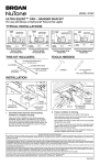
M
E
D
79V / 79W
INSTALLATION INSTRUCTIONS
Single Pole (One location)
4-Speed, Quiet,
Ceiling Fan/Light Control
Fan Control
Rating: 1.5A-120VAC, 60Hz
Full Range Dimming
Incandescent Lamp Load
Rating: 300W-120VAC, 60Hz
INSTALLATION INSTRUCTIONS
99042152D
- Fan will increase or decrease in speed
respectively for desired level.
• Rotate knob control to OFF position
- Fan will turn OFF.
TROUBLESHOOTING
• Fan does not turn ON or does not run
Multispeed
- Circuit breaker or fuse has tripped.
- Fan is not connected to line Neutral.
- Switch on Fan not set to HIGH position.
- Fan and light miswired.
• Light does not turn ON
- Circuit breaker or fuse has tripped.
- Bulb has burned out.
- Lamp is not connected to line Neutral.
- Switch on Fan unit controlling Light is not in
the ON position (if applicable).
- Fan and light miswired.
Figure 1 - Fan Speed Control Functions
TO OPERATE
Dimmer:
• Rotate top knob control clockwise
- Lights will BRIGHTEN accordingly
• Rotate top knob control counter-clockwise
- Lights will DIM accordingly
• Rotate top knob control fully counter-clockwise
- Lights will turn OFF
Fan Speed:
• Rotate bottom knob control to each of the four
levels; MAX, HIGH, MEDIUM, and LOW
Mounting
Strap
Rotary
ON/OFF
Dimmer
X HI M
ED
MA
LO
Rotary
ON/OFF
Fan Speed
Wiring Diagram 1 - Single Location Control Application
Fan Speed/Dimmer
Red (Motor) Hot
Yellow (Light) Hot
Hot (Black)
HI M
E
AX
M
D
Black
LO
BROAN-NUTONE ONE YEAR LIMITED WARRANTY
Broan-NuTone warrants to the original consumer purchaser of its
products that such products will be free from defects in materials or
workmanship for a period of one year from the date of original
purchase. THERE ARE NO OTHER WARRANTIES, EXPRESS OR
IMPLIED, INCLUDING, BUT NOT LIMITED TO, IMPLIED WARRANTIES OF MERCHANTABILITY OR FITNESS FOR A PARTICULAR
PURPOSE.
During this one-year period, Broan-NuTone will, at its option, repair or
replace, without charge, any product or part which is found to be
defective under normal use and service.
THIS WARRANTY DOES NOT EXTEND TO FLUORESCENT LAMP
STARTERS AND TUBES. This warranty does not cover (a) normal
maintenance and service or (b) any products or parts which have been
subject to misuse, negligence, accident, improper maintenance or
repair (other than by Broan-Nutone), faulty installation or installation
contrary to recommended installation instructions.
The duration of any implied warranty is limited to the one-year period
as specified for the express warranty. Some states do not allow
limitation on how long an implied warranty lasts, so the above limitation
may not apply to you.
BROAN-NUTONE’S OBLIGATION TO REPAIR OR REPLACE, AT
BROAN-NUTONE’S OPTION, SHALL BE THE PURCHASER’S SOLE
AND EXCLUSIVE REMEDY UNDER THIS WARRANTY. BROANNUTONE SHALL NOT BE LIABLE FOR INCIDENTAL, CONSEQUENTIAL OR SPECIAL DAMAGES ARISING OUT OF OR IN CONNECTION WITH PRODUCT USE OR PERFORMANCE. Some states do
not allow the exclusion or limitation of incidental or consequential
damages, so the above limitation or exclusion may not apply to you.
This warranty gives you specific legal rights, and you may also have
other rights, which vary from state to state. This warranty supersedes
all prior warranties.
To qualify for warranty service, you must (a) notify Broan-NuTone at
the address or telephone number below, (b) give the model number
and part identification and (c) describe the nature of any defect in the
product or part. At the time of requesting warranty service, you must
present evidence of the original purchase date.
Broan-NuTone LLC, 926 West State Street, Hartford, WI 53027
(1-800-637-1453)
WARNING: TO BE INSTALLED AND/OR USED
IN ACCORDANCE WITH APPROPRIATE
ELECTRICAL CODES AND REGULATIONS.
WARNING: IF YOU ARE NOT SURE ABOUT
ANY PART OF THESE INSTRUCTIONS,
CONSULT A QUALIFIED ELECTRICIAN.
WARNING: TO AVOID OVERHEATING AND
POSSIBLE DAMAGE TO THIS DEVICE AND
OTHER EQUIPMENT, DO NOT INSTALL TO
CONTROL A RECEPTACLE, FLUORESCENT
LIGHTING, A MOTOR- OR A TRANSFORMEROPERATED APPLIANCE OTHER THAN
APPROPRIATE CEILING FANS AND
INCANDESCENT LAMPS.
WARNING: TO REDUCE THE RISK OF FIRE
OR ELECTRICAL SHOCK, THIS CONTROL IS
TO BE USED WITH CEILING FANS THAT ARE
MARKED AS SUITABLE FOR USE WITH A
SOLID-STATE FAN SPEED CONTROL AND IS
RATED 120 VOLTS AC, TOTAL LOAD 1.5
AMPERES MAXIMUM.
WARNING: FOR USE ON CEILING PADDLE
FANS WITH SPLIT-CAPACITOR OR SHADED
POLE MOTORS ONLY. PLEASE REFER TO
FAN MANUFACTURER’S INSTRUCTIONS OR
RATING LABEL ON THE MOTOR TO CONFIRM
TYPE. USE WITH ANY OTHER TYPES OF
MOTORS OR EQUIPMENT MAY CAUSE
OVERHEATING AND/OR DAMAGE TO THE
MOTORS OR EQUIPMENT.
OTHER CAUTIONS:
1. USE ONLY ONE (1) SPEED CONTROL PER
LOAD.
2. DISCONNECT POWER WHEN SERVICING
FIXTURE.
3. USE THIS DEVICE ONLY WITH COPPER OR
COPPER CLAD WIRE. WITH ALUMINUM
WIRE USE ONLY DEVICES MARKED CO/
ALR OR CU/AL.
MULTI-FAN CONTROL:
Any number of fans of the same type may be
controlled by a single fan speed control provided
that the total amperage of the fans do not exceed
the amperage of the fan speed control.
MULTI-GANG INSTALLATION:
There is NO derating necessary for multi-gang
installations of this Quiet Fan/Light Control.
TO INSTALL:
1. WARNING: TO AVOID FIRE, SHOCK, OR
DEATH; TURN OFF POWER AT CIRCUIT
BREAKER OR FUSE AND TEST THAT
POWER IS OFF BEFORE WIRING!
2. Remove existing wallplate and switch, if
applicable.
3. Remove 3/4" (1.9 cm) of insulation from each
circuit conductor. Make sure the ends of wires
are straight.
4. Connect wires per appropriate WIRING
DIAGRAM as follows: Twist strands of each
lead tightly and, with circuit conductors, push
firmly into appropriate wire connector. Screw
connectors on clockwise making sure no bare
wires show below the wire connectors. Secure
each connector with electrical tape.
5. Installation may now be completed by carefully
positioning all wires to provide room in outlet
box for control. Mount control into box with
mounting screws supplied. Attach wallplate.
6. Restore power at circuit breaker or fuse.
Check for proper operation as follows:
Dimmer:
Rotate top knob control clockwise and counterclockwise and ensure that the lights DIM or
BRIGHTEN accordingly.
Fan Speed:
Position the bottom knob to each of the four
levels: MAX, HIGH, MEDIUM and LOW (refer
Figure 1). Ensure that fan speed changes
accordingly.
7. INSTALLATION IS COMPLETE.
FF
O
F
F
M
A
X
HI
FEATURES
• Controls a dimmer and fan in a single gang wall
box
• Four Preset fan levels
• Full range rotary dimming
• Ideal for any area where ceiling fan noise is
distracting
OFF
MODEL
Black
Line
120VAC, 60Hz
Light
Black
Fan
Green
Ground
White
White
Neutral (White)
WIRE CONNECTOR / # OF CONDUCTOR COMBINATION CHART
1- #12 w/ 1 to 3 #14, #16 or #18
2- #12 w/ 1 #14 w/ 1 #16 or #18
2- #12 w/ 1 #16 w/ 1 or 2 #18
2- #14 w/ 1 to 3 #16, #18 or #20
4- #16 w/ 1 or 2 #18, #20 or #22
1- #14 w/ 1 to 4 #16, #18 or #20
2- #14 w/ 1 to 3 #16, #18 or #20
2- #14 w/ 1 #16 w/ 1 or 2 #18 or #20
3- #14 w/ 1 or 2 #18 or #20
4- #14 w/ 1 #16 or #18
2- #16 w/ 1 #18 w/ 1 or 2 #20 or #22
1- #14 w/ 1 #18 w/ 1 to 3 #20
3- #14 w/ 1 #16 w/ 1 #18, #20, #22
3- #14 w/ 1 #18 w/ 1 #20 or #22
M
E
D
79V / 79W
Controls a dimmer and fan in a single gang wall box
Four Preset fan levels
Full range rotary dimming
Ideal for any area where ceiling fan noise is
distracting
INSTRUCCIONES DE INSTALACIÓN
Unipolar (una ubicación)
Control silencioso para lámparas/
ventiladores de cielo raso,
de 4 velocidades
Control para ventiladores
Capacidad nominal: Línea de 1.5 A-120 VCA, 60 Hz
Carga de lámpara incandescente
con reducción de intensidad de
intervalo completo
Capacidad nominal: 300 W-120 VCA, 60 Hz
INSTRUCCIONES DE INSTALACIÓN
• Gire la perilla de control a la posición de APAGADO.
- El ventilador se APAGARÁ.
LOCALIZACIÓN Y RESOLUCIÓN DE PROBLEMAS
• El ventilador no se ENCIENDE o no funciona en múltiples
velocidades
- El disyuntor o el fusible se disparó.
- El ventilador no está conectado a la línea Neutra.
- El conmutador del ventilador no está ajustado en la
posición ALTO.
- El ventilador y la lámpara se conectaron
incorrectamente.
• La luz no se ENCIENDE
- El disyuntor o el fusible se disparó.
- La bombilla se fundió.
- La lámpara no está conectada a la línea Neutra.
- El conmutador de la unidad del ventilador que controla la
lámpara no está en la posición de ENCENDIDO (si es
aplicable).
- El ventilador y la lámpara se conectaron incorrectamente.
Figura 1 - Funciones del control de
velocidad para ventiladores
Conmutador
giratorio de
ENCENDIDO/
APAGADO de
Rotary
la velocidad
del
ON/OFF
ventilador
OPERACIÓN
Cinta
de
Mounting
montaje
Strap
MA
Dimmer
X HI M
ED
Reductor de intensidad:
• Gire hacia la derecha la perilla de control superior
- La intensidad de la luz AUMENTARÁ de manera
correspondiente
• Gire hacia la izquierda la perilla de control superior
- La intensidad de la luz DISMINUIRÁ de manera
correspondiente
• Gire totalmente hacia la izquierda la perilla de control
superior
- Las luces se APAGARÁN.
Velocidad del ventilador:
• Gire la perilla de control inferior a cada uno de los cuatro
niveles: MÁX, ALTO, MEDIO y BAJO
LO
Conmutador
Rotary
giratorio
ON/OFF de
ENCENDIDO/
Fan Speed
APAGADO
del reductor
de intensidad
Diagrama de cableado 1 - Aplicación del control de una ubicación
Velocidad del ventilador/Reductor de intensidad
Rojo (Motor)
(Motor) Vivo
Red
Hot
Amarillo(Light)
(Lámpara)
Vivo
Yellow
Hot
HI M
E
AX
M
Black
Negro
LO
Hot
Vivo(Black)
(negro)
D
GARANTÍA LIMITADA DE UN AÑO DE BROAN-NUTONE
Broan-NuTone garantiza al consumidor comprador original de sus
productos que tales productos estarán libres de defectos en materiales
o mano de obra durante un período de un año a partir de la fecha de la
compra original. NO EXISTEN OTRAS GARANTÍAS, EXPRESAS NI
IMPLÍCITAS, INCLUSIVE, PERO SIN LIMITARSE A, GARANTÍAS
IMPLÍCITAS DE COMERCIALIZACIÓN O IDONEIDAD PARA UN
PROPÓSITO PARTICULAR.
Durante este período de un año, Broan-NuTone, a su criterio, reparará
o reemplazará, sin cargo alguno, cualquier producto o pieza que se
encuentre defectuosa bajo condiciones normales de uso y servicio.
ESTA GARANTÍA NO SE EXTIENDE A ARRANCADORES Y TUBOS
DE LAS LÁMPARAS FLUORESCENTES. Esta garantía no cubre (a)
mantenimiento y servicio normales ni (b) ningún producto o piezas que
se hayan sometido a uso inadecuado, negligencia, accidente,
mantenimiento o reparación inadecuada (no hecha por Broan-Nutone),
instalación incorrecta o instalación en contra de las instrucciones de
instalación recomendadas.
La duración de cualquier garantía implícita se limita al período de un
año como se especifica para la garantía explícita. Algunos estados no
permiten la limitación de la duración de una garantía implícita, de
manera que las limitaciones antedichas pueden no aplicar a usted.
LA OBLIGACIÓN DE BROAN-NUTONE PARA REPARAR O
REEMPLAZAR, A OPCIÓN DE BROAN-NUTONE, SERÁ EL ÚNICO Y
EXCLUSIVO RECURSO DEL COMPRADOR BAJO ESTA GARANTÍA.
BROANNUTONE NO SERÁ RESPONSABLE POR DAÑOS
INCIDENTALES, RESULTANTES O ESPECIALES QUE SURJAN DE
O EN RELACIÓN CON EL USO O RENDIMIENTO DEL PRODUCTO.
Algunos estados no permiten la exclusión o la limitación de daños
incidentales o resultantes, de manera que es posible que la limitación
antedicha no aplique en su caso.
Esta garantía le da derechos legales específicos, y usted puede tener
otros derechos que varían entre estados. Esta garantía sustituye a
todas las garantías anteriores.
Para tener derecho al servicio de la garantía, usted debe (a) notificar a
Broan NuTone a la dirección y número de teléfono que aparecen abajo,
(b) proporcionar el número de modelo y la identificación de la pieza y
(c) describir la naturaleza de cualquier defecto en el producto o pieza.
En el momento de solicitar el servicio de la garantía, debe presentar
comprobante de la fecha de la compra original.
Broan-NuTone LLC, 926 West State Street, Hartford, WI 53027
(1-800-637-1453)
ADVERTENCIA: LA INSTALACIÓN Y/O EL USO
DEBEN HACERSE DE ACUERDO CON LOS
CÓDIGOS Y REGLAMENTOS ELÉCTRICOS
APROPIADOS.
ADVERTENCIA: SI TIENE DUDAS SOBRE
CUALQUIER PARTE DE ESTAS INSTRUCCIONES,
CONSULTE A UN ELECTRICISTA CALIFICADO.
ADVERTENCIA: PARA EVITAR
SOBRECALENTAMIENTO Y POSIBLE DAÑO A ESTE
DISPOSITIVO Y A OTRO EQUIPO, NO LO INSTALE
PARA CONTROLAR UN RECEPTÁCULO, LÁMPARA
FLUORESCENTE, MOTOR O UN
ELECTRODOMÉSTICO OPERADO CON
TRANSFORMADOR, QUE NO SEAN LOS
VENTILADORES DE CIELO RASO Y LAS LÁMPARAS
INCANDESCENTES APROPIADOS.
ADVERTENCIA: PARA REDUCIR EL RIESGO DE
INCENDIO O DESCARGA ELÉCTRICA, ESTE
CONTROL SE DEBE USAR CON VENTILADORES
DE CIELO RASO QUE ESTÉN MARCADOS COMO
ADECUADOS PARA USARSE CON UN CONTROL DE
VELOCIDAD DE ESTADO SÓLIDO PARA
VENTILADORES Y CON CAPACIDAD NOMINAL DE
120 VOLTIOS DE CA, CARGA TOTAL DE 1.5
AMPERIOS COMO MÁXIMO.
ADVERTENCIA: PARA USARSE SOLAMENTE CON
VENTILADORES DE PALETAS DE CIELO RASO CON
CAPACITOR DIVIDIDO O MOTORES DE POLO
SOMBREADO. POR FAVOR CONSULTE LAS
INSTRUCCIONES DEL FABRICANTE DEL
VENTILADOR O LA ETIQUETA INDICADORA DEL
MOTOR PARA CONFIRMAR SU TIPO. EL USO CON
CUALQUIER OTRO TIPO DE MOTORES O EQUIPO
PUEDE CAUSAR SOBRECALENTAMIENTO Y/O
DAÑOS A LOS MOTORES O AL EQUIPO.
OTRAS PRECAUCIONES:
1. USE SÓLO UN (1) CONTROL DE VELOCIDAD
POR CARGA.
2. DESCONECTE LA CORRIENTE ELÉCTRICA
CUANDO DÉ SERVICIO AL APARATO.
3. USE ESTE DISPOSITIVO SÓLO CON ALAMBRES
DE COBRE O ALAMBRES REVESTIDOS DE
COBRE. CON ALAMBRE DE ALUMINIO USE
SÓLO DISPOSITIVOS MARCADOS COMO CO/
ALR O CU/AL.
CONTROL DE MÚLTIPLES VENTILADORES:
Se puede controlar cualquier número de ventiladores del
mismo tipo con un solo controlador de velocidad para
ventiladores, suponiendo que el amperaje total de los
ventiladores no exceda el amperaje del control de
velocidad para ventiladores.
INSTALACIÓN DE MÚLTIPLES ACOPLAMIENTOS:
NO es necesaria la reducción para las instalaciones de
múltiples acoplamientos de este control silencioso para
ventiladores/lámparas.
INSTALACIÓN:
1. ADVERTENCIA: ¡PARA EVITAR INCENDIOS,
DESCARGAS O LA MUERTE, INTERRUMPA LA
ENERGÍA ELÉCTRICA EN EL DISYUNTOR O
FUSIBLE Y COMPRUEBE QUE LA ENERGÍA ESTÁ
INTERRUMPIDA ANTES DE HACER EL
CABLEADO!
2. Quite la placa de pared y el conmutador existentes,
si es aplicable.
3. Quite ¾” (1.9 cm) de aislamiento de cada conductor
de circuito. Asegúrese de que los extremos de los
alambres estén rectos.
- La velocidad del ventilador aumentará o disminuirá
respectivamente según el nivel deseado.
4. Conecte los alambres de acuerdo con el DIAGRAMA DE
CABLEADO apropiado, de la siguiente manera: tuerza
apretadamente los hilos de cada alambre y, con los
conductores de circuito empuje firmemente dentro del
conectador de alambres apropiado. Atornille hacia la
derecha los conectadores asegurándose de que no
aparezcan alambres desnudos debajo de los
conectadores de alambres. Asegure cada conectador con
cinta eléctrica.
5. Ahora se puede completar la instalación colocando
cuidadosamente todos los alambres de manera que se
deje espacio en la caja de salida para el control. Monte el
control en la caja con los tornillos de montaje que se
proporcionan. Instale la placa de pared.
6. Restaure la energía eléctrica en el disyuntor o fusible.
Revise la operación adecuada de la siguiente manera:
Reductor de intensidad:
Gire la perilla de control superior hacia la
derecha y hacia la izquierda y asegúrese de
que la intensidad de las luces DISMINUYA
y AUMENTE de manera correspondiente.
Velocidad del ventilador:
Coloque la perilla inferior en cada uno de
los cuatro niveles: MÁX, ALTO, MEDIO y
BAJO (consulte la Figura 1). Asegúrese
de que la velocidad del ventilador cambie
de manera correspondiente.
7. LA INSTALACIÓN ESTÁ COMPLETA.
FF
O
F
F
M
A
X
HI
CARACTERÍSTICAS
•
•
•
•
OFF
MODELOS
Black
Línea
de
Line
120
VCA, 6060Hz
Hz
120VAC,
Green
Verde
Ground
Tierra
Black
Negro
Lámpara
del
Light
ventilador
Fan
Ventilador
White
Blanco
White
Blanco
Neutro (blanco)
Neutral
(White)
TABLA DE CONECTADORES DE ALAMBRES / # DE COMBINACIONES DE CONDUCTORES
1- #12 w/ 1 a 3 #14, #16 o #18
2- #12 w/ 1 #14 w/ 1 #16 o #18
2- #12 w/ 1 #16 w/ 1 o 2 #18
2- #14 w/ 1 a 3 #16, #18 o #20
4- #16 w/ 1 o 2 #18, #20 o #22
1- #14 w/ 1 a 4 #16, #18 o #20
2- #14 w/ 1 a 3 #16, #18 o #20
2- #14 w/ 1 #16 w/ 1 o 2 #18 o #20
3- #14 w/ 1 o 2 #18 o #20
4- #14 w/ 1 #16 o #18
2- #16 w/ 1 #18 w/ 1 o 2 #20 o #22
1- #14 w/ 1 #18 w/ 1 a 3 #20
3- #14 w/ 1 #16 w/ 1 #18, #20, #22
3- #14 w/ 1 #18 w/ 1 #20 o #22