1
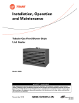
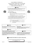
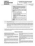
CONTENTS
SAFETY INFORMATION . . . . . . . . . . . . . . . . . 2
FOR YOUR SAFETY . . . . . . . . . . . . . . . . . . . . . . . 2
SYSTEM OPERATION . . . . . . . . . . . . . . . . . . . 2
THERMOSTATS . . . . . . . . . . . . . . . . . . . . . . . . . .
INTERMITTENT IGNITION DEVICE . . . . . . . . . . .
INPUT . . . . . . . . . . . . . . . . . . . . . . . . . . . . . . . . . .
OPERATING INSTRUCTIONS . . . . . . . . . . . . . . .
2
2
3
3
MAINTENANCE . . . . . . . . . . . . . . . . . . . . . . . . 4
GENERAL . . . . . . . . . . . . . . . . . . . . . . . . . . . . . . .
HEATING SYSTEM INSPECTION . . . . . . . . . . . .
LUBRICATION . . . . . . . . . . . . . . . . . . . . . . . . . . . .
AIR FILTERS . . . . . . . . . . . . . . . . . . . . . . . . . . . . .
CONDENSER COIL. . . . . . . . . . . . . . . . . . . . . . . .
BLOWER ASSEMBLY . . . . . . . . . . . . . . . . . . . . . .
BEFORE CALLING A SERVICE PERSON:. . . . . .
4
4
4
4
4
4
4
REPLACEMENT PARTS . . . . . . . . . . . . . . . . .5
USER’S, MAINTENANCE and
SERVICE INFORMATION
MANUAL
S I N G L E PA C K A G E
AIR CONDITIONER
GAS/ELECTRIC
The manufacturer recommends that the “User” read all sections of this manual and
keep the manual for future reference.
FIRE OR EXPLOSION HAZARD
Failure to follow safety warnings exactly could
result in serious injury, death, or property damage.
- Do not store or use gasoline or other flammable vapors and liquids in the vicinity of this or
any other appliance.
- WHAT TO DO IF YOU SMELL GAS:
•Do not try to light any appliance.
•Do not touch any electrical switch; do not use any
phone in your building.
•Leave the building immediately.
•Immediately call your gas supplier from a neighbor’s phone. Follow the gas supplier’s instructions.
•If you cannot reach your gas supplier, call the fire
department.
- Installation and service must be performed by
a qualified installer, service agency or the gas
supplier.
363857-YUM-A-0208
363857-YUM-A-0208
SAFETY INFORMATION
FOR YOUR SAFETY
•
Make sure that the furnace area is clear and free of combustible materials, gasoline and other flammable vapors
and liquids.
Manually moving the thermostat up or down will not speed up
temperature changes in your rooms. This only causes the
thermostat switch to function at your command rather than
responding to room temperature.
Heat generated by devices other than the furnace may interfere with thermostat performance. Therefore, lamps, radios,
television sets, etc. should not be placed near the thermostat.
•
Be sure the furnace is free and clear of insulating material. Examine the furnace area after installation of the furnace or the installation of additional insulation. Some
types of insulation are combustible.
•
For proper operation of this furnace, air for combustion
and ventilation is required. Make sure that these openings are not obstructed.
•
For lighting or shutting down this furnace, refer to the
lighting instructions provided adjacent to the burners and
also located in this manual.
•
A blocked vent roll-out switch is provided in the burner
compartment. This switch is a manual reset. If the furnace fails to operate, contact a qualified service technician.
FIGURE 1 - TYPICAL THERMOSTAT
•
Should the gas supply fail to shut off or if overheating
occurs, shut off the gas valve to the furnace before shutting off the electrical supply. Then call a qualified service
technician.
Your unit is equipped with a cycling spark ignition device. It
has a Relight control designed to automatically light the burners each time the thermostat controller “calls” for heat.
•
Do not use this furnace if any part has been under water.
A flood-damaged furnace is extremely dangerous.
Attempts to use the furnace can result in fire or explosion. A qualified service technician should be contacted
to inspect the furnace and to replace all gas controls,
control system parts, electrical parts that have been wet
or the furnace if deemed necessary.
•
Determine the integrity of the installation regarding the
flue gas vent, the return and supply air duct. Confirm the
equipment is well supported and there are no signs of
deterioration. The manufacturer recommends that main
burner, ignition device and controls are inspected by a
qualified service technician before each heating season.
SYSTEM OPERATION
THERMOSTATS
Set your thermostat for either heating or cooling then set it for
the desired temperature. DO NOT MOVE THE THERMOSTAT RAPIDLY ON AND OFF, OR BACK AND FORTH
FROM HEAT TO COOL. THIS COULD DAMAGE YOUR
EQUIPMENT.
Always allow at least 5 minutes between changes. Find the
temperature that is most comfortable to you, and then LEAVE
YOUR THERMOSTAT ALONE. (Exception is for night or
vacation “set back” to conserve energy).
2
INTERMITTENT IGNITION DEVICE
This furnace is equipped with an intermittent spark and
automatic re-ignition system. Do Not attempt to manually
relight the pilot. Personal injury could result.
When the controller calls for heat, gas is supplied to the Integral Crossover Burners and at the same time, sparking
occurs to light the main burner gas. A flame sensor closes a
circuit to the ignitor control which proves that all of the burners have ignited properly.
On initial start-up, air may be in the gas lines. Several tries for
ignition may be required before the gas will carry over and
the heat sections remains lit. The ignition model has 3 trials
for ignition. If the ignition module locks out, it may be necessary to remove re-establish the call for heat W1 or W2 to continue the purging process.
When the controller is satisfied, the electrical circuit to the
gas valve is opened, closing off the flow of gas to the main
burner.
If the burners should fail to light, contact your heating contractor or gas company for service to insure that proper operating conditions are restored.
In the event that gas to the main burner has been shut-off,
DO NOT attempt to place the furnace into operation. Call the
appropriate service agency.
Johnson Controls Unitary Products
363857-YUM-A-0208
INPUT
The correct heat capacity of the furnace is regulated by the
main burner orifices and the gas pressure. The proper orifices for natural gas are furnished but the gas pressure regulator must be adjusted by the installer or gas company
service person.
OPERATING INSTRUCTIONS
TO SHUT DOWN THE FURNACE:
1.
Close the main gas shutoff valve(s).
2.
Turn off the electric power supply.
HEAT EXCHANGER TUBE
GAS
SUPPLY
PIPE
BURNER
BURNER BRACKET
IGNITOR
BURNER FLAME
(BLUE ONLY)
FIGURE 2 - TYPICAL FLAME APPEARANCE
EXHAUST VENT OUTLET
TO LIGHT THE FURNACE:
1.
Do not attempt to light manually.
2.
Open the main gas shutoff valve(s).
3.
Turn on the electric power supply.
4.
Initiate a call for heat.
5.
If the return air temperature is below the set point of the
controller, the ventor fans will operate. After an adequate
purge time, the intermittent ignition device will light the
burners. The burners will extinguish and relight automatically upon the demand of the controller.
SHIPPING LABELS
(REMOVE SHIPPING
LABELS PRIOR TO
VENT INSTALLATION)
VENT FLUE ASSY.
VENT SAFETY SYSTEM
Each gas furnace module is equipped with an automatic
reset high temperature limit and rollout switch. In the unlikely
event of a sustained main burner flame rollout, the switch will
shut off the flow of gas by closing the main gas valve. The
ignition module will also be disabled, preventing the flow of
gas to the valve. The rollout switch for each module is located
inside the gas heat section access door on the heat shield of
each module. Flame rollout can be caused by blockage of the
power vent system or improper gas pressure adjustment. If
this occurs the furnace will not operate properly, gas supply
to the furnace should be shut off and no attempt should be
made to place the furnace in operation. The system should
be inspected by a qualified service person. Refer to Figure 3
for a typical installation of vent hoods.
The ignition modules are designed such that if the furnace
fails to ignite after 3 trials for ignition after a call for heat the
flow of gas will be shut off and the ignition module will lock out
for one hour. Then the modules will retry ignition and repeat
cycle until ignition occurs, or call for heat is satisfied or power
to unit is removed. If the furnace does not light after several
tries, a service man should be called to determine the cause
of the problem.
COMBUSTION AIR INLET
HEAT SECTION DOOR
FIGURE 3 - FLUE VENT ASSEMBLY
This furnace is equipped with a blocked vented shut-off system (air proving switch). The purpose of the switch is to prove
that there is combustion air being drawn through the heat
section. The ignition control will not operate if this switch is
not made in the pre-purge time of the vent assembly. In the
event that the furnace fails to operate due to the pressure
switch, a qualified service agency should be contacted.
Determine that external vent is in place (field installed) and
clear and free of obstructions.
FILTER CHANNEL
PERIMETER FRAME
FILTERS
EXTERNAL
UPRIGHT
FILTER
BRACKET
EXTERNAL
UPRIGHT
FILTERS
FILTER CHANNEL
BASE RAIL
FIGURE 4 - FILTER ACCESS
Johnson Controls Unitary Products
3
363857-YUM-A-0208
MAINTENANCE
GENERAL
Snow or debris should not be allowed to accumulate in or
around the unit. Do not permit overhanging structures or
shrubs to obstruct condenser air discharge, combustion air
inlets or vent air outlets on your unit. Adequate air is important to the safe and proper operation of the unit.
Prior to any of the following maintenance procedures, shut off all power to the unit.
HEATING SYSTEM INSPECTION
It is the owner's responsibility to insure that an annual inspection of the entire heating portion of the unit is made by a qualified service agency. This should include inspection of the
burners, tubes and flue for any corrosion or soot accumulation which may require cleaning and also checking of burners
and controls for proper operation.
All other fans and motors should be lubricated per schedule
in MAINTENANCE SECTION in the UNIT INSTALLATION
INSTRUCTION.
AIR FILTERS
NOTE: For hi-efficiency rigid or bag filters, consult manufacturers manual.
Filters must always be used. They should be inspected once
a month and thoroughly cleaned or replaced if it appears they
are beginning to accumulate excessive dirt. Filter sizes and
quantities are shown in the following table.
To install the filters, open the filter access door.
Slide the dirty filters out and slide the clean filters all the way
into the filter racks provided (see Fig. 4). They must butt each
other when sliding into position. Close the filter access door.
NOTE: Filters must be installed with “Air Flow” arrows pointing toward the evaporator coil. They must also be
re-installed in their original position without any gaps
between filters.
CONDENSER COIL
In addition, at least once during the heating season, the
owner shall make a visual inspection of the flue or vent air
outlets for evidence of black soot or blockage by leaves or
other debris. If any soot is found it is recommended a qualified service agency be called immediately. Also clear any
blockage found around either the vent air hoods or combustion air inlets.
An annual check and cleaning, if necessary, of the condenser
coil should be done. Clean any debris and dirt from the outside coil face with a brush being careful not to damage the
fins. If extremely dirty, a hose can be used to wash the coil
from the inside out while brushing a soapy solution on the
outside.
Check for obvious signs of deterioration of the furnace.
Check that the return and supply ducts attached to the unit
are sound and air tight without sagging cracks or gaps.
Check that the unit's physical support, or roof curb, is sound
and not in need of repair. Make sure there are no gaps
between the roof curb and the unit where rain could leak.
BLOWER ASSEMBLY
Start the furnace. The ventor motors should start and after a
short delay the main burners should ignite. If they do not,
contact a qualified service person for assistance. Check the
appearance of each main burner flame. The flame should
have a blue appearance. No yellow flame should be
observed. A yellow flame indicates a problem with the combustion system or that cleaning is required.
LUBRICATION
Even with good filters properly in place, blower wheels and
motors will become dust laden after long months of operation.
The entire blower assembly should be inspected annually. If
the motor and/or the blower wheel are heavily coated with
dust, they can be brushed and cleaned with a vacuum
cleaner.
BEFORE CALLING A SERVICE PERSON:
A.
Check controller setting and insure it is calling for heating or cooling.
B.
Check fuses or circuit breakers.
C.
Check filters for excessive dust accumulation.
Outdoor fan and ventor motors are permanently lubricated.
Lubrication is not recommended.
4
Johnson Controls Unitary Products
363857-YUM-A-0208
TABLE 1: FILTERS
FILTER
2 Hi Eff. TA
2 Pleated, 65%
65% Rigid w/2 TA Prefilters
95% Rigid w/2 TA Prefilters
25 TON
4 ea. 16 x 25 / 6 ea. 20 x 25
4 ea. 16 x 25 / 6 ea. 20 x 25
4 ea. 16 x 25 / 6 ea. 20 x 25
4 ea. 16 x 25 / 6 ea. 20 x 25
QUANTITY PER UNIT AND SIZE
30 TON
4 ea. 16 x 25 / 6 ea. 20 x 25
4 ea. 16 x 25 / 6 ea. 20 x 25
4 ea. 16 x 25 / 6 ea. 20 x 25
4 ea. 16 x 25 / 6 ea. 20 x 25
40 TON
4 ea. 16 x 25 / 6 ea. 20 x 25
4 ea. 16 x 25 / 6 ea. 20 x 25
4 ea. 16 x 25 / 6 ea. 20 x 25
4 ea. 16 x 25 / 6 ea. 20 x 25
REPLACEMENT PARTS
Contact your local York® parts distribution center for
authorized replacement parts.
Johnson Controls Unitary Products
5
363857-YUM-A-0208
6
Johnson Controls Unitary Products
363857-YUM-A-0208
Johnson Controls Unitary Products
7
Subject to change without notice. Printed in U.S.A.
Copyright © 2008 by Johnson Controls, Inc. All rights reserved.
Johnson Controls Unitary Products
5005 York Drive
Norman, OK 73069
363857-YUM-A-0208
Supersedes: Nothing