1
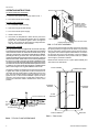
USER’S INFORMATION MANUAL MILLENNIUM® ROOFTOPS SINGLE PACKAGE UNIT WITH GAS - ELECTRIC - HOT WATER Y13, Y14 Supersedes: Nothing 530.70-O1Y (397) 035-15384 WARNING: If the information in this manual is not followed exactly, a fire or explosion may result causing property damage, personal injury or loss of life. – Do not store or use gasoline or other flammable vapors and liquids in the vicinity of this or any other appliance. – WHAT TO DO IF YOU SMELL GAS: • Do not try to light any appliance. • Do not touch any electrical switch; do not use any phone in your building. • Immediately call your gas supplier from a neighbor’s phone. Follow the gas supplier’s instructions. • If you cannot reach your gas supplier, call the fire department. – Installation and service must be performed by a qualified installer, service agency or the gas supplier. WARNING: Should overheating occur, or the gas supply fail to shut off, shut off the manual gas valve to the appliance BEFORE shutting off the electrical supply. CAUTION: The furnace area must be kept clear and free of combustible materials, gasoline and other flammable vapors and liquids. For proper and safe operation , the furnace needs air for combustion and ventilation. DO NOT block or obstruct air openings on the furnace, air openings communicating with the area in which the furnace is installed and the spacing around the furnace. The flow of combustion and ventilation air must not be obstructed from entering the furnace or condenser coil. Do not permit overhanging structures or shrubs to obstruct condenser fan discharge, combustion air inlet or vent outlet. Do not use this furnace if any part has been under water. Immediately call a qualified service technician to inspect the furnace and to replace any part of the control system and any gas control which has been under water. Your outdoor heating / cooling package unit is a valuable piece of equipment, designed and manufactured by the most modern method. Proper care of your unit should result in many years of service and comfort. Annual check-up of your unit by a qualified service person is recommended. FURNACE OPERATION INTERMITTENT IGNITION DEVICE Your unit is equipped with a cycling spark ignition device. It has a Relight control designed to automatically light the burners each time the controller “calls” for heat. CAUTION: This furnace is equipped with an intermittent spark and automatic re-ignition system. Do Not attempt to manually re-light the burners. Personal injury could result. When the controller calls for heat, gas is supplied to the Integral Crossover Burners and at the same time, sparking occurs to light the main burner gas. A flame sensor closes a circuit to the ignitor control which proves that all of the burners have ignited properly. On initial start-up, air may be in the gas lines. Several trys for ignition maybe required before the gas will carry over and the heat sections remains lit. The ignition model has 3 trials for ignition. If the ignition module locks out, it may be necessary to remove re-establish the call for heat W1 or W2 to continue the purging process. When the controller is satisfied, the electrical circuit to the gas valve is opened, closing off the flow of gas to the main burner. If the burners should fail to light, contact your heating contractor or gas company for service to insure that proper operating conditions are restored. In the event that gas to the main burner has been shut-off, DO NOT attempt to place the furnace into operation. Call the appropriate service agency. INPUT The correct heat capacity of the furnace is regulated by the main burner orifices and the gas pressure. The proper orifices for natural gas are furnished but the gas pressure regulator must be adjusted by the installer or gas company service person. 530.70-O1Y OPERATING INSTRUCTIONS EXHAUST VENT OUTLET TO SHUT DOWN THE FURNACE: 1. Close the main gas shutoff valve(s). Refer to FIG. 1. 2. Turn off the electric power supply. TO LIGHT THE FURNACE: SHIPPING LABELS (REMOVE SHIPPING LABELS PRIOR TO VENT INSTALLATION) 1. Do not attempt to light manually. 2. Open the main gas shutoff valve(s). 3. Turn on the electric power supply. 4. Initiate a call for heat. 4. If the return air temperature is below the set point of the controller, the ventor fans will operate. After an adequate purge time, the intermittent ignition device will light the burners. The burners will extinguish and relight automatically upon the demand of the controller. VENT SAFETY SYSTEM Each gas furnace module is equipped with an automatic reset high temperature limit and rollout switch. In the unlikely event of a sustained main burner flame rollout, the switch will shut off the flow of gas by closing the main gas valve. The ignition module will also be disabled, preventing the flow of gas to the valve. The rollout switch for each module is located inside the gas heat section access door on the heat shield of each module. Flame rollout can be caused by blockage of the power vent system or improper gas pressure adjustment. If this occurs the furnace will not operate properly, gas supply to the furnace should be shut off and no attempt should be made to place the furnace in operation. The system should be inspected by a qualified service person. Refer to Figure 2 for a typical installation of vent hoods. VENT FLUE ASSY. HEAT SECTION DOOR COMBUSTION AIR INLET FIG. 1 - FLUE VENT ASSEMBLY This furnace is equipped with a blocked vented shut-off system (air proving switch). The purpose of the switch is to prove that there is combustion air being drawn through the heat section. The ignition control will not operate if this switch is not made in the pre-purge time of the vent assembly. In the event that the furnace fails to operate due to the pressure switch, a qualified service agency should be contacted. Determine that external vent is in place (field installed) and clear and free of obstructions. FILTER CHANNEL The ignition modules are designed such that if the furnace fails to ignite after 3 trials for ignition after a call for heat the flow of gas will be shut off and the ignition module will lock out for one hour. Then the modules will retry ignition and repeat cycle until ignition occurs, or call for heat is satisfied or power to unit is removed. If the furnace does not light after several tries, a service man should be called to determine the cause of the problem. PERIMETER FRAME FILTERS EXTERNAL UPRIGHT HEAT EXCHANGER TUBE GAS SUPPLY PIPE BURNER BURNER BRACKET IGNITOR FILTER BRACKET EXTERNAL UPRIGHT FILTERS BURNER FLAME (BLUE ONLY) FILTER CHANNEL BASE RAIL FIG. 3 - Filter Access FIG. 2 - TYPICAL FLAME APPEARANCE 2 York International Corporation 530.70-O1Y MAINTENANCE GENERAL AIR FILTERS Snow or debris should not be allowed to accumulate in or around the unit. Do not permit overhanging structures or shrubs to obstruct condenser air discharge, combustion air inlets or vent air outlets on your unit. Adequate air is important to the safe and proper operation of the unit. NOTE: For hi-efficiency rigid or bag filters, consult manufacturers manual. WARNING: Prior to any of the following maintenance procedures, shut off all power to the unit. HEATING SYSTEM INSPECTION It is the owner’s responsibility to insure that an annual inspection of the entire heating portion of the unit is made by a qualified service agency. This should include inspection of the burners, tubes and flue for any corrosion or soot accumulation which may require cleaning and also checking of burners and controls for proper operation. In addition, at least once during the heating season, the owner shall make a visual inspection of the flue or vent air outlets for evidence of black soot or blockage by leaves or other debris. If any soot is found it is recommended a qualified service agency be called immediately. Also clear any blockage found around either the vent air hoods or combustion air inlets. Check for obvious signs of deterioration of the furnace. Check that the return and supply ducts attached to the unit are sound and air tight without sagging cracks or gaps. Check that the unit’s physical support, or roof curb, is sound and not in need of repair. Make sure there are no gaps between the roof curb and the unit where rain could leak. Start the furnace. The ventor motors should start and after a short delay the main burners should ignite. If they do not, contact a qualified service person for assistance. Check the appearance of each main burner flame. The flame should have a blue appearance. No yellow flame should be observed. A yellow flame indicates a problem with the combustion system or that cleaning is required. LUBRICATION Outdoor fan and ventor motors are permanently lubricated . Lubrication is not recommended. All other fans and motors should be lubricated per schedule in MAINTENANCE SECTION in the UNIT INSTALLATION INSTRUCTIONS (Form 530.70-N1Y) Filters must always be used. They should be inspected once a month and thoroughly cleaned or replaced if it appears they are beginning to accumulate excessive dirt. Filter sizes and quantities are shown in the following table. To install the filters, open the filter access door. Slide the dirty filters out and slide the clean filters all the way into the filter racks provided (see Fig. 4). They must butt each other when sliding into position. Close the filter access door. NOTE: Filters must be installed with “Air Flow” arrows pointing toward the evaporator coil. They must also be re-installed in their original position without any gaps between filters. CONDENSER COIL An annual check and cleaning, if necessary, of the condenser coil should be done. Clean any debris and dirt from the outside coil face with a brush being careful not to damage the fins. If extremely dirty, a hose can be used to wash the coil from the inside out while brushing a soapy solution on the outside. BLOWER ASSEMBLY Even with good filters properly in place, blower wheels and motors will become dust laden after long months of operation. The entire blower assembly should be inspected annually. If the motor and/or the blower wheel are heavily coated with dust, they can be brushed and cleaned with a vacuum cleaner. BEFORE CALLING A SERVICE PERSON: A. Check controller setting and insure it is calling for heating or cooling. B. Check fuses or circuit breakers. C. Check filters for excessive dust accumulation. FILTERS Filters QUANTITY PER UNIT AND SIZE 30 TON 40 TON 2" Hi Eff. TA 4 ea 16 x 25 / 6 ea. 20 x 25 x 30.4 4 ea 16 x 25 / 6 ea. 20 x 25 x 30.4 2" Pleated, 65% 4 ea 16 x 25 / 6 ea. 20 x 25 x 30.4 4 ea 16 x 25 / 6 ea. 20 x 25 x 30.4 65% Rigid w/2" TA Prefilters 4 ea 16 x 25 / 6 ea. 20 x 25 x 30.4 4 ea 16 x 25 / 6 ea. 20 x 25 x 30.4 95% Rigid w/2" TA Prefilters 4 ea 16 x 25 / 6 ea. 20 x 25 30.4 4 ea 16 x 25 / 6 ea. 20 x 25 30.4 York International Corporation 3 OWNER please have your installer fill in the following information immediately after unit has been installed and properly operating. Installed by ___________________________________________________________________________________________ Installer’s Address ______________________________________________________________________________________ Installation Date _______________________________________________________________________________________ Owner’s Name ________________________________________________________________________________________ Owner’s Address _______________________________________________________________________________________ Equipment installed at (address)___________________________________________________________________________ Model Number______________________________________ Serial Number _____________________________________ Company from whom the equipment was purchased ___________________________________________________________ The owner should keep this information in a place where it can be found if needed for warranty purposes. Unitary Products Group P.O. Box 1592, York, Pennsylvania USA 17405-1592 Subject to change without notice. Printed in U.S.A Copyright by York International Corporation 1997. All Rights Reserved. SHU M .44 Code: EBY, SBY 530.70-O1Y (397)