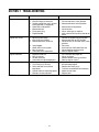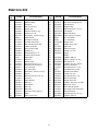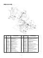
1
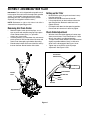
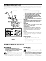
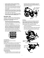
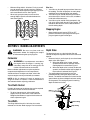
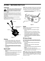
OPERATOR’S MANUAL
Front Tine Tiller
Model 030
IMPORTANT: Read safety rules and instructions carefully before operating equipment.
Warning: This unit is equipped with an internal combustion engine and should not be used on or near any unimproved forestcovered, brush-covered or grass-covered land unless the engine’s exhaust system is equipped with a spark arrester meeting
applicable local or state laws (if any). If a spark arrester is used, it should be maintained in effective working order by the operator.
In the State of California the above is required by law (Section 4442 of the California Public Resources Code). Other states may have
similar laws. Federal laws apply on federal lands. A spark arrester for the muffler is available through your nearest engine authorized
service dealer or contact the service department, P.O. Box 368022 Cleveland, Ohio 44136-9722.
MTD PRODUCTS INC. P.O. BOX 368022 CLEVELAND, OHIO 44136-9722
PRINTED IN U.S.A.
FORM NO. 770-10473.fm
(1/2001)
TABLE OF CONTENTS
Content
Page
Important Safe Operation Practices................................................................... 3
Assembling Your Tiller ....................................................................................... 5
Know Your Tiller................................................................................................. 6
Operating Your Tiller.......................................................................................... 7
Making Adjustments .......................................................................................... 9
Maintaining Your Tiller ....................................................................................... 10
Troubleshooting ................................................................................................. 11
Parts List............................................................................................................ 12
FINDING MODEL NUMBER
This Operator’s Manual is an important part of your new tiller. It will help you assemble, prepare and
maintain the unit for best performance. Please read and understand what it says.
Before you start assembling your new equipment, please locate the model plate on the
equipment and copy the information from it in the space provided below. The information on
the model plate is very important if you need help from our Customer Support Department or
an authorized dealer.
•
You can locate the model number by looking down at the rear of the tiller. A sample model plate is
explained below. For future reference, please copy the model number and the serial number of the
equipment in the space below.
(Model Number)
(Serial Number)
Copy the model number here:
Copy the serial number here:
MTD PRODUCTS INC
CLEVELAND, OHIO 44136
CALLING CUSTOMER SUPPORT
If you have difficulty assembling this product or have any questions regarding the controls, operation or
maintenance of this unit, please call the Customer Dealer Referral Line.
Call 1- (330) 220-4MTD (4683) or 1- (800)-800-7310 to reach a Customer Support
representative. Please have your unit’s model number and serial number ready when you
call. See previous section to locate this information. You will be asked to enter the serial
number in order to process your call.
2
SECTION 1: IMPORTANT SAFE OPERATION PRACTICES
WARNING: This symbol points out important safety instructions which, if not followed, could
endanger the personal safety and/or property of yourself and others. Read and follow all instructions in
this manual before attempting to operate this machine. Failure to comply with these instructions may
result in personal injury. When you see this symbol— heed its warning.
WARNING: Engine exhaust, some of its constituents, and certain vehicle components contain or
emit chemicals known to State of California to cause cancer and birth defects or other reproductive
harm
DANGER: This machine was built to be operated according to the rules for safe operation in this
manual. As with any type of power equipment, carelessness or error on the part of the operator can
result in serious injury. This machine is capable of amputating hands and feet. Failure to observe the
following safety instructions could result in serious injury or death.
Training
1.
2.
3.
4.
5.
7.
8.
Read, understand, and follow all instructions on the
machine and in the manual(s) before attempting to
assemble and operate. Keep this manual in a safe
place for future and regular reference and for
ordering replacement parts.
Be familiar with all controls and their proper
operation. Know how to stop the machine and
disengage them quickly.
Never allow children under 14 years old to operate
this machine. Children 14 years old and over should
read and understand the operation instructions and
safety rules in this manual and should be trained
and supervised by a parent.
Never allow adults to operate this machine without
proper instruction.
Keep bystanders, helpers, pets and children at least
75 feet from the machine while it is in operation.
Stop machine if anyone enters the area.
9.
10.
11.
12.
13.
14.
15.
16.
Use only an approved gasoline container.
Extinguish all cigarettes, cigars, pipes and other
sources of ignition.
Never fuel machine indoors.
Never remove gas cap or add fuel while the engine
is hot or running.
Allow engine to cool at least two minutes before
refueling.
Never over fill fuel tank. Fill tank to no more than ½
inch below bottom of filler neck to provide space for
fuel expansion.
Replace gasoline cap and tighten securely.
If gasoline is spilled, wipe it off the engine and
equipment. Move machine to another area. Wait 5
minutes before starting the engine.
Never store the machine or fuel container inside
near an open flame, spark or pilot light (e.g.
furnace, water or space heater, clothes dryer etc.).
Allow machine to cool 5 minutes before storing.
Preparation
Operation
1.
1.
2.
3.
4.
5.
6.
Thoroughly inspect the area where the equipment is
to be used. Remove all stones, sticks, wire, and
other foreign objects which could be tripped over
and cause personal injury.
Wear sturdy, rough-soled work shoes and close
fitting slacks and shirt. Loose fitting clothes or
jewelry can be caught in movable parts. Never
operate this machine in bare feet or sandals.
Disengage clutch levers and shift (if provided) into
neutral (“N”) before starting the engine.
Never leave this machine unattended with the
engine running.
Never attempt to make any adjustments while
engine is running, except where specifically
recommended in the operator’s manual.
To avoid personal injury or property damage use
extreme care in handling gasoline. Gasoline is
extremely flammable and the vapors are explosive.
Serious personal injury can occur when gasoline is
spilled on yourself or your clothes which can ignite.
Wash your skin and change clothes immediately.
2.
3.
4.
5.
6.
7.
8.
3
Do not put hands or feet near rotating parts. Contact
with the rotating parts can amputate hands and feet.
Do not operate machine while under the influence
of alcohol or drugs.
Never operate this machine without good visibility
or light. Always be sure of your footing and keep a
firm hold on the handles.
Keep bystanders, helpers, pets, and children at
least 75 feet from the machine while it is in
operation. Stop the machine if anyone enters the
area.
Be careful when tilling in hard ground. The tines
may catch in the ground and propel the tiller
forward. If this occurs, let go of the handle bars and
do not restrain the machine.
Exercise extreme caution when operating on or
crossing gravel surfaces. Stay alert for hidden
hazards or traffic. Do not carry passengers.
Never operate the machine at high transport
speeds on hard or slippery surfaces.
Exercise caution to avoid slipping or falling.
9.
10.
11.
12.
13.
14.
15.
16.
17.
18.
19.
20.
21.
Look down and behind and use care when in
reverse or pulling machine towards you.
Start the engine according to the instructions found
in this manual and keep feet well away from the
tines at all times.
After striking a foreign object, stop the engine,
disconnect the spark plug wire and ground against
the engine. Thoroughly inspect the machine for any
damage. Repair the damage before starting and
operating.
Disengage all clutch levers and stop engine before
you leave the operating position (behind the
handles). Wait until the tines come to a complete
stop before unclogging the tines, making any
adjustments, or inspections.
Never run an engine indoors or in a poorly
ventilated area. Engine exhaust contains carbon
monoxide, an odorless and deadly gas.
Muffler and engine become hot and can cause a
burn. Do not touch.
Use caution when tilling near fences, buildings and
underground utilities. Rotating tines can cause
property damage or personal injury.
Do not overload machine capacity by attempting to
till soil to deep at to fast of a rate.
If the machine should start making an unusual noise
or vibration, stop the engine, disconnect the spark
plug wire and ground it against the engine. Inspect
thoroughly for damage. Repair any damage before
starting and operating.
Keep all shields, guards and safety devices in place
and operating properly.
Never pick up or carry machine while the engine is
running.
Use only attachments and accessories approved by
the manufacturer. Failure to do so, can result in
personal injury.
If situations occur which are not covered in this
manual, use care and good judgment. Contact your
dealer or telephone 1-800-800-7310 for assistance
and the name of your nearest servicing dealer.
3.
4.
5.
6.
7.
8.
9.
10.
Your Responsibility
1.
2.
Maintenance & Storage
1.
2.
Before cleaning, repairing, or inspecting, stop the
engine and make certain the tines and all moving
parts have stopped. Disconnect the spark plug wire
and ground it against the engine to prevent
unintended starting.
Do not change the engine governor settings or overspeed the engine. The governor controls the
maximum safe operating speed of the engine.
Maintain or replace safety and instruction labels, as
necessary.
Follow this manual for safe loading, unloading,
transporting, and storage of this machine.
Never store the machine or fuel container inside
where there is an open flame, spark or pilot light
such as a water heater, furnace, clothes dryer etc.
Always refer to the operator’s manual for proper
instructions on off-season storage.
If the fuel tank has to be drained, do this outdoors.
Observe proper disposal laws and regulations for
gas, oil, etc. to protect the environment.
Never tamper with safety devices. Check their
proper operation regularly.
Check bolts and screws for proper tightness at
frequent intervals to keep the machine in safe
working condition. Also, visually inspect machine for
any damage.
4
Restrict the use of this power machine to persons
who read, understand and follow the warnings and
instructions in this manual and on the machine.
The safety label on the tiller is reproduced below for
your review. To ensure safe operation of the tiller,
follow the instructions on all labels closely.
SECTION 2: ASSEMBLING YOUR TILLER
Setting up the Tiller
IMPORTANT: This unit is shipped without gasoline or oil
in the engine. Be certain to service engine with gasoline
and oil, as instructed in the engine manual, before
operating your tiller. (The engine manual is packed
seperately and shipped in the tiller carton.)
•
•
•
NOTE: Reference to right or left side of the tiller is
observed from the operating position.
•
Removing Unit From Carton
•
•
•
Remove staples, break glue on top flaps, or cut
tape at carton end and peel along top flap to open
carton. Remove loose parts (i.e., operator’s
manual, etc.) from carton.
Cut along corners, lay carton down flat, and remove
packing material. Roll or slide unit out of carton and
check carton thoroughly again before discarding.
Extend control cables to the rear of the tiller and lay
them on the floor. Do not bend or kink cables.
Disconnect the spark plug wire and move it away
from the spark plug.
Remove the handle lever from the handle.
Lift up and pull back on the handle to raise to the
operating position. Reinsert handle lever and
tighten securely.
Pull depth stake down into the operating position.
Please refer to instructions in detail on page 8.
Check Cable Adjustment
•
•
•
With the clutch lever disengaged, pull starter rope
slowly several times. Tines should not turn. If tines
do turn, the cable is not adjusted properly.
To adjust cable, loosen bottom nut at cable bracket
slightly to provide additional slack in cable wire
while clutch is disengaged. See Figure 1 inset.
Tighten top nut and check again for proper
adjustment. See Figure 1 inset.
Tine Clutch
Control Lever
Lift
handle
up
Clutch Cable
Handle
Lever
Top Hex Nut
Cable
Bracket
Bottom
Hex Nut
Depth Stake
Figure 1
5
SECTION 3: KNOW YOUR TILLER
Read this operator’s manual and safety rules before operating your tiller. Compare the illustrations in Figure 2 with
your tiller to familiarize yourself with the location of various controls and adjustments. Save this manual for future
reference.
Throttle Control
The throttle control lever is located on the engine. It
controls the engine’s speed and stops the engine.
• With the throttle control pushed completely to the
right, the carburetor is in START or FAST position.
Use maximum engine speed for deep tilling.
• Pull the throttle control back to reduce engine
speed to IDLE. Throttle control should be at IDLE
for transporting the tiller.
• Pull the throttle completely back to stop the engine.
Tine Clutch
Handle
Assembly
Spark
Plug
Handle
Lever
Recoil Starter
Choke Lever
The choke lever is located near the throttle control. It is
used to enrich the fuel mixture when starting a cold
engine.
Tine
Shield
Depth
Stake
Starter Handle
The starter handle is located on the engine and is
used to manually start the engine.
Tine Clutch Control
Tines
The clutch control lever is located on the left handle.
Squeezing the lever against the handle engages the
tine drive. Release the lever to stop the tines from
turning.
Choke
Depth Stake
The depth stake is located in the rear of the tiller and it
controls the tilling depth. See page 8 for instruction on
its adjustment.
Throttle Control
Starter Handle
Stopping Engine
•
Figure 2
•
Move throttle control lever to STOP or OFF
position.
Disconnect spark plug wire from spark plug and
ground against the engine.
SECTION 4: OPERATING YOUR TILLER
Before Starting
•
Starting Engine
Service the engine with gasoline and oil as
instructed in the engine manual packed seperately
with your tiller. Read instructions carefully.
WARNING: Be sure no one is standing in
front of the tiller while the engine is running or
being started.
WARNING: Never fill fuel tank indoors with
•
engine running or until the engine has been
allowed to cool for two minutes after running.
•
Check clutch adjustment as instructed on page 5.
•
6
Attach spark plug wire to spark plug. Make sure the
metal cap on the end of the spark plug is fastened
securely over the metal tip on the spark plug.
Make sure that the tine clutch lever is disengaged.
•
•
•
•
•
Place the throttle control in the FAST position.
Move choke lever to CHOKE position. A warm
engine requires little or no choke.
Grasp starter handle and pull rope out slowly until
engine reaches start of compression cycle (rope
will pull slightly harder at this point). Let the rope
rewind slowly.
Pull rope with a rapid, continuous, full arm stroke.
Keep a firm grip on starter handle. Let rope rewind
slowly. Do not let starter handle snap back against
starter. Repeat until engine starts.
When engine starts, move choke lever on engine
halfway between CHOKE and RUN. As the engine
warms up, move the lever to RUN position.
the throttle control in SLOW position, the unit will
walk freely on the lawn. If the operator does not
allow the tiller to move freely, the unit will start to till
the surface. See Figure 4.
Depth Stake
in transport
position
Using Your Tiller
Depth Stake
in tilling
position
Your tiller is a precision-built machine for preparing
seed beds, cultivating, furrowing, and mulching.The
instructions below are designed towards your
convenience in using the tiller.
•
•
•
Figure 4
Cultivating
For cultivating, a two to three inch depth is desirable.
With the outer tines in place on the equipment, the
working width of the machine is 18 inches. With the
outer tines removed for cultivation purposes, the
working width may be reduced to 14 inches.
When tilling, leave approximately 8 inches of
untilled soil between the first and second tilling
paths, then make the third path between the first
and second. See Figure 3.
In some soils, the desired depth is obtained by
going over the garden two or three times. In the
latter case, the depth stake should be lowered
before each succeeding pass over the garden.
Passes should be made across the length and
width of the garden alternately. See Figure 3.
Rocks, which are turned up, should be removed
from the garden area before proceeding with tilling.
•
•
To reduce the width of ground tilled, set the throttle
to a slow walking speed.
Remove the two self-tapping screws on the outside
of the tines using a 3/8" wrench. Remove the first
tine and replace the hardware to secure the rest.
Figure 3
Using Depth Stake
14
Self-Tapping
Screw
Please refer to page 8 for instructions.
Handle Pressure
Further control of tilling depth and travel speed can be
obtained by variation of pressure on the handles.
• A downward pressure on the handles will reduce
the working depth and increase the forward speed.
• An upward pressure on the handles will increase
the working depth and reduce the forward speed.
The type of soil and working conditions will determine
the actual setting of the depth stake and the handle
pressure required.
Remove both
outer
tines
10
Transporting the Tiller
•
To transport the tiller to or from the garden, pivot
the depth stake forward and out of the way. With
Figure 5
7
th
wid
s
he
inc
th
wid
s
he
inc
•
•
Other Uses
Minimum tilling width is 10 inches. For that, you will
have to remove both sets of outer tines. Remove
these tines by removing the two self-tapping screws
on the outside of the tines. See Figure 5.
When laying out plant rows, be sure to allow
enough width to permit cultivation between the
rows. See Figure 6.
1. Your tiller can be used for preparation of lawn area
for seeding. The tiller will prepare an evenly deep
seed bed, hence allowing better lawn growth.
2. Your tiller may be used for loosening hard soil for
excavation with a shovel. In this case, no tedious
hand work will be necessary.
3. Your tiller may be used for mixing compost in the
pile, or for mixing it with the soil in your garden. This
should be done after the soil has been broken to
the full working depth.
Stopping Engine
•
Move throttle control lever to STOP or OFF
position. Disconnect spark plug wire from spark
plug and ground against the engine.
Figure 6
SECTION 5: MAKING ADJUSTMENTS
Depth Stake
WARNING: Do not at any time make any
adjustments without first stopping the engine
and disconnecting the spark plug wire.
The depth stake acts as a brake for the tiller and
controls the depth and speed at which the machine will
operate.
• Remove clevis pin and hairpin clip to raise or lower
depth stake. See Figure 7.
a. When the depth stake is lower, forward
speed of the machine is reduced, and the
working depth increased. See Figure 7.
b. When the depth stake is raised, the forward
speed is increased and the working depth of
the machine is reduced. See Figure 7.
• The working depth of the machine may be
predetermined by setting the depth stake and
wheels. The wheels are about four inches from the
ground when the tines and depth stake are resting
on the ground. This setting will permit a working
depth of about four inches.
Carburetor
WARNING: If any adjustments are made to
the engine while the engine is running (e.g.
carburetor), keep clear of all moving parts. Be
careful of heated surfaces and muffler.
Minor carburetor adjustments may be required to
compensate for differences in fuel, temperature,
altitude and load. To adjust carburetor, refer to the
separate engine manual packed with your mower.
NOTE: A dirty air cleaner will cause an engine to run
rough. Be certain air cleaner is clean and attached to
the carburetor before adjusting carburetor.
Tine Clutch Control
Depth
Stake
Periodic adjustment of the belt tension may be required
due to normal stretch and wear on the belt.
•
To adjust, loosen top nut at the cable bracket
slightly to take up some slack in the cable wire.
Retighten the bottom nut against the bracket and
check adjustment again.
Tine Width
Shallow Tilling
The tilling width of the unit is 18 inches, but can be
reduced to 14 inches. Refer to page 7 for instructions.
Deep Tilling
Figure 7
8
SECTION 6: MAINTAINING YOUR TILLER
Lubrication
NOTE: Upon reassembly of belt cover, place the belt
over top of the idler pulley and between engine pulley
and weld pin on belt cover assembly. See Figure 9.
Always stop engine and disconnect spark
plug wire before cleaning, lubricating or
doing any kind of maintenance on your
tiller.
•
Fasten belt cover assembly in position. Secure with
the hardware removed earlier.
Pivot Points: Remove the belt cover and lubricate all
moving parts and pivot points at least once a season.
Chain Drive: The chain case is lubricated and sealed
at the factory.
Engine: Follow the engine manual for lubrication
specifications and instructions.
Tines: Remove tines and lubricate shaft with light oil.
Lubricate
Figure 9
Engine
See engine manual
for instruction
Refer to the separate engine manual for all engine
maintenance instructions.
Lubricate
•
•
•
Lubricate
Maintain engine oil as instructed in the engine
manual.
Poor engine performance and flooding usually
indicate that the air cleaner needs to be serviced.
For instructions, refer to the engine manual.
The spark plug should be cleaned and the gap
reset once a season. For instructions, refer to the
engine manual.
Figure 8
Off-Season Storage
Cleaning
•
•
•
If the tiller will not be used for a period longer than 30
days, the following steps should be taken to prepare the
tiller for storage.
Clean the engine regularly with a cloth or brush.
Keep the cooling system (blower housing area)
clean to permit proper air circulation. Be certain to
remove all dirt and combustible debris from muffler
area.
Clean the underside of the tine shield after each
use. Dirt washes off the tines easier if washed off
immediately.
•
•
•
•
•
Replacing Belt
•
•
•
Disconnect and ground spark plug wire against the
engine.
Lift the belt cover assembly off the tiller. Be careful
not to bend or kink the clutch cable.
Remove the belt and position the new belt on
engine pulley and chain case pulley.
Clean the exterior of engine and the entire tiller
thoroughly.
Refer to the engine manual for correct engine
storage instructions.
Remove tines from the tine shaft and lubricate shaft
with oil.
Wipe tines with oiled rag to prevent rust.
Store tiller in a clean, dry area. Do not store next to
corrosive materials, such as fertilizer.
NOTE: When storing any type of power equipment in
an unventilated or metal storage shed, care should be
taken to rustproof the equipment. Using a light oil or
silicone, coat the equipment, especially any springs,
bearings and cables.
9
SECTION 7: TROUBLESHOOTING
Problem
Engine fails to start
Engine runs erratic
Cause
Remedy
1. Spark plug wire disconnected.
2. Fuel tank empty or stale fuel.
3. Throttle control lever not in correct
starting position. (If equipped)
4. Choke not in ON position.
5. Blocked fuel line.
6. Faulty spark plug.
7. Engine flooded
1. Connect wire to spark plug.
2. Fill tank with clean, fresh gasoline.
3. Move throttle lever to start position.
1. Spark plug wire loose.
2. Unit running on CHOKE.
3. Blocked fuel line or stale fuel.
4.
5.
6.
7.
Move switch to ON position.
Clean fuel line.
Clean, adjust gap, or replace.
Wait a few minutes to restart, but do not
prime.
4.
5.
6.
7.
Vent plugged.
Water or dirt in fuel system.
Dirty air cleaner.
Carburetor out of adjustment.
1. Connect and tighten spark plug wire.
2. Move choke lever to OFF position.
3. Clean fuel line; fill tank with clean, fresh
gasoline
4. Clear vent.
5. Drain fuel tank. Refill with fresh fuel.
6. Clean following engine manual.
7. Refer to engine manual.
Engine overheats
1.
2.
3.
4.
Engine oil level low.
Dirty air cleaner.
Air flow restricted.
Carburetor not adjusted properly.
1.
2.
3.
4.
Tines do not engage
1. Foreign object lodged in tines.
2. Tine clevis pin(s) missing.
3. Pulley and idler not in correct
adjustment.
4. Control cable not adjusted properly.
5. Belt worn and/or stretched.
Fill crankcase with proper oil.
Clean air cleaner.
Remove blower housing and clean.
Refer to engine manual.
1. Stop tiller completely, check and
discard foreign object.
2. Replace tine clevis pin(s).
3. Take unit to authorized service dealer.
4. Adjust control cable.
5. Replace belt.
NOTE: For repairs beyond the minor adjustments listed above, contact your nearest service dealer.
10
SECTION 8: PARTS LIST FOR MODEL SERIES 030
11
Model Series 030
Ref.
No.
1
2
3
4
5
6
7
8
9
10
11
12
13
14
17
19
20
21
22
23
24
25
26
27
28
29
30
31
32
33
34
35
36
37
39
40
Part No.
710-0779A
720-0263
731-0473
686-0002
720-0233
710-0501
736-3090
710-1201
15093C
712-0324
712-0429
712-0256
736-0119
746-0926
649-0018
710-3022
786-0146
04764
711-0653
714-0145
710-0376
710-0759
786-0011
786-0010
710-0607
750-0845
710-1090
714-3017
786-0012
634-0013
738-0855
720-0258
786-0151A
710-0751
754-0216
756-0996
Part Description
Tap Scr. #10 x 1/2" Lg.
Rubber Bumper
Vinyl Grip
Clutch Lever Ass’y.
Handle Grip
Hex Bolt 1/4-20 x 2" Lg.*
Fl-Wash. 1/4" I.D.
Hex Tap Scr. 1/4-20 x 1/2" Lg.
Cable Bracket
Lock Nut 1/4-20 Thd.
Lock Nut 5/16-18 Thd.
Hex Jam Nut 5/16-24 Thd.
L-Wash. 5/16" I.D.*
Clutch Control Cable
Handle Ass’y.
Hex Bolt 3/8-16 x 2.75
Handle Channel–Frame
Depth Stake
Clevis Pin
Hairpin Cotter
Hex Bolt 5/16-18 x 1" Lg.*
Hex Bolt 5/16-18 x 5/8" Lg.*
L.H. Frame Half
R.H. Frame Half
Hex Tap. Scr. 5/16-18 x 1/2" Lg
Spacer
Hex Bolt 5/16-18 x 1-1/4" Lg.
Cotter Pin
Wheel Bracket
Wheel–6"
Axle–Wheel
Hub Cap
Belt Cover
Hex Bolt 1/4-20 x .620" Lg.*
V-Belt
Pulley–Chain Case
Ref.
No.
45
47
49
51
52
53
54
57
58
59
60
61
62
63
65
66
67
68
69
70
71
72
73
74
75
77
78
79
80
81
82
83
84
85
86
87
12
Part No.
756-0199
712-0116
784-0016
756-0286
714-0122
786-0148A
736-0289
686-0093A
04922
04923
714-0149B
04918
711-0702
726-0306
736-0329
750-0846
—
736-3050
710-0599
710-0502A
736-0258
712-0287
710-0107
04921
712-0267
736-0169
710-0152
786-0046
784-0190
736-0300
786-0153
712-0431
712-0379
784-0191
710-3008
736-0264
Part Description
Flat Idler Pulley
Hex Jam L-Nut 3/8-24 Thd.
Idler Arm Ass’y.
Engine Pulley
Square Key 3/16" x .75" Lg.
Tine Shield
Washer–Bushing
Chain Case Ass’y. Comp.
R.H. Tine Blade
L.H. Tine Blade
Hairpin Cotter
Adapter Ass’y.–Tine
Clevis Pin
Cable Tie–Plastic
L-Wash. 1/4" I.D.*
Spacer
Engine
Fl-Wash. .406 I.D.
Tap Scr. 1/4-20 x 1/2" Lg.
Hex Bolt 3/8-16
Fl-Wash. 3/8" I.D. x 1" O.D.
Hex Nut 1/4-20 Thd.*
Hex Bolt 5/16-24 x .5" Lg.
Tine Blade Ass’y. Comp.
Hex Nut 5/16-18 Thd.*
L-Wash. 3/8" I.D.*
Hex Bolt 3/8-24 x 1" Lg.
Belt Cover Bracket
Handle Adj. Crank
Fl-Wash. .385" I.D. x .87" O.D.
Belt Cover—Rear
Hex L-Nut 3/8-16 Thd.
Hex Flange L-Nut 3/8-24 Thd.
Retainer Bracket
Hex Bolt 5/16-18 x .75" Lg.
Fl-Wash. .330 I.D.
Model Series 030
Ref.
No.
1
2
3
4
5
6
7
8
11
12
13
14
15
16
17
18
19
Part No.
Part Description
686-0085
611-0057
04757A
750-0351
741-0155
686-0087
756-0996
710-0369
710-0195
721-0156A
741-0227
736-0265
04920
750-0354A
736-0329
712-0138
712-0116
Chain Case Ass’y.—R.H.
Input Shaft Ass’y.
Hub and Sprocket Ass’y.
Bearing Inner Race
Ball Bearing
Chain Case Ass’y.—L.H.
Pulley—Chain Case
Hex Bolt 3/8-24 x 2.5"*
Hex Bolt 1/4-28 x .625"*
Gasket
Flange Brg. .879" I.D.
Fl-Wash. .88" I.D. x 1.5"
Tine Shaft Ass’y.
Spacer 7/8" I.D.
L-Wash. 1/4" I.D.*
Hex Nut 1/4-28 Thd.*
Hex Ins. L-Nut 3/8-24 Thd.
Ref.
No.
21
22
23
25
28
29
30
32
34
35
36
37
38
39
—
13
Part No.
736-0219
713-0215
713-0154
713-0216
713-0139
05034A
721-0392
710-0599
750-0471
750-0999
710-3008
712-0267
736-0119
736-0105
712-0379
736-0302
686-0093A
Part Description
Bell-Wash. .406" I.D.
Chain #420 1/2" Pitch 38 Links
#420 Master Link
Chain #35 .375" Pitch 50 Links
#35 Master Link
Bearing Housing
Shaft Seal
Hex Wash. Hd. Self-Tap Scr.
Spacer .63" I.D. x .77" O.D. x .38"
Spacer .647 x .77"
Hex Bolt 5/16-18 x .75" Lg.*
Hex Nut 5/16-18 Thd.*
L-Wash. 5/16" I.D.*
Bell-Wash. .38" I.D. x .88" O.D.
Hex Flange L-Nut 3/8-24 Thd.
Washer .652 I.D.
Chain Case Ass’y. Comp.
YOUR NOTES
Date
Comments
14
YOUR NOTES
Date
Comments
15
MANUFACTURER’S LIMITED WARRANTY FOR:
The limited warranty set forth below is given by MTD
PRODUCTS INC (“MTD”) with respect to new merchandise
purchased and used in the United States, its possessions
and territories.
MTD warrants this product against defects in material and
workmanship for a period of two (2) years commencing on
the date of original purchase and will, at its option, repair or
replace, free of charge, any part found to be defective in
material or workmanship. This limited warranty shall only
apply if this product has been operated and maintained in
accordance with the Operator’s Manual furnished with the
product, and has not been subject to misuse, abuse, commercial use, neglect, accident, improper maintenance,
alteration, vandalism, theft, fire, water or damage because
of other peril or natural disaster. Damage resulting from the
installation or use of any accessory or attachment not
approved by MTD Products Inc. for use with the product(s)
covered by this manual will void your warranty as to any
resulting damages.
Normal wear parts or components thereof are subject to
separate terms as follows: All normal wear part or component failures will be covered on the product for a period of
90 days regardless of cause. After 90 days, but within the
two year period, normal wear part failures will be covered
ONLY IF caused by defects in material or workmanship of
OTHER component parts. Normal wear parts and components include, but are not limited to, belts, blades, blade
adapters, grass bags, rider deck wheels, seats, snow
thrower skid shoes, shave plates and tires. Batteries are
covered by a 90-day limited replacement warranty.
HOW TO OBTAIN SERVICE: Warranty service is available,
WITH PROOF OF PURCHASE THROUGH YOUR LOCAL
AUTHORIZED SERVICE DEALER. To locate the dealer in
your area, please check for a listing in the Yellow Pages or
contact the Customer Service Department of MTD PRODUCTS INC by calling 1-800-800-7310 or writing to P.O. Box
368022, Cleveland, Ohio 44136-9722.
This limited warranty does not provide coverage in the
following cases:
a. The engine or component parts thereof. These items
carry a separate manufacturer’s warranty. Please refer
to the applicable manufacturer’s warranty on these
items.
b. Log splitter pumps, valves and cylinders have a separate one year warranty.
c. Routine maintenance items such as lubricants, filters,
blade sharpening and tune-ups, or adjustments such
as brake adjustments, clutch adjustments or deck
adjustments; and normal deterioration of the exterior
finish due to use or exposure.
d. MTD does not extend any warranty for products sold
or exported outside of the United States of America,
its possessions and territories, except those sold
through MTD’s authorized channels of export distribution.
No implied warranty, including any implied warranty of
merchantability or fitness for a particular purpose,
applies after the applicable period of express written
warranty above as to the parts as identified. No other
express warranty or guaranty, whether written or oral,
except as mentioned above, given by any person or
entity, including a dealer or retailer, with respect to any
product shall bind MTD. During the period of the Warranty, the exclusive remedy is repair or replacement of
the product as set forth above. (Some states do not
allow limitations on how long an implied warranty lasts, so
the above limitation may not apply to you.)
The provisions as set forth in this Warranty provide the
sole and exclusive remedy arising from the sales. MTD
shall not be liable for incidental or consequential loss
or damages including, without limitation, expenses
incurred for substitute or replacement lawn care services, for transportation or for related expenses, or for
rental expenses to temporarily replace a warranted
product. (Some states do not allow the exclusion or limitation of incidental or consequential damages, so the above
exclusion or limitation may not apply to you.)
In no event shall recovery of any kind be greater than the
amount of the purchase price of the product sold. Alteration
of the safety features of the product shall void this Warranty. You assume the risk and liability for loss, damage, or
injury to you and your property and/or to others and their
property arising out of the use or misuse or inability to use
the product.
This limited warranty shall not extend to anyone other than
the original purchaser, original lessee or the person for
whom it was purchased as a gift.
How State Law Relates to this Warranty: This limited
warranty gives you specific legal rights, and you may also
have other rights which vary from state to state.