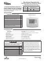
1
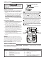
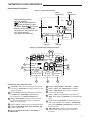
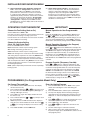
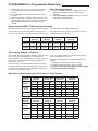
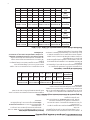
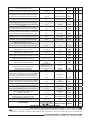
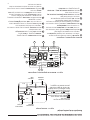
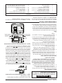
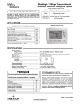
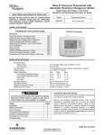
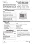
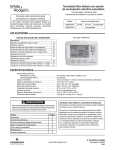
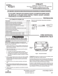
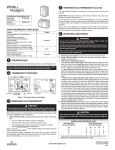
Blue Universal Thermostat with
Automatic Heat/Cool Changeover Option
Single Stage, Multi-Stage or Heat Pump
Installation and Operating Instructions for Model:
Save these instructions for future use!
Model
FAILURE TO READ AND FOLLOW ALL INSTRUCTIONS
CAREFULLY BEFORE INSTALLING OR OPERATING
THIS CONTROL COULD CAUSE PERSONAL INJURY
AND/OR PROPERTY DAMAGE.
1F85-0422
1F83-0422
Programming Choices
5/1/1 Day
5/2 Day
Non-Programmable
Non-Programmable
APPLICATIONS
THERMOSTAT APPLICATION GUIDE
1F83-0422 Thermostat
Description
Heat Pump (No Aux. or Emergency Heat)
Yes
Heat Pump (with Aux. or Emergency Heat)
Yes
Systems with up to 2 Stages Heat, 2 Stages Cool
Yes
Heat Only Systems (with optional fan switch)
Yes
Millivolt Heat Only Systems – Floor or Wall Furnaces
Yes
Cool Only Systems
Yes
Gas or Oil Heat
Yes
Electric Furnace
Yes
Hydronic (Hot Water) Zone Heat – 2 Wires
Yes
Hydronic (Hot Water) Zone Heat – 3 Wires
Yes
SPECIFICATIONS
Electrical Rating:
Battery Power..................................................... mV to 30 VAC, NEC Class II, 50/60 Hz or DC
Input-Hardwire.................................................... 20 to 30 VAC
Terminal Load............................................................ 1.5 A per terminal, 2.5A maximum all terminals combined
Setpoint Range.......................................................... 45° to 90°F (7° to 32°C)
Differential (Single Stage).......................................... Heat 0.6°F; Cool 1.2°F (adjustable)
Differential (Heat Pump)............................................ Heat 1.2°F; Cool 1.2°F (adjustable)
Operating Ambient..................................................... 32° to +105°F (0° to +41°C)
Operating Humidity.................................................... 90% non-condensing max.
Shipping Temperature Range.................................... -4° to +150°F (-20° to +65°C)
Dimensions Thermostat............................................. 3-7/16”H x 4-7/16”W x 1-1/4”D
! CAUTION
To prevent electrical shock and/or equipment damage,
disconnect electric power to system at main fuse or
circuit breaker box until installation is complete.
Index
Page
Installation
2
Wiring Connections
Thermostat Quick Reference
Installer Configuration Menu
Operating Your Thermostat
Programming
Troubleshooting
2
3
4
6
6
8
ATTENTION: MERCURY NOTICE
This product does not contain mercury. However, this
product may replace a product that contains mercury.
Mercury and products containing mercury must not be
discarded in household trash. Do not touch any spilled
mercury. Wearing non-absorbent gloves, clean up any
spilled mercury and place in a sealed container. For proper
disposal of a product containing mercury or a sealed
container of spilled mercury, place it in a suitable shipping
container. Refer to www.white-rodgers.com for location to
send product containing mercury.
PART NO. 37-6894D
www.white-rodgers.com
Replaces 37-6894C
0948
1
INSTALLATION
!
Figure 1 – Battery door shown open
WARNING
Thermostat installation and all components of the
control system shall conform to Class II circuits per
the NEC code.
“AA” Alkaline Batteries
Remove Old Thermostat
A standard heat/cool thermostat consists of three basic parts:
1) The cover, which may be either a snap-on or hinge type.
2) The base, which is removed by loosening all captive screws.
3) The switching subbase, which is removed by unscrewing
the mounting screws that hold it on the wall or adapter
plate. Before removing wires from old thermostat,
label each wire with the terminal designation from
which it was attached. Disconnect the wires from the
old thermostat one at a time. Do not let wires fall back
into the wall.
Thermostat can be powered by system AC power or Battery.
If
is displayed, the thermostat is battery powered. If
is not displayed, thermostat is system powered with optional
battery back-up. When battery power remaining is approximately half, the
will be displayed. When “Change
”
is displayed, install fresh “AA” alkaline batteries immediately.
For best results, replace all batteries with new premium brand
alkaline batteries such as Duracell® or Energizer®. We recommend replacing batteries every 2 years. If the home is going
to be unoccupied for an extended period (over 3 months) and
is displayed, the batteries should be replaced before
leaving. When less than two months of battery life remain, the
setpoint temperature will offset by 10 degrees (10 degrees
cooler in Heat mode / 10 degrees warmer in Cool mode). If
offset occurs, the normal setpoint can be manually reset with
or
. Another offset will occur within two days if batteries are not replaced.
Installing New Thermostat
1)
2)
3)
4)
5)
6)
7)
Pull the thermostat body off the thermostat base. Forcing
or prying on the thermostat will cause damage to the unit.
Place base over hole in wall and mark mounting hole
locations on wall using base as a template.
Move base out of the way. Drill mounting holes. If you
are using existing mounting holes and the holes drilled
are too large and do not allow you to tighten base snugly, use plastic screw anchors to secure the base.
Fasten base snugly to wall using mounting holes shown
in Figure 2 and two mounting screws. Leveling is for
appearance only and will not affect thermostat operation.
Connect wires to terminal block on base.
Push excess wire into wall and plug hole with a fire resistant material (such as fiberglass insulation) to prevent
drafts from affecting thermostat operation.
Carefully line the thermostat up with the base and snap
into place.
Figure 2 – Thermostat base and rear view of thermostat
Mounting
Hole
Place Level
across
Mounting Tabs
(for appearance only)
Mounting
Hole
Place Level
across
Mounting Tabs
(for appearance only)
Batteries
2 “AA” alkaline batteries are included with the thermostat.
To install the batteries, pull the battery door as shown by the
arrow and lift open. Using the polarity indicated inside the battery door, insert the batteries. To close the battery door, swing
the door down while pulling in the direction of arrow. Once
fully down, snap the door back into position. To replace the
batteries, set system to OFF.
WIRING CONNECTIONS
Refer to 37-6895 for 1F83-0422/1F85-0422 wiring diagram
specifications.
Refer to equipment manufacturers’ instructions for specific
system wiring information. After wiring, see CONFIGURATION
section for proper thermostat configuration.
TERMINAL DESIGNATION DESCRIPTIONS
Terminal
Designation
Description
L...............Heat pump malfunction indicator for systems
with malfunction connection
O...............Changeover valve for heat pump energized
constantly in cooling
B...............Changeover valve for heat pump energized
constantly in heating
Y...............Compressor Relay
Y2..............2nd Stage Compressor
2
Terminal
Designation
Description
W/E.............Heat Relay/Emergency Heat Relay (Stage 1)
W2..............2nd Stage Heat (3rd Stage Heat in HP 2)
G...............Fan Relay
RH..............Power for Heating
RC..............Power for Cooling
C...............Common wire from secondary side of cooling system transformer or heat only system transformer
6...............3 Wire Zone Valve – Energized when no call for Heat
THERMOSTAT QUICK REFERENCE
Home Screen Description
Figure 3 – Home Screen Display
Setting
Temperature
Room
Temperature
Displays the power level of
the 2 “AA” batteries:
indicates good power level
indicates batteries at about
half power. “Change
” indicates
batteries are low and should be
replaced with 2 new premium brand
“AA” Alkaline batteries.
(See page 2 for more details)
Set
FAN
Auto
SYSTEM
Heat
System
Indicator
Menu
Fan
Indicator
Figure 4 – Programming & Configuration Items
2
12
3
1
9
4
Mo Tu We Th Fr Sa Su
P Date Set
Temp Hold
Save
Month Call For Service
Year
Change
Hold
Filter
System On 2
Auto Sched
Cool Savings
Heat Pump
SYSTEM
Heat Emer Auto
Cool Off Time
FAN
On Auto
Run Sched
5
6
8
10
11
Run
Schedule
Menu
7
Programming and Configuration Items
1 “System On” indicates when heating or cooling stage
is energized. “System On +2” indicates when a second
stage is energized.
2 The word HOLD is displayed when the thermostat is in
the HOLD mode. Temp HOLD is displayed when
the thermostat is in a Temporary HOLD mode.
3 Displays Change Filter when the system has run for
the programmed filter time period as a reminder to
change or clean your filter.
4 Displays “Set” for setpoint when in Run Program mode.
5 Displays System Mode (Heat, Emer, Auto, Cool, Off)
or Time in menu mode.
6 Displays Fan Mode (On, Auto) or “Run Sched” in Menu mode.
7 Displays “Run Schedule”, “Schedule”, or “Menu”.
TM
8 Displays “Save” when Cool Savings is working.
Displays “Heat Pump” when system is configured
9
as Heat Pump thermostat.
10 Displays “Hold” in programmable mode when not in
“Hold” mode. Displays Light Bulb in non-programmable
mode.
11 Initially displays “Auto Sched”. If Auto Schedule had
been used or disabled, then it displays “Cool Savings”
when in the Cool Mode if Cool Savings has been enabled in the menu.
12 “Call For Service” indicates a fault in the heating/
cooling system, it does not indicate a fault in the
thermostat.
3
INSTALLER/CONFIGURATION MENU
With thermostat in Heat, Cool or Auto, in normal operation, press the Menu button for at least 5 seconds. The display will show
item #1 in the table below. Press Menu to advance to the next menu, Press
or
to change an item option. Shaded
items are not available to 1F86.
INSTALLER/CONFIGURATION MENU
MENU
DISPLAYED
PRESS
or
to
Press
REF. HP SS BUTTON (FACTORY DEFAULT) select from listed options
1
4
1
1
MENU
(MS 2)
HP 1, SS 1
ELE
1, 2, 4, 5, 6
2
2
2
MENU
3
3
3
MENU
4
4
4
MENU
(GAS) for SS or MS
(ELE) for HP
CS (0)
(Disabled)
E (On)
5
–
5
MENU
CR Heat (ME)
SL, FA
6
5
–
MENU
SL, FA
7
6
6
MENU
CR Heat Pump
(ME)
CR Cool (ME)
or
CR Emer (FA)
OFF
SL, FA
SL
CL (OFF)
Heat Auto
COMMENTS
Selects Multi-Stage (MS 2 No Heat Pump),
Heat Pump 1 (HP 1, 1 compressor),
or Single Stage (SS 1)
GAS setting: furnace controls the blower
ELE setting: thermostat controls the blower
Selects Cool Savings
Value 1 (low) to 6 (high), Value 0 Disables Feature
Selects Energy Management Recovery (EMR)
On or OFF. 1F85 only
Adjustable Anticipation:
Selects heating cycle rate for MS or SS
Adjustable Anticipation (Heat Pump) (only
when heat pump selected in #1)
Adjustable Anticipation:
Selects the cycle rate for cooling (only when
MS 2 or SS 1 is selected in item 1.) or
Selects the cycle rate for Emergency mode
and Auxiliary stage if Heat Pump is selected
in item 1.
Compressor Lockout Time
System Mode Configuration
with Automatic Changeover capability
8
9
7
8
7
8
MENU
MENU
CL On
Heat Cool Off,
Heat Off with Fan icon,
Cool Off
Heat Off without Fan icon
Cool Off, Auto Off
dL (On)
dL OFF
Selects Display Light On or OFF
0
1 HI, 2 HI, 3 HI, 4 HI,
Adjustable Ambient Temperature Display
(current temperature) 1 LO, 2 LO, 3 LO, 4 LO
Selects Fahrenheit/Celsius Temperature Display
°F
°C
L Heat
L 62 to L 89
Selects Limited HEAT Range
(90)
L Cool
L 46 to L 82
Selects Limited COOL Range
(45)
10
11
9
9
10 10
MENU
MENU
12
13
11 11
12 12
MENU
MENU
14
13 13
MENU
15
14 14
MENU
P3
P0, P2
Defaults for 5-1-1 programming (P3) but nonprogrammable (PO) or 5-2 programming (P2)
is available on most models. 1F85 only
16
15 15
MENU
Heat AS (On)
OFF
17
16 16
MENU
Cool AS (On)
OFF
18
17
–
MENU
Heat FA (On)
OFF
19
18
–
MENU
Cool FA (On)
OFF
20
19 17
MENU
dS (On)
OFF
21
20 18
MENU
MENU
Change Filter (OFF)
Change Filter (200 h)
On
25-1975 h
22
21 19
MENU
Cool On (o)
Heat On (b)
22 20
RUN
SCHED
Automatic Schedule for heat mode. 1F85 only.
NA to Cool only system.
Automatic Schedule for cool mode. 1F85 only.
NA to Heat only system.
Fast Heat option may be disabled by
selecting OFF. NA to SS config.
NA to Cool only system.
Fast Cool option may be disabled by
selecting OFF. NA to SS config.
NA to Heat only system.
Selects Automatic daylight Savings Time option
On or OFF. 1F85 only
Selects Filter Change-out Indicator On or OFF.
Change Filter time in 25 hour increments. This
menu only appears if On is selected in above.
Selects operation of the reversing valve terminal
(O/B) output as an O or B terminal.
Returns to Normal Operation
INSTALLER/CONFIGURATION MENU
1)
2)
This control can be configured for:
MS 2 – Multi-Stage System (no heat pump)
HP 1 – Heat Pump with one stage of compressor
SS 1 – Single Stage System
GAS or Electric (ELE) fan operation. If the heating system requires the thermostat to energize the fan, select
ELE. Select GAS if the heating system energizes the fan
on a call for heat.
3) Select Cool Savings™ value – Selects the amount
of adjustment for the Cool Savings™ feature in Cool
mode with 1 (1°) being the least amount of adjustment
and 6 (6°) being the most amount of adjustment. Default
value is 0 which disables this feature. Cool Savings is
an optional energy saving feature that can reduce your
cooling costs. It is based on the principal that lower
indoor humidity makes a slightly higher temperature
feel more comfortable. Cool Savings operates during
periods of high demand which normally occur on the
hottest summer days when a cooling system may run
for hours to reach the thermostat setting. Long cooling
run times also lower the indoor humidity. Cool Savings,
very slowly, adjusts the setpoint temperature to make the
setpoint closer to the displayed room temperature, to a
maximum of the number of degrees you select. Adjusting the setpoint temperature over a long cooling run time
allows the system to reach your set temperature and turn
off. The room temperature will actually be higher than
the thermostat displays but the reduction in humidity will
allow comfort at the slightly higher temperature.
To turn this feature on in the Cool mode press Cool Savings. The display will show “Save” next to the
setpoint temperature. When Cool Savings is making adjustments to the room temperature display “Save” will be
flashing and the displayed room temperature may vary
within the adjustment range you selected.
If “Save” is not displayed and this feature is OFF, no
change will occur when the cooling system is continuously running during periods of high demand.
4) Energy Management Recovery: (this step is skipped if
configured to be non-programmable). Energy Management Recovery (E) On enables the thermostat to start
heating or cooling early to make the building temperature
reach the program setpoint at the time you specify. Heating will start 5 minutes early for every 1° of temperature
required to reach setpoint.
Example: E On is selected and your heating is pro-
grammed to 65° at night and 70° at 7 AM. If the building temperature is 65°, the difference between 65° and
70° is 5°. Allowing 5 minutes per degree, the thermostat
setpoint will change to 70° at 6:35 AM. Cooling allows
more time per degree, because it takes longer to reach
set temperature.
5, 6 & 7) Cycle Rate Selection – The factory default setting
for Heat and Cool modes, SS1 and MS2 is medium cycle
(ME). For Heat Pump and HP1, the default setting is
medium (ME). For Emer (Aux) the default setting is fast
or
cycle (FA). To change cycle rate, press the
key.
Cycle rate differentials for different settings are:
Fast
Medium Slow
MODE FA
ME
SL
Heat (SS1, MS2)
0.4°F 0.6°F 1.7°F
Cool (SS1, MS2)
0.9°F 1.2°F 1.7°F
Heat Pump (HP1)
0.9°F 1.2°F 1.7°F
Emer (HP1)
0.6°F
-
1.7°F
8) Select Compressor Lockout CL OFF or ON – Selecting CL ON will cause the thermostat to wait 5 minutes
between cooling cycles. This is intended to help protect
the compressor from short cycling. Some newer compressors already have a time delay built in and do not
require this feature. Your compressor manufacturer can
tell you if the lockout feature is already present in their
system. When the thermostat compressor time delay occurs, it will flash the setpoint for up to five minutes.
9) System Mode Configuration – This thermostat is configured for Heat and Cool (SYSTEM switch with Cool Off Heat) default. It can also be configured for Heat and Cool with Auto changeover (Heat, Auto, Cool, Off), Heat only
with fan (Off Heat), Heat only without fan, Auto only (Auto Off), and Cool only (Cool Off).
10) Select Backlight Display – The display backlight improves display contrast in low lighting conditions. When
the “C” terminal is powered, selecting backlight CdL ON
will keep the light on continuously. Select backlight OFF
will turn the light on momentarily after any key is pressed.
When the “C” terminal is not powered, the light will be on
momentarily after any key is pressed no matter whether
the backlight is selected ON or OFF.
11) Select Temperature Display Adjustment 4 LO to 4 HI
– Allows you to adjust the room temperature display up
to 4° higher or lower. Your thermostat was accurately calibrated at the factory, but you have the option to change
the display temperature to match your previous thermostat. The current or adjusted room temperature will be
displayed.
12) Select F° or C° Readout – Changes the display readout
to Celsius or Fahrenheit as required.
13) Limited Heat Range – This feature provides a maximum
setpoint temperature for heat. The default setting is 90°F.
It can be changed between 62°F and 89°F by pressing
or
key.
the
14) Limited Cool Range – This feature provide a minimum
setpoint temperature for cool. The default setting is 45°F.
It can be changed between 46°F and 82°F by pressing
or
key.
the
15) Program Options: 1F85 only, configured for 5/1/1 day or
5/2 day programming or non-programming mode. The
default setting is P3, indicating 5/1/1 day programming.
The programs per week can be changed to P2 or P0 by
or
keys. A selection of 0 Days for
pressing the
non-programmable will eliminate the need for EMR, and
that step in the menu will be skipped.
16 & 17)Select Automatic Schedule – 1F85 only, with just one touch of the Auto Schedule key this feature allows
you to program a desired comfort temperature into all the
program periods along with a 6° set back for night periods of both Heat and Cool programs. Factory default is
“On” for both. When Heat AS On and Cool AS On are
activated while in Heat or Cool mode, select desired
setpoint temperature and press Auto Schedule. This
value will be copied into all the morning, day and evening
program periods. The night program periods will have a
6°F set back.
18 & 19)Select Fast Second Stage ON or OFF – Heat
pump or Multi-stage only, in the run mode, with the fast
Heat feature enabled (FA Heat On), if the Heat setpoint
temperature is manually raised by 3°F (2°C) or more
the second
above the actual temperature using
stage will energize immediately. With FA OFF, second
stage will not energize until the setpoint temperature is
1°F or more above actual temperature for more than ten
minutes. The Fast Cool feature (FA Cool) provides the
same controls when the setpoint temperature is lowered.
20) Select Daylight Saving Time Calculation – 1F85 only,
this feature will allow the thermostat to calculate the DST
automatically and apply it to the Real Time Clock display.
or
touch keys to select the
Default On. Use
feature OFF.
5
INSTALLER/CONFIGURATION MENU
21) Select Filter Replacement Reminder and Set Run
Time – Select the “Change Filter” reminder On or
OFF. If selected On, press MENU to select the time
period from 25 to 1975 hours in 25 hours increments.
In a typical system, 200 hours (default) of run time is
approximately 30 days. After the selected time of blower
operation, the thermostat will display “Change Filter”
as a reminder to change or clean your air filter. When
“Change Filter” is displayed, press MENU or RUN
SCHED button to clear the display and restart the time to
the next filter change.
OPERATING YOUR THERMOSTAT
Choose the Fan Setting (Auto or On)
Set the FAN Switch to Auto or On.
Fan Auto is the most commonly selected setting and runs the
fan only when the heating or cooling system is on.
Fan On runs the fan continuously for increased air circulation
or to allow additional air cleaning.
Choose the System Setting
(Heat, Off, Cool, Auto, Emer)
Press the SYSTEM button to select:
Heat: Thermostat controls only the heating system.
Off: Heating and Cooling systems are off.
Cool: Thermostat controls only the cooling system.
Auto: Auto Changeover is used in areas where both heating
and cooling may be required on the same day. AUTO allows
the thermostat to automatically select heating or cooling
depending on the indoor temperature and the selected heat
and cool temperatures. When using AUTO, be sure to set the
Cooling temperatures more than 1° Fahrenheit higher than
the heating temperature.
Emer: (Heat Pump models) Thermostat controls only backup
heating system.
22) Select Reversing Valve Output – The O/B option is
factory set at “O” position. This will accommodate the
majority of heat pump applications, which require the
changeover relay to be energized in COOL. If the
thermostat you are replacing or the heat pump being
installed with this thermostat requires a “B” terminal, to
energize the changeover relay in HEAT, the O/B option
should be set at “B” position.
IMPORTANT!
Manual Operation for Non-Programmable
Mode
Press the SYSTEM button to select Heat or Cool and use
the
or
buttons to adjust the temperature to your
desired setting. After selecting your desired settings you can
also press the SYSTEM button to select AUTO to allow the
thermostat to automatically change between Heat and Cool.
Manual Operation (Bypassing the Program)
Programmable Thermostats
Press
or
and then the HOLD button and adjust the
temperature wherever you like. This will override the program.
The HOLD feature bypasses the program and allows you
to adjust the temperature manually, as needed. Whatever
temperature you set in HOLD will be maintained 24 hours
a day, until you manually change the temperature or press
RUN SCHED to cancel HOLD and resume the programmed
schedule.
Program Override (Temporary Override)
Press
or
buttons to adjust the temperature. This
will override the temperature setting for two hours minimum
or until the next programmed time. To cancel the temporary
setting at any time and return to the program, press Run
Sched. If the SYSTEM button is pressed to select AUTO
the thermostat will change to Heat or Cool, whichever ran
last. If it switches to heat but you want cool, or it changes
to cool but you want heat, press both
and
buttons
simultaneously to change to the other mode.
PROGRAMMING (For Programmable Model Only)
Set Current Time and Date
1) Press MENU and then TIME button once. The display
will show the hour only.
2) Press and hold either the
or
key until you reach
the correct hour and AM/PM designation (AM begins at
midnight, PM begins at noon).
3) Press TIME once again. The display window will show
the minutes only.
4) Press and hold either the
or
key until you reach
the correct minutes.
5) Additional presses of TIME will advance the display to
show the year, month and date of month. Press the
or
key to change the display to the correct setting
for each.
6) Press RUN SCHED to exit the TIME mode.
6
Enter the Heating Program
1) Press SYSTEM button to select “Heat” in the system
switch area indicating the active mode being programmed.
2) Press the MENU button and then press SCHEDULE.
3) The top of the display will show the day(s) being pro
grammed. The time and temperature (flashing) are also
displayed. “1” will also be displayed to indicate the period.
4) Press
or
key to change the temperature to your
selected temperature for the 1st heating period.
5) Press TIME button, time will flash.
6) Press
or
key to adjust the start time for the
1st period.
7) The time will change in 15 minute increments.
8) After you have set the time and the temperature for
the period to begin, press SCHEDULE to advance to the
next program period.
PROGRAMMING (For Programmable Model Only)
9) Repeat steps 2 through 8 until all of the program times
and temperatures are set for all program periods on
that day.
10) Press SCHEDULE to the next day and repeat steps 2
through 9.
11) When programming is complete and all of the times and
temperatures match your desired heating schedule, press
RUN SCHEDULE. The thermostat will now run your
program.
Enter the Cooling Program
1)
2)
Press SYSTEM button to select “Cool” in the system
switch area indicating the active mode being programmed.
Follow Enter Heating Program instructions for entering
cooling times and temperatures.
Energy Saving ENERGY STAR® Factory Pre-Program
The 1F85-0422 thermostats are programmed with the energy
saving settings shown in the table below for all days of the
week. If this program suits your needs, simply set the thermoWake Up
(Period 1)
stat clock and press the RUN SCHED button.
The table below shows the factory set heating and cooling
schedule for all days of the week.
Leave For Work
(Period 2)
Return Home
(Period 3)
Go To Bed
(Period 4)
Heating
Program
6:00 AM
70°F
8:00 AM
62°F
5:00 PM
70°F
10:00 PM
62°F
Cooling
Program
6:00 AM
75°F
8:00 AM
83°F
5:00 PM
75°F
10:00 PM
78°F
Planning Your Program – Important
The Heating and Cooling Program schedules below allow you
to pencil in your own program times and temperatures.
The 1F85-0422 comes configured for 5/1/1 day programming
and can also be configured for 5/2 day programming (see
configuration section).
Factory settings are listed on Monday through Friday, Saturday and Sunday. If you are re-programming a 5/2 day schedule, pencil in your own times and temperatures directly below
the factory times and temperatures.
If you are re-programming a 5+1+1 fill in all lines with the
times and temperatures you want.
Keep the following guidelines in mind when planning your
program.
• In Heating, lower temperatures will save energy.
• In Cooling, higher temperatures will save energy.
• If you plan on using Auto Changeover, do not program the heating higher than the cooling.
Worksheet for Re-Programming 5/2 Day and 5+1+1 Day Program
Heating
Program
Wake Up
(Period 1)
Leave For Work
(Period 2)
Return Home
(Period 3)
Go To Bed
(Period 4)
6:00 AM
70°F
8:00 AM
62°F
5:00 PM
70°F
10:00 PM
62°F
Sat-Sun
or Sat
6:00 AM
70°F
8:00 AM
62°F
5:00 PM
70°F
10:00 PM
62°F
Sun
5+1+1 only
6:00 AM
70°F
8:00 AM
62°F
5:00 PM
70°F
10:00 PM
62°F
Mon-Fri
Cooling
Program
Wake Up
(Period 1)
Leave For Work
(Period 2)
Return Home
(Period 3)
Go To Bed
(Period 4)
6:00 AM
75°F
8:00 AM
83°F
5:00 PM
75°F
10:00 PM
78°F
Sat-Sun
or Sat
6:00 AM
75°F
8:00 AM
83°F
5:00 PM
75°F
10:00 PM
78°F
Sun
5+1+1 only
6:00 AM
75°F
8:00 AM
83°F
5:00 PM
75°F
10:00 PM
78°F
Mon-Fri
7
TROUBLESHOOTING
Reset Operation
Note: When thermostat is reset, installer configuration menu
settings and programming will reset to factory settings.
If a voltage spike or static discharge blanks out the display
or causes erratic thermostat operation, you can reset the
thermostat by removing the wires from terminals R and C
(do not short them together) and removing batteries for 2
minutes. After resetting the thermostat, replace the wires and
batteries. If the thermostat has been reset and still does not
function correctly contact your heating/cooling service person
or place of purchase.
Note: Be sure to review the installer configuration menu
settings.
To reset the programming, clock and configuration settings,
press
and
and the FAN button simultaneously. The
thermostat should go blank and then all segments will be
displayed momentarily.
Symptom
Possible Cause
Correction Action
No Heat/No Cool/No Fan
(common problems)
1.Blown fuse or tripped circuit breaker.
2.Furnace power switch to OFF.
3.Furnace blower compartment door or
panel loose or not properly installed.
4.Loose connection to thermostat or
system.
Replace fuse or reset breaker.
Turn switch to ON.
Replace door panel in proper position to engage safety
interlock or door switch.
Tighten connections.
No Heat
1.Pilot light not lit.
2.Furnace Lock-Out Condition. Heat
may also be intermittent.
Re-light pilot.
Many furnaces have safety devices that shut down when
a lock-out condition occurs. If the heat works intermittently
contact the furnace manufacturer or local HVAC service
person for assistance.
Diagnostic: Set SYSTEM Switch to HEAT and raise the
setpoint above room temperature. Within a few seconds
the thermostat should make a soft click sound. This sound
usually indicates the thermostat is operating properly. If
the thermostat does not click, try the reset operation listed
above. If the thermostat does not click after being reset
contact your heating and cooling service person or place
of purchase for a replacement. If the thermostat clicks,
contact the furnace manufacturer or a HVAC service
person to verify the heating is operating correctly.
3.Heating system requires service or
thermostat requires replacement.
No Cool
1.Cooling system requires service or
thermostat requires replacement.
Same as diagnostic for No Heat condition except set the
thermostat to COOL and lower the setpoint below the room
temperature. There may be up to a five minute delay before
the thermostat clicks in Cooling.
1.Possible short in wiring.
2.Possible short in thermostat.
3.Possible short in heat/cool/fan system.
4.FAN Switch set to Fan ON.
Check each wire connection to verify they are not shorted
or touching together. No bare wire should stick out from
under terminal block. Try resetting the thermostat as
described above. If the condition persists the manufacturer
of your system or service person can instruct you on how
to test the Heat/Cool system for correct operation. If the
system operates correctly, replace the thermostat.
Thermostat Setting &
Thermostat Thermometer
Disagree
1.Thermostat thermometer setting
requires adjustment.
The thermometer can be adjusted +/- 4 degrees. See
Temperature Display Adjustment in the Configuration Menu
section.
Furnace (Air Conditioner)
Cycles Too Fast or Too
Slow (narrow or wide
temperature swing)
1.The location of the thermostat and/or
the size of the Heating System may
be influencing the cycle rate.
Digital thermostats provide precise control and cycle faster
than older mechanical models. The system turns on and off
more frequently but runs for a shorter time so there is no
increase in energy use. If you would like an increased cycle
time, choose SL for slow cycle in the Configuration menu,
step 6 (heat), 7 (cool) or 8 (heat pump). If an acceptable
cycle rate is not achieved, contact a local HVAC service
person for additional suggestions.
Heat, Cool or Fan
Runs Constantly
Homeowner Help Line: 1-800-284-2925
White-Rodgers is a division
of Emerson Electric Co.
The Emerson logo is a
trademark and service mark
of Emerson Electric Co.
8
www.white-rodgers.com
SOLUCIÓN DE PROBLEMAS
Operación de reajuste
Nota: una vez reajustado el termostato, la configuración del menú
instalador/de configuración y la programación volverán a los ajustes
de fábrica.
Si un pico de voltaje o una descarga estática pone en blanco la
pantalla o hace que el termostato funcione de manera errática,
puede reajustar el termostato retirando los cables de las terminales
R y C (no los cortocircuite) y retirando las pilas durante 2 minutos.
Después de reajustar el termostato, vuelva a colocar los cables y
las pilas. Si el termostato se ha reajustado pero aún no funciona
correctamente, póngase en contacto con su servicio técnico de
calefacción/enfriamiento o con el lugar donde realizó la compra.
Nota: asegúrese de revisar los ajustes del menú instalador/
de configuración.
Para reajustar la programación, el reloj y la configuración, presione
y
y el botón FAN simultáneamente. La pantalla del
termostato debería ponerse en blanco y luego, todos los segmentos
se iluminarán durante unos instantes.
1. La luz piloto no está encendida.
2. Condición de bloqueo del calefactor. El
calor también puede ser intermitente.
El sistema no calienta
1. Se quemó el fusible o se disparó el disyuntor.
2. El interruptor de alimentación del calefactor está
en OFF.
3. La puerta o el panel del compartimiento del
soplador del calefactor están sueltos o no están
debidamente instalados.
4. La conexión al termostato o al sistema está suelta.
El sistema no calienta/
El sistema no enfría/
No funciona el ventilador
(problemas comunes)
Causa posible
Síntoma
Acción correctiva
3. El sistema de calefacción requiere servicio
técnico o debe cambiarse el termostato.
El sistema no enfría
Cambie el fusible o vuelva a activar el disyuntor.
Coloque el interruptor en ON.
Vuelva a colocar el panel de la puerta en el lugar correcto para que se
enganche con el interruptor de interbloqueo de seguridad o de la puerta.
Ajuste las conexiones.
Vuelva a encender el piloto.
Muchos calefactores tienen dispositivos de seguridad que se cierran
cuando se produce una condición de bloqueo. Si la calefacción funciona de
manera intermitente, póngase en contacto con el fabricante del calefactor o
con personal técnico local especializado para solicitar ayuda.
Diagnóstico: presione el interruptor SYSTEM para colocarlo en HEAT y
la temperatura de referencia por encima de la temperatura ambiente. En
cuestión de segundos, debería oírse un chasquido suave del termostato.
Por lo general, este sonido indica que el termostato está funcionando
correctamente. Si no se oye un chasquido, intente la operación de
reajuste arriba indicada. Si el termostato no hace un chasquido después
de reajustarlo, póngase en contacto con su personal de servicio técnico
de calefacción y enfriamiento o con el lugar de compra para obtener un
reemplazo. Si el termostato hace un chasquido, póngase en contacto
con el fabricante del calefactor o con personal técnico especializado para
verificar que la calefacción esté funcionando correctamente.
1.La ubicación del termostato y/o el tamaño del
sistema de calefacción pueden influir en la
duración de los ciclos.
Los ciclos del calefactor (aire
acondicionado) son demasiado
cortos o demasiado largos
(oscilación reducida o amplia de la
temperatura)
El termómetro puede ajustarse en +/- 4 grados. Vea Ajuste de pantalla de
temperatura en la sección Menú de configuración.
1.Es necesario ajustar el termómetro del
termostato.
El ajuste del termostato no
coincide con el termómetro
Verifique todas las conexiones de los cables para asegurarse de que no
estén en cortocircuito o tocándose entre sí. No debe sobresalir ningún
cable pelado por debajo del bloque de terminales. Intente reajustar el
termostato como se describe más arriba. Si la condición persiste, el
fabricante de su sistema o el personal técnico podrá indicarle cómo probar
si el sistema de frío/calor está funcionando correctamente. Si el sistema
funciona correctamente, cambie el termostato.
1. Posible cortocircuito en los cables.
2. Posible cortocircuito en el termostato.
3. Posible cortocircuito en el sistema de
calor/frío/ventilador
4. El interruptor FAN está en Fan ON.
El modo de calor, frío o ventilador
funciona de
manera constante
Siga el mismo procedimiento de diagnóstico que cuando el sistema no
calienta pero coloque el termostato en COOL y coloque la temperatura
de referencia por debajo de la temperatura ambiente. El termostato puede
tardar hasta cinco minutos en pasar al modo de enfriamiento.
1.El sistema de enfriamiento requiere servicio
técnico o debe cambiarse el termostato.
Los termostatos digitales proporcionan un control de temperatura preciso y
pueden reiniciar el ciclo más rápidamente que algunos modelos mecánicos
más antiguos. El sistema se enciende y se apaga con más frecuencia pero
funciona durante un período más corto por lo que no hay aumento en el
consumo de energía. Si desea aumentar el tiempo de un ciclo, seleccione
SL para un ciclo lento en el menú de configuración, paso 6 (calor), 7 (frío)
u 8 (bomba de calor). Si no alcanza una velocidad de ciclo aceptable,
póngase en contacto con personal técnico especializado local para obtener
sugerencias adicionales.
LÍNEA DE AYUDA PARA EL USUARIO: 1-800-284-2925
White-Rodgers es una división de
Emerson Electric Co.
El logotipo de Emerson es una
marca comercial y una marca de
servicio de Emerson Electric Co.
8
www.white-rodgers.com
PROGRAMACIÓN (sólo para el modelo programable)
9) Repita los pasos del 2 al 8 hasta que estén ajustadas todas las
horas y temperaturas para todos los períodos de programación
de ese día.
10) Presione Schedule para pasar al día siguiente y repita los
pasos del 2 al 9.
11) Una vez finalizada la programación y cuando todas las horas
y temperaturas coincidan con el programa de calefacción
deseado, presione Run Schedule. A continuación, el termostato ejecutará su programa.
Ingrese el programa de enfriamiento
1) Presione el botón SYSTEM para seleccionar “Cool” en el área
de interruptor del sistema que indica el modo activo que se
está programando.
2) Siga las instrucciones de la sección Ingrese el programa de
calefacción para ingresar las horas y las temperaturas de
enfriamiento.
Pre-programación de fábrica de ahorro de energía ENERGY STAR®
Los termostatos 1F85-0422 están programados con los ajustes de
ahorro de energía indicados en la siguiente tabla para todos los días
de la semana. Si este programa es adecuado para sus necesidades,
simplemente ajuste el reloj del termostato y presione el botón
RUN Sched.
Al despertarse
(Periodo 1)
6:00 AM
Programa de
enfriamiento
6:00 AM
Programa de
calefacción
70°F
75°F
La siguiente tabla muestra la programación de calefacción y enfriamiento ajustada de fábrica para todos los días de la semana.
Al salir al trabajo
(Periodo 2)
8:00 AM
8:00 AM
62°F
83°F
Al volver a casa
(Periodo 3)
5:00 PM
5:00 PM
70°F
75°F
Al irse a dormir
(Periodo 4)
10:00 PM
10:00 PM
62°F
78°F
Planificación del programa – Importante
Los programas de calefacción y enfriamiento que figuran a continuación le permiten ingresar sus propias horas y temperaturas de
programación.
El termostato 1F85-0422 viene configurado para programación de
5/1/1 días y también puede configurarse para programación de 5/2
días (vea la sección Configuración).
Los ajustes de fábrica están indicados de lunes a viernes, sábado
y domingo. Si desea reprogramar con un programa de 5/2 días, ingrese sus propias horas y temperaturas directamente a continuación
debajo de las horas y temperaturas de fábrica.
Si desea reprogramar con un programa de 5+1+1 días, complete
todas las líneas con las horas y temperaturas que desea.
Tenga en cuenta las siguientes indicaciones cuando planifique su
programa.
• En calefacción, las temperaturas más bajas ahorran energía.
• En enfriamiento, las temperaturas más altas ahorran energía.
• Si tiene pensado usar la opción de conmutación automática,
no programe la temperatura de calefacción por encima de la
de enfriamiento.
Planilla de cálculo para la reprogramación a 5/2 días y 5+1+1 días
Programa de
calefacción
Al despertarse
(Periodo 1)
6:00 AM
Lun-Vie
6:00 AM
Dom
Sólo 5+1+1
6:00 AM
Sáb-Dom
o Sáb
Programa de
enfriamiento
70°F
6:00 AM
Sáb-Dom
o Sáb
Al salir al trabajo Al volver a casa
(Periodo 2)
(Periodo 3)
8:00 AM
70°F
8:00 AM
70°F
8:00 AM
Al despertarse
(Periodo 1)
6:00 AM
Lun-Vie
6:00 AM
Dom
Sólo 5+1+1
75°F
62°F
62°F
62°F
5:00 PM
70°F
5:00 PM
70°F
5:00 PM
70°F
Al salir al trabajo Al volver a casa
(Periodo 2)
(Periodo)
8:00 AM
75°F
8:00 AM
75°F
8:00 AM
83°F
83°F
83°F
5:00 PM
75°F
5:00 PM
75°F
5:00 PM
75°F
Al irse a dormir
(Periodo 4)
10:00 PM
10:00 PM
10:00 PM
62°F
62°F
62°F
Al irse a dormir
(Periodo 4)
10:00 PM
10:00 PM
10:00 PM
78°F
78°F
78°F
7
MENÚ INSTALADOR/DE CONFIGURACIÓN
al horario DST automáticamente y aplicarlo al reloj de tiempo
real en pantalla. Opción predeterminada: On (activado). Utilice
o
para selecciona la opción OFF
los botones táctiles
(apagado).
21) Selección de recordatorio de cambio de filtro y ajuste de
tiempo de funcionamiento – Coloque “Change Filter” en
On (activado) u OFF (desactivado). Si selecciona On, presione
MENU para seleccionar la cantidad de tiempo desde 25 hasta
1975 horas en incrementos de 25 horas. En una aplicación típica,
200 horas de tiempo de funcionamiento (valor predeterminado)
equivalen a aproximadamente 30 días. Una vez seleccionado el
tiempo de funcionamiento del soplador, el termostato mostrará
“Change Filter” como recordatorio para cambiar o limpiar su
CÓMO USAR EL TERMOSTATO
Elija la configuración del ventilador (Auto u On)
Coloque el interruptor FAN en Auto (automático) u On (activado).
Fan Auto es la configuración más comúnmente seleccionada y hace
funcionar el ventilador únicamente cuando el sistema de calefacción
o enfriamiento está encendido.
La opción Fan On hace funcionar el ventilador de forma continua
para una mayor circulación de aire o para permitir la limpieza
adicional del aire.
Elija la configuración del sistema
(Heat, Off, Cool, Auto, Emer)
Presione el botón SYSTEM para seleccionar:
Heat: el termostato controla únicamente el sistema de calefacción.
Off: los sistemas de calefacción y enfriamiento están apagados.
Cool: el termostato controla únicamente el sistema de enfriamiento.
Auto: la conmutación automática se utiliza en lugares en los
que puede requerirse tanto calefacción como enfriamiento
durante el mismo día. AUTO permite al termostato seleccionar
automáticamente calefacción o enfriamiento según la temperatura
interior y las temperaturas de calor y frío seleccionadas. Cuando
utilice AUTO, asegúrese de ajustar las temperaturas de enfriamiento
a más de 1° Fahrenheit por encima de la temperatura de calefacción.
Emer: (modelos de bomba de calor) El termostato sólo controla el
sistema de calefacción auxiliar.
filtro de aire. Cuando aparezca “Change Filter”, presione el
botón MENU o RUN SCHED para borrar la pantalla y volver a
iniciar el tiempo hasta el siguiente cambio de filtro.
22) Selección de salida de válvula inversora – La opción O/B
viene ajustada de fábrica en la posición “O”. Esta opción es
compatible con la mayoría de las aplicaciones de bomba de
calor, que requieren que el relé de conmutación se energice
en COOL. Si el termostato que desea cambiar o la bomba de
calor que instalará con este termostato requiere una terminal
“B” para energizar el relé de conmutación en HEAT, la opción
O/B debe colocarse en la posición “B”.
¡IMPORTANTE!
Operación manual para modo no programable
Presione el botón SYSTEM para seleccionar Heat o Cool y utilice
los botones
o
para ajustar la temperatura al valor
deseado. Después de seleccionar los valores deseados también
puede presionar el botón SYSTEM para seleccionar AUTO para
permitir que el termostato cambie automáticamente entre Heat y
Cool.
Operación manual (omisión del programa)
Termostatos programables
Presione
o
y el botón HOLD y ajuste la temperatura
cuando lo desee. De esta manera omitirá la ejecución del programa.
La función HOLD pasará por alto el programa y le permitirá ajustar
la temperatura manualmente, según sea necesario. Cualquiera sea
la temperatura que ajuste en HOLD, ésta se mantendrá 24 horas al
día, hasta que la modifique manualmente o hasta que presione Run
Sched para cancelar HOLD y reanudar la programación.
Omisión del programa (omisión temporal)
Presione los botones
o
para ajustar la temperatura. Esto
omitirá el ajuste de temperatura durante dos horas como mínimo
o hasta la siguiente hora programada. Para cancelar el ajuste
temporal en cualquier momento y volver al programa, presione Run
Sched. Si se presiona el botón SYSTEM para seleccionar AUTO,
el termostato cambiará a Heat o Cool, según cuál fue el último que
se ejecutó. Si cambia a calor pero usted desea frío, o si cambia
a frío pero usted desea calor, presione los botones
y
simultáneamente para pasar al otro modo.
PROGRAMACIÓN (sólo para el modelo programable)
1)
1) Presione Menu y luego el botón Time una sola vez. La
pantalla mostrará la hora únicamente.
2) Presione y mantenga presionado los botones
o
hasta llegar a la hora y la designación (AM/PM) correctas (AM
comienza a la medianoche; PM comienza al mediodía).
3) Presione Time una sola vez. La pantalla mostrará los minutos
únicamente.
4) Presione y mantenga presionado los botones
o
hasta llegar al número de minutos correctos.
5) Al presionar Time nuevamente, la pantalla avanzará y mostrará
el año, el mes y el día del mes. Presione el botón
o
para cambiar la pantalla al valor correcto en cada caso.
6) Presione Run Sched para salir del modo Time.
Ingrese el programa de calefacción
Ajuste la hora y día actuales
2)
3)
4)
5)
6)
7)
8)
6
Presione el botón SYSTEM para seleccionar “Heat” en el área
de interruptor del sistema que indica el modo activo que se
está programando.
Presione el botón MENU y luego Schedule.
La parte superior de la pantalla mostrará los días que se están
programando. También aparecerán la hora y la temperatura (de
forma intermitente) y el número “1” para indicar el período.
Presione el botón
o
para modificar la temperatura
mostrada a la temperatura seleccionada para el primer período
de calefacción.
Presione el botón TIME. Aparecerá la hora de forma intermitente.
Presione el botón
o
para ajustar la hora correspondiente
al primer período.
La hora cambiará en incrementos de 15 minutos.
Después de haber ajustado la hora y la temperatura del primer
período, presione Schedule para avanzar al siguiente
período de programación.
MENÚ INSTALADOR/DE CONFIGURACIÓN
1)Este control puede configurarse para:
MS2 – Sistema multietapa (sin bomba de calor)
HP1 – Bomba de calor con una etapa de compresor
SS1 – Sistema de una sola etapa
2) Funcionamiento del ventilador con gas (GAS) o electricidad (ELE).
Si el sistema de calefacción requiere que el termostato energice
el ventilador, seleccione ELE. Seleccione GAS si el sistema de
calefacción energiza el ventilador en una llamada de calor.
3) Selección del valor de Cool Savings™ – Selecciona la cantidad
de ajuste para la función Cool Savings™ en el modo Cool, donde
1 (1°) es el ajuste mínimo y 6 (6°) el ajuste máximo. La opción
predeterminada de fábrica es 0, que desactiva esta función. Cool
Savings es una función de ahorro de energía opcional que puede
reducir sus costos de enfriamiento. Se basa en el principio de que
una menor humedad interior hace que una temperatura ligeramente mayor pueda percibirse como más confortable. Cool
Savings funciona durante los períodos de alta demanda, que
suelen producirse en los días de verano más calurosos cuando
el sistema de enfriamiento funciona durante horas para alcanzar
el ajuste del termostato. Los tiempos de funcionamiento de
enfriamiento largos también reducen la humedad interior. Cool
Savings ajusta muy lentamente la temperatura de referencia
para que se acerque más a la temperatura ambiente visualizada
en pantalla, hasta el valor máximo de grados seleccionado.
Ajustar la temperatura de referencia durante un tiempo de
funcionamiento de enfriamiento largo permite al sistema
alcanzar la temperatura de ajuste y apagarse. En realidad,
la temperatura ambiente será más alta que la indicada en el
termostato, pero la reducción de la humedad proporcionará
confort a una temperatura ligeramente superior.
Para activar esta función en el modo Cool, presione Cool Savings.
La pantalla mostrará “Save” (ahorro) junto a la temperatura de
referencia. Cuando Cool Savings está haciendo ajustes a la
temperatura ambiental, aparecerá la palabra Save en la pantalla
de forma intermitente y la temperatura ambiente visualizada
podrá variar dentro del rango de ajuste seleccionado.
Si no aparece la palabra “Save” y esta función está en OFF, no se
realizarán cambios cuando el sistema de enfriamiento esté funcionando de forma continua durante períodos de alta demanda.
4) Control de energía (EMR) – (este paso se pasa por alto si se
configura como no programable). Cuando el control de energía
(E) está activado (On), hace que el termostato inicie la calefacción
o el enfriamiento antes de la hora prevista para que la temperatura
del edificio alcance el valor fijado en el programa a la hora indicada.
Para la calefacción, el termostato se pone en marcha 5 minutos
antes de la hora prevista por cada grado de temperatura requerido
para llegar a la temperatura fijada.
Ejemplo: Ha seleccionado E (On) y programado la calefacción
a 65 °F durante la noche y a 70° F a las 7 a.m. Si la temperatura
del edificio es de 65° F, la diferencia entre 65° F y 70° F es
de 5° F. Teniendo en cuenta 5 minutos por cada grado de
aumento, la temperatura de referencia del termostato cambiará
a 70° F a las 6:35 a.m. El enfriamiento espera más tiempo por
grado ya que lleva más tiempo alcanzar la temperatura.
5, 6 y 7) Selección de velocidad de ciclo – El ajuste predeterminado de fábrica para los modos Heat y Cool, SS1, MS2, es ciclo
medio (ME). Para Bomba de calor y HP1 el ajuste predeterminado es ciclo medio (ME). Para Emer (Aux) el ajuste predeterminado es ciclo rápido (FA). Para cambiar la velocidad del ciclo,
o
. Los diferenciales de la velocidad
presione el botón
del ciclo para los diferentes ajustes son:
Rápido Medio Lento
MODO FA
ME
SL
Calor (SS1, MS2)
0.4°F
0.6°F
1.7°F
Frío (SS1, MS2)
0.9°F
1.2°F
1.7°F
Bomba de calor (HP1)
0.9°F
1.2°F
1.7°F
Emer (HP1)
0.6°F
-
1.7°F
8) Selección de bloqueo del compresor (CL) OFF (desactivado)
u ON (activado) – Si se selecciona CL ON, el termostato esperará
5 minutos entre ciclos de enfriamiento para evitar que el compresor
realice ciclos de encendido y apagado cortos. Algunos de los
compresores más nuevos ya tienen incorporada una demora
de tiempo y no requieren que esta función esté activada en el
termostato. Consulte al fabricante de su compresor para saber
si su modelo incluye la función de bloqueo. Cuando se produce
la demora de tiempo del compresor del termostato, la pantalla
mostrará la temperatura de referencia de forma intermitente
durante un máximo de cinco minutos.
9) Configuración del modo del sistema – Este termostato está
configurado para calor y frío (interruptor SYSTEM con Cool Off
Heat) de forma predeterminada. También puede configurarse
para calor y frío con conmutación automática (Heat, Auto, Cool,
Off), sólo calor con ventilador (Off Heat), sólo calor sin ventilador,
sólo automático (Auto Off) y sólo frío (Cool Off).
10) Selección de la luz de fondo de la pantalla – La luz de fondo
mejora el contraste de la pantalla en condiciones de poca luz.
Cuando se activa la terminal “C”, la selección de CdL ON mantendrá la luz encendida de forma continua. Al seleccionar OFF,
la luz se mantendrá momentáneamente encendida después
de presionar cualquier botón. Cuando la terminal “C” no está
activada, la luz se encenderá por unos instantes después de
presionar cualquier botón, independientemente de que la luz
de fondo de la pantalla esté en ON o en OFF.
11) Selección del ajuste de la pantalla de temperatura de 4 LO
(4 más abajo) a 4 HI (4 más arriba) – Le permite ajustar la
visualización de la temperatura ambiente 4° más arriba o más
abajo. El termostato viene calibrado con precisión de fábrica
pero usted tiene la opción de cambiar el valor de temperatura
que aparece en la pantalla para que coincida con el de su
termostato anterior. La temperatura ambiente actual o ajustada
aparecerá en la pantalla.
12) Selección de lectura en °F o °C – Cambia la unidad en que
aparece la temperatura en la pantalla a grados centígrados o
Fahrenheit según su preferencia.
13) Rango de calor limitado – Esta función proporciona una
temperatura de referencia máxima para calor. El ajuste predeterminado es de 90° F. Puede ajustarse entre 62° F y 89° F
o
.
presionando el botón
14) Rango de frío limitado – Esta función proporciona una
temperatura de referencia minima para frío. El ajuste predeterminado es de 45° F. Puede ajustarse entre 46° F y 82° F
o
.
presionando el botón
15) Opciones de programa: (sólo en el modelo 1F85) este control
puede configurarse para los modos de programación de 5/1/1
días, 5/2 días o no programable. El ajuste predeterminado es
P3, correspondiente a la opción de programación de 5/1/1 días.
Los programas por semana pueden cambiarse a P2 o a P0
o
. La elección de 0 días
presionando los botones
para el modo no programable eliminará la necesidad de EMR y
se pasará por alto ese paso en el menú.
16 y 17) Selección de programación automática – (sólo en el
modelo 1F85) con sólo pulsar el botón Auto Schedule una
vez podrá programar la temperatura confortable deseada para
todos los períodos de programación junto con una reducción
de 6° para los períodos nocturnos en los programas de calor
y enfriamiento. La opción predeterminada de fábrica es “On”
(activada) para ambos programas. Si Heat AS On y Cool AS
On están activados en el modo Heat o Cool, seleccione la
temperatura de referencia deseada y presione Auto Schedule.
Este valor se copiará en todos los períodos de programación
para mañana, día y noche. En los períodos de programación
para la noche el valor se reducirá en 6° F.
18 y 19) Selección de segunda etapa rápida ON (activada) u OFF
(desactivada) – (sólo en sistemas de bomba de calor o multietapa)
En el modo RUN, con la función de calor rápido activada (FA
Heat On), si la temperatura de referencia de calor se aumenta
manualmente en 3° F (2° C) o más por encima de la temperatura
la segunda etapa se energizará inmediareal con el botón
tamente. Con FA en OFF, la segunda etapa no se energizará
hasta que la temperatura de referencia esté a 1° F o más por
encima de la temperatura real durante más de diez minutos.
La función de frío rápido (FA Cool) proporciona los mismos
controles cuando la temperatura de referencia disminuye.
20) Selección de ajuste a horario de verano (DST) – (Sólo en
el modelo 1F85) Esta función permite al termostato ajustarse
5
MENÚ INSTALADOR/DE CONFIGURACIÓN
Con el termostato en Heat, Cool o Auto, en operación normal, presione el botón Menu durante 5 segundos como mínimo. La pantalla
mostrará la opción 1 tal como se describe en la siguiente tabla. Presione Menu para pasar a la siguiente opción del menu. Presione
para cambiar la opción. Los elementos sombreados no están disponibles en el modelo 1F86.
o
MENÚ INSTALADOR/DE CONFIGURACIÓN
REF.
MENÚ HP
21
22
20
21
19
20
18
19
17
18
16
17
15
16
14
15
13
14
12
13
11
12
10
11
9
10
7
8
8
9
6
7
5
6
–
5
4
4
3
3
2
2
1
1
SS
1
2
3
4
5
–
6
7
8
PRESIONE PANTALLA (AJUSTE
DE FÁBRICA)
EL BOTÓN
MENU
MENU
MENU
MENU
MENU
MENU
MENU
MENU
MENU
(MS 2)
(GAS) para SS o MS
(ELE) para HP
CS (0)
(desactivado)
E (On)
CR Heat (ME)
9
10
11
12
13
14
15
16
–
–
17
18
19
20
MENU
MENU
MENU
MENU
MENU
MENU
MENU
MENU
MENU
MENU
MENU
MENU
Presione
o
para
seleccionar una de las
opciones indicadas
HP 1, SS 1
ELE
1, 2, 4, 5, 6
OFF
SL, FA
SL, FA
CR Cool (ME)
or
CR Emer (FA)
SL, FA
CR Heat Pump
(ME)
CL (OFF)
Heat Auto
Cool Off
22
dL (On)
0
(temperatura actual)
°F
L Heat
(90)
L Cool
(45)
P3
Heat AS (On)
Cool AS (On)
Heat FA (On)
Cool FA (On)
dS (On)
Change Filter (OFF)
Cool On (o)
MENU
Change Filter (200 h)
MENU
SL
CL On
Heat Cool Off, Heat Off con
icono de ventilador, Heat Off
sin icono de ventilador,
Cool Off, Auto Off
dL OFF
1 HI, 2 HI, 3 HI, 4 HI,
1 LO, 2 LO, 3 LO, 4 LO
°C
L 62 to L 89
L 46 to L 82
P0, P2
OFF
OFF
OFF
OFF
OFF
On
25-1975 h
Heat On (b)
RUN
SCHED
OBSERVACIONES
Selecciona multietapa (MS 2, sin bomba de calor), bomba de calor
1 (HP 1, 1 compresor), o una sola etapa (SS 1).
Opción GAS: el calefactor controla el soplador.
Opción ELE: el termostato controla el soplador.
Selecciona Cool Savings
Valor 1 (mínimo) a 6 (máximo); un valor de
0 desactiva la función.
Selecciona Control de Energía (EMR) On (activado) u OFF
(desactivado). Sólo en el modelo 1F85
Adjustable Anticipation (anticipación ajustable): Selecciona la
velocidad del ciclo de calefacción para MS o SS
Adjustable Anticipation (Heat Pump) (anticipación ajustable bomba de calor) (sólo cuando se ha seleccionado bomba de
calor en la opción Nº 1)
Adjustable Anticipation (anticipación ajustable): Selecciona
la velocidad del ciclo para enfriamiento (sólo cuando se ha
seleccionado MS 2 o SS 1 en la opción 1) o selecciona la
velocidad del ciclo para el modo Emergency y etapa auxiliar si
se ha seleccionado bomba de calor en la opción 1
Selecciona el bloqueo del compresor.
Configuración de modo del sistema
con capacidad de conmutación automática
Selecciona Display Light (luz de fondo)
On (encendida) u Off (apagada)
Temperatura ambiente ajustable en pantalla
Selecciona visualización de temperatura en grados Fahrenheit
o Celsius
Selecciona el rango de calor limitado
Selecciona el rango de frío limitado
Predeterminado para programación 5-1-1 (P3) pero se ofrece
no programable (PO) o programación 5-2 (P2) en la mayoría de
los modelos. Sólo en el modelo 1F85
Programación automática para modo Heat. Sólo en el
modelo 1F85. No aplicable a sistemas de sólo frío.
Programación automática para modo Cool. Sólo en el modelo
1F85. No aplicable a sistemas de sólo frío.
La opción Fast Heat puede desactivarse seleccionando OFF.
No aplicable a configuración SS. No aplicable a sistemas de
sólo calor.
La opción Fast Cool puede desactivarse seleccionando OFF.
No aplicable a configuración SS. No aplicable a sistemas de
sólo calor.
Selecciona la opción Automatic daylight Savings Time (ajuste
automático a horario de verano) en On (activada) u OFF
(desactivada). Sólo en el modelo 1F85
Selecciona Filter Change-out Indicator en On (activado) u OFF
(desactivado).
Ajusta la frecuencia de cambio del filtro en incrementos de
25 horas. Este menú sólo aparece si se ha seleccionado On
(activado) en la opción anterior.
Selecciona el funcionamiento de la salida de la terminal de
válvula inversora (O/B) como terminal O o B.
Vuelve al funcionamiento normal
4
GUÍA DE REFERENCIA RÁPIDA DEL TERMOSTATO
Descripción de la pantalla principal
Figura 3 – Pantalla principal
Temperatura
ambiente
Muestra el nivel de carga de
las 2 pilas "AA":
indica buen nivel de carga.
indica que a las pilas les queda
aproximadamente la mitad de la carga.
“Change
” (Cambiar
) indica
que la carga de las pilas es baja y que
deben cambiarse por 2 pilas alcalinas
“AA” nuevas de alguna marca líder.
(Vea más detalles en la página 2)
SYSTEM
Heat
Indicador
SYSTEM
Temperatura
de ajuste
Set
FAN
Auto
Menu
Indicador
FAN
Figura 4 – Elementos de programación y configuración
2
12
3
1
9
4
Mo Tu We Th Fr Sa Su
P Date Set
Temp Hold
Save
Month Call For Service
Year
Change
Hold
Filter
System On 2
Auto Sched
Cool Savings
Heat Pump
6
5
FAN
On Auto
Run Sched
SYSTEM
Heat Emer Auto
Cool Off Time
8
10
11
Run
Schedule
Menu
7
Elementos de programación y configuración
1 “System On” (sistema encendido) indica que la etapa de
calefacción o enfriamiento está energizada. “System On +2”
indica que está energizada una segunda etapa.
7 Muestra “Run Schedule” (ejecutar programa),
“Schedule” (programa), or “Menu” (menú).
2 Muestra la palabra HOLD (mantener) cuando el termostato está
en el modo HOLD. Muestra Temp HOLD cuando el termostato
se encuentra en el modo HOLD temporal.
3 Muestra Change Filter (cambiar filtro) cuando el sistema se ha
utilizado por la cantidad de tiempo programada en el filtro para
recordarle que debe cambiar o limpiar el filtro.
4 Muestra “Set” (ajustar) para ajustar la temperatura de
referencia en el modo Run Program.
TM
8 Muestra “Save” (ahorro) cuando Cool Savings
está en funcionamiento.
9
Muestra “Heat Pump” (bomba de calor) cuando el sistema está
configurado como termostato de bomba de calor.
10 Muestra “Hold” (mantener) en el modo programable cuando
non está en el modo “Hold”. Muestra Light Bulb (bombilla) en
el modo no programable.
11 Muestra inicialmente “Auto Sched”. (programación automática).
Si se ha utilizado o desactivado Auto Schedule, entonces
mostrará “Cool Savings” (ahorro en enfriamiento) cuando el
sistema está en el Cool Mode si se ha activado la opción Cool
Savings en el menú.
5 Muestra el modo del sistema (Heat, Emer, Cool, Auto, Off)
o la hora en el modo menú.
6 Muestra el modo del ventilador (On, Auto), o “Run Sched”
(ejecutar programa) en el modo menú.
12 El mensaje “Call For Service” (llamar al servicio técnico) indica
una falla en el sistema de calefacción/enfriamiento. No indica
una falla en el termostato.
3
INSTALACIÓN
!
¡ADVERTENCIA!
La instalación del termostato y de todos los componentes
del sistema de control debe ajustarse a las normas del
código NEC para los circuitos Clase II.
Retire el termostato viejo
Un termostato de calor/frío estándar consta de tres partes básicas:
1. La cubierta, que puede ser tipo bisagra o de broche.
2. La base, que se retira aflojando todos los tornillos cautivos.
3. La subbase de conmutación, que se retira desenroscando los
tornillos de montaje que la sujetan a la pared o a la placa
adaptadora. Antes de retirar los cables del termostato viejo,
identifique cada cable con la designación de la terminal de
la que lo desconectó. Desconecte los cables del termostato
viejo de a uno a la vez. No deje que los cables vuelvan a
introducirse en la pared.
Instalación del termostato nuevo
1.
2.
3.
4.
5.
6.
7.
Tire del cuerpo del termostato para separarlo de la base. Si
fuerza o hace palanca sobre el termostato, dañará la unidad.
Coloque la base sobre el orificio de la pared y marque las ubica–
ciones de los orificios de montaje usando la base como plantilla.
Mueva la base a un lado. Perfore los orificios de montaje. Si
utiliza los orificios de montaje existentes y son demasiado
grandes y no le permiten ajustar bien la base, use anclajes
plásticos para fijar la base.
Fije bien la base a la pared utilizando los orificios de montaje
que muestra la figura 2 y dos tornillos de montaje. Debe estar
nivelada por razones estéticas solamente, ya que no afectará
el funcionamiento del termostato.
Conecte los cables al bloque de terminales sobre la base.
Empuje el cable que sobresale hacia el interior de la pared y
tape el orificio con un material ignífugo (como aislamiento de
fibra de vidrio) para evitar que las corrientes de aire afecten el
funcionamiento del termostato.
Alinee con cuidado el termostato con la base y engánchelo en
su lugar.
abajo, vuelva a engancharla en su lugar. Para cambiar las pilas,
coloque el sistema en OFF.
Figura 1 – Puerta del compartimiento de las pilas abierta
2 Pilas alcalinas “AA”
El termostato puede funcionar con la alimentación CA del sistema o con
pilas. Si aparece
, significa que el termostato está funcionando
con pilas. Si no aparece el símbolo
significa que el termostato
está funcionando con la alimentación del sistema y, además, cuenta
con alimentación auxiliar opcional con pilas. Cuando aparezca el
mensaje “Change”
(Cambiar
), instale dos pilas alcalinas
“AA” nuevas inmediatamente. Para obtener resultados óptimos, cambie
todas las pilas por pilas alcalinas nuevas de alguna marca líder como
Duracell® o Energizer®. Recomendamos cambiar las pilas cada 2 años.
Si la vivienda va a estar desocupada durante un tiempo prolongado
(más de 3 meses) y aparece el símbolo
las pilas deben cambiarse
antes de partir. Cuando a las pilas les quedan menos de dos meses
de vida útil, la temperatura de referencia se compensará en 10 grados
(10 grados menos en el modo Heat y 10 grados más en el modo Cool).
Si se produce esta compensación, puede reajustarse la temperatura de
referencia normal con los botones
o
. Si no se cambian
las pilas, tendrá lugar otra compensación dentro de los dos días.
Figura 2 – Base del termostato y vista trasera del termostato
Orificio de
montaje
Colocar nivelado
a través de las
lengüetas de montaje
(sólo por razones estéticas)
Orificio de
montaje
Colocar nivelado
a través de las
lengüetas de montaje
(sólo por razones estéticas)
Pilas
El termostato incluye 2 pilas alcalinas “AA”. Para instalar las pilas,
tire de la puerta del compartimiento de las pilas en la direción que
indica la flecha y levántela para abrirla. Coloque las pilas según la
polaridad indicada en la puerta del compartimiento. Para cerrar la
puerta del compartimiento, dóblela hacia abajo empujando en el
sentido indicado por la flecha. Cuando la puerta haya llegado hasta
CONEXIONES ELÉCTRICAS
Refiérase a las instrucciones del fabricante del equipo para ver
información más específica. Después de conectarlo, vea en la sección
CONFIGURACIÓN cómo configurar correctamente el termostato.
Refiérase a 37-6895 para ver las especificaciones del diagrama de
conexiones de los modelos 1F83-0422/1F85-0422.
DESCRIPCIÓN DE LAS DESIGNACIONES DE LAS TERMINALES
Designación
de la terminal Descripción
Designación
de la terminal
L................. Indicador de desperfecto de bomba de calor para sistemas con conexión de desperfectos
O................. Válvula de conmutación para bomba de calor energizada
de forma constante en enfriamiento
B................. Válvula de conmutación para bomba de calor energizada
de forma constante en calefacción
Y................. Relé del compresor
Y2................ Compresor de 2° etapa
Descripción
W/E............... Relé de calor/Relé de calor de emergencia (etapa 1)
W2............... Calor 2° etapa (calor 3° etapa en HP2)
G................. Relé del ventilador
RH............... Alimentación para calefacción
RC............... Alimentación para enfriamiento
C................. Cable neutro del secundario del transformador del sistema de
enfriamiento o del transformador del sistema de sólo calor
6................. Válvula zonificada de 3 cables – Energizada cuando no hay
llamada de calor
2
¡Conserve estas instrucciones para
consultarlas en cualquier momento!
EL NO LEER Y SEGUIR CON CUIDADO TODAS LAS INSTRUCCIONES
ANTES DE INSTALAR O UTILIZAR ESTE CONTROL PODRÍA
CAUSAR LESIONES PERSONALES Y/O DAÑOS MATERIALES.
Termostato Blue Universal con opción
de conmutación calor/frío automática
Una sola etapa, multietapa o bomba de calor
Instrucciones de instalación y uso para el modelo:
Modelo
1F85-0422
Opciones de programación
5/1/1 días
1F83-0422
5/2 días
No programable
No programable
APLICACIONES
GUÍA DE APLICACIÓN DEL TERMOSTATO
1F83-0422 Termostato
Descripción
Sí
Calefacción zonificada hidrónica (agua caliente) – 3 cables
Sí
Calefacción zonificada hidrónica (agua caliente) – 2 cables
Sí
Calefactor eléctrico
Sí
Sistemas de calefacción de gas o aceite
Sí
Sistemas de sólo frío
Sí
Sistemas de sólo calor milivoltios - Calefactores de piso o pared
Sí
Sistemas de sólo calor (con interruptor de ventilador opcional)
Sí
Sistemas con hasta 2 etapas de calor, 2 etapas de frío
Sí
Bomba de calor (con calor auxiliar o de emergencia)
Sí
Bomba de calor (sin calor auxiliar o de emergencia)
ESPECIFICACIONES
Características eléctricas:
Alimentación con pilas................................................ mV a 30 VCA, NEC Clase II, 50/60 Hz o CC
Entrada-Cableado interno.......................................... 20 a 30 VCA
Carga en terminales........................................................... 1.5 A por terminal, 2.5 A máx. en todas las terminales combinadas
Rango de temperatura de referencia.................................. 45° F a 90° F (7° C a 32° C)
Diferencial (una sola etapa)................................................ Calor 0.6° F; frío 1.2° F (ajustable)
Diferencial (bomba de calor).............................................. Calor 1.2° F; frío 1.2° F (ajustable)
Temperatura ambiente operativa........................................ 32° F a 105° F (0° C a +41° C)
Humedad operativa............................................................ 90 % sin condensación máx.
Rango de temperatura de transporte................................. -4° F a +150° F (-20° C a +65° C)
Dimensiones del termostato............................................... 3-7/16 pulg. Al x 4-7/16 pulg. An x 1-1/4 pulg. P
! ¡PRECAUCIÓN!
Para evitar descargas eléctricas y/o daños al equipo,
desconecte la alimentación eléctrica en la caja de fusibles
o disyuntores principal hasta que haya finalizado la
instalación del sistema.
Índice
Página
2
3
4
6
6
8
Conexiones eléctricas
Guía de referencia rápida del termostato
Menú instalador/de configuración
Cómo usar el termostato
Programación
Solución de problemas
2
Instalación
ATENCIÓN: AVISO SOBRE EL CONTENIDO
DE MERCURIO
Este producto no contiene mercurio. No obstante, puede
reemplazar un producto que sí contiene mercurio.
El mercurio y los productos que contienen mercurio no deben
desecharse con los residuos domésticos. No toque el mercurio
derramado. Usando un par de guantes no absorbentes, recoja
el mercurio derramado y viértalo en un recipiente sellado.
Para desechar de forma adecuada un producto que contiene
mercurio o un recipiente sellado con mercurio derramado,
colóquelo en un contenedor de transporte adecuado. Consulte
en www.white-rodgers.com el lugar al que deben enviarse
los productos que contienen mercurio.
N° DE PIEZA 37-6894D
Reemplaza 37-6894C
www.white-rodgers.com
1
0948