1
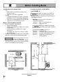
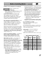
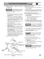
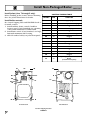
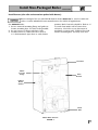
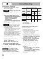
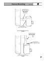
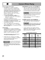
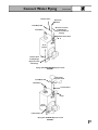
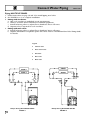
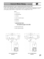
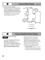
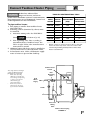
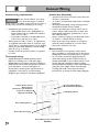
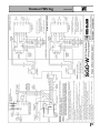
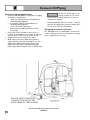
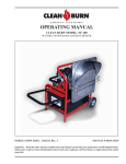
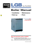
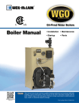
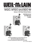
SGO-W SERIES 3 OIL-FIRED NATURAL DRAFT WATER BOILER
This Manual
Includes:
Installation
Start-Up
Boiler Parts
Installer: • Make sure this is the correct manual for the boiler. Verify boiler model on
rating label.
• Leave all documentation received with boiler and burner with unit for
future reference.
User: Boiler and burner must be installed and serviced by qualified service technician.
Part No. 550-141-827/1201
Read This Page First
Hazard Definitions
The following terms are used to bring attention to the presence of hazards of various risk levels or to
important information concerning product life.
Indicates presence of hazards that will cause severe personal injury, death or substantial
property damage if ignored.
Indicates presence of hazards that can cause severe personal injury, death or substantial
property damage if ignored.
Indicates presence of hazards that will or can cause minor personal injury or property
damage if ignored.
Indicates special instructions on installation, operation or maintenance that are important
but not related to personal injury hazards.
Symbol Definitions
The following symbols are used to indicate sequence of installation for:
Factory-assembled block, no burner. Sizes 3 through 6 with jacket installed; water trim controls
shipped separately. Sizes 7 through 9 with jacket and water trim controls shipped separately.
When Calling or Writing About the Boiler
Please have boiler model number and series from boiler rating label and CP number(s) from boiler jacket,
burner and controls. On page 22 of this manual is space to list CP number(s).
2
Table of Contents
Read all instructions before installing. Failure to follow all instructions in proper order
can cause severe personal injury, death or substantial property damage.
Read This Page First . . . . . . . . . . . . . . . . . . . . . . . . . .
Table of Contents . . . . . . . . . . . . . . . . . . . . . . . . . . . .
Before Installing Boiler . . . . . . . . . . . . . . . . . . . . . . .
Install Non-Packaged Boiler . . . . . . . . . . . . . . . . . . . .
Connect Breeching . . . . . . . . . . . . . . . . . . . . . . . . . . .
Connect Water Piping . . . . . . . . . . . . . . . . . . . . . . . .
Connect Tankless Heater Piping . . . . . . . . . . . . . . . .
Connect Wiring . . . . . . . . . . . . . . . . . . . . . . . . . . . . .
Connect Oil Piping . . . . . . . . . . . . . . . . . . . . . . . . . . .
Start-Up . . . . . . . . . . . . . . . . . . . . . . . . . . . . . . . . . . .
Check-Out Procedure . . . . . . . . . . . . . . . . . . . . . . . .
Installation and Service Certificate . . . . . . . . . . . . . .
Appendix . . . . . . . . . . . . . . . . . . . . . . . . . . . . . . . . . .
Parts List . . . . . . . . . . . . . . . . . . . . . . . . . . . . . . . . . .
Parts Drawing . . . . . . . . . . . . . . . . . . . . . . . . . . . . . . .
Dimensions . . . . . . . . . . . . . . . . . . . . . . . . . . . . . . . . .
Ratings . . . . . . . . . . . . . . . . . . . . . . . . . . . . . . . . . . . .
.
.
.
.
.
.
.
.
.
.
.
.
.
.
.
.
.
.
.
.
.
.
.
.
.
.
.
.
.
.
.
.
.
.
.
.
.
.
.
.
.
.
.
.
.
.
.
.
.
.
.
.2
.3
.4-5
.6-9
.10-11
.12-16
.16-17
.18-19
.20
.21
.22
.22
.23
.24
.25
.26-27
.Back Cover
3
Before Installing Boiler
Installations must comply with:
•
U.S.
— State and local plumbing, heating and
electrical codes.
— National codes where applicable.
Canada
— Canadian Standards Association, CSA B139,
Installation Code for Oil-Burning Equipment.
— CSA C22.1 Canadian Electrical Code Part One.
— Applicable local or provincial codes.
•
Provide clearances around boiler
(see FIGURE 1):
Jacket cap must be in place on
boiler to avoid requiring an 18"
minimum clearance from back or top of boiler to
combustible material.
•
Before selecting boiler location:
•
Check for nearby connections to:
— System water piping.
— Chimney. See pages 10-11. Boiler can be top or
back vented.
— Combustion and ventilation air supply.
See page 5.
— Oil supply. See page 20 for oil line routing.
— Electrical power.
Check area around boiler. Remove any combustible
materials, gasoline and other flammable liquids.
•
Minimum clearances from vent pipe to
combustible material:
6 inches — Type “L” doublewall vent*
18 inches — Singlewall vent*
Flue pipe clearances must take
precedence over jacket clearances.
•
Recommended service clearances:
24 inches — Front and top
6 inches — Left side**, back and right side ∆
15 inches — Left side with tankless heater**
12 inches — Right side for burner door
swing radius ∆
Failure to keep boiler area clear
and free of combustible
materials, gasoline and other flammable liquids
and vapors can result in severe personal injury,
death or substantial property damage.
Ceiling
*
6"
(18")
*
6"
(18")
24"
Walls
6" (12") ∆
*
6"
(18")
6"
24"
6" (15")* *
Wall
Floor
Top View
4
Left Side
Recommended Service Clearances
FIGURE 1
Before Installing Boiler
Provide air for combustion and ventilation:
•
Adequate combustion and
ventilation air:
• Assures proper combustion.
• Reduces risk of severe personal injury or death
from possible flue gas leakage and carbon
monoxide emissions.
Do not install exhaust fan in boiler room.
•
Older buildings with single-pane windows,
minimal weather-stripping and no vapor barrier
often provide enough natural infiltration and
ventilation without dedicated openings.
New construction or remodeled buildings are most
often built tighter. Windows and doors are
weather-stripped, vapor barriers are used and
openings in walls are caulked. As a result, such
tight construction is unlikely to allow proper
natural air infiltration and ventilation.
Follow state, provincial or local codes when sizing
adequate combustion and ventilation air openings.
In absence of codes, use the following guidelines
when boiler is in a confined room (defined by NFPA
31 as less than 7200 cubic feet per 1 GPH input of
all appliances in area. A room 8 ft. high x 33.5 ft. x
33.5 ft. is 7200 cu. ft.):
Provide two permanent openings — one within 12
inches of ceiling, one within 12 inches of floor.
Minimum height or length dimension of each
rectangular opening should be at least 3 inches.
When inside air is used — each opening must
freely connect with areas having adequate
infiltration from outside. Each opening should be at
least 140 sq. in. per 1 GPH input (1 sq. in. per 1000
Btu input) of all fuel-burning appliances plus
requirements for any equipment that can pull air
from room (including clothes dryer and fireplace).
When outside air is used — connect each
opening directly or by ducts to the outdoors or to
crawl or attic space that freely connects with
outdoors. Size per below:
• Through outside wall or vertical ducts — at least
35 sq. in. per 1 GPH input (1 sq. in. per 4000 Btu
input) of all fuel-burning appliances plus
requirements for any equipment that can pull
air from room (including clothes dryer
and fireplace).
CONTINUED
Through horizontal ducts — at least 70 sq. in. per
1 GPH boiler input (1 sq. in. per 2000 Btu input)
of all fuel-burning appliances plus requirements for
any equipment that can pull air from room
(including clothes dryer and fireplace).
Where ducts are used, they should have same
cross-sectional area as free area of openings to
which they connect. Compensate for louver,
grille or screen blockage when calculating free
air openings. Refer to their manufacturer’s
instructions for details. If unknown, use:
— Wood louvers, which provide 20-25% free air.
— Metal louvers or grilles, which provide
60-75% free air.
Lock louvers in open position or interlock with
equipment to prove open before boiler operation.
Lay a foundation, if needed:
Boiler may be installed on non-carpeted
combustible flooring.
For residential garage installation, install boiler so
burner is at least 18 inches above floor to avoid
contact with gasoline fumes.
A level concrete or masonry foundation is
required when:
• Floor could possibly become flooded.
• Non-level conditions exist.
Solid concrete blocks can be used to create a pad.
BOILER FOUNDATION SIZE TABLE
BOILER
MODEL
LENGTH
INCHES
WIDTH
INCHES
MIN.
HEIGHT
INCHES
SGO-3W
17
22
2
SGO-4W
20
22
2
SGO-5W
23
22
2
SGO-6W
26
22
2
SGO-7W
29
22
2
SGO-8W
32
22
2
SGO-9W
35
22
2
5
Install Non-Packaged Boiler
Fiberglass wool and ceramic fiber materials:
• POSSIBLE CANCER HAZARD
BY INHALATION
• CAN CAUSE RESPIRATORY,
SKIN AND EYE IRRITATION
This product contains fiberglass wool and ceramic
fiber materials. Airborne fibers from these materials
have been listed by the State of California as a
possible cause of cancer through inhalation. Apply
special care when handling ceramic fiber (chamber
lining, base insulation) materials. Ceramic fibers can
be converted to chrystobalites, a substance listed as a
probable cause of cancer.
Suppliers of fiberglass wool products recommend
the following precautions be taken when handling
these materials:
Precautionary measures:
• Avoid breathing fiberglass dust and contact
with skin and eyes.
• Use NIOSH approved dust/mist respirator.
• Wear long-sleeved, loose fitting clothing, gloves
and eye protection.
• Wash work clothes separately from other
clothing. Rinse washer thoroughly.
• Operations such as sawing, blowing, tearout
and spraying may generate airborne fiber
concentration requiring additional protection.
First aid measures:
• Eye contact — Flush eyes with water to remove
dust. If symptoms persist, seek medical attention.
• Skin contact — Wash affected areas gently
with soap and warm water after handling.
Place boiler:
1. A-SGO-3 through 6W — position on site.
Smaller-sized boilers may be top
heavy. Use caution when
handling to avoid minor personal injury or
property damage.
a. Boiler is shipped for back flue outlet.
To change to top flue outlet (see FIGURE 2):
1) Loosen two screws holding flue cap strap
to collector hood. Remove strap and flue
cap from opening. Re-tighten screws.
2) Check rope placement inside flue cap.
(Read
page 7.)
6
under Step #3 on
3) Loosen two screws on back flue outlet. Set
flue cap on outlet. Install strap by
engaging slots in screws. Tighten screws.
Make sure cap is securely installed.
2. A-SGO-7, 8 & 9W— split the assembled block
for easier handling (see FIGURE 2):
a. Open burner mounting door and,
using utility knife, slit floor insulation at
joint to be separated.
b. Remove 5½" draw rod and the longest draw
rod from each side. Pull block apart. Save
draw rods, nuts, washers and sealing rings
for reassembly.
c. Move divided block to location.
d. Clean port openings with clean rag.
Do not use petroleum-based
compounds to clean
openings. Damage to system components
can result, causing property damage.
e. Place rings in port openings. If ring slips out
of groove, stretch ring gently for several
seconds, then place in groove.
f. Position sections so aligning lugs fit into
sockets of next section. Make sure sealing
rope is in good condition and in position.
g. Oil threads on draw rods. Install washer
and nut on end to be tightened. Use nut
only on other end.
h. With wrench at washer/nut end,
uniformly tighten nuts starting with 5½"
rod at large port, 5½" rod at small port,
bottom long rod and finally top long rod.
i. Torque on both 5½" rods and bottom
long rod should be 50-60 ft. lbs; long
top rod should be 20-25 ft. lbs. Do not
back-off nuts.
j. Metal-to-metal contact should be
made around port openings. If gap
does exist, it should be less than .020".
Check with feeler gauge.
k. If gap around port openings exceeds .020",
check for dirt on port openings, sockets or
misaligned lugs. If corrections are made
and gap still exists, contact your
Weil-McLain distributor or sales office
before continuing installation.
Install Non-Packaged Boiler
3. A-SGO-7, 8 & 9W — install flue collector hood
(see FIGURE 2):
Obtain gas-tight seal to prevent
possible flue gas leakage and
carbon monoxide emissions, leading to severe
personal injury or death.
a. Thread tinnerman clip on screw so that clip
fits snugly in notch of hold-down lug. Screw
must not turn.
b. Remove paper on sealing rope. Starting at
back section near flue collar, position sealing
rope around top of block with adhesive side to
sections. Do not stretch rope. Make sure rope
ends meet. Trim excess rope.
c. Position flue collector hood on top of boiler
sections and over screws and clips as
shown in FIGURE 2.
d. Install washers and nuts. Tighten nuts
until collector hood makes contact with
tinnerman clip.
e. Back flue outlet boiler — Position flue cap and
strap over opening in flue collector hood.
Make sure rope in cap is in place and in
good condition. Tighten strap to hood with
screws provided.
Top flue outlet boiler — Position flue cap
and strap over opening in back section. Make
sure rope in cap is in place and in good
condition. Tighten strap to boiler with screws
provided in section. Install remaining screws
in holes in flue collector hood.
4. Check level. Shim legs, if needed.
Nut
Washer
Sealing Rope in
Groove Inside Cap
Flue Collector
Hood
Tankless heater, if used:
1. SGO-3 through 6W — remove knockout in left
side jacket panel.
2. Remove tankless heater cover plate and gasket.
3. Install new gasket and tankless heater over
studs around opening. Secure with 3/8" nuts.
Perform hydrostatic pressure test:
1. See FIGURE 3 and Control Tapping Table on
page 8 to install:
a. Boiler drain.
b. Water pressure gauge (test only). Be sure
gauge can handle test pressure.
c. Air vent in upper tapping.
d. Plugs in remaining tappings.
2. Fill boiler. Vent all air. Pressure test boiler at
11¼2 times working pressure. For boilers split
and reassembled, test between 75 and 85 psig.
Do not leave boiler unattended.
Cold water fill could expand and
damage cast iron, resulting in severe personal
injury, death or substantial property damage.
3. Check for maintained gauge pressure for more
than 10 minutes. Visually check for leaks if
gauge pressure drops.
4. Drain boiler. Repair leaks if found.
Do not use petroleum-based
compounds to repair leaks.
Damage to system components can result,
causing property damage.
5. Re-test boiler after repairing leaks.
6. Remove pressure gauge, air vent and plugs
from tappings used for controls.
7. Visually check:
a. Sealing rope placement.
b. Metal-to-metal contact around port openings.
c. Flue collector hood seal.
d. Burner mounting door seal.
Sealing Rope with
Adhesive Tape
Flue
Cap
Strap
Flue
Cap
CONTINUED
Obtain gas-tight seal to prevent
possible flue gas leakage and
carbon monoxide emissions, which can lead to
severe personal injury or death.
Tinnerman Clip
Screw
Change from Back Flue Outlet to Top Flue Outlet (Optional)
FIGURE 2
7
Install Non-Packaged Boiler
Install jacket (sizes 7 through 9 only):
Before installing jacket, remove burner mounting
door. See jacket instructions for details.
Install boiler controls:
See Control Tapping Table and FIGURES 3 and 4
to install controls.
1. Install tankless heater control if tankless
heater is used. If not furnished, use operating
control with maximum 10°F differential.
2. Install limit control. If not furnished, use high
limit with maximum 220°F setting.
3. Affix CP number label(s) on jacket front panel.
CONTROL TAPPING TABLE
TAPPING
SIZE
FUNCTION
A1
1½"
Supply Piping
A2
2½"
Air Vent or Expansion Tank Piping
A3
2½"
Plugged
B1
1½"
Return Piping
B2
2"
Plugged
E1
½"
Pressure-Temperature Gauge
E2
½"
Plugged
H
¾"
Drain Valve
L
¾"
High Limit Control
P
¾"
Plugged
R
¾"
Relief Valve
S1 & S2
½"
Plugged
U1
1"
Plugged
U2
¾"
Plugged
¾"
Operating Control for Tankless
Heater
(located in heater plate)
U3
S1
A1
A2
A3
L
E1
E2
P
U3
S2
R
U1
U2
B2
B1
H
Front Section
8
CONTINUED
Back Section
Control Tapping Location
FIGURE 3
Install Non-Packaged Boiler
CONTINUED
Install burner (also refer to instructions packed with burner):
Burners designed for use with Weil-McLain 68 boilers must not be used on GOLD Oil
boilers. Contact individual burner manufacturers for GOLD Oil applications.
For A-SGO-W boiler:
1. Secure universal mounting flange and gasket to
burner mounting door. Use three bolts provided.
2. Secure burner on flange with three bolts.
3. Position burner so end of air tube is level to
1½° tilt downward. Open door to verify burner
position. End of air tube should be flush to ¼"
recessed from inside wall of burner door
refractory. Check for secure placement of
insulation on target wall, chamber floor and
burner mounting door. Securely close door.
Circulator
Water
Pressure
Gauge
Limit
Control
Tankless
Heater
Control
Drain
Valve
Water Boiler Controls
FIGURE 4
9
Connect Breeching
General chimney requirements:
•
Insufficient draft can cause flue
gas leakage and carbon
monoxide emissions, which will lead to severe
personal injury or death.
•
•
Use vent material approved by local codes for
oil-fired burners. In their absence, refer to:
— NFPA 31, Installation of Oil-Burning Equipment.
— NFPA 211, Standard for Chimneys,
Fireplaces, Vents and Solid Fuel
Burning Appliances.
— In Canada, refer to CSA B139, Installation
Code for Oil-Burning Equipment.
NFPA 211 requires chimney to be lined before
connected to boiler.
Inspect existing chimney before
installing new boiler. Failure to
do any of the following will result in severe
personal injury or death:
— Clean chimney, including removal of blockage.
— Repair or replace damaged pipe or liner.
— Repair mortar and joints.
To prevent downdrafts, extend chimney at least
3 feet above highest point where it passes
through roof and 2 feet higher than any portion
of building within 10 feet. Increase chimney
cross-sectional area and height at least 4% per
1,000 feet above sea level.
•
•
MINIMUM CHIMNEY SIZE TABLE
Designed for natural draft firing. Connect
boiler to vertical chimney.
Minimum clearances from vent pipe to
combustible material:
6 inches — Type “L” doublewall vent
18 inches — Singlewall vent
Minimum chimney sizes should be used.
Oversized chimneys, outside
masonry chimneys and/or derated
inputs can result in condensation in chimney.
Connect breeching:
Long horizontal breechings,
excessive number of tees and
elbows or other obstructions restricting
combustion gas flow can result in possibility of
10
BOILER
MODEL
NUMBER
***
MINIMUM
BREECHING
DIAMETER
SGO-3W
5"
SGO-4W
6"
SGO-5W
6"
SGO-6W
SGO-7W
SGO-8W
SGO-9W
7"
7"
MINIMUM
I=B=R
CHIMNEY SIZE
RECT.
8" x 8"
*
8" x 8"
*
8" x 12"
**
ROUND
MINIMUM
CHIMNEY
HEIGHT
6"
15'
7"
15'
7"
20'
*
6¾" x 6¾" inside liner
** 6½" x 10½" inside liner
*** Flue collar on boiler is 7" diameter
condensation, flue gas leakage and carbon
monoxide emissions, which can lead to severe
personal injury or death.
1. Install 2 flue pipe brackets.
2. Connect full-sized breeching when possible.
See Minimum Chimney Size Table.
— Back outlet — see FIGURE 5.
— Top outlet — see FIGURE 6.
3. Connection must be made above bottom of
chimney to avoid blockage. Breeching must not
enter chimney far enough to cause obstruction.
Use thimble or slip joint where breeching enters
chimney to allow removal for cleaning.
4. When burner and boiler are properly installed,
draft overfire will be approximately -0.01"
to -0.02" W.C. Install barometric control in
breeching, per control manufacturer’s
instructions, when excess draft needs to be
relieved or to comply with applicable codes
and regulations. Use draft gauge to adjust
proper opening.
5. An induced draft fan for the chimney may be
necessary if:
— Excessive resistance to flow of combustion
gases can be expected.
— Cross-sectional area of chimney is smaller
than minimum recommended.
— Chimney height is less than recommended.
Seal all vent joints. Interlock burner with
fan operation.
Connect Breeching
CONTINUED
Typical Location for
Barometric Control
(Also see Control
Manufacturer’s
Instructions)
Flue Pipe Bracket
(One on Each Side of Pipe)
Back Outlet Breeching Connection
FIGURE 5
Typical Location for
Barometric Control
(Also see Control
Manufacturer’s
Instructions)
Flue Pipe Bracket
(One on Each Side of Pipe)
Top Outlet Breeching Connection
FIGURE 6
11
Connect Water Piping
General piping information:
•
•
•
•
If installation is to comply with ASME or
Canadian requirements, an additional high
temperature limit is needed. Install control in
supply piping between boiler and isolation valve.
Set control to a minimum of 20°F above set
point of combination control. Maximum
allowable set point is 220°F. Wire control as
shown on wiring diagram.
Use a low water cutoff device when:
— Boiler is installed above radiation level.
— Required by certain state or local codes or
insurance companies.
Use low water cutoff designed for water
installations. Probe-type is recommended. Purchase
and install in tee in supply line above boiler.
Use backflow check valve in cold water supply
as required by local codes.
“A2” or “A3” tapping not recommended for
system supply piping. If “A2” or “A3” tapping
must be used, adequate air elimination method
must be provided.
Install piping:
•
DIAPHRAGM expansion tank (FIGURE 7):
•
Undersized expansion tanks cause
system water to be lost from relief
valve and makeup water added through fill valve.
Eventual section failure can result.
•
•
Ensure expansion tank size will handle boiler
and system water volume and temperature.
Undersized expansion tanks cause
system water to be lost from relief
valve and makeup water added through fill valve.
Eventual section failure can result.
•
See FIGURE 7 or 8 on page 13 and Water
Piping Size Table at right for near-boiler piping
and single-zone piping. See page 14 to complete
multiple-zone piping or page 15 to complete
piping for systems operating below 140°F.
Connect tank from “A2” tapping shown in
FIGURE 8 to expansion tank. Use 1¼2 " N.P.T.
piping. Pitch any horizontal piping up towards
tank 1 inch per 5 feet of piping.
WATER PIPING SIZE TABLE*
Install relief valve vertically in “R” tapping
on back of boiler. See FIGURE 7 or 8 and also
refer to tag attached to relief valve for
manufacturer’s instructions.
Pipe relief valve discharge line
near floor close to floor drain to
eliminate potential of severe burns. Do not
pipe to any area where freezing could occur.
Do not plug, valve or place any obstruction in
discharge line.
*
12
Install automatic air vent in “A2” tapping as
shown in FIGURE 7.
CLOSED expansion tank (FIGURE 8):
For multiple-boiler piping, refer to Weil-McLain’s
“Primary/Secondary Piping Guide."
•
Make sure expansion tank size will handle boiler
and system water volume and temperature. Tank
must be located near boiler before inlet to circulator.
See tank manufacturer’s instructions for details.
BOILER
MODEL
NUMBER
TO
SYSTEM
FROM
SYSTEM
SGO-3W
1¼"
1¼"
SGO-4W
1¼"
1¼"
SGO-5W
1½"
1½"
SGO-6W
1½"
11¼2 "
SGO-7W
1½"
1½"
SGO-8W
2"
2"
SGO-9W
2"
2"
All piping sizes based on 20°F temperature rise through boiler.
Connect Water Piping
Isolation Valve
Cold Water Fill
Relief Valve
CONTINUED
Automatic
Air Vent
Alternate Location
To Diaphragm
Expansion Tank and
Fittings
Isolation Valve
Pump
From
System
Isolation Valve
To Diaphragm
Expansion Tank
and Fittings
Piping with DIAPHRAGM Expansion Tank
FIGURE 7
Cold Water Fill
Relief Valve
Closed Type
Expansion Tank
To
System
Isolation Valve
Pump
From
System
Isolation Valve
Piping with CLOSED Expansion Tank
FIGURE 8
13
Connect Water Piping
CONTINUED
Piping MULTIPLE ZONES:
1. Follow instructions on page 12 and 13 to install piping near boiler.
2. See FIGURE 9 or 10 to complete installation
3. Zoning with circulators:
a. Size each circulator to individual circuit requirements.
b. Remove circulator (when furnished as standard equipment).
c. Install balancing valves to adjust flow to distribute heat to all zones.
d. Separate relay is required for each circulator.
4. Zoning with zone valves:
a. Install balancing valves to adjust flow to distribute heat to all zones.
b. Separate transformer is required to power zone valves. Refer to “Weil-McLain Zone Valve Wiring Guide”
for details.
Legend:
1
Isolation valve
2
Flow control valve
3
Circulator
4
Zone valve
5
Drain valve
ZONE 2
ZONE 2
ZONE 1
ZONE 1
1
2
1
2
1
3
1
1
1
4
5
5
1
5
14
1
5
Multiple Zoning With CIRCULATORS
FIGURE 9
Multiple Zoning With ZONE VALVES
FIGURE 10
Connect Water Piping
CONTINUED
Recommended piping for systems requiring temperatures below 140°F:
In most systems, this type of piping is not required. If system water temperature requirements are less than
140°F, such as radiant panels or converted gravity systems, use piping as shown in FIGURE 11 or 12. If
system piping is plastic without an oxygen barrier, a heat exchanger must be used.
Legend:
1
Isolation valve
2
Flow control valve
3
Circulator
4
System temperature gauge
5
Zone valve
6
Drain valve
7
System temperature valves
Adjust these valves so that:
- the temperature at gauge 8 is at least 140°F
- the temperature at gauge 9 is at least 160°F
8
Blend temperature gauge
9
Boiler temperature gauge
Piping with CIRCULATORS
FIGURE 11
Piping with ZONE VALVES
FIGURE 12
15
Connect Water Piping
CONTINUED
Use with refrigeration systems:
•
•
Install boiler so that chilled medium is piped in
parallel with heating boiler. Use appropriate valves
to prevent chilled medium from entering boiler.
Consult I=B=R Installation and Piping Guides.
If boiler is connected to heating coils located in
air handling units where they can be exposed
to refrigerated air, use flow control valves or
other automatic means to prevent gravity
circulation during cooling cycle.
Supply
Exp. Tank
1
1
Circ.
Chiller
Circ.
Strainer
Exp. Tank
1
2
1
1
Isolation Valve
2
Balancing Valve
Use with Refrigeration System
FIGURE 13
Connect Tankless Heater Piping
Hot Water Can Scald!
•
•
•
Consumer Product Safety Commission and
some states recommend domestic hot water
temperature of 130°F or less.
When installing an automatic mixing valve,
selection and installation must comply with valve
manufacturer’s recommendations and instructions.
Water heated to a temperature suitable for
clothes washing, dish washing and other
sanitizing needs will scald and cause injury.
16
•
Children, elderly, infirm or physically
handicapped persons are more likely to be
injured by hot water. Never leave them
unattended in or near a bathtub, shower or
sink. Never allow small children to use a hot
water faucet or draw their own bath. If anyone
using hot water in the building fits this
description, or if state laws or local codes
require certain water temperatures at hot
water faucets, take special precautions:
— Install automatic mixing valve set according
to those standards.
— Use lowest practical temperature setting.
— Check water temperature immediately after
first heating cycle and after any adjustment.
Connect Tankless Heater Piping
Studies have indicated that
dangerous bacteria can form in
potable water distribution system if certain minimum
water temperatures are not maintained. Contact local
health department for more information.
TANKLESS HEATER RATINGS TABLE
To pipe tankless heater:
1. Size piping no smaller than tankless heater
inlet and outlet.
2. Following controls (furnished by others) must
be installed:
a. Automatic mixing valve. See FIGURE 14.
(Read
at bottom of p. 16)
b. Flow regulating valve. Size according to
intermittent draw of tankless heater. See
Table at right. Follow valve manufacturer’s
instructions to install.
3. Additional anti-scald devices may be installed at
each hot water faucet, bath and shower outlet.
4. In hard water areas, soften cold domestic supply
water to heaters to prevent lime build-up.
These single wall heat exchangers
comply with National Standard
Plumbing Code provided that:
•
Boiler water (including
additives) is practically nontoxic, having a toxicity rating
or class of 1, as listed in
Clinical Toxicology of
Commercial Products.
•
Boiler water pressure is
limited to max. 30 psig by
approved water relief valve.
CONTINUED
*
BOILER
MODEL
NUMBER
HEATER
NUMBER
INTERMITTENT
DRAW RATINGS
(GPM)*
INLET
AND OUTLET
TAPPING SIZES
SGO-3W
35-S-29
3.50
¾"
SGO-4W
35-S-29
3.75
¾"
SGO-5W
35-S-29
4.00
¾"
SGO-6W
35-S-29
4.00
¾"
SGO-7W
35-S-29
4.00
¾"
SGO-8W
35-S-29
4.00
¾"
SGO-9W
35-S-29
4.00
¾"
Gallons of water per minute heated from 40°F to 140°F with
200°F boiler water temperature. Tested in accordance with
I=W=H Testing and Rating Standard for Indirect Tankless Water
Heaters Tested with Boilers.
Tankless Heater
Control
Flow
Regulating
Valve
Cold
Water
Supply
Mixed
12" Min.
Hot
Cold
Automatic
Mixing
Valve
Tankless Heater Piping
FIGURE 14
17
Connect Wiring
General wiring requirements:
Junction box (furnished):
•
Electric shock hazard. Can cause
severe personal injury or death if
power source, including service switch on boiler, is
not disconnected before installing or servicing.
•
•
•
Installations must follow these codes:
— National Electrical Code, ANSI/NFPA 70,
latest edition and any additional national,
state or local codes.
— In Canada, CSA C22.1 Canadian Electrical
Code Part 1 and any local codes.
Wiring must be N.E.C. Class 1. If original wire
as supplied with boiler must be replaced, type
105°C wire or equivalent must be used. Supply
wiring to boiler and additional control wiring
must be 14 ga. or heavier.
Provide electrical ground at boiler as required
by codes.
Thermostat wiring:
•
•
•
•
•
•
•
Burner wiring:
•
•
Install thermostat on inside wall away from
influences of drafts, hot or cold water pipes,
lighting fixtures, television, sun rays or fireplaces.
Follow instructions with thermostat. If it has a
heat anticipator, set heat anticipator in
thermostat to match power requirements of
equipment connected to it. Boiler wiring
diagrams give setting for standard equipment.
Junction box houses electrical connections for
all boiler components.
“A” boilers are furnished with burner and limit
harnesses.
All field-provided high voltage wiring must be
sheathed in flexible metal conduit.
Connect incoming line voltage “HOT” wire to
service switch and neutral wire to white wire.
Field-install equipment ground wire to green
wire with wire nut.
Service switch (15 amp) is provided with boiler.
“A” boilers — install switch as shown.
Some local codes may require an emergency
shut-off switch installed at a location away
from boiler. Follow local codes.
Burner harness incorporates a disconnect
plug, providing a convenient way to disconnect
wiring when burner mounting door is opened.
On “A” boilers, mount the plug (provided in
water trim carton) on the burner housing as
shown in FIGURE 15. For Carlin burners, screw
burner plug into threaded conduit coupling,
then mount this assembly to the burner housing
using the chase nipple. Route wires through
housing and make connections in burner
junction box as shown in boiler wiring diagram.
Circulator Wiring Harness
(Not Furnished on A Boilers)
Tankless Heater Control
Wiring Harness
(Furnished as part of tankless
heater kit as additional
equipment from W-M)
Limit Wiring Harness
Burner Wiring Harness
Burner Disconnect Plug
18
Boiler Wiring for Forced Hot Water
FIGURE 15
Connect Wiring
CONTINUED
19
Connect Oil Piping
General oil piping requirements:
•
•
•
•
Location and installation of oil tanks, oil piping
and burners must follow:
— NFPA 31, Standard for the Installation of
Oil-Burning Equipment.
— In Canada, CSA B139, Installation of
Oil-Burning Equipment.
— Local codes and regulations.
— Information provided with burner and
fuel pump.
If any part of fuel oil tank is above level of
burner, an anti-siphon device must be used to
prevent flow of oil in case of oil line break.
Support oil lines as required by codes.
Make tank connections with swing joints or
copper tubing to prevent breaking in case the
tank settles. Make swing joints so they will
tighten as tank settles. Non-hardening pipe
joint compounds should be used on all threads.
20
Do not use Teflon tape as an
oil pipe sealant. It can cause
valves to fail, creating hazards. Do not use
compression fittings.
•
Underground pipe must be run in a casing to
prevent oil leaking into ground or under floor.
Check local codes for information.
Oil piping connection at burner:
See FIGURE 16 for recommended connection at
burner, allowing burner mounting door to swing
open completely for servicing.
Recommended Oil Piping Connection to Burner
FIGURE 16
Start-Up
Follow information below to prevent
severe personal injury, death or
substantial property damage:
• Do not use gasoline crankcase drainings or
any oil containing gasoline. See burner manual
for proper fuel oil.
• Do not attempt to start burner when excess oil
has accumulated, when unit is full of vapor or
when combustion chamber is very hot.
• Do not start burner unless collector hood, flue
cap, jacket cap, breeching and burner
mounting door are secured in place.
• Never burn garbage or paper in the boiler.
• Never leave combustible material around it.
Fill the system:
1. Close manual and automatic air vents and
boiler drain cock.
2. Fill to correct system pressure. Correct pressure
will vary with each installation. Normal cold
water fill pressure for residential systems is 12
psig. Boiler water pH 7.0 to 8.5 is recommended.
Failure to maintain
recommended pH level can
cause section failure and leaks.
3. Open automatic air vent one turn.
4. Open other vents.
a. Starting on the lowest floor, open air vents
one at a time until water squirts out.
Close vent.
b. Repeat with remaining vents.
5. Refill to correct pressure.
Tips for water systems:
•
Check boiler and system piping for leaks.
Continual makeup water will reduce boiler life.
Minerals can build up in sections, reducing
heat transfer and causing cast iron to
overheat, resulting in section failure.
Failure to maintain recommended
pH and repair leaks can cause
section iron corrosion, leading to section failure
and leaks. Do not use petroleum-based sealing or
stop-leak compounds in boiler systems. Damage
to system components can result.
•
•
When using antifreeze:
Do not use automotive, ethylene
glycol, undiluted or petroleumbased antifreeze. Severe personal injury, death
or substantial property damage can result.
— Use antifreeze especially made for
hydronic systems. Inhibited propylene
glycol is recommended.
— 50% solution provides protection to
about -30°F. Do not exceed 50% mixture.
— Local codes may require back-flow preventer
or actual disconnect from city water supply.
— Determine quantity according to system
water content. Boiler water content is listed
on back cover of manual. Percent of solution
will affect sizing of heat distribution units,
circulator and expansion tank.
— Follow antifreeze manufacturer’s instructions.
To place in operation:
1. Verify boiler is filled with water.
2. Open burner mounting door and verify rear
target wall, floor and burner door insulations
are in proper position.
3. Verify burner mounting door is closed tightly and
burner wiring harness is connected to junction box.
4. Factory burner adjustment and settings may not
be suitable for specific job conditions. For “A”
boilers, see Appendix, page 23.
Make final burner adjustments
using combustion test equipment
to assure proper operation. Do not fire boiler
without water. Sections will overheat, damaging
boiler and resulting in substantial property damage.
5. Vent air from system. Repeat steps 4 and 5
under “Fill the system.” Air in system can
interfere with water circulation and cause
improper heat distribution.
6. Check boiler and system piping for leaks. See
“Tips for water systems.”
7. Inspect breeching and venting for
proper operation.
For pH conditions outside 7.0 to 8.5 range or
unusually hard water areas (above 7 grains
hardness), consult local water treatment company.
For additional information, refer to instructions packed with boiler or burner:
• Burner Manual
• Maintenance and Service Guide for GOLD Oil Water Boilers
21
Check-Out Procedure
Check off steps as completed:
❏
❏
❏
1. Boiler and heat distribution units filled with water?
❏
4. Air purged from oil piping? Piping checked
for leaks?
❏
5. Flue cap in place and tightened? Burner
door closed, sealed and nut tight? Burner
plugged in and service switch on?
2. Automatic air vent, if used, opened one full turn?
3. Air purged from system? Piping checked for leaks
(including tankless heater, if used)?
Obtain gas-tight seal to
prevent possible flue gas
leakage and carbon monoxide emissions,
leading to severe personal injury or death.
❏
6. Proper draft and burner flame? Final adjustment
made with combustion test equipment?
❏
7. Test limit control: While burner is operating,
move indicator on limit control below actual
boiler water temperature. Burner should go
off while circulator continues to operate.
Raise setting on limit control above water
temperature and burner should re-ignite.
❏
8. Test additional field-installed controls: If
boiler has a low water cutoff, additional
high limit or other controls, test for
operation as outlined by manufacturer.
Burner should be operating and should go
off when controls are tested. When controls
are restored, burner should re-ignite.
❏
9. Limit control set to system temperature
requirements (max. 220°F)?
❏ 10.
For multiple zones, flow adjusted to
distribute heat in all zones?
❏ 11.
Thermostat heat anticipator setting
(if available) set properly? Refer to “Connect
wiring,” page 18.
❏ 12.
Boiler cycled with thermostat? Raise to
highest setting and verify boiler goes
through normal start-up cycle. Lower to
lowest setting and verify boiler goes off.
❏ 13.
Observed several operating cycles for
proper operation?
❏ 14.
Set room thermostat(s) to desired
room temperature?
❏ 15.
Completed Installation and Service
Certificate below?
❏ 16.
Reviewed Maintenance and Service
Manual with owner or maintenance
person and instructed person to keep for
future reference?
❏ 17.
Returned all instructions provided with
boiler to its envelope and placed with boiler
for future reference?
Installation and Service Certificate
Date Installed: ______________________________________________
❏
Installation instructions have been followed.
Boiler Model Number: __________________Series: _________
❏
Check-out procedure has been performed.
CP Number(s):______________________________________________
❏
Above information is certified to be correct.
Measured Btu or GPH Input: _____________________________
❏
Information received and left with owner/
maintenance person.
Installer:__________________________________________________________________________________________________________________________
(Company)
(Address)
(Phone)
22
_________________________________________________________________
(Installer’s Signature)
Appendix
Burner adjustments for “A” boilers:
Final burner adjustments must be
made using combustion test
equipment to assure proper operation. Do not fire
boiler without water or sections will overheat.
1. Refer to burner manual for start-up.
2. Allow boiler to heat to design condition.
3. Using combustion test equipment, adjust
burner for:
a. CO2 between 11% and 12% and 0 smoke.
b. -0.01" to -0.02" W.C. draft in
combustion chamber.
To connect SGO-W boilers to Weil-McLain
PLUS indirect-fired water heaters:
Install and wire per water heater manual provided
with water heater.
If boiler already has a tankless heater installed:
• Remove tankless heater and install cover plate
OR
• Leave tankless heater installed. Drain coil and
remove piping. Do not plug holes in tankless
heater front plate.
23
Parts List
Repair parts must be purchased through Weil-McLain for the specific boiler as
indicated in the list below. Results from using modified or other manufactured
parts will not be covered by warranty and may damage boiler or impair operation.
Fig.
No.
A
B
C
D
E
W-M Sales
Part Number
R
Wide Front Section (7011)
Regular Intermediate Section (7015)
Intermediate Section w/Draw Rod Lugs (7016)
Back Section w/7" Flue, Supply & 2" Return (7017)
Section Replacement Kit (For 1 Joint, includes Seals, Rope,Adhesive and
Collector Hood Hardware) Front or Back Section
Section Replacement Kit (For 2 Joints, includes Seals, Rope and Adhesive) Intermediate Section
Section Assembly Complete, For SGO-3W
Section Assembly Complete, For SGO-4W
Section Assembly Complete, For SGO-5W
Section Assembly Complete, For SGO-6W
Section Assembly Complete, For SGO-7W
Section Assembly Complete, For SGO-8W
Section Assembly Complete, For SGO-9W
Collector Hood Kit For SGO-3W*
Collector Hood Kit For SGO-4W*
Collector Hood Kit For SGO-5W*
Collector Hood Kit For SGO-6W*
Collector Hood Kit For SGO-7W*
Collector Hood Kit For SGO-8W*
Collector Hood Kit For SGO-9W*
Tie Rod 1 /2 x 5 1/2 (SGO-7, 8, 9W)
Tie Rod 1 /2 x 103/ 4 (SGO-2 & 7W)
Tie Rod 1 /2 x 121/ 4 (SGO-3W)
Tie Rod 1 /2 x 133/ 8 (SGO-7 & 8W)
Tie Rod 1 /2 x 14 (SGO-8 &9W)
Tie Rod 1 /2 x 15 (SGO-9W)
Tie Rod 1 /2 x 153/ 8 (SGO-4W)
Tie Rod 1 /2 x 161/ 2 (SGO-9W)
Tie Rod 1 /2 x 181/ 2 (SGO-5W)
Tie Rod 1 /2 x 215/ 8 (SGO-6W)
Tie Rod 1 /2 x 243/ 4 (SGO-7W)
Tie Rod 1 /2 x 28 (SGO-8W)
Tie Rod 1 /2 x 31 (SGO-9W)
Heater Cover Plate Carton (Cover Plate, Gasket, Studs & Nuts)
Combustion Chamber Kit (Rear & Frt. Ref., Door Refractory Blanket, Rope, Blanket & Water Glass)
Burner Mounting Door Assembly (Door, Obs. Port, Rope, Ins. & Pins)
Burner Mounting Door (7070)
Door Hinge (7054)
Door Refractory
Door Refractory Blanket
Observation Port Shutter
Door Seal Rope 5'
3
/8" Glass Rope For Collector Hood (7' For Largest Size Hood)
386-700-851
386-700-665
386-700-666
386-700-667
386-700-668
386-700-669
386-700-670
386-700-671
386-700-340
386-700-341
386-700-342
386-700-343
450-020-182
450-020-184
450-020-186
560-234-464
560-234-491
560-234-493
560-234-494
560-234-470
560-234-495
560-234-532
560-234-496
560-234-475
560-234-536
560-234-540
560-234-544
560-234-546
389-900-103
386-700-355
386-700-358
330-054-302
330-054-300
386-700-359
591-222-115
460-039-867
590-735-105
590-735-109
S
Flue Cap Assembly (Cap, Strap, Rope & Screws)
386-700-344
Flue Brush (123D)
591-706-214
F
F
F
F
F
F
F
G
G
G
G
G
G
G
G
G
G
G
G
G
H
J
K
L
M
N
P
Q
*
Description
Includes flue cap assembly, rope and hardware for installation.
24
316-700-245
316-700-065
316-700-070
316-700-265
386-700-852
Parts Drawing
S
D
F
E
R
G
B
A
J
L
J
J
M
J
G
K
G
C
P
N
Q
H
25
Dimensions
20 1/4 [514.4]
7 /4 [196.9]
3
DIMENSIONS - in.
BOILER
MODEL
NUMBER
B
L
SGO-3W
13 1/2
16 7 /8
SGO-4W
16 5/8
20
SGO-5W
19 7/8
231/8
SGO-6W
23
26 1/4
SGO-7W
26 1/8
29 3/8
SGO-8W
29 /4
32 /2
SGO-9W
32 3/8
35 5 /8
Water Supply
Piping
1
101/4
[260.4]
355/8
[904.88]
43/8 DIA [111.1]
Burner Opening
301/16
[763.6]
Return
9 1/2 [241.3]
1
27/16
[61.9]
27/16
[61.9]
1 1/8
[28.6]
SGO-W Front
DIMENSIONS - mm.
7 3/16
[182.6]
BOILER
MODEL
NUMBER
B
L
SGO-3W
342.9
428.7
SGO-4W
422.1
508.0
SGO-5W
504.9
587.2
SGO-6W
584.2
666.7
SGO-7W
663.4
746.2
SGO-8W
742.9
825.5
SGO-9W
822.4
904.7
7 DIA
[177.8]
Heater
Location
B
151/2
[393.7]
L
14 Approx.
SGO-W Side with Burner
26
Dimensions
CONTINUED
Intermediate
7 DIA
[177.8]
61/4
[158.8]
7 DIA
R
[177.8]
299/16
[750.9]
Back
27
Ratings
SGO-W GOLD OIL WATER BOILER RATINGS (1)
I=B=R
BURNER
CAPACITY
GPH (3)
* * -SGO-3W
ROUND
DRAFT
FLUE
BOILER
LOSS
OUTLET
WATER
THRU
ROUND HEIGHT
SIZE
CONTENT BOILER
IN
FT
IN (7)
GAL
IN W.C. (8)
DOE HEATING
CAPACITY (4)
MBH (2)
NET
I=B=R
RATINGS
(5)
DOE
SEASONAL
EFFICIENCY %
AFUE
0.95
115
100
85.3
8x8
6
15
7
14.6
.020
* *-SGO-4W
1.20
145
126
85.0
8x8
6
15
7
16.3
.010
* *-SGO-5W
1.45
175
152
85.0
8x8
7
15
7
18.8
.015
* *-SGO-6W
1.75
212
184
85.0
8x8
7
15
7
21.2
.015
* *-SGO-7W
2.00
242
210
85.0
8x8
8
15
7
23.7
.015
* *-SGO-8W
2.30
266 (6)
231
—
8 x 12
8
20
7
26.2
.025
* *-SGO-9W
2.55
295 (6)
257
—
8 x 12
8
20
7
28.6
.030
BOILER
MODEL
NUMBER
MINIMUM
I=B=R CHIMNEY
RECT
IN
**
Available only as an “A” unit. “A” boiler only for use with approved burners as listed with I=B=R.
(1)
SGO-W boiler designed with convertible vertical and horizontal flue outlet.
(2)
MBH refers to thousands of Btu per hour.
(3)
Based on 140,000 Btu/gal.
(4)
Based on standard test procedures prescribed by the United States Department of Energy at combustion condition of 13.5% CO 2 and -0.02" W.C. draft
overfire.
(5)
Net I=B=R ratings are based on net installed radiation of sufficient quantity for the requirements of the building and nothing need be added for normal
piping and pick-up. Water ratings are based on a piping and pick-up allowance of 1.15. An additional allowance should be made for unusual piping and
pick-up loads. Consult local Weil-McLain Sales Office.
(6)
I=B=R gross output.
(7)
See page 10 for minimum breeching diameter.
(8)
Listed draft losses are for factory-shipped settings.