Download OPERATING MANUAL
Transcript
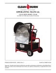
OPERATING MANUAL
CLEAN BURN MODEL: SF-100
SUNFIRE 100 PORTABLE RADIANT HEATER
PUBLICATION DATE: 11/02/15, Rev. 2
MANUAL PART# 43219
Important: Read this entire manual carefully before operating or performing any maintenance on this Radiant Heater.
Misuse may result in serious of fatal injuries due to burns, fire, explosion, electrical shock, or asphyxiation from carbon
monoxide.
TABLE OF CONTENTS
NOTE: A Special Bulletin (which appears just after the Table of Contents) has been added to
your manual to highlight important information about the adjustment and operation of your
Radiant Heater. Be sure to read this sheet before beginning any procedures in this manual.
SECTION 1: INTRODUCTION ........................................................................................................... 1-1
Guide to this Manual & Safety Notifications ................................................................................ 1-1
Specifications and Clearances........................................................................................................ 1-2
Warranty Information .................................................................................................................... 1-3
Special Safety Bulletin .................................................................................................................. 1-4
SECTION 2: OPERATION.................................................................................................................... 2-1
Radiant Heater Operation............................................................................................................... 2-1
Hood Controls Overview ............................................................................................................... 2-2
SECTION 3: MAINTAINING THE RADIANT HEATER ................................................................ 3-1
Removing and Installing Head Assembly ..................................................................................... 3-1
Air Band Adjustment ..................................................................................................................... 3-4
Burner Pressure Adjustment .......................................................................................................... 3-4
Annual Maintenance and Service .................................................................................................. 3-4
Cleaning the Blower ...................................................................................................................... 3-4
Replacing the Blower Motor or Wheel ......................................................................................... 3-4
Motor Maintenance........................................................................................................................ 3-5
Tank Maintenance.......................................................................................................................... 3-5
Ceramic Fiber Removal ................................................................................................................. 3-5
NIOSH First Aid Procedures ......................................................................................................... 3-5
APPENDIX A .......................................................................................................................................... 4-1
Complete Radiant Heater Wiring Diagram................................................................................... A-1
Troubleshooting ............................................................................................................................ A-2
User's Manual: Clean Burn Radiant Heater
SECTION 1: INTRODUCTION
Guide to this Manual
IMPORTANT! This manual provides all the instructions necessary to safely use the Clean Burn
Sunfire Radiant Heater. Please refer to this manual for instructions on operating and maintaining
your Sunfire Radiant Heater.
Consult the Table of Contents for a detailed list of topics covered in this manual. You'll find the step-bystep procedures easy to follow and understand. Should questions arise, please contact your Clean Burn
dealer before starting any of the procedures in this manual.
Please read all sections in this manual carefully--including the following safety information--before
beginning any installation procedures; doing so ensures your safety and the optimal performance of
your Clean Burn Radiant Heater
FOR YOUR SAFETY...
For your safety, Clean Burn documentation may contain
the following types of safety statements (listed here in
order of increasing intensity):
•
NOTE: A clarification of previous
information or additional pertinent information.
•
ATTENTION: A safety statement
indicating that potential equipment damage
may occur if instructions are not followed.
CAUTION: A safety statement
that reminds of safety practices or directs
attention to unsafe practices which could
result in personal injury if proper
precautions are not taken.
WARNING: A strong safety
statement indicating that a hazard exists
which can result in injury or death if proper
precautions are not taken.
DANGER! The utmost levels of
safety must be observed; an extreme hazard
exists which would result in high probability
of death or irreparable serious personal
injury if proper precautions are not taken.
IMPORTANT! Review the list of general safety
precautions provided in your Radiant Heater
Operator's Manual. These precautions must be
heeded to ensure proper, safe operation.
1-1
WARNING!
STOP
YOUR SAFETY IS AT STAKE!
DO NOT INSTALL, OPERATE, OR
MAINTAIN THIS EQUIPMENT
WITHOUT FIRST READING
AND UNDERSTANDING
THIS MANUAL!
User's Manual: Clean Burn Radiant Heater
SPECIFICATIONS & CLEARANCES
Model Sunfire SF-100
Manufacturer
Clean Burn, LLC
Janesville WI
Listed Fuel
NO. 2 Fuel Oil
Input Rating W/No. 2 oil GPH
High1.10
Low 0.97
Minimum Installation Clearance to Combustible Surfaces
Front
72"
Right Side
24"
Left Side
24"
Above
N/A
Back
N/A
Below
0 to Non Combustible Flooring
The designated clearances are the minimum required to avoid overheating; Additional
clearances may be needed for accessibility.
Electrical Rating
120V 2A 60HZ
Fuel Tank Capacity
19.1 US G
Weight
181 LBS Empty
307 LBS Full
Air Setting
1.00 Nozzle
.85 60A
1-2
User's Manual: Clean Burn Radiant Heater
WARRANTY INFORMATION
Clean Burn warrants that it's Radiant Heaters and component parts will be free from defects in material and workmanship
for a period of 24 months from date of purchase when properly installed, operated, and maintained in accordance with
the installation and maintenance instructions, safety guides and labels contained with each unit. If any component proves
defective in either material or workmanship during the limited warranty period, Clean Burn, at its option, may repair the
defective part or equipment or replace the equipment or relevant parts. Proof of purchase and warranty qualification must be
established at time of all returns and exchanges.
BILL OF SALE: A copy of the bill of sale must be provided at time of return.
CLAIM PROCEDURE: All claims are to be submitted to your Clean Burn Distributor.
This limited warranty does not apply to heater, component or replacement part damage resulting from incorrect installation,
misuse, abuse, accident, act of God, neglect, mishandling, contaminated fuel, modification, incorrect environments, or wear
from ordinary use. The warranty set forth above is the exclusive warranty provided by Clean Burn and all other warranties,
including any implied warranties or merchantability or fitness for a particular purpose, are expressly disclaimed. In the
event any implied warranty is not hereby effectively disclaimed due to operation of law, such implied warranty is limited
in duration to the duration of the applicable warranty stated above. The remedies set forth above are the sole and exclusive
remedies available hereunder. Clean Burn will not be liable for any incidental or consequential damages directly or indirectly
related to the sales, handling or use of the equipment, and in any event Clean Burn in connection with the equipment,
including for claims based on negligence or strict liability, is limited to the purchase price. Some states do not allow
limitation on how long an implied warranty lasts, so the above limitation may not apply to you. Some states do not allow the
exclusion or limitation of incidental or consequential damages, so the above limitation or exclusion may not apply to you.
TRADEMARKS
The Clean Burn logo is a trademark of Clean Burn, LLC. All other brand or product names mentioned are the registered
trademarks or trademarks of their respective owners.
COPYRIGHT
Copyright © 2015 Clean Burn, LLC. All rights reserved. No part of this publication may be reproduced, or distributed
without the prior written permission of Clean Burn, LLC. Subject to change without notice.
1-3
User's Manual: Clean Burn Radiant Heater
SPECIAL SAFETY BULLETIN
IMPORTANT INFORMATION CONCERNING SAFETY GUIDELINES
SAFETY GUIDELINES
DANGER:
Carbon monoxide asphyxiation can be fatal.
CARBON MONOXIDE ASPHYXIATION:
The first symptoms of carbon monoxide asphyxiation are similar to that of the flu, headaches, dizziness
and/or nausea. These symptoms could be caused by the malfunction of the Radiant Heater. In this case
go outside immediately. Have the Radiant Heater repaired. Then you may start it again. Some people
are more affected by the effects of carbon monoxide than others, especially pregnant women, those
who suffer from heart or lung disease or people with anemia; also those who have consumed alcoholic
beverages, and those who are at high altitudes. Be sure to read and understand all of the warnings. Save
this manual for future reference: it will provide you with instructions to operate your radiant heater
safely and correctly.
USE ONLY NO. 2 FUEL OIL DIESEL:
To diminish the risk of fire or explosion. Never use gasoline, crankcase drainings, naphtha, paint
thinners, alcohol or other highly flammable materials.
FILLING THE TANK
a. The person filling the tank should be qualified and completely familiar with the factory instructions
for the operation of the radiant heater.
b. Use only the type of fuel expressly specified on the identification plate located on the Radiant Heater.
c. Before filling the tank, extinguish all of the flames, including the radiant heater and wait for the
radiant heater to cool down.
d. While filling the tank inspect all of the fuel lines and their junctions to check for fuel losses. Any
losses must be repaired before starting the radiant heater again.
e. All of the fuel tanks should be located a minimum safety distance from the heater, (like current
government regulation), as well as oxyhydrogen blowpipe/ torches, welding equipment and similar
ignition sources (with the exception of the fuel tank incorporated in the Radiant Heater).
f. The fuel should be stored in areas where the flooring will not soak up any fuel spills or any drips of
fuel line, the flame underneath that could cause a fire.
g. All fuel storage must be stored in compliance with the current regulations.
1-4
User's Manual: Clean Burn Radiant Heater
SAFETY GUIDELINES CONT...
GENERAL OPERATION GUIDELINES
• Never use the Radiant Heater in rooms where aerosol cans, gasoline, and paint thinner, or other
highly flammable materials are located.
• While the heater is in use follow all of the local codes.
• Heaters used close to large pieces of fabric, curtains or other similar materials must be situated at a
safe distance from those objects.
• For the 1st hour of operation run outside due to gases given off by new insulation.
• When moving push, don’t pull.
• Use only well ventilated areas.
• Supply the Radiant Heater with the proper voltage as specified on the identification plate.
• Use only extension cords with three wires correctly connected to a grounded plug.
• The minimum safety distance is the distance required by local code.
• Place the Radiant Heater in a position so that when it is hot or in use it will be on a stable and level
surface, so that you avoid starting a fire.
• When you move or store the Radiant Heater, maintain it in a level position in order to avoid fuel
loss.
• Keep children and animals away from the Radiant Heater.
• Disconnect the Radiant Heater when it is not in use.
• When it is controlled by another device (like a thermostat or a timer), the heater could turn itself on
at any time.
• Never place the Radiant Heater in unoccupied rooms.
• Never use for this radiant heater for a residential application.
• Never block vents.
• When the heater is hot, and connected to the power supply it should never be moved, handled, or
refilled and no maintenance should be performed on it.
• Smoke that is produced from the first combustion is due to the evaporation of organic materials
(ceramic) present in the combustion tank and anti-corrosion oil present on the surface of the burner.
After a few minutes this will stop.
• The operating temperature is -20°F to +80°F
1-5
User's Manual: Clean Burn Radiant Heater
1-6
User's Manual: Clean Burn Radiant Heater
SECTION 2: OPERATION
Following is an outline of the Radiant Heater basic operation process:
RADIANT HEATER OPERATION
Keep unit on a level, non-combustible surface at all times. If the unit is on sitting on a 25° angle or
more the tip switch will prevent the heater from starting.
1. Fill tank with Diesel or #2 Fuel Oil.
2. Plug into a grounded outlet or extension cord.
3. Switch to high fire.
4. Turn power switch ON *.
5. The blower will come on and run for 15 seconds prior to lighting (pre-purge).
6. Once the heater is running you will have a green light for power, and an amber light for high fire.
When the unit is switched to low fire the amber light is off.
7. When shutting down the heater turn power switch to off. Allow the burner to complete the postpurge cycle 300 seconds before disconnecting power. Failure to complete the post purge cycle may
result in excessive heat damaging the unit, as well as a longer pre-purge cycle on the next start.
* : On initial start-up or after running out of fuel it will be necessary to prime the pump. With power
switch off remove black outer burner hood. Loosen the bleeder valve on pump with a 3/8” wrench.
Prepare a small container to catch any oil coming out of the bleeder valve, and then start the unit,
letting the oil run free of any air bubbles. This may require pushing the reset button more than once as
the primary control will shut down if no flame is sensed within 15 seconds. Once the burner priming
process is complete, replace the burner hood.
WARNING: DO NOT OPERATE RADIANT HEATER WITHOUT THE BURNER HOOD
SECURELY ATTACHED.
NOTE: When in operation if the heater runs out of fuel you will have to bleed the pump.
NOTE: After the first hour of operation, the unit will require a re-torque of the screws around the outer
ring on the front of the heater to 23 in/lbs.
2-1
User's Manual: Clean Burn Radiant Heater
HOOD CONTROL DETAIL ZOOM
ON / OFF
INDICATOR
LIGHT
HIGH / LOW
INDICATOR
LIGHT
ON / OFF
TOGGLE
SWITCH
HIGH / LOW
TOGGLE
SWITCH
RESET
SWITCH
TOP OF HOOD
FIGURE 1A: RADIANT HEATER HOOD CONTROLS OVERVIEW
2-2
User's Manual: Clean Burn Radiant Heater
SECTION 3: MAINTENANCE
REMOVING / INSTALLING HEAD ASSEMBLY
WARNING: Only attempt to handle burner components after the unit has fully cooled down.
Components can be hot and could cause severe personal injury.
NOTE: You will need to remove the burner assembly for inspection of the nozzle and electrodes.
To remove the burner assembly:
1. Remove the rear hood screw, and set aside for re-installation.
2. Remove the four bolts securing the burner assembly to the outer cone of the heater.
3. Pull gently to remove the burner assembly from the outer cone of the heater, taking care not to
disconnect any wiring.
4. If nozzles or electrodes are in need of replacement, gently prop the burner assembly on the heater
tank to allow access to nozzle assembly, again taking care not to disconnect any wiring.
To remove the nozzle assembly:
1. Loosen, and then rotate the two screw clamps securing the ignitor plate in place. Swing the ignitor
plate open.
2. Unscrew the oil line fitting and thumb nut at the burner housing. (Figure 2B)
3. Remove the retention head (Figure 2A).
4. Gently push the nozzle assembly through the front of the burner.
5. Handle the nozzle assembly with care to avoid bending/moving the electrodes, or damaging the
electrode ceramic insulators and spinner assembly.
6. Inspect the gasket on the bottom of the ignitor cover. The gasket prevents air from escaping from the
housing. Replace the gasket if not in good condition.
7. Inspect the ignitor contact clips. Clean or replace if necessary to ensure reliable contact with the
electrodes.
FIGURE 2B: OIL LINE FITTING
3-1
User's Manual: Clean Burn Radiant Heater
1/8” to 5/32”
C77015
FLUSH TO 1/16”
SPINNER CLAMP
ELECTRODE
5/16”
OIL TUBE
NOZZLE
ELECTRODE CLAMP
NOZZLE ADAPTER
SPINNER ASSEMBLY
AIR TUBE
RETENTION HEAD
NOZZLE ASSEMBLY
FIGURE 2A: INSERTING / REMOVING NOZZLE HEAD ASSEMBLY
3-2
User's Manual: Clean Burn Radiant Heater
Reinstall nozzle/check electrodes
WARNING: Inspect the nozzle adapter before replacing the nozzle. If the threads have been
damaged or shows score marks, replace the nozzle line/adapter assembly.
Replace the retention head by replacing screw removed during disassembly. When reassembling align
weep hole perpendicular to the bottom of heater, so when unit is fully assembled, weep hole faces the
ground.
When reassembling spinner assembly, the Spinner Clamp should be firmly against the nozzle adapter
shoulder. Tighten Spinner Clamp screw to secure spinner clamp position.
Check the electrode settings. Position the electrodes as shown in Figure 2A. These settings are critical
in ensuring a reliable ignition. Once the electrodes are set, check all clamps to ensure they are securely
tightened.
Figure 3A : CAREFULLY SUPPORT THE NOZZLE ADAPTER
WHEN REMOVING OR INSTALLING NOZZLE
To replace the nozzle assembly, reverse the previous sequence. (See Figure 2A)
Use care when tightening the oil line fitting to oil tube extension. Tighten securely, but do not crossthread or over-tighten.
(SEE FIGURE 2A)
3-3
User's Manual: Clean Burn Radiant Heater
Air Band Adjustment
Air band is pre-set from factory and in most cases will only require adjustment in high altitude locations.
1) To adjust air band, loosen screw and rotate air-band open or closed until desired flame is attained.
2) Re-tighten Screw to re-secure Air Band in newly adjusted position.
Burner Pump Pressure Adjustment
Burner pump pressure is factory set and in most cases should not be changed. If adjustment is required,
please contact your distributor for assistance.
Annual Maintenance and Service Procedures
NOTE: Maintaining and Cleaning your heater at the end of each heating season is important to prolong
the life of your radiant heater and keep it operating in peak condition.
WARNING: Turn off power to appliance when servicing burner. Failure to comply could result
in severe personal injury, death or substantial property damage.
Replace filter element after 200 hours (approximately 5 tanks of fuel).
Clean the blower wheel
The blower wheel accumulates dust and debris from normal operation. You will need to clean the wheel
blades periodically to prevent reduction in airflow.
1. Inspect the blower wheel by removing the blower wheel access cover.
a. To remove the cover, open the ignitor plate and loosen the blower wheel access cover screw
about three turns.
b. Inspect the blower wheel to see if it needs to be cleaned. Dirt and lint on the wheel reduce air
flow, and must be removed if the burner is to operate correctly.
2. To clean blades, remove the two bolts securing the motor to blower housing.
a. Slide the motor out and rotate to remove and access blower wheel.
b. Use a brush and vacuum to clean each blade and the blower housing interior.
3. Replace motor/wheel in blower housing and secure with the two bolts.
4. Push wire slack back into junction box.
Replacing blower motor or wheel
1. If either the blower wheel or motor must be replaced, remove the two bolts securing the motor to
housing.
2. Disconnect the motor wires in the burner junction box.
3. Loosen the Allen screw securing the blower to the motor shaft and remove the wheel.
4. When assembling the replacement assembly, slide the wheel onto the motor shaft and use feeler
gauges to set a space of 3/64 inch between the blower wheel and the motor face.
5. Replace the motor/wheel assembly in the housing, wire the motor leads and secure the motor with
the two bolts.
3-4
User's Manual: Clean Burn Radiant Heater
Motor maintenance
The PSC motor is constructed with permanently-lubricated bearings, and requires no oiling.
CAUTION: Any time you replace a component or disassemble any part of the burner for
service/maintenance, perform a complete operational test after reassembly to verify the burner
operates correctly. Failure to verify operation could result in severe personal injury, death or
substantial property damage
WARNING: CHECKING IGNITOR
Never test an ignitor by placing a screwdriver (or other metallic object) across the high voltage
clips. Check the ignitors only by observing spark at appliance ignition electrodes, with fuel
supply OFF. Using any other method could cause ignitor damage and severe personal injury.
Carefully energize ignitor and check for spark arcing at the high voltage terminals. If spark jumps the
gap, ignitor is good.
Tank maintenance
If it becomes necessary to drain the fuel tank there is a drain plug located on the bottom of the tank.
WARNING: CERAMIC FIBER MATERIALS
The appliance may contain ceramic fiber and/or fiberglass materials. Ceramic fiber materials,
such as chamber liners, may contain carcinogenic particles (chrystobalites) after exposure
to heat. Airborne particles from fiberglass or ceramic fiber components have been listed as
potentially carcinogenic by the State of California. Take the following precautions when
removing, replacing and handling these items.
Avoid breathing dust and avoid contact with skin or eyes. Wear long-sleeved, loose-fitting
clothing, gloves and eye protection.
Use a NIOSH N95 certified respirator. This respirator meets requirements for protection from
chrystobalites. Actual job requirements or NIOSH regulations may require other or additional
protection. For information, refer to the NIOSH website, http://www.cdc.gov/niosh/homepage.html.
Ceramic fiber removal
To prevent airborne dust, thoroughly wet ceramic fiber with water before handling. Place ceramic fiber
materials in a plastic bag and seal to dispose. Avoid blowing, tearing, sawing or spraying fiberglass or
ceramic fiber materials. If such operations are necessary, wear extra protection to prevent breathing
dust. Wash work clothes separately from other laundry. Rinse clothes washer thoroughly afterwards to
prevent contamination of other clothing.
NIOSH First aid procedures:
Eye exposure — irrigate immediately
Breathing — fresh air.
3-5
User's Manual: Clean Burn Radiant Heater
3-6
L1
120
(RED)
L2
A
A
F2
F1
T1 T2
NOT
USED
L1
LIMIT IN
(BLACK)
L2
A-1
FIGURE A1 - COMPLETE WIRING SCHEMATIC
THERMOSTAT
ORANGE
(CABLE TO COVER)
TO ORANGE POWER
BLACK
RED
WHITE
ORANGE
L1
IGNITOR
(BLUE)
L2
WIRING
NUT
T1 T2
L1
VALVE
(VIOLET)
F2
A
GREEN
(CABLE TO COVER)
F1
A
(BLANK)
TO BLOWER MOTOR
PHOTO CELL
RED FROM
ORANGE TERMINAL
L2
WHITE
L1
MOTOR
FAN
(ORANGE)
GREEN
L2
TO SOLENOID
WIRE NUT
IGNITOR
(PN# 33189)
VIOLET
WHITE
SELENOID
WIRE NUT
CONNECTION
PHOTO CELL
BLUE
WIRE NUT
CONNECTION
WHITE
WIRE NUT
CONNECTION
GREEN
RED
BLACK
GREEN
LIGHT
ON
OFF
SWITCH
WHITE
AMBER
LIGHT
HIGH
LOW
SWITCH
WHITE/BLACK
WIRE NUT
CONNECTION
ORANGE
BLOWER
MOTOR
RED
WHITE WIRE (UNDER SHEATH)
WHITE WIRE (UNDER SHEATH)
BLUE
ORANGE
WIRE NUT
CONNECTION
RED/BLACK
(PINK)
COVER SWITCH WIRING
SOLENOID 1
VALVE
VIOLET
WHITE
SOLENOID 2
VALVE
VIOLET
BLACK
WHITE
HEATER, FILTER
BLACK
BLACK
GROUND
SCREW
GREEN
WHITE
WIRE NUT
CONNECTION
WIRE NUT
CONNECTION
RED/BLACK
BLUE
CABLE TO
COVER
CABLE TO
BURNER
WIRE NUT
CONNECTION
BLACK
120 VOLT
3 PRONG
GROUNDED CORD
JUNCTION
BOX
WIRE NUT
CONNECTION
YELLOW
YELLOW
TIP
SWITCH
Technical Reference Materials
OPTIONAL THERMOSTAT CONFIGURATION
OIL
PRIMARY
CONTROL
(PN# 33402)
29456
User's Manual: Clean Burn Radiant Heater
APPENDIX A
User's Manual: Clean Burn Radiant Heater
Troubleshooting
Heater Fails to Start
No Power
No Fuel
Gelled Fuel
Tip Switch
Plugged Nozzle
Electrodes fouled or out of Adjustment
Primary Control Locked Out
Cad Cell Dirty or Defective
Solution
Check Power Cord or Breaker
Check Tank Bleed Pump or look for suction Leak
Warm Fuel add Anti-gell Additive
Move Heater to Level Surface
Replace Nozzle
Clean and Adjust Properly
Hold Reset Button
Clean or Replace
Erratic Flame
Suction Leak
Dirty Nozzle
Fouled Electrodes
Dirty Fuel Filter
Solution
Tighten Suction Lines
Replace Nozzle
Clean
Replace
A-2
NOTES
CLEAN BURN LLC
4109 Capital Circle
Janesville, Wisconsin 53546
1-800-331-0183
www.cleanburn.com
CLEAN BURN is a registered trademark of CLEAN BURN LLC


