1
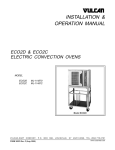
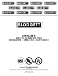
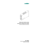
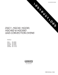
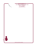
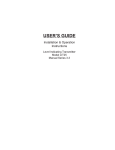
INSTALLATION &
OPERATION MANUAL
ECO SERIES ELECTRIC
CONVECTION OVENS
MODEL
ECO4S
ECO4D
ECO4C
ECO6D
ECO6C
ML-52501
ML-52502
ML-52503
ML-52504
ML-52505
ECO4D
VULCAN-HART
COMPANY,
FORM 30932 Rev. C (2-99)
P.O.
BOX
696,
LOUISVILLE,
KY
40201-0696,
TEL. (502) 7 7 8 - 2 7 9 1
TABLE OF CONTENTS
GENERAL . . . . . . . . . . . . . . . . . . . . . . . . . . . . . . . . . . . . . . . . . . . . . . . . . . . . . . . . . . . . . . . . . . . . . . . . . . . . . 3
INSTALLATION . . . . . . . . . . . . . . . . . . . . . . . . . . . . . . . . . . . . . . . . . . . . . . . . . . . . . . . . . . . . . . . . . . . . . . . . .
Unpacking . . . . . . . . . . . . . . . . . . . . . . . . . . . . . . . . . . . . . . . . . . . . . . . . . . . . . . . . . . . . . . . . . . . . . . .
Location . . . . . . . . . . . . . . . . . . . . . . . . . . . . . . . . . . . . . . . . . . . . . . . . . . . . . . . . . . . . . . . . . . . . . . . . .
Installation Codes and Standards . . . . . . . . . . . . . . . . . . . . . . . . . . . . . . . . . . . . . . . . . . . . . . . . . . . .
Installing Basic Oven . . . . . . . . . . . . . . . . . . . . . . . . . . . . . . . . . . . . . . . . . . . . . . . . . . . . . . . . . . . . . . .
Assembling the Legs to the Oven . . . . . . . . . . . . . . . . . . . . . . . . . . . . . . . . . . . . . . . . . . . . . .
Assembling Cabinet Base or Stand . . . . . . . . . . . . . . . . . . . . . . . . . . . . . . . . . . . . . . . . . . . .
Assembling the Chimney and Flue Extension . . . . . . . . . . . . . . . . . . . . . . . . . . . . . . . . . . . .
Electrical Connections . . . . . . . . . . . . . . . . . . . . . . . . . . . . . . . . . . . . . . . . . . . . . . . . . . . . . . .
Leveling . . . . . . . . . . . . . . . . . . . . . . . . . . . . . . . . . . . . . . . . . . . . . . . . . . . . . . . . . . . . . . . . . .
Casters . . . . . . . . . . . . . . . . . . . . . . . . . . . . . . . . . . . . . . . . . . . . . . . . . . . . . . . . . . . . . . . . . . .
Assembling Stacked Ovens . . . . . . . . . . . . . . . . . . . . . . . . . . . . . . . . . . . . . . . . . . . . . . . . . . . . . . . . .
Electrical Connections . . . . . . . . . . . . . . . . . . . . . . . . . . . . . . . . . . . . . . . . . . . . . . . . . . . . . . .
Leveling . . . . . . . . . . . . . . . . . . . . . . . . . . . . . . . . . . . . . . . . . . . . . . . . . . . . . . . . . . . . . . . . . .
Casters . . . . . . . . . . . . . . . . . . . . . . . . . . . . . . . . . . . . . . . . . . . . . . . . . . . . . . . . . . . . . . . . . . .
4
4
4
4
4
4
4
5
5
5
6
6
7
7
7
OPERATION . . . . . . . . . . . . . . . . . . . . . . . . . . . . . . . . . . . . . . . . . . . . . . . . . . . . . . . . . . . . . . . . . . . . . . . . . . . 8
Controls — Models ECO4S and ECO4D/ECO6D Ovens . . . . . . . . . . . . . . . . . . . . . . . . . . . . . . . . . . 8
Before First Use . . . . . . . . . . . . . . . . . . . . . . . . . . . . . . . . . . . . . . . . . . . . . . . . . . . . . . . . . . . . 9
Using the ECO4S and ECO4D/ECO6D Ovens . . . . . . . . . . . . . . . . . . . . . . . . . . . . . . . . . . . 9
Controls — Model ECO4C/ECO6C Ovens . . . . . . . . . . . . . . . . . . . . . . . . . . . . . . . . . . . . . . . . . . . . 10
Before First Use . . . . . . . . . . . . . . . . . . . . . . . . . . . . . . . . . . . . . . . . . . . . . . . . . . . . . . . . . . . 14
Using the ECO4C/ECO6C Ovens . . . . . . . . . . . . . . . . . . . . . . . . . . . . . . . . . . . . . . . . . . . . . 14
Error Messages — ECO4C/ECO6C Ovens . . . . . . . . . . . . . . . . . . . . . . . . . . . . . . . . . . . . . 15
Roast and Hold Operation . . . . . . . . . . . . . . . . . . . . . . . . . . . . . . . . . . . . . . . . . . . . . . . . . . . . . . . . . 16
Proper Utensils . . . . . . . . . . . . . . . . . . . . . . . . . . . . . . . . . . . . . . . . . . . . . . . . . . . . . . . . . . . . . . . . . . 16
Operating Hints . . . . . . . . . . . . . . . . . . . . . . . . . . . . . . . . . . . . . . . . . . . . . . . . . . . . . . . . . . . . . . . . . . 16
Cooking Guidelines — Models ECO4S and ECO4D/ECO6D Ovens . . . . . . . . . . . . . . . . . . . . . . . . 17
Timer Settings for Rolled Beef Roasts — Model ECO4C/ECO6C Ovens . . . . . . . . . . . . . . . . . . . . 18
Power Outage . . . . . . . . . . . . . . . . . . . . . . . . . . . . . . . . . . . . . . . . . . . . . . . . . . . . . . . . . . . . . . . . . . . 19
Cleaning . . . . . . . . . . . . . . . . . . . . . . . . . . . . . . . . . . . . . . . . . . . . . . . . . . . . . . . . . . . . . . . . . . . . . . . . 19
MAINTENANCE . . . . . . . . . . . . . . . . . . . . . . . . . . . . . . . . . . . . . . . . . . . . . . . . . . . . . . . . . . . . . . . . . . . . . . . . 20
Replacing Lamps . . . . . . . . . . . . . . . . . . . . . . . . . . . . . . . . . . . . . . . . . . . . . . . . . . . . . . . . . . . . . . . . . 20
Service and Parts Information . . . . . . . . . . . . . . . . . . . . . . . . . . . . . . . . . . . . . . . . . . . . . . . . . . . . . . 20
–2–
Installation, Operation And Care Of
ECO SERIES ELECTRIC CONVECTION OVENS
KEEP THESE INSTRUCTIONS FOR FUTURE USE
Your Vulcan Electric Convection Oven is produced with quality workmanship and material. Proper installation,
usage and maintenance of your oven will result in many years of satisfactory performance.
The manufacturer suggests that you thoroughly read this entire manual and carefully follow all of the instructions
provided.
GENERAL
The Model ECO Series Convection Ovens feature a 500°F thermostat, timer, porcelain interior, and a 2-speed,
1
⁄2 H.P. blower motor as standard equipment. Each oven is provided with a standard 208 or 240 volt, 60 Hz, and
1- or 3-phase electrical service. A 480 volt electrical service is available optionally. The oven doors open
independently.
The ECO Series Oven is a single cavity oven. It is furnished with five racks. An open stand with lower storage
rack is available as an option.
Stacked ovens are furnished with a stacking kit for mounting one oven on top of the other.
Features of the models are shown below:
MODEL
OVEN
STYLE
THERMOSTAT
(Each Oven)
TIMER
(Each Oven)
ECO4S
Std. Depth
Mechanical
1-Hour Dial
ECO4D
Std. Depth
Solid State
1-Hour Dial
ECO4C
Std. Depth
Electronic
Electronic
ECO6D
Deep Depth
Solid State
1-Hour Dial
ECO6C
Deep Depth
Electronic
Electronic
Additional racks are available as accessories.
–3–
ROAST &
HOLD
OPTION
GENTLE
BAKE
X
X
X
X
INSTALLATION
UNPACKING
Immediately after unpacking the oven, check for possible shipping damage. If this oven is found to be damaged,
save the packaging material and contact the carrier within 15 days of delivery.
Prior to installation, verify that the electrical service agrees with the specifications on the oven data plate, located
on the inside of the bottom front cover.
Do not use the doors or their handles to lift the oven.
LOCATION
The installation location must allow adequate clearances for servicing and proper operation.
INSTALLATION CODES AND STANDARDS
Vulcan ovens must be installed in accordance with:
In the United States of America:
1. State and local codes.
2. ANSI/NFPA 96, "Vapor Removal from Cooking Equipment" (latest edition), available from National Fire
Protection Association, Batterymarch Park, Quincy, MA 02269.
3. National Electrical Code, ANSI/NFPA-70 (latest edition).
In Canada:
1. Local codes.
2. Canadian Electrical Code CSA Standard C22.2 No. 3 (latest edition), “Electrical Features of Fuel
Burning Equipment.”
INSTALLING BASIC OVEN
The basic oven must be installed on legs or be mounted on a modular stand. Installations on concrete bases
or other supports restricting air circulation underneath the oven is not advisable and may void the warranty. If
using the modular stand, set the oven on the stand after unpacking.
Assembling the Legs to the Oven
1. Unpack the oven and leg set.
2. Position oven on its back, taking care not to scratch or damage it.
3. Attach each of the four leg assemblies to bottom of oven with the 24 bolts and lockwashers (furnished)
(6 per leg). Carefully raise oven to its normal position.
Assembling Cabinet Base or Stand
1. Screw two locating studs (found in cabinet base or stand carton) through the cabinet top flange or the stand
base bottom into bottom of oven (Fig. 1).
2. Attach each of the four leg assemblies to the bottom of the stand with the 24 bolts and lockwashers
(furnished) (6 per leg).
–4–
3. Mount the oven on top of the stand or cabinet (Fig. 1).
Fig. 1
Assembling the Chimney and Flue Extension
Remove the oven chimney and flue extension from the rear of the oven (motor compartment) and use the screws
provided to fasten the chimney to the top rear of the oven. The flanges on the chimney are to be positioned under
the top cover. Also attach the flue extension.
Electrical Connections
WARNING: ELECTRICAL AND GROUNDING CONNECTIONS MUST COMPLY WITH THE APPLICABLE
PORTIONS OF THE NATIONAL ELECTRICAL CODE ANSI/NFPA70 (LATEST EDITION) AND/OR OTHER
LOCAL ELECTRICAL CODES.
WARNING: DISCONNECT ELECTRICAL POWER SUPPLY AND PLACE A TAG AT THE DISCONNECT
SWITCH TO INDICATE THAT YOU ARE WORKING ON THE CIRCUIT.
Remove the wiring compartment cover on the front of the oven. Remove the appropriate knockout on the bottom
of the oven and attach the power supply conduit to the bottom of the oven.
Comply with the appropriate wiring diagram (included with this manual) when making connections to the
electrical supply lines.
Replace the wiring compartment cover and turn on the power supply.
ELECTRICAL DATA
TOTAL
KW
208-240V
480V
3-PHASE LOADING 3-PHASE LOADING
KW PER PHASE
KW PER PHASE
208V
NOMINAL AMPERES PER LINE WIRE
3-PHASE
240V
480V
1-PHASE
208V 240V 480V
Single Oven
Stacked Oven
11
22
L1-L2 L2-L3 L1-L3 L1-L2 L2-L3 L1-L3 L1
L2
L3
L1
L2
L3
L1
L2
L3
3.35 3.35 4.30 3.33 3.33 4.33 32.0 27.9 32.0 27.7 24.2 27.7 13.9 12.0 13.9 52.8 45.8 22.9
6.70 6.70 8.60 6.66 6.66 8.66 64.0 55.8 64.0 55.4 48.4 55.4 27.8 24.0 27.8 105.6 91.6 45.8
The 208, 240, and 480 volt ovens covered by this manual are for connection to a 1- or 3-phase power system. Ovens leaving the factory are
wired for connection to a 3-phase power system. Wires can be changed at the installation site for connection to a 1-phase power system by altering
the wiring at the terminal block.
LEVELING
Adjust the legs to ensure that the oven racks are level in the final installed position.
–5–
CASTERS
If the oven is to be installed on casters, assemble the casters to the legs provided. Place the locking casters on
the front legs and non-locking casters on the rear legs.
ASSEMBLING STACKED OVENS
1. Unpack the ovens and stack kit. Position one oven on its back for access to the oven bottom, taking care
not to scratch or damage it. Attach the four leg assemblies with the 24 bolts and lockwashers (furnished)
(6 per leg).
2. Place lower oven (with legs) on floor and remove two 7⁄16" (11.1 mm) diameter knockouts on each side of
top cover plus the 13⁄8" (35 mm) diameter knockout at the right front of the top cover.
3. Install the two locating studs (included in leg stack set) into screw plates on underside of upper oven (Fig. 2).
4. Remove oven chimneys stored at the rear of both ovens. Discard one chimney. Attach the remaining
chimney to the top of the upper oven (oven without legs) (Fig. 3). The flanges on the chimney are to be
positioned under the top cover.
5. Move the oven with legs to the installed position and place the upper oven on top of the lower oven using
the locating studs. Remove the wiring compartment cover from the front of both ovens. This will facilitate
routing the power leads (furnished) to the top oven, as well as attaching the 1" (25.4 mm) conduit nipple and
locknut (furnished).
6. Attach the short flue extension over the exhaust vent at the rear of the upper oven. Slide the long flue
extension tube over the exhaust vent at the rear of the lower oven (Fig. 3). These extensions should direct
the exhaust fumes upward through and above the top oven.
7. Place the 1" (25.4 mm) conduit nipple through the 13⁄8" (35 mm) hole in the bottom of the top oven and the
top of the bottom oven and clamp the two ovens together with the locknut from the underside.
Fig. 2
Fig. 3
–6–
Electrical Connections
WARNING: ELECTRICAL AND GROUNDING CONNECTIONS MUST COMPLY WITH THE APPLICABLE
PORTIONS OF THE NATIONAL ELECTRICAL CODE AND/OR OTHER LOCAL ELECTRICAL CODES.
WARNING: DISCONNECT ELECTRICAL POWER SUPPLY AND PLACE A TAG AT THE DISCONNECT
SWITCH TO INDICATE THAT YOU ARE WORKING ON THE CIRCUIT.
Ensure that the electrical power supply agrees with the specifications on the oven data plate and complies with
the wiring diagram on the oven.
1. Attach the power leads (furnished as part of the stack set) to the line side of the terminal block of the upper
oven. Then carefully route these leads down through the conduit nipple and behind the control panel of the
lower oven.
2. Attach these leads to the lower oven terminal block per the wiring diagram. At the same time, attach the
power supply conduit to the bottom of the lower oven. Also attach the power supply leads to the line side
of the terminal block.
3. Finally, inspect and check all wiring and terminal connections for tightness and proper routing away from any
moving parts (relay solenoid core), or pinch points (cover on oven frame). Then carefully replace the oven
control panel for both ovens.
Refer to Electrical Data chart on page 5.
LEVELING
Adjust the legs to ensure that the oven racks are level in the final installed position by turning the bottom hex
tips on the floor.
CASTERS
If the stacked ovens are to be installed on casters, assemble the casters to the legs provided. Place the locking
casters on the front legs and non-locking casters on the rear legs.
–7–
OPERATION
CONTROLS — MODELS ECO4S AND ECO4D/ECO6D OVENS (Fig. 3)
;;
;;
;;;;
;;
;
;;
;
;;
;
;
;;
PULL
TO
OPEN
VENT
MAST
ER
SWITC
H
ON LIGHT
OFF
OVEN
COOL
2 SP
EE
MO
D
TOR
ON
OVEN
LAMP
S
HI
ON
OFF
LOW
OFF
OFF
F
50 0
VENT DAMPER CONTROL
HEAT LIGHT
OVEN COOL SWITCH
60
F
OF
AT
LOW
OFF
50 0
OVEN LAMP SWITCH
DISCO
NNEC
CHAN
T SU
GIN
PP
OR AN G FUSE LY BEFO
S, CL
RE
Y OT
EA
HER
SERV NING
ICE
TEMP F
47 5
15 0
45 0
THERMOSTAT
MASTER SWITCH
ON LIGHT
HEAT LIGHT
OVEN COOL SWITCH
2-SPEED MOTOR
SWITCH
OVEN LAMP SWITCH
22 5
42 5
40 0
35 0
25 0
30 0
30 0
THERMOSTAT
THER
MOST
AT
0
60
F
OF
5
55
10
50
15
45
20
40
35 30 25
TIMER
TIMER
WA
OVEN
LAMP
S
OFF
5
TURN RNING
PUSH GAS VA
LV
MAST
"ON"
ER SWE "ON"
POST
ION ITCH TO
15 AM . IF OVEN
CLAS P
S
FUSE G
S
D
TOR
ON
0
55
10
50
15
45
20
40
35 30 25
2 SP
EE
MO
HI
25 0
30 0
MOST
VENT
OFF
ON
40 0
THER
OPEN
ON
OVEN
COOL
2-SPEED MOTOR
SWITCH
45 0
35 0
TO
MAST
ER
SWITC
H
ON
VENT DAMPER CONTROL
;;
;;
;;
;;;
;
;
;
;;
;
;;
;
;
;;
PULL
MASTER SWITCH
TIMER
TIMER
FUSE HOLDERS
WA
TURN RNING
PUSH GAS VA
LV
MAST
"ON"
ER SWE "ON"
POST
ION ITCH TO
15 AM . IF OVEN
CLAS P
S
FUSE G
S
DISCO
NNEC
CHAN
T SU
GIN
PP
OR AN G FUSE LY BEFO
S, CL
RE
Y OT
EA
HER
SERV NING
ICE
FLANGE REMOVED
FOR CLARITY
PL-51827
MODEL ECO4S
FUSE HOLDERS
FLANGE REMOVED
FOR CLARITY
PL-51828
MODEL ECO4D/ECO6D
Fig. 3
MASTER SWITCH
—
ON — turns oven control circuits on.
OFF — turns oven control circuits off.
OVEN COOL SWITCH
—
Allows the fan motor to run with the doors ajar to speed oven cooling.
OVEN LAMP SWITCH
—
Turns lights in the oven on or off.
THERMOSTAT
—
Controls oven temperature during cooking operation.
TIMER
—
Use to set cooking cycle time. Alarm sounds continuously when elapsed
time counts down to 0; oven does not turn off. Turn timer to OFF position
to stop alarm. When oven is not in use, keep timer at OFF position.
ON LIGHT (Amber)
—
Lit when Master Switch is positioned at ON.
HEAT LIGHT (White)
—
Comes on and goes off when the heating elements cycle on and off.
–8–
2-SPEED MOTOR — LO / HI
—
Adjusts air velocity in the oven. Use the HI setting as the usual operating
speed and the LO setting for delicate product like meringue which might be
blown around in the oven.
FUSE HOLDERS
—
Replace fuses with appropriate type described on control panel.
MOISTURE VENT DAMPER
—
Located to the upper left of the control panel. Open the damper in order to
exhaust excess moisture caused by cooking products with a high moisture
content. Close damper when dry products are being cooked. Settings
between OPEN and CLOSED permit selection for the best performance.
BEFORE FIRST USE
Before using the oven for the first time, it must be "burned in" to release any odors that might result from heating
the new surfaces in the chamber.
1. Using a clean damp cloth, wipe the inside of the oven, including the racks.
2. Close the oven doors, turn the Master Switch ON, turn the Thermostat to 300°F (149°C) and allow the oven
to cycle for 6 to 8 hours before turning the Master Switch OFF.
USING THE ECO4S AND ECO4D/ECO6D OVENS
Preheating
1. Turn Master Switch ON. Amber ON light will come on, indicating that power to oven is on.
2. Set Thermostat as desired. Refer to COOKING GUIDELINES for suggested temperatures and times for
various products.
3. Prepare product and place in suitable pans. When white HEAT light goes off, oven has reached desired
preheat temperature.
Cooking
1. Open doors and load the product into the oven. Place pans in the center of the racks. Close doors.
2. Set the Timer. After the preset time lapses, turn timer to OFF position to stop alarm.
3. When product is done, open doors and carefully remove cooked product from the oven. Wipe up any spills.
End of Day
1. Turn thermostat to OFF.
2. Turn Oven Cool Switch ON. Leave door ajar while the fan is on to cool the oven.
3. When oven has cooled sufficiently, turn Oven Cool Switch and Master Switch to OFF and clean the oven.
–9–
CONTROLS — MODEL ECO4C/ECO6C OVENS (Fig. 4)
;
PULL
VENT DAMPER CONTROL
TO
OPEN
VENT
TEMPE
RATURE
THERMOSTAT
HEAT
READ
Y
ROAS
T
HOLD
TEMPERATURE KNOB
TIMER KNOB
THERMOMETER BUTTON
TIME
FAN
START/STOP BUTTON
TIMER
TIME
ROAST BUTTON
TIME BUTTON
HOLD BUTTON
GENTLE BAKE BUTTON
START
STOP
GENT
LE
BAKE
2 SPEED FAN - HI / LO
SPEED
LIGHTS
HI
ON
OVEN LAMP SWITCH
LOW
OFF
;
;;
;
;;
;
;
;;
POWER
ON
OFF
ON / OFF / OVEN COOL
SWITCH
OVEN
DOWN
FUSE HOLDERS
WA
TURN RNING
PUSH GAS VA
LV
MAST
"ON"
ER SWE "ON"
POST
ION. ITCH TO
15 AM IF OVEN
CLAS P
S
FUSE G
S
DISCO
NNEC
CHAN
T
GING SUPP
OR AN FUSE LY BEFO
S, CL
RE
Y OT
EA
HER
SERV NING
ICE
FLANGE REMOVED
FOR CLARITY
PL-51829
MODEL ECO4C/ECO6C
Fig. 4
THERMOSTAT CONTROL
Temperature Display (When Not Timing Product)
Displays set cook temperature while the light in the Roast Button is lit. Will be overridden to
display actual cavity temperature for 8 seconds when Thermometer Button is pushed.
1. The light in the Thermometer Button will be lit while the actual temperature is being
displayed.
2. The light in the Thermometer Button will extinguish when the display returns to set
temperature display.
Temperature Display (When Timing Product)
Displays set hold temperature while the light in the Hold button is lit. Displays the roast
temperature when the Roast button is lit. Will be overridden to display actual cavity temperature
for 8 seconds when the Thermometer Button is pushed.
1. The light in the Thermometer Button will be lit while actual temperature is being
displayed.
2. The light in the Thermometer Button will extinguish when the display returns to set
temperature display.
– 10 –
Temperature Knob (When Not Timing Product)
1. Sets the roast temperature when the Roast Button light is lit. The Roast Button
light can be turned on by pressing the Roast Button.
2. Sets the hold temperature when the Hold Button light is lit. The Hold Button light can
be turned on by pressing the Hold Button.
Temperature Knob (When Timing Product)
1. Sets the roast temperature when the Roast Button light is lit. The Roast Button
light cannot be changed by pressing the Roast Button.
2. Sets the hold temperature when the Hold Button light is lit. The Hold Button light
cannot be changed by pressing the Hold Button.
Roast Button Light (If On) - (While Not Timing Product)
Indicates the roast mode is selected. This means:
1. The displayed temperature settings will be for the roast temperature except for the
time that the light in the Thermometer Button is lit.
2. Rotating the Thermostat Knob will change the roast set temperature.
3. Cook time can be adjusted using the Timer Knob.
4. The time displayed is the initial set cook time.
5. It is possible to select the Hold mode using the Hold Button.
Roast Button Light (If On) - (While Timing Product)
Indicates the roast mode is selected. This means:
1. The displayed temperature settings will be for the roast temperature except for the
time that the light in the Thermometer Button is lit.
2. Rotating the Temperature Knob will change the roast set temperature.
3. It is not possible to select the Hold mode using the Hold Button.
4. The time displayed is the time counted down from the initial cook time set.
Roast Button
1. Lights the Roast Button light. See Roast Button Light above.
2. Selects the Roast mode.
3. Has no effect if timing in the Hold mode.
– 11 –
Thermometer Button
When pressed, causes actual cavity temperature to display for about 8 seconds, then display
returns to set temperature.
Heat Light
When lit, indicates that power is being supplied to the heating elements.
Ready Light
Will be lit any time the actual temperature is within +/- 5°F (+/- 2.7°C) of the set temperature for
the current mode.
TIMER CONTROL
Time Display (While Not Timing Product)
Displays the set cook time if the light in the Roast Button is lit.
Time Display (While Timing Product)
1. Displays the counted down cook time if the Roast Button light is lit and in the
Roast mode.
2. Displays the counted up hold time if the Hold Button light is lit and in the Hold
mode. Count-up of hold time does not begin until cavity temperature reaches the
hold temperature.
Time Display Semicolon
1. Flashing if product is timing.
2. Not flashing if not timing product.
Time Button
Press to set cooking cycle time.
Time Button Light
Illuminates when the Time Button is pressed.
Timer Knob
Sets the cook time when not already timing and the Cook Time indicator is lit.
– 12 –
Gentle Bake Button
Selects the gentle bake time setting. A roast time must be set first. The gentle bake time can
then be set equal to or less than the roast time. The gentle bake time will be the portion of roast
time to operate in the gentle bake mode. Gentle bake mode will start first. When gentle bake time
elapses, the remainder of the roast time will be in the non-gentle bake mode.
Use when cooking delicate product, such as strudel, muffins, cupcakes, meringue pies, etc., to
keep product from forming "waves" on the top.
Use the Gentle Bake Button to switch between the selection of gentle bake mode and no
gentle bake mode time setting. A gentle bake mode time of zero means no gentle bake mode will
occur.
The light in the Gentle Bake Button will be lit when in the gentle bake mode.
In Gentle Bake Mode:
1. The fan cycles (45 seconds ON and 45 seconds OFF) for the duration of the gentle
bake cycle time.
2. The fan stays on while the heat cycles in hold mode.
3. The fan stays on while heat cycles at 100% power when not timing.
4. Can be switched at any time.
Stop/Start Button
1. Initiates timing a product in the mode selected if a cook time has been set.
2. Stops timing of a product if a timing sequence has already started.
Hold Button
Selects Hold mode.
1. Allows selection of hold temperature.
2. Temperature indication of ---°F (---°C) indicates no hold mode.
Hold Button Light
Is lit when in the Hold mode.
1. When not timing, allows setting/enabling a hold mode setting of ---°F (---°C),
meaning no hold will take effect.
2. Any other temperature means that when the actual cook time has ended, the oven
will enter the Hold mode and use the hold temperature.
– 13 –
TWO-SPEED FAN SWITCH
Adjusts air velocity in the oven.
OVEN LAMP SWITCH
Turns lights in the oven on or off.
ON / OFF / OVEN COOL SWITCH
1.
ON turns oven control circuits on.
2.
OFF turns oven control circuits off.
3.
OVEN COOL allows the fan motor to run with the doors ajar to speed oven cooling.
FUSE HOLDERS
Replace fuses with appropriate type described on control panel.
MOISTURE VENT DAMPER
Located to the upper left of the control panel. Open the damper in order to exhaust excess
moisture caused by cooking products with a high moisture content. Close damper when
dry products are being cooked. Settings between OPEN and CLOSED permit selection for the
best performance.
BEFORE FIRST USE
Before using the oven for the first time, it must be "burned in" to release any odors that might result from heating
the new surfaces in the chamber.
1. Using a clean damp cloth, wipe the inside of the oven, including the racks.
2. Close the oven doors, push the On/Off/Oven Cool switch to the ON position, turn the Thermostat to 300°F
(149°C) and allow the oven to cycle for 6 to 8 hours before turning the On/Off/Oven Cool switch OFF.
USING THE ECO4C/ECO6C OVENS
Preheating
1. Turn On/Off/Oven Cool switch to ON position. The Heat light will come on, indicating that power to the
oven is on.
2. Set Thermostat as desired. Refer to COOKING GUIDELINES for suggested temperatures and times for
various products.
3. Prepare product and place in suitable pans. When Ready light comes on, oven has reached desired preheat
temperature.
– 14 –
Cooking
1. Open doors and load the product into the oven. Place pans in the center of the racks. Close doors.
2. Set Roast temperature and time. Set Hold temperature and Gentle Bake time, if desired. Gentle Bake time
may not be more than roast time. Gentle Bake will cycle the fan during the set time at the beginning of the
cooking cycle.
3. Press the Start/Stop button to start the cooking cycle.
4. At the end of the cooking cycle, the buzzer will sound continuously if the Hold mode is OFF. If the Hold mode
is ON, there will be a short beep at the beginning of Second Stage Cooking (oven temperature will begin to
decline to the Hold temperature), and a long beep (20 seconds) at the end of the cooking cycle. (See ROAST
AND HOLD OPERATION.)
5. When product is done, open doors and carefully remove cooked product from the oven. Wipe up any spills.
End of Day
1. Push On/Off/Oven Cool switch to OVEN COOL. Leave door ajar while the fan is on to cool the oven.
2. When oven has cooled sufficiently, push On/Off/Oven Cool switch to OFF position and clean the oven.
ERROR MESSAGES — ECO4C/ECO6C OVENS
E-01
E-02
E-03
E-04
E-06
High limit error. Contact your local Vulcan authorized service representative.
Low limit error. Contact your local Vulcan authorized service representative.
High ambient temperature (215°F/101.7°C). Contact your local Vulcan authorized service representative.
Low ambient temperature (32°F/0°C). Let control warm up after cold storage.
Thermocouple probe open. Contact your local Vulcan authorized service representative.
When calling for service, please advise what error code was displayed.
– 15 –
ROAST AND HOLD OPERATION
Roast and Hold cooks the product in two stages. During First Stage Cooking, the oven temperature is regulated
by the Roast thermostat for the amount of time set on the Timer. After the lapsed time counts down to 00:00,
Second Stage Cooking begins. During Second Stage Cooking, the heating elements are off as the temperature
in the oven declines to the Hold Temperature. The doors should remain closed during Second Stage Cooking.
When the Hold temperature is reached, cooking is done. The Time Display counts up the Hold time and flashes
"Hold." Temperature in the oven will be maintained at the Hold temperature until the oven is turned off.
ROAST AND HOLD DIAGRAM - Time vs. Temperature
OVEN TEMPERATURE
TIMER DISPLAY COUNTS DOWN,
COLON FLASHES.
400ºF
300ºF
SHORT BEEP.
TIMER DISPLAY FLASHES 00:00.
ROAST THERMOSTAT OFF.
HEATERS OFF UNTIL HOLD
TEMPERATURE IS REACHED.
COOKING FROM
STORED HEAT
LONG BEEP (20 SEC.)
HEATERS MAINTAIN
HOLD TEMPERATURE.
TIMER DISPLAY COUNTS UP
HOLD TIME AND FLASHES
"HOLD."
200ºF
LOAD PRODUCT
INTO OVEN
100ºF
TEMP.
T
DUC
PRO
PREHEAT
URE
RAT
PE
TEM
FIRST STAGE COOKING
SECOND STAGE
COOKING
HOLDING
(DO NOT OPEN
DOORS)
TIME
PL-51887
PROPER UTENSILS
The use of proper utensils can enhance oven operation. Medium and light weight pans allow the product to warm
faster. Roast meats in shallow pans deep enough to hold all juices yet allow free air circulation.
OPERATING HINTS
When using the convection oven for the first time with a particular food, check the degree of doneness
periodically before the suggested time has elapsed, to make sure the desired doneness is achieved.
Record your temperature and time settings for various products. The convection oven can provide consistent,
repeatable results.
The convection oven is faster than conventional deck-type ovens; temperature settings are lower and cook
times are shorter. Since recipes and foods are subject to many variations and tastes, the guidelines regarding
Times and Temperatures in this manual are SUGGESTIONS ONLY. Experiment with your food products to
determine the cooking temperatures and times that give you the best results.
– 16 –
COOKING GUIDELINES — MODELS ECO4S AND ECO4D/ECO6D OVENS
PRODUCT
TEMPERATURE
°F (°C)
TIME
(MIN.)
NUMBER OF RACKS
340 (171)
30
300 (149)
335 (168)
325 (163)
400 (204)
15
25
25
6
3 (every other rack
starting with bottom rack)
5
5
5
5
350 (177)
350 (177)
350-375 (177-190)
315 (157)
300 (149)
300 (149)
335 (168)
335 (168)
350 (177)
335 (168)
250 (121)
350 (177)
300 (149)
275 (135)
350 (177)
34
45-50
25-30
20-22
15
25
20
20
15
12
25-30
20-25
30-35
70
15
5 (30 pies)
5 (20 pies)
5 (30 pies)
5
5
5
5
5
5
5
3
5
5
3
5
MEAT
Hamburger Patties (5 per lb. [454 gr.] well done)
Steamship Round (80 lb. quartered) (36 kg)
Steamship Round (whole 60-80 lb.) (27-36 kg)
Rolled Beef Roast (20 lb. avg.) (9 kg)
Prime Ribs
Baked Stuffed Pork Chops
Boned Veal Roast (15 lb.) (7 kg)
Lamb Chops (small lean)
Shell Steaks (10 oz.) (283 gr.)
Meat Loaf
400 (204)
275 (135)
275 (135)
300 (149)
275 (135)
275 (135)
300 (149)
400 (204)
450 (232)
325 (163)
10-12
23/4 hrs. (well done)
8 hrs. (med.)
4 hrs. (med.)
3 hrs. (med.)
25-30
3 hrs., 10 min.
6
7-8
40-45
11 (264)
2 (2 pans ea. rack)
1
3 (2 roasts per pan)
2 (2 roasts per pan)
5
2
5 (24 per pan)
5 (16-18 per pan)
5 (2 pans per rack)
FISH
Fish Stix
Baked Stuffed Shrimp
Baked Stuffed Lobster (11/2 lb.) (680 gr.)
Halibut Steaks (frozen 5 oz.) (142 gr.)
335 (168)
400 (204)
400 (204)
350 (177)
16-18
6-7
10
30
11
5
3
5
FOWL
Chicken Breast — Thigh
Chicken Back — Wing
Chicken (21/2 lb. quartered) (1 kg)
Turkey Rolled (18 lb. rolls) (8 kg)
350 (177)
350 (177)
350 (177)
310 (154)
33-35
30-33
30
3 hrs., 45 min.
5
5
5 (26 per pan)
3 (6 pan - 2 rolls ea. rack)
OTHER
Macaroni and Cheese
Beef Pot Pies
Turkey Pot Pies
Stuffed Peppers
Melted Cheese Sandwiches
Pizza (7" frozen) (18 cm)
Idaho Potatoes (120 count)
350 (177)
400 (204)
400 (204)
350 (177)
400 (204)
435 (224)
440 (227)
30
30-35
30-35
15-20
10
11
50
5
5
5
3
5 (120)
6
5
BREAD PRODUCTS
Bread (24, 1-lb. loaves) (454 gr.)
Hamburger Rolls
Corn Bread
Yeast Rolls
Baking Soda Biscuits
PASTRIES
Frozen Berry Pies (22 oz.) (624 gr.)
Frozen Fruit Pies (46 oz.) (1.3 kg)
Fresh Apple Pie (20 oz.) (567 gr.)
Sheet Cake (5 lb. per pan) (2.3 kg)
Sugar Cookies
Cherry Crisp
Chocolate Cake
Cinnamon Buns
Brownies
Danish
Angel Cakes
Cream Puffs
Pumpkin Pie
Fruit Cakes
Apple Turnovers
Where the number of racks is 5, insert the first rack on the 2nd from bottom position and place the others on every other rung.
– 17 –
TIMER SETTINGS FOR ROLLED BEEF ROASTS — MODEL ECO4C/ECO6C OVENS
ROAST TEMPERATURE
200°F (93°C)
HOLD TEMPERATURE
DONENESS
250°F (121°C)
300°F (149°C)
140°F (60°C)
RARE
MEDIUM
WEIGHT OF ROAST
POUNDS
RARE
MEDIUM
RARE
MEDIUM
HOURS:MINUTES
8
2:40
3:45
1:45
2:20
1:20
1:40
9
2:50
3:58
1:50
2:25
1:25
1:50
10
3:00
4:15
2:00
2:35
1:30
1:55
11
3:10
4:25
2:05
2:45
1:35
2:00
12
3:20
4:40
2:15
2:50
1:40
2:05
13
3:30
4:50
2:20
3:00
1:45
2:15
14
3:40
5:05
2:25
3:10
1:50
2:20
15
3:45
5:15
2:30
3:15
1:55
2:25
16
3:55
5:30
2:35
3:20
2:00
2:30
17
4:00
5:40
2:40
3:30
2:00
2:35
18
4:10
5:50
2:45
3:35
2:05
2:40
19
4:15
6:00
2:50
3:40
2:10
2:45
20
4:25
6:10
2:55
3:50
2:15
2:50
21
4:30
6:20
3:00
3:55
2:15
2:55
22
4:40
6:30
3:05
4:00
2:20
2:55
23
4:45
6:40
3:10
4:05
2:25
3:00
24
4:55
6:50
3:15
4:15
2:25
3:05
25
5:00
7:00
3:20
4:20
2:30
3:10
26
5:05
7:10
3:25
4:25
2:35
3:15
27
5:15
7:20
3:30
4:30
2:35
3:20
28
5:20
7:25
3:35
4:35
2:40
3:20
29
5:25
7:35
3:35
4:40
2:45
3:25
30
5:30
7:45
3:40
4:45
2:45
3:30
– 18 –
POWER OUTAGE
In case of a power outage, the oven will automatically shut down. When power is restored to the lines, the oven
will resume its normal operation. However, if the oven is to be left unattended during a power outage, push the
master switch to the OFF position. When power is restored to the lines, push master switch to the ON position,
wait for the oven to preheat, then resume normal cooking operations.
CLEANING
WARNING: TURN OVEN OFF AND DISCONNECT ELECTRICAL SUPPLY BEFORE CLEANING.
Clean outside of the oven daily by wiping with a clean damp cloth.
Clean porcelain oven interior daily with soap or detergent and water. Rinse thoroughly and wipe dry with a soft
clean cloth.
Optional Stainless Steel Oven Interior
Soap or detergent and water usually handle routine cleaning. Rinse thoroughly, dry with a soft clean cloth.
For burned-on foods and grease which resist simple soap and water cleaning, an abrasive cleanser (scouring
powder) mixed into a paste may be used. Apply with stainless steel wool or sponge, always rubbing with the
"grain."
This treatment is equally effective for "heat tint" (slightly darkened areas caused by oxidation). Again, remember
to rub in the direction of the polish lines. Rinse with clear water and dry with a soft cloth.
– 19 –
MAINTENANCE
WARNING: TURN OVEN OFF AND UNPLUG POWER SUPPLY CORD BEFORE PERFORMING ANY
MAINTENANCE.
The fan motor comes with sealed bearings and requires no lubrication.
Annually check the flue, when cool, to be sure it is free of obstructions.
REPLACING LAMPS
•
•
•
•
•
•
Allow oven to cool.
Remove all racks by pulling forward, lifting up and out.
Remove the right rack support by lifting up.
Unscrew glass dome(s) from light body.
Replace the bulb(s).
Reassemble glass dome(s), rack support and racks by reversing the disassembly procedure.
SERVICE AND PARTS INFORMATION
To obtain service and parts information concerning your ECO Series Oven, contact the Vulcan-Hart Service
Depot in your area (refer to listing supplied with this oven), or Vulcan-Hart Company Service Department at the
address or phone number shown on the front cover of this manual.
FORM 30932 Rev. C (2-99)
– 20 –
PRINTED IN U.S.A.