1
Energy Division
http://energy.tycoelectronics.com
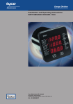
Installation and Operating Manual
Switchboard Integra 1540, 1000, 0640, 0440
0340 & 0240 Digital Metering Systems
Tyco Electronics UK Limited
Crompton Instruments
Freebournes Road, Witham, Essex, CM8 3AH, UK
Tel: +44 1376 509 509
Fax: +44 1376 509 511
Crompton
Switchboard Integra
Multifunctional metering for
Three-phase Electrical Systems
Models 1540, 1000, 0640, 0440, 0340, 0240
Operating Instructions
Important safety information is contained in the seperate installation leaflet.
Installers must familarise themselves with this information before installation
Crompton Instruments
Freebournes Road
Witham
Essex
CM8 3AH
England
Tel: +44 (0) 1376 509 509
Fax: +44 (0) 1376 509 511
E-Mail: [email protected]
Integra 1540, 1000, 0640, 0440, 0340, 0240 Issue 1 04/03
Contents
Page
1 Introduction
5
1.1
Unit Characteristics
6
1.1.1
0240
6
1.1.2
0340
6
1.1.3
0440 and 0640
6
1.1.4
1000
7
1.1.5
1540
8
1.2
Maximum Power
9
1.3
Secondary Voltage
9
1.4
Demand Calculation
9
1.5
RS485 Serial Option
10
1.6
Pulse Output Option
10
1.7
Analogue Output Option
10
2 Display Screens
11
2.1
Layout
11
2.2
Start Up Screens
11
2.3
System Screen
12
2.4
System %THD Screen
13
2.5
Line to Neutral Voltages
13
2.6
Line to Neutral Voltage %THD
13
2.7
Line to Line Voltages
14
2.8
Line to Line Voltages %THD
14
2.9
Line Currents
14
2.10
Line Currents %THD
15
2.11
Neutral Current, Frequency and Power Factor
15
2.12
Power
15
2.13
Active Energy (kWh)
16
2.14
Reactive Energy (kVArh)
16
Integra 1540, 1000, 0640, 0440, 0340, 0240 Issue 1 04/03
1
Contents
Page
2.15
Demand
17
2.16
Maximum Demand
17
2.17
Over Range
17
2.18
kWh and kVArh Display Range
18
2.19
Error Messages
18
3.1
Introduction
18
3.2
Number Entry Procedure
19
3.3
Access
21
3.3.1
Access with No Password Protection
21
3.3.2
Access with Password Protection
21
3.4
Changing the Password
23
3.5
Full Scale Current
24
3.6
Potential Transformer Primary Voltage
24
3 Setting up
18
3.7
Potential Transformer Secondary Value
26
3.8
Demand Integration Time
27
3.9
Resets
28
3.10
Pulsed Output, Pulse Duration
29
3.11
Pulse Rate
30
3.12
RS485 Baud Rate
31
3.13
RS485 Parity Selection
32
3.14
RS485 Modbus Address
33
3.15
Analogue Output Set Up
34
3.15.1 Introduction
34
3.15.2 Analogue Output Scaling Example
35
3.15.3 Power Factor
36
3.15.4 Phase Angle
39
3.15.5 Parameters available for analogue outputs
40
3.15.6 Reading (Parameter Selection) - A1r or A2r
41
3.15.7 Reading Top – A1rt or A2rt
42
2
Integra 1540, 1000, 0640, 0440, 0340, 0240 Issue 1 04/03
Contents
Page
3.15.8 Reading Bottom - A1rb or A2rb
43
3.15.9 Output Top – A1ot or A2ot
43
3.15.10 Output Bottom – A1ob or A2ob
43
4 Specification
44
4.1
Display Only Versions
44
4.1.1
Input
44
4.1.2
Auxiliary Power Supply
44
4.1.3
EMC Standards
44
4.1.4
Safety
45
4.1.5
Insulation
45
4.1.6
Environmental
45
4.1.7
Enclosure
45
4.2
Display/Transducer Combined Versions
45
4.2.1
Inputs
45
4.2.2
Auxiliary Power Supply
46
4.2.3
Measuring Ranges
47
4.2.4
Accuracy
47
4.2.5
Reference conditions of influence quantities
47
4.2.6
EMC Standards
47
4.2.7
Safety
48
4.2.8
Insulation
48
4.2.9
Environmental
48
4.2.10 Enclosure
48
4.3
Display/Tranducer Combined 1000 and 1540
48
4.3.1
Inputs
48
4.3.2
Auxiliary Power Supply
49
4.3.3
Accuracy
49
4.3.4
Reference conditions
50
4.3.5
Reference conditions of influence quantities
50
Integra 1540, 1000, 0640, 0440, 0340, 0240 Issue 1 04/03
3
Contents
Page
4.3.6
Nominal range of use of influence
quantities for measurands
51
4.3.7
Functional ranges
51
4.3.8
Screen
51
4.3.9
Standards
51
4.3.10 Safety
52
4.3.11 Insulation
52
4.3.12 Environmental
52
4.3.13 Enclosure
52
4.3.14 Serial Communications Option
52
4.3.15 Active Energy Pulsed Output Option
53
4.3.16 Integra 1540 Only
53
5 Basis of measurement and calculations
54
6 Serial Communications
56
6.1
RS485 Port - Modbus or JC N2
56
6.2
Modbus® Implementation
56
6.3
RS485 Implementation of Johnson Controls Metasys
60
7. Maintenance
63
8 Appendix A CE Declaration of Conformity
64
4
Integra 1540, 1000, 0640, 0440, 0340, 0240 Issue 1 04/03
1 Introduction
This manual provides operating instructions for the Crompton Switchboard Integra series of
Digital Metering Systems. Some versions of the Integra incorporate the metering transducer
that provides the interface for the measurement of power supply parameters such as voltage,
current, power, frequency etc. In other versions, the display and transducer are separate,
interconnected units. The display allows the user to set up metering transducer parameters
and to monitor the measurements. Some Integra models can be supplied as either an integral
or display-only version, while others are only available in one format. This manual provides
user instructions.
A separate leaflet provides installation instructions.
Table1 lists the various models of Integra and shows their distinctive characteristics.
Table 1 Summary of Integra models
Model
0240
0340
0440
0640
1000
V
V
V
V
V
V
A
A
A
A
A
1540
V
A
F
F
PF
kW kWh THD Analogue
Serial
Pulse
F
F
F
PF
kW kWh
F
PF
kW kWh THD Analogue
option*
RS485
option
RS485
option
Pulse
option
Pulse
option
Freq
45-65 Hz
45-65 Hz
360-400 Hz
45-65 Hz
45-65 Hz
45-65 Hz
* When used with an 1560/80 transducer that includes analogue options.
Voltage and current readings are true RMS, up to the 15th harmonic (31st for 1560/80
transducer).
The unit can be powered from an auxiliary a.c. or d.c. supply that is separate from the metered
supply. Versions of each model are available to suit 100-250V 45-65 Hz a.c./d.c. and 12-48V d.c
nominal supplies.
In this manual, the graphic
0240
0340
0440
0640
1000
1540
is used to show the models to which a screen applies. Boxes are greyed out to show models
that do not have that type of screen.
0240
0340
0440
0640
1000
1540
This example indicates that the screen only applies to Models 1000 and 1540.
0240
0340
0440
0640
1000
1540 Option
This indicates that the screen is an option on models 1000 and 1540.
Important safety information is contained in the accompanying installation instructions.
Installers must familarise themselves with this information before installation.
Integra 1540, 1000, 0640, 0440, 0340, 0240 Issue 1 04/03
5
1.1 Unit Characteristics
1.1.1 0240
The 0240 will display the following parameters:
• System voltage (average of all phases)
• System frequency (Hz)
• Voltage line to neutral for each phase (4-wire systems only)
• Voltage line to line for each phase (calculated in 4-wire)
The 0240 has Set-up screens for potential transformer primary
and secondary voltages.
Default display
1.1.2 0340
The 0340 will display the following parameters:
• System voltage (average of all phases)
• System current (average of all phases)
• Voltage line to neutral for each phase (4-wire systems only)
• Voltage line to line for each phase (calculated in 4-wire)
• Current in each line.
The 0340 has Set-up screens for:
Default display
• Full-scale current value
• Potential transformer primary and secondary voltages.
1.1.3 0440 and 0640
The 0440 operates on a mains frequency of 400 Hz nominal
and the 0640 at 45-65 Hz. The units can measure and display
the following parameters:
• System voltage (average of all phases)
• System current (average of all phases)
• System frequency (Hz)
• Voltage line to neutral for each phase (4-wire systems only)
• Voltage line to line for each phase (calculated in 4-wire)
Default display
• Current in each line
The 0440 and 0640 have Set-up screens for:
• Full-scale current value
• Potential transformer primary and secondary voltages.
6
Integra 1540, 1000, 0640, 0440, 0340, 0240 Issue 1 04/03
1.1.4 1000
The 1000 will display the following parameters:
Default display
•
System voltage (average of all phases)
•
System current (average of all phases)
•
System frequency (Hz)
•
Voltage line to neutral for each phase (4-wire systems only)
•
Voltage line to line for each phase (calculated in 4-wire)
•
Current in each line
•
Neutral current1
•
Power Factor
•
Active Power (kW)
•
Reactive Power (kVAr)
•
Apparent Power (kVA)
•
Active Energy (kWh)2
•
Reactive Energy (kVArh)2
•
Total System Current Demand (AD)2
•
Total System Active Power Demand (kWD)2
•
Maximum Total System Current Demand (AD)2
•
Maximum Total System Active Power Demand (kWD)2
The 1000 has Set-up screens for:
•
Full-scale current value
•
Potential transformer - primary voltages.
•
Demand integration time and energy/demand resets
•
Pulse output duration and rate divisor (option)
•
RS485 serial Modbus parameters (option)
A pulsed relay output, indicating kWh, and an RS485 ModbusTM
output are available as optional extras. The Modbus output
option allows remote monitoring from a Modbus master.
1
Neutral referenced parameters are only available when used with 4-wire and single phase
configured transducers.
2
All energy and demand measurements are importing only unless connected as exporting unit.
Integra 1540, 1000, 0640, 0440, 0340, 0240 Issue 1 04/03
7
1.1.5 1540
The1540 is available either as a display unit operating in
conjunction with a 15xx measurement transducer or as a
self-contained unit incorporating a transducer. The unit can
measure and display the following:
Default display
•
System voltage (average of all phases)
•
System current (average of all phases)
•
System frequency (Hz)
•
Voltage line to neutral for each phase (4-wire systems only)
•
Voltage line to line for each phase (calculated in 4-wire)
•
Current in each line.
•
Neutral current1
•
Power Factor
•
Active Power (kW)2
•
Reactive Power (kVAr)2
•
Apparent Power (kVA)
•
Active Energy (kWh)2
•
Reactive Energy (kVArh)2
•
Total System Current Demand (Admd)2
•
Total System Active Power Demand (kWD)2
•
Maximum Total System Current Demand (AD)2
•
Maximum Total System Active Power Demand (kWD)2
The 1540 has Set-up screens for:
1
Neutral referenced parameters are only
available when used with 4-wire and
single phase configured transducers.
2
All energy and demand measurements
are importing only unless connected as
•
Full-scale current value
•
Potential transformer - primary and secondary voltages
(Dis 1540 and Integra 15xx)
•
Potential transformer - primary voltages (self contained)
•
Demand integration time and energy/demand resets
•
Pulse output duration and rate divisor (option)
•
RS485 serial Modbus parameters (option)
•
Analogue current output (option, with separate
transducer only)
A pulsed relay output, indicating kWhr (and Kvarh on the two
part Dis 1540 and Integra 15xx combination), and an RS485
ModbusTM output are available as optional extras. The Modbus
output option allows remote monitoring from another display
(not self contained) or a Modbus master.
exporting unit.
The Analogue current output option provides a current output
that indicates the value of a chosen parameter.
8
Integra 1540, 1000, 0640, 0440, 0340, 0240 Issue 1 04/03
1.2 Maximum Power
Products covered in this manual are limited to a maximum power of 360 MW. During set-up,
primary voltage and current setting are checked and the unit will not accept entries that breach
the 360 MW limit. This is covered in more detail in the sections that show primary voltage and
current set-up. The Maximum Power restriction of 360 MW refer to 120% of nominal current and
120% of nominal voltage, i.e. 250 MW nominal system power.
1.3 Secondary Voltage
0240
0340
0440
0640
1000
1540
Most of the products described in this manual allow the user to specify, within a range, the
secondary voltage of the potential transformer (PT) with which it is to be used. The exception is
the Integra 1000 and self contained Integra 1540, which has the PT secondary factory set. On the
Integra 1000/1540, the user cannot change this value.
1.4 Demand Calculation
0240
0340
0440
0640
1000
1540
The maximum power consumption of an installation is an important measurement, as most
power utilities base their charges on it. Many utilities use a thermal maximum demand indicator
(MDI) to measure this peak power consumption. An MDI averages the power consumed over a
number of minutes, reflecting the thermal load that the demand places on the supply system.
The Integra uses a sliding window algorithm to simulate the characteristics of a thermal MDI
instrument, with the demand being calculated once per minute.
The demand period can be reset, which allows synchronisation to other equipment. When it is
reset, the values in the Demand and Maximum Demand registers are set to zero.
Demand Integration Times can be set to 8, 15, 20 or 30 minutes.
The number of sub-intervals, i.e. the demand time in minutes, can be altered either by using the
Demand Integration Time set-up screen (see Section 3.8) or via the RS485 port, where available,
using the ModbusTM protocol.
During the initial period, when the elapsed time since the demands were last reset or since the
Integra was switched on is less than one minute, the maximum demands (current MaxAD and
power MaxkWD) will remain at zero and not follow the instantaneous demands.
Maximum Demand is the maximum power or current demand that has occurred since the unit
was last reset as detailed in Section 3.9 Resets.
Integra 1540, 1000, 0640, 0440, 0340, 0240 Issue 1 04/03
9
1.5 RS485 Serial Option
0240
0340
0440
0640
1000
1540 Option
This option is available on two-part (separate transducer and display) units
and on 1000 and self-contained 1540 units.
This option uses an RS485 serial port with Modbus or JC NII protocol to provide a means of
remotely monitoring and controlling the Integra unit. Both protocols are supplied in the same
unit. Communications automatically configure according to the protocol that is recognized when
the master sends a message.
Where the installation comprises separate display and transducer units, the display
communicates with the transducer using a modified Modbus protocol via the RS485 port. Such
a transducer may have two such ports, either or both of which can be used for connection to a
display. Where a port is available, it can be connected to a PC for control and monitoring
purposes.
Set-up screens are provided for setting up the Modbus port. See Sections 3.12 to 3.14. These
screens are not applicable for setting up a port connected to a display unit, as the characteristics
of such a port are preset. On a two-port unit, communications settings made from an Integra
display affect the other communications port, unless the second port is also connected to a
display, in which case the changes have no effect.
1.6 Pulse Output Option
0240
0340
0440
0640
1000
1540 Option
This option provides a relay pulse output indication of measured active energy (kWh). The unit
can produce one pulse for every 1, 10 or 100kW of energy consumed. Two-part 1540 display
units operating with 1560 or 1580 transducers can also produce a pulse for every 1000 kW of
energy consumed. The pulse divisor can be set from the Set-up screen as detailed in Section
3.11 Pulse Rate. The pulse width (duration) can be set as detailed in Section 3.10 Pulsed Output,
Pulse Duration. On two part units, two pulsed outputs are available with common pulse rate
divisions and pulse widths.
1.7 Analogue Output Option
0240
0340
0440
0640
1000
1540 Option
This option is available on two-part (separate transducer and display) units and provides an
analogue current output that indicates the value of a chosen parameter. The parameter can be
chosen and set up via the set-up screen as described in Section 3.15 Analogue Output Set Up.
10
Integra 1540, 1000, 0640, 0440, 0340, 0240 Issue 1 04/03
2 Display Screens
2.1 Layout
The screen is used in two main modes: display of measured
values and parameter setup.
In display mode, three measured values can be shown, one on
each row. For each row, the LED indicators show the parameter
being measured and the units.
The >> button moves between display screens.
Voltage display
In Set up mode, the top row shows an abbreviation of the
parameter name, the middle row shows the parameter value
being set and the bottom row is used for confirmation of the
entered value. In general, the
key changes a parameter value
and the >> key confirms a value and moves on to the next
screen.
This example is the potential transformer primary voltage
confirmation screen.
Setup confirmation screen
The example screens shown in this manual are those relating to the 1540 models – the most
complex. The screens for simpler models are similar except that some of the parameters and
values are omitted. Section 1.1 shows the default display screens for the various models.
2.2 Start Up Screens
Initially, when power is applied to the Integra Display, two
screens will appear. The first screen lights the LED’s and can be
used as a display LED check.
Integra 1540, 1000, 0640, 0440, 0340, 0240 Issue 1 04/03
11
The second screen indicates the firmware installed in the
display unit. This example states that the version is 0.008. The
version on a particular unit will differ in line with ongoing
development and improvements.
After a short delay, the default Display screen will appear.
Use the >> (Next) key to move from one screen to the next in the sequence. The sequence
depends on the supply configuration (single phase 2 or 3 wire, 3 phase 3 or 4 wire).
2.3 System Screen
0240
0340
0440
0640
1000
1540
The following sections show 3 and 4 wire systems.
Single phase 2 and 3 wire systems have similar display screens.
The system screen is the default display. It appears when the unit is energised after the start up
screens. Section 1.1 shows the default system screens for the various models.
System Average Voltage (Volts)*
System Average Line Current (Amps).
System Total Active Power (kW).
Pressing key >> moves to the next screen
* Line to Line for 3 wire systems, Line to Neutral for 4 wire and
single phase 3 wire systems.
12
Integra 1540, 1000, 0640, 0440, 0340, 0240 Issue 1 04/03
2.4 System %THD Screen
0240
0340
0440
0640
1000
1540
Average % Total Harmonic Distortion for System Voltages.
Average % Total Harmonic Distortion for System Currents.
Key >> moves to next screen.
2.5 Line to Neutral Voltages
0240
0340
0440
0640
1000
1540
Three phase, four wire systems only.
Voltage Line 1 to Neutral (Volts).
Voltage Line 2 to Neutral (Volts).
Voltage Line 3 to Neutral (Volts).
Key >> moves to next screen.
2.6 Line to Neutral Voltage %THD
0240
0340
0440
0640
1000
1540
Three-phase, four wire systems only.
%THD of Line 1 Voltage to Neutral.
%THD of Line 2 Voltage to Neutral.
%THD of Line 3 Voltage to Neutral.
Key >> moves to next screen.
Integra 1540, 1000, 0640, 0440, 0340, 0240 Issue 1 04/03
13
2.7 Line to Line Voltages
0240
0340
0440
0640
1000
1540
Voltage Line 1 to Line 2 (Volts).
Voltage Line 2 to Line 3 (Volts).
Voltage Line 3 to Line 1 (Volts).
Key >> moves to next screen.
2.8 Line to Line Voltages %THD
0240
0340
0440
0640
1000
1540
Three-phase, three wire systems only.
Line 1 to Line 2 Voltage %THD.
Line 2 to Line 3 Voltage %THD.
Line 3 to Line 1 Voltage %THD.
Key >> moves to next screen.
2.9 Line Currents
0240
0340
0440
0640
1000
1540
Line 1 Current (Amps).
Line 2 Current (Amps).
Line 3 Current (Amps).
Key >> moves to next screen.
14
Integra 1540, 1000, 0640, 0440, 0340, 0240 Issue 1 04/03
2.10 Line Currents %THD
0240
0340
0440
0640
1000
1540
Line 1 Current %THD.
Line 2 Current %THD.
Line 3 Current %THD.
Key >> moves to next screen.
2.11 Neutral Current, Frequency and Power Factor
0240
0340
0440
0640
1000
1540
Neutral Current (Amps).
(4-wire and single phase 3 wire system only).
Frequency (Hz).
Power Factor (0 to 1, on 1000 and combined 1540; sign (-)
prefix, on 1540 two part: prefix C indicates Capacitive load and
L = Inductive).
Key >> moves to next screen.
2.12 Power
0240
0340
0440
0640
1000
1540
Reactive Power (kVAr).
Apparent Power (kVA).
Active Power (kW).
Key >> moves to next screen.
Integra 1540, 1000, 0640, 0440, 0340, 0240 Issue 1 04/03
15
2.13 Active Energy (kWh)
0240
0340
0440
0640
1000
1540
This is the energy that has been consumed since the unit was last reset (see Section 3.9 Resets).
Active Energy (kWh)
7 digit reading i.e. 0001243.
Key >> moves to next screen.
2.14 Reactive Energy (kVArh)
0240
0340
0440
0640
1000
1540
This is the reactive energy that has been consumed since the unit was last reset (see Section 3.9
Resets). The reading shows the energy (kVArh) in the reactive component of the supply.
Reactive Energy (kVArh)
7 digit reading i.e. 0000102
Key >> moves to next screen.
16
Integra 1540, 1000, 0640, 0440, 0340, 0240 Issue 1 04/03
2.15 Demand
0240
0340
0440
0640
1000
1540
This screen displays the present demand, i.e. the maximum power and the maximum current
demanded during the defined integration window period. See Section 3.8 Demand Integration
Time.
System Total Active Power Demand (kWD)
System Total Current Demand (AD)
Key >> moves to the next screen.
2.16 Maximum Demand
0240
0340
0440
0640
1000
1540
This screen displays the maximum power and the maximum current that has been demanded
since the unit was last reset (see Section 3.9 Resets).
Maximum System Total Active Power Demand (kWD)
Maximum System Total current Demand (AD)
Key >> returns to the start of the sequence with the System
Screen
2.17 Over Range
The displayed values must be in the range –999 x 1000 to 9999 x 1000. Any parameter value
outside this range will cause the display to show overrange.
This situation will be indicated by displaying four bars in the
appropriate line:
The value on the middle line is over range.
Integra 1540, 1000, 0640, 0440, 0340, 0240 Issue 1 04/03
17
2.18 kWh and kVArh Display Range
0240
0340
0440
0640
1000
1540
The kWh and kVArh display range is limited to 9999999. If the unit is allowed to increment
beyond this value the count will either wrap back to zero (if the 1560/1580 transducer is set to 7
digit mode) or continue to be updated in the 1560/1580 transducer but the display will change to
seven bars. The value will continue to be available via the Modbus output.
2.19 Error Messages
The display repeatedly requests new values from the measurement processor. If there is a
problem obtaining these values, the display will continue to retry but will alert the user by
displaying the message Err1. This message may be seen briefly during conditions of extreme
electromagnetic interference with the normal display returning once the interference has ceased.
If the Err1 message persists, try interrupting, for ten seconds, the auxiliary supply (or supplies)
to the Integra (display and transducer). This may restore normal operation. Also check that
auxiliary power is reaching the transducer and is within specification. Check that there are no
problems with the communications cable between the display and transducer, where applicable.
3 Setting up
3.1 Introduction
The following sections give step by step procedures for configuring the Integra transducer for a
particular installation using an attached display.
To access the Set-up screens, press and hold the
(Adjust) key and the >> (Next) keys
simultaneously for five seconds. This brings up the password entry stage. (See Section 3.3
Access).
On completion of the last Set-up screen, the program exits Set-up mode and returns to the last
selected Display screen. To return to the Display screens at any time during the set up
procedures, press the
and the >> keys simultaneously for five seconds.
18
Integra 1540, 1000, 0640, 0440, 0340, 0240 Issue 1 04/03
3.2 Number Entry Procedure
When setting up the unit, many screens require the setting up of a number, usually on the
middle row of digits. In particular, on entry to the setting up section, a password must be
entered. The procedure is as follows:
In general, press the
(adjust) key to change something on the current screen. Pressing the >>
(next) key normally leaves the current screen unchanged and brings up the next screen.
The example below shows how the number 0000 can be changed to 1234.
The digits are set one at a time, from left to right. The decimal
point to the right of the digit (* in the picture) flashes to
indicate which digit can currently be changed. It thus acts as a
cursor. Where the cursor coincides with a genuine decimal
point on the display, the decimal point will flash.
Press the
key to scroll the value of the first digit from 0
through to 9, the value will wrap from 9 round to 0. For this
example, set it to ‘1’.
First digit
Press the >> key to confirm your setting and advance to the
next digit.
Use the
key to set the second digit to the required value.
Press the >> key to confirm your selection and advance to the
next digit.
Second digit
Use the
key to set the third digit to the required value.
Press the >> key to confirm your selection and advance to the
next digit.
Third digit
Integra 1540, 1000, 0640, 0440, 0340, 0240 Issue 1 04/03
19
Use the
key to set the fourth digit to the required value.
Press the >> key to confirm your selection. If the unit accepts
your entry, the Confirmation screen will appear.
If the unit does not accept your entry, e.g. an incorrect
password, a rejection screen will appear, with dashes on the
bottom line.
Fourth digit
The Confirmation screen shows the entered number on the
bottom row with all decimal points showing.
If the displayed number is correct, press the >> key to move to
the next Set-up screen.
If not, press the
key to return to restart the number entry.
The first digit entry screen will appear.
Confirmation
If a rejection screen appears, press the
entry procedure.
key to restart the
Rejection
20
Integra 1540, 1000, 0640, 0440, 0340, 0240 Issue 1 04/03
3.3 Access
To access the Set-up screens, press the
Password Introduction screen appears.
and >> keys simultaneously for five seconds, until the
Password protection can be enabled to prevent unauthorised access to Set-up screens.
Password protection is not normally enabled when a product is shipped. The unit is protected if
the password is set to any four digit number other than 0000. Setting a password of 0000
disables the password protection.
3.3.1 Access with No Password Protection
Press >> from the Password Introduction screen. The 0000
password confirmation screen will appear.
Password introduction
Press >> again to proceed to the first Set-up screen.
0000 Password confirmation
3.3.2 Access with Password Protection
If the unit is protected by a password, proceed as follows:
Password introduction
Integra 1540, 1000, 0640, 0440, 0340, 0240 Issue 1 04/03
21
Enter the four-digit password using the method described in
Section 3.2 Number Entry Procedure.
First digit
On pressing >> to confirm the last digit, the Confirmation
screen will appear, provided the password is correct.
From the Password Confirmation screen, there is the option of
changing the password, as described in Section 3.4 Changing
the Password.
To proceed to the first Set-up screen, press >>.
Password Confirmation
If the password is incorrect, the Password Request screen will
reappear to permit a retry. Press
to start a retry or >> to exit
to the Display screens.
Password Incorrect
22
Integra 1540, 1000, 0640, 0440, 0340, 0240 Issue 1 04/03
3.4 Changing the Password
The option to change the password is only available from the Password Confirmation screen
immediately after the user has entered the existing password, if applicable.
Press
to start changing the password.
The password screen for the first digit will appear, with the old
password on the bottom line.
Password Confirmation
Set up the new password on the bottom line, as described in
Section 3.2 Number Entry Procedure.
On pressing >> to confirm the last digit, the Password
Confirmation screen will appear.
First new password digit
Press >> to confirm the new password. The first Set-up screen
will appear.
Press
to try again. The first digit screen will appear again.
New password
confirmation
Integra 1540, 1000, 0640, 0440, 0340, 0240 Issue 1 04/03
23
3.5 Full Scale Current
0240
0340
0440
0640
1000
1540
This parameter is the value of nominal Full Scale Currents that will be displayed as the Line
Currents. This screen enables the user to display the Line Currents inclusive of any transformer
ratios. The values displayed represent the current in amps. For example setting 800 on this
screen will cause the display to indicate 800 amps when the nominal maximum (typically 5A or
factory build option of 1A) current flows through the transducer current inputs.The maximum
value is as specification.
Press >> to accept the present value and move on to the next
Set-up screen (Section 3.6 Potential Transformer Primary
Voltage).
To change the Full Scale Current, press
and change the
current value as detailed in Section 3.2 Number Entry
Procedure. If the presently displayed current, together with the
full scale voltage value, results in an absolute maximum power
(120% of nominal current and voltage) of greater than 360
Megawatts, the range of the most significant digit will be
restricted.
The Maximum Power restriction of 360 Megawatts refers to
120% of nominal current and 120% of nominal voltage, i.e. 250
Megawatts nominal system power.
Edit
When the least significant digit has been set, pressing the >> key will advance to the Full Scale
Current Confirmation stage.
The minimum value allowed is 1. The value will be forced to 1 if the display contains zero when
the >> key is pressed.
3.6 Potential Transformer Primary Voltage
0240
0340
0440
0640
1000
1540
This value is the nominal full scale voltage which will be displayed as L1-N, L2-N and L3-N for a
four wire system, L1-2, L2-3 and L3-1 in a three wire system or system volts for single phase.
This screen enables the user to display the line to neutral and line to line voltages inclusive of
any transformer ratios. The values displayed represent the voltage in kilovolts (note the x1000
indicator). For example, on a 2.2kV system with 110V potential transformer secondary, set 2.200
at this screen.
If there is no potential transformer (PT) in the system, i.e. the voltage terminals are connected
directly to the metered voltage, leave this value unchanged and skip this set up step.
If the PT primary and secondary values are changed and it is desired to revert to a set-up with
no PT, then set both PT primary and secondary values to the nominal maximum voltage for the
Integra transducer.
24
Integra 1540, 1000, 0640, 0440, 0340, 0240 Issue 1 04/03
To set up the PT primary, proceed as follows:
To accept the currently displayed value, press >>. The screen
will move on to the next Set-up screen (Section 3.7 Potential
Transformer Secondary Value).
Press
to change the PT Primary voltage.
Initially all the digits of the present value will be flashing and
the decimal point position will be illuminated. This is to indicate
that initially the ‘multiplier’ must be selected. Press
to set the
decimal point position.
Note that the x1000 indicator is on.
Decimal Point
Press >> to accept the displayed (decimal point position). The
digits stop flashing and the PT Primary Value screen appears
Set the display to read the value of the PT Primary voltage,
using the method described in Section 3.2 Number Entry
Procedure. The primary voltage that can be set will be
restricted to a value such that, together with the full scale
current value (previously set), the absolute maximum power
(120% of nominal current and voltage) cannot exceed 360
Megawatts.
After the last digit has been accepted, the Confirmation screen
will appear.
Digit Edit
This example confirmation screen shows a primary voltage
setting of 2.2 kV.
Press >> to accept the displayed PT Primary Voltage. The next
Set-up screen will appear (Section 3.7 Potential Transformer
Secondary Value).
To change the displayed value, press
screen will reappear.
Confirmation
Integra 1540, 1000, 0640, 0440, 0340, 0240 Issue 1 04/03
25
. The Decimal Point
3.7 Potential Transformer Secondary Value
0240
0340
0440
0640
1000
1540
In Model 1000 and 1540 combined, the PT Secondary Value is factory set, as marked on the
barrel. The PT Secondary Value is user programmable on the 1540 and Integra 1560 two part.
This value must be set to the nominal full scale secondary voltage which will be obtained from
the transformer when the potential transformer (PT) primary is supplied with the voltage defined
in Section 3.6 Potential Transformer Primary Voltage. This defines the actual full scale voltage
that will be obtained from the PT secondary and measured by the unit. The ratio of the full scale
primary to full scale secondary voltage is the transformer ratio. Given full scale primary and
secondary voltages, the unit knows what primary voltage to display for any given measured
secondary voltage.
The secondary voltage displayed is in volts. Following the previous example, on a 2.2 kV system
with 110V PT secondary, set this screen to 110.0.
If there is no PT associated with this unit, leave this value unchanged and skip this step.
To accept the displayed PT Secondary Voltage, press >>. The
next Set-up screen will appear (Section 3.8 Demand Integration
Time).
To change the PT Secondary Voltage display, press
.
Note that the decimal point edit screen will only appear when
the display unit is connected to a transducer designed for
connection to voltages in the range 57.7 to 139V.
Decimal Point
Initially all the digits of the present value will be flashing and
the decimal point position will be illuminated. This is to indicate
that initially the ‘multiplier’ must be selected.
Press
to change the decimal point position.
Press >> to accept the decimal point position. The Digit Edit
screen appears.
Set the display to read the value of the PT Secondary voltage,
as described in Section 3.2 Number Entry Procedure.
After the last digit has been set and accepted, the Confirmation
screen will appear.
Digit Edit
26
Integra 1540, 1000, 0640, 0440, 0340, 0240 Issue 1 04/03
Press >> to accept the displayed value. Depending on the
model, this may take you out of the Set-up screens and back to
the last selected Display screen.
Press
to return to the Decimal Point screen.
The secondary value may only be set to values within the range
defined by the factory voltage build option. These nominal rms
input voltages are as shown in the relevant measurement
transducer specification (see separate document for two-part
products or Section 4.2.1 Inputs for combined products).
Confirmation
3.8 Demand Integration Time
0240
0340
0440
0640
1000
1540
This screen is used to set the period over which current and power readings are integrated (see
Section 1.4 Demand). The value displayed represents time in minutes.
To accept the displayed Demand Integration Time, press >>.
The next Set-up screen will appear (Section 3.9 Resets)
To change the Demand Integration Time, press
key to scroll through the available values.
and use this
Select the required value and press >> to accept it. The
Confirmation screen will appear.
Value
Press >> to accept the displayed value . The next Set-up screen
will appear (Section 3.9 Resets).
Press
to return to the Value screen and change the value.
Confirmation
Integra 1540, 1000, 0640, 0440, 0340, 0240 Issue 1 04/03
27
3.9 Resets
0240
0340
0440
0640
1000
1540
The following screens allow resetting of the Energy and Demand readings individually or
altogether.
Resetting the cumulative Energy (h) resets both Active and Reactive Energy.
Resetting Demand (d) resets:
• Active Power Demand
• Current Demand
• Maximum Active Power Demand
• Maximum Current Demand
Press >> to move on to the next Set-up screen without resetting
any readings.
To reset one or more readings press
(All) will appear.
. The first reset screen
Reset (None)
Use
to scroll through the parameters that can be reset:
h Active and reactive energy
d Demands and maximum demands
None – no reset
All – h and d combined.
Select the option required and press >> to confirm your
selection. The appropriate confirmation screen will appear.
Reset All
(The confirmation screen will not appear if None has been
selected.)
28
Integra 1540, 1000, 0640, 0440, 0340, 0240 Issue 1 04/03
Press
to return to the Reset screen.
Press >> to reset the selected reading(s). The next screen will
appear.
Confirmation
3.10 Pulsed Output, Pulse Duration
0240
0340
0440
0640
1000
1540 Option
This applies to the Relay Pulsed Output option only. Units with this option provide pulses to
indicate power consumption (kWh). See Section 1.6 pulse output option.
This screen allows the user to set the duration of the relay output pulse. The value displayed
represents the pulse duration in milliseconds (ms). On a two part DIS 1540/Integra 1560, this
screen will set the pulse duration for the Kvarh pulse relay (where fitted) also.
To retain the current setting, press >>. The next Set-up screen
will appear.
To change the pulse duration, press
Use the
and 200.
.
key to scroll through the available values of 60, 100
Select the value required and press >> to confirm your
selection. The confirmation screen will appear.
Edit
To change the value again, press
reappear.
. The Edit screen will
To accept the displayed pulse duration, press >>. The next
screen will appear. Depending on the model, this may take you
out of the Set-up screens and back to the last selected Display
screen.
Confirmation
Integra 1540, 1000, 0640, 0440, 0340, 0240 Issue 1 04/03
29
3.11 Pulse Rate
0240
0340
0440
0640
1000
1540 Option
This applies to the Relay Pulsed Output option only. Units with this option provide pulses to
indicate power consumption (kWh).
This screen allows setting of the kWh pulse rate divisor. On a two part DIS 1540/Integra 1560,
this screen will set the pulse rate for the kvarh pulse relay (where fitted) also. By default, the unit
produces one pulse per kWh. Changing this divisor changes the output pulse rate, as follows:
Divisor
One pulse per:
1
1 kWh
10
10 kWh
100
1000
100 kWh
1000 kWh (DIS1540 with 1560/1580 only)
Press >> to accept the currently displayed value. The next
Set-up screen will then appear.
To change the pulse rate divisor, press
.
Use the
key to scroll the value through the available values
1, 10, 100, 1,000. If the maximum power is greater than 3.6
megawatts, the range of divisors will be restricted to force an
upper limit to the number of pulses/hour of 3600.
Select the required divisor and press >> to confirm your
selection. The Confirmation screen will appear.
Edit
To change the value again, press
reappear.
. The Edit screen will
To accept the displayed value, press >>. The next Set-up screen
will appear.
Confirmation
30
Integra 1540, 1000, 0640, 0440, 0340, 0240 Issue 1 04/03
3.12 RS485 Baud Rate
0240
0340
0440
0640
1000
1540 Option
Use this screen to set the Baud Rate of the RS485 Modbus/JC NII port. The values displayed are
in kbaud.
Where the transducer unit may be separate from the display unit, the transducer has two
Modbus ports, at least one of which may be used for communicating with a display. The RS485
Baud Rate option only sets the Baud Rate for a port that is not communicating with a display
unit. The port characteristics for communication with a display are preset. If the JC NII protocol
is to be used, the baud rate must be set to 9.6.
If a display is detected on an RS485 port at start-up, any user settings for that port will be
ignored.
Press >> to accept the currently displayed value. The next
Set-up screen will then appear.
To change the baud rate, press
.
Use the
key to scroll through the available values 2.4, 4.8, 9.6
and 19.2.
Select the required baud rate and press >> to confirm your
selection. The Confirmation screen will appear.
Edit
Press >> to accept the new setting. The next Set-up screen will
appear.
To change the value again, press
reappear.
Confirmation
Integra 1540, 1000, 0640, 0440, 0340, 0240 Issue 1 04/03
31
. The Edit screen will
3.13 RS485 Parity Selection
0240
0340
0440
0640
1000
1540 Option
This screen allows setting of the parity and number of stop bits of the RS485 Modbus/JC II port.
Where the transducer unit is separate from the display unit, the transducer has two Modbus
ports, one of which may be used for communicating with a display. The RS485 Parity Selection
option only sets the parity for a port that is not communicating with a display unit. The port
characteristics for communication with a display are preset.
If the JC NII protocol is to be used, this parameter must be set to No parity and One stop bit.
Press >> to accept the currently displayed value. The next Setup screen will then appear.
To change the parity press
Use the
.
key to scroll through the available values:
odd – odd parity with one stop bit
E – even parity with one stop bit
no 1 – no parity one stop bit,
no 2 – no parity two stop bits.
Edit
Select the required setting and press >> to confirm your
selection. The Confirmation screen will appear.
Press >> to accept the new setting. The next Set-up screen will
appear.
Press
to return to the Edit screen.
Confirmation
32
Integra 1540, 1000, 0640, 0440, 0340, 0240 Issue 1 04/03
3.14 RS485 Modbus Address
0240
0340
0440
0640
1000
1540 Option
This screen allows setting of the Modbus/JC NII device address for the instrument.
Where the transducer unit is separate from the display unit, the transducer has two RS485 ports,
one of which may be used for communicating with a display. The Address option only sets the
address for a port that is not communicating with a display unit. The port characteristics for
communication with a display are preset.
Press >> to accept the currently displayed value. The next
Set-up screen will then appear.
To change the address, press
.
Set the three-digit address using the method described in
Section 3.2 Number Entry Procedure. The range of the
allowable addresses is 1 to 247. The range of selectable digits
is restricted so that no higher number can be set.
Press >> to confirm your selection. The Confirmation screen
will appear.
Edit
If the new address is correct, press >>. Depending on the
model, this may take you out of the Set-up screens and back to
the last selected Display screen.
If the new address is not correct, press
screen.
Confirmation
Integra 1540, 1000, 0640, 0440, 0340, 0240 Issue 1 04/03
33
to return to the Edit
3.15 Analogue Output Set Up
0240
0340
0440
0640
1000
1540 Option
This is an option on Models 1540 that have separate (1560 or 1580) transducers.
3.15.1 Introduction
This applies to the analogue output option only, allowing the parameter to be selected, and the
upper and lower limits adjusted, for either one or two channels.
For each analogue output fitted, provision is made for five values to be user selected. These are:
• A1r – Parameter, from Table 2. This is the measured input that is to be represented by the
analogue output, for example, Watts or Frequency.
• A1rt – Reading Top. This is the value of the electrical parameter that will cause the analogue
output to produce ‘Output Top’.
• A1rb – Reading Bottom. This is the value of the electrical parameter that will cause the
analogue output to produce ‘Output Bottom’.
• A1ot – Output Top. This is the value of output that will be reached when the measured
electrical parameter is at the reading top value.
• A1ob – Output Bottom. This is the value of output that will be reached when the measured
electrical parameter is at the reading bottom value.
To aid understanding, a simple example is shown in Section 3.15.2.
3.15.1.1 Second Channel
The screens following show the set-up for the first analogue channel. Set-up of the second
analogue output is identical except that screens show ‘A2’ instead of ‘A1’, i.e. A2r, A2rt, A2rb,
A2ot, A2ob.
At the end of the set up for the second analogue output pressing >> will exit the set up system
and enter the display mode.
3.15.1.2 Reverse Operation
It is possible to set reading top below reading bottom. In the example of Section 3.15.2, setting
reading top to 95 volts and reading bottom to 135 volts would cause the output current to
decrease from 20mA to 4mA as the measured voltage increased from 95 to 135 volts.
3.15.1.3 Reduced output range
Note that if the output values are adjusted to reduce output range, accuracy may be degraded.
For example, if a 0-20mA capable output is set to operate over 0-1mA, then the specified
accuracy will be degraded by a factor of 20.
34
Integra 1540, 1000, 0640, 0440, 0340, 0240 Issue 1 04/03
3.15.2 Analogue Output Scaling Example
In this example, the Integra has an output current range of 0 to 10mA and it is required that this
output range represents a reading range of 95 to 135V.
Example
Output top 10mA
135V Reading top
Analogue Output
current from unit
Reading Value
represented by Output
Output bottom 0mA
95V Reading bottom
3.15.2.1 Reading (A1r or A2r)
The measured electrical parameter that the analogue output will represent.
Example: Volts Ave (Average Voltage)
As shown in Table 2, any continuously variable parameter (volts, amps, watts etc) can be
selected for output as an analogue value. The table also shows those values that may be signed
(where the value may go negative).
3.15.2.2 Reading Top (A1rt or A2rt)
This is the value of the electrical parameter that will cause the analogue output to produce
‘Output Top’.
Example: 135 volts.
3.15.2.3 Reading Bottom (A1rb or A2rb)
This is the value of the electrical parameter that will cause the analogue output to produce
‘Output Bottom’.
Example: 95 volts.
This value may be set to any value between zero and 120% of nominal. (Or between –120% and
+120% of values that may be signed for example VAr)
3.15.2.4 Output
The two Output values specify the analogue current outputs that will represent the top and
bottom Reading values. They are included to allow additional versatility where particular
requirements prevail or to convert a 0-20mA output to 4-20mA. However it is suggested that, in
most other cases, these values should be set to the limits that the hardware can cover. The
range of the analogue output(s) for the unit is marked on the product label.
3.15.2.5 Output Top (A1ot or A2ot)
This is the value of output that will be reached when the measured electrical parameter is at the
reading top value.
Example: 10mA.
Integra 1540, 1000, 0640, 0440, 0340, 0240 Issue 1 04/03
35
3.15.2.6 Output Bottom (A1ob or A2ob)
This is the value of output that will be reached when the measured electrical parameter is at the
reading bottom value.
Example: 0mA
3.15.2.7 Summary
In the above example, the analogue output will be 0 mA when the average voltage is 95 volts,
5 mA at 115 volts and 10 mA at 135 volts.
3.15.3 Power Factor
When analogue output current is used to represent power factor, it can indicate the power factor
for an inductive or capacitive load on imported or exported power. This can be shown in two
dimensions as follows:
The polarity of the power factor reading indicates the direction of power flow:
Positive
PF relates to imported power
Negative
PF relates exported power.
This assumes that the unit is connected for a predominantly ‘import’ application. See Installation
sheet for further details.
36
Integra 1540, 1000, 0640, 0440, 0340, 0240 Issue 1 04/03
When setting up the analogue output for a power factor reading, the Reading Top value must be
in one of the left-hand quadrants and the Reading Bottom value must be in one of the righthand quadrants.
Hence, if the Reading Top value is set to –0.5, this will be a power factor of 0.5 for power
exported to an inductive load (bottom left-hand quadrant). Conversely, the Reading Bottom
value must be in one of the two right-hand quadrants. If the Reading Bottom value is set to –0.5,
this will be a power factor of 0.5 for power exported to a capacitive load (bottom right-hand
quadrant). Thus a power factor of +1 (for true power imported to a resistive load) is always
included in the analogue output range.
In specifying the Output Top and Output Bottom values, there are two conventions – one for
European areas of influence and one for North American areas. The two conventions are:
Europe
Output Top greater or more positive than Output Bottom.
USA
Output Top less or more negative than Output Bottom.
The examples below show cases where power is only imported and the load may be either
capacitive or inductive. The Reading Top and Reading Bottom values of zero ensure that the
whole range of possible (import) power factor readings is covered. The unit in the left-hand
example has an analogue output range of +1 to –1 mA and, since the Output Top value (+1 mA)
is more positive than the Output Bottom value (-1 mA), this arrangement complies with the
European convention. The right-hand example shows the North American convention.
In the above symmetrical arrangement, 0 mA corresponds to unity power factor. This is not the
case with the following asymmetrical arrangement.
Integra 1540, 1000, 0640, 0440, 0340, 0240 Issue 1 04/03
37
In the example above, the unit has an analogue output range of 0 to 1 mA, all power is imported
and the load is inductive. The 1 mA Output range covers a reading power factor range of 0.6,
from 0.9 capacitive to 0.5 inductive. The capacitive overlap is provided in case of overcompensation of power factor. The Output to Reading correlation is as follows:
Reading
European Convention
Output
North American Convention
Output
0.9 PF cap.
0 mA
1 mA
1 PF
0.167 mA
0.833 mA
0.9 PF ind.
0.333 mA
0.667 mA
0.8 PF ind.
0.500 mA
0.500 mA
0.7 PF ind.
0.667 mA
0.333 mA
0.6 PF ind.
0.833 mA
0.167 mA
0.5 PF ind.
1 mA
0 mA
38
Integra 1540, 1000, 0640, 0440, 0340, 0240 Issue 1 04/03
In this example, the unit is set to represent the full range of inductive and capacitive loads on
imported and exported power. The unit has an analogue output range of –1 to +1 mA. Both
Reading Top and Reading Bottom are set to –1 power factor.
3.15.4 Phase Angle
The Phase Angle analogue outputs are treated in a similar manner to Power Factor, with values
specified in degrees. The following figure shows the relationship between phase angle in
degrees and power factor.
Integra 1540, 1000, 0640, 0440, 0340, 0240 Issue 1 04/03
39
3.15.5 Parameters available for analogue outputs
Table 2 Analogue output parameter selection
Parameter
Number
1
2
3
4
5
6
7
8
9
10
11
12
13
14
15
16
17
18
19
20
21
22
24
25
27
29
31
32
34
36
43
44
53
54
101
102
Parameter
3Ø
4 wire
Volts 1 (L1 – N 4W or L1 – L2 3W)
Volts 2 (L2 – N 4W or L2 – L3 3W)
Volts 3 (L3 – N 4W or L3 – L1 3W)
Current 1
Current 2
Current 3
Watts Phase 1
Watts Phase 2
Watts Phase 3
VA Phase 1
VA Phase 2
VA Phase 3
VAr Phase 1
VAr Phase 2
VAr Phase 3
Power Factor Phase 1
Power Factor Phase 2
Power Factor Phase 3
Phase Angle Phase 1
Phase Angle Phase 2
Phase Angle Phase 3
Volts Ave
Current Ave
Current Sum
Watts Sum
VA Sum
VAr Sum
Power Factor Ave
Average Phase Angle
Frequency
W Demand Import
W Max. Demand Import
A Demand
A Max. Demand
V L1-L2 (calculated)
V L2-L3 (calculated)
40
3Ø
1Ø
1Ø
3 wire 3 wire 2 wire
✓
✓
✓
✓
✓
✓
✓
✓
✓
✓
✓
✓
✓
✓
✓
✓
✓
✓
✓
✓
+/-
✓
✓
✓
✓
✓
✓
✓
✓
✓
✓
✓
✓
✓
✓
✓
✓
✓
✓
✓
✓
✓
✓
✓
✓
✓
✓
✓
✓
✓
✓
✓
✓
✓
✓
✓
✓
✓
✓
✓
✓
✓
✓
✓
✓
✓
✓
✓
✓
✓
✓
✓
✓
✓
✓
✓
✓
✓
✓
✓
✓
✓
✓
✓
✓
✓
✓
✓
✓
✓
✓
✓
✓
✓
✓
✓
✓
✓
✓
✓
✓
✓
✓
✓
✓
✓
✓
✓
✓
✓
✓
✓
✓
✓
✓
✓
✓
✓
✓
✓
Integra 1540, 1000, 0640, 0440, 0340, 0240 Issue 1 04/03
Parameter
Number
103
104
113
118
119
120
121
122
123
125
126
Parameter
3Ø
4 wire
3Ø
1Ø
1Ø
3 wire 3 wire 2 wire
+/-
✓
V L3-L1 (calculated)
Average Line to Line Volts
Neutral Current
THD Volts 1
THD Volts 2
THD Volts 3
THD Current 1
THD Current 2
THD Current 3
THD Voltage Mean
THD Current Mean
✓
✓
✓
✓
✓
✓
✓
✓
✓
✓
✓
✓
✓
✓
✓
✓
✓
✓
✓
✓
✓
✓
✓
✓
✓
✓
✓
✓
✓
✓
✓
3.15.6 Reading (Parameter Selection) - A1r or A2r
Use this screen to choose the parameter that the analogue
Output current will represent. The number displayed on the
screen is the Parameter Number shown in Table 2.
If the displayed Parameter Number is already correct, press >>
to move on to the next Set-up screen.
To change the Parameter Number, press
and set the threedigit number using the method described in Section 3.2
Number Entry Procedure.
Parameter Selection
Press >> to confirm your selection. The Confirmation screen
will appear.
If the new Parameter Number is correct, press >>. The next
Set-up screen will appear.
If not, press
screen.
. You will be returned to the Parameter Selection
Confirmation
Integra 1540, 1000, 0640, 0440, 0340, 0240 Issue 1 04/03
41
3.15.7 Reading Top – A1rt or A2rt
The top reading is limited to 120% of the nominal maximum value of the parameter. For
example, a 230V nominal can be adjusted from 0 to 276V. The minimum is zero or –120% if the
parameter is signed.
This screen allows a negative value to be specified as the top
reading. It will only be available if the parameter selected on
the previous screen can be negative. For these parameters, the
+/- column of Table 2 has a tick (✓).
To accept the current value (‘-‘ for negative, no symbol for
positive), press >> to advance to the Alrb screen.
Use
to select the ‘-‘ sign for a negative Reading or no symbol
for a positive Reading.
Sign edit
Press >> to accept the current sign and advance to the next
screen.
Use this screen to set the position of the decimal point.
This screen will not appear when the selected parameter is
frequency, as there is no choice of decimal point position.
Pressing the
key will advance the decimal point position to
the right, illuminating the x1000 indicator as necessary and
wrapping the decimal point position when the highest available
position for the currently selected reading has been exceeded.
(Maximum resolution is 3 digits of the metered value.)
Decimal Point Position
Select the required decimal point position and press >> to
confirm your selection. The next screen will appear.
Use this screen to set the value of the Reading Top
Set the three-digit Reading Top value using the method
described in Section 3.2 Number Entry Procedure.
Press >> to confirm your selection. The Confirmation screen
will appear.
Value Entry
42
Integra 1540, 1000, 0640, 0440, 0340, 0240 Issue 1 04/03
Press >> to accept the displayed Reading Top value, The next
Set-up screen will appear.
Press
to return to the Edit screen.
Confirmation
3.15.8 Reading Bottom - A1rb or A2rb
Use these screens to specify the minimum or most negative value for the Reading Bottom value.
The method of setting the Reading Bottom screens is the same as for setting the Reading Top
screens, as described in Section 3.15.7. The Reading Bottom screens show A1rb (or A2rb for the
Analogue output 2) on the top line.
3.15.9 Output Top – A1ot or A2ot
Use these screens to set the maximum analogue output current (in mA). This current will
represent the highest reading value. You cannot specify a greater current than the actual value
that the unit can supply, e.g. 1 mA.
The method of setting the Output Top screens is the same as for setting the Reading Top
screens, as described in Section 3.15.7. The Output Top screens show A1ot (or A2ot for the
Analogue output 2) on the top line.
3.15.10 Output Bottom – A1ob or A2ob
Use these screens to set the minimum or most negative analogue output current (in mA). This
current will represent the lowest or most negative reading value. The current cannot be set to a
value that exceeds the actual capability of the unit, e.g. it cannot be set it to –10 mA if the unit
can only handle –1 mA.
The method of setting the Output Bottom screens is the same as for setting the Reading Top
screens, as described in Section 3.15.7. These screens show A1ob (or A2ob for Analogue output
2) on the top line.
Integra 1540, 1000, 0640, 0440, 0340, 0240 Issue 1 04/03
43
4 Specification
The parameters listed in this section apply only to those models that can measure those
parameters.
4.1 Display Only Versions
4.1.1 Input
RS485
Dedicated to Crompton Integra transducers
4.1.2 Auxiliary Power Supply
The unit can be powered from an auxiliary a.c. or d.c. supply that is separate from the metered
supply. Versions of the unit are available to suit 100-250V 45-65 Hz a.c./d.c. and 12-48V d.c
supplies.
4.1.2.1 High Voltage version
Standard nominal supply voltages
100 - 250V a.c. nominal ± 15% (85V a.c. absolute
minimum to 287V a.c. absolute maximum) or
100 - 250V d.c. nominal -15%, +25% (85V d.c. absolute
minimum to 312V d.c. absolute maximum)
A.C. supply frequency range
45 to 66 Hz or 360 to 440 Hz (Model 0440)
A.C. supply burden
4VA approx.
4.1.2.2 Low Voltage version
D.C.supply
12 - 48V d.c. -15% + 25% (10.2V d.c. absolute minimum
to 60V d.c. absolute maximum)
D.C. supply burden
4VA approx.
4.1.3 EMC Standards
EMC Immunity
EN61326 for Industrial Locations to performance
criterion A
EMC Emissions
EN61326 to Class A - Industrial
44
Integra 1540, 1000, 0640, 0440, 0340, 0240 Issue 1 04/03
4.1.4 Safety
IEC1010-1 (BSEN 61010-1) Permanently connected use, Normal Condition Installation category
III, pollution degree 2, Basic Insulation 300V RMS maximum. Auxilary circuits (12-48V auxiliary,
communications, relay and analogue outputs, where applicable) are separated from metering
inputs and 100-250V auxiliary circuits by at least basic insulation. Such auxiliary circuit terminals
are only suitable for connection to equipment which has no user accessible live parts. The
insulation for such auxiliary circuits must be rated for the highest voltage connected to the
instrument and suitable for single fault condition. The connection at the remote end of such
auxiliary circuits should not be accessible in normal use. Depending on application, equipment
connected to auxiliary circuits may vary widely. The choice of connected equipment or
combination of equipment should not diminish the level of user protection specified.
4.1.5 Insulation
Dielectric voltage withstand test
3.25kV RMS 50 Hz for 1 minute between all electrical
circuits
4.1.6 Environmental
Operating temperature
-10 to +60°C
Storage temperature
-20 to +85°C
Relative humidity
0 .. 95% non condensing
Shock
30g in 3 planes
Vibration
10 to 15 Hz @ 1.5 mm peak-peak
15 to 150 Hz @ 1.0g
Enclosure integrity (front face only)
IP54
4.1.7 Enclosure
Style
ANSI C39.1
Material
Polycarbonate front and base, steel case
Terminals
Screw clamp style
4.2 Display/Transducer Combined 0240, 0340, 0440, 0640
For Model 1000 and 1540 specification, refer to Section 4.3.
4.2.1 Inputs
Three phase three wire voltage range: ELV
100 - 120V L-L
LOV
121 - 240V L-L
Three phase four wire voltage range:
MIV
241 - 480V L-L
HIV
481 - 600V L-L
ELV
100 - 120V L-L (57.7 - 70V L-N)
Integra 1540, 1000, 0640, 0440, 0340, 0240 Issue 1 04/03
45
LOV
121 - 240V L-L (70.1 - 139V L-N)
MIV
241 - 480V L-L (140 - 277V L-N)
HIV
481 - 600V L-L (277 - 346V L-N)
(Voltage range is defined by factory build option.)
Nominal input voltage (a.c. rms)
57.7 to 346V L-N
100 to 600V L-L
System PT/VT primary values
1V to 400 kV
Max continuous input voltage
120% of nominal (up to 720 V max.)
Max short duration input voltage
Twice nominal (1s application repeated 10 times at
10s intervals)
Nominal input voltage burden
0.2 VA approx. per phase
Nominal input current
1 or 5 A a.c. rms
System CT primary values
Standard values up to 9999 Amps
(5 A secondaries)
(1 A on application)
Max continuous input current
120% of nominal
Max short duration current input
20 times nominal (1s application repeated 5 times at
5 min intervals)
Nominal input current burden
0.6 VA approx. per phase
4.2.2 Auxiliary Power Supply
The unit can be powered from an auxiliary a.c. or d.c. supply that is separate from the metered
supply. Versions of the unit are available to suit 100-200V 45-65 Hz a.c./d.c. and 12-48V d.c
supplies.
4.2.2.1 High Voltage version
Standard supply voltage
100 to 250V a.c. nominal ±15% (85V a.c. absolute
minimum to 287V a.c. absolute maximum) or 100V to
250V d.c. nominal +25%, -15% (85V d.c. absolute
minimum to 312V d.c. absolute maximum)
a.c. supply frequency range
45 to 66 Hz or 360 to 440 Hz (Model 0440)
a.c. supply burden
3W
4.2.2.2 Low Voltage version
d.c.supply
12 to 48V d.c.. nominal +25%, -15% (10.2V d.c. absolute
minimum to 60V d.c. absolute maximum)
d.c. supply burden
3W
46
Integra 1540, 1000, 0640, 0440, 0340, 0240 Issue 1 04/03
4.2.3 Measuring Ranges
Values of measured quantities for which errors are defined.
Voltage
70 .. 120% of nominal
Current
5 .. 120% of nominal
Frequency
45 .. 66 Hz, 360 .. 440 Hz (Model 0440)
Crest values of voltage and current must remain within
168% of nominal maximum rms values
4.2.4 Accuracy
Voltage
0.4% of reading ±0.1% of range
1% of range maximum for Model 0440
Current
0.4% of reading ±0.1% of range
1% of range maximum for Model 0440
Frequency (not 0340)
0.15% of mid frequency
1% of mid frequency for Model 0440
Temperature coefficient
0.013%/°C typical
Response time to step input
1.5 seconds approx.
Screen update time
0.5 second approx.
4.2.5 Reference conditions of influence quantities
Values that quantities which affect measurement errors to a minor degree
have to be for the intrinsic (headline) errors for measured quantities to apply.
Ambient temperature
23°C
Input frequency
50 or 60 Hz 2%
Input waveform Sinusoidal
(distortion factor 0.005)
Auxiliary supply voltage Nominal
1%
Auxiliary supply frequency Nominal
1%
Auxiliary supply distortion factor
Magnetic field of external origin
0.05
Terrestrial flux
4.2.6 EMC Standards
EMC Immunity EN61326 for Industrial Locations to performance criterion A
EMC Emissions EN61326 to Class B - Domestic
Integra 1540, 1000, 0640, 0440, 0340, 0240 Issue 1 04/03
47
4.2.7 Safety
IEC1010-1 (BSEN 61010-1) Permanently connected use, Normal Condition Installation category
III, pollution degree 2, Basic Insulation 720V RMS maximum. Auxiliary circuits (12-48V auxuliary,
communications, relay and analogue outputs, where applicable) are separated from metering
inputs and 100-250V auxiliary circuits by at least basic insulation. Such auxiliary circuit terminals
are only suitable for connection to equipment which has no user accessible live parts. The
insulation for such auxiliary circuits must be rated for the highest voltage connected to the
instrument and suitable for single fault condition. The connection at the remote end of such
auxiliary circuits should not be accessible in normal use. Depending on application, equipment
connected to auxiliary circuits may vary widely. The choice of connected equipment or
combination of equipment should not diminish the level of user protection specified.
4.2.8 Insulation
Dielectric voltage withstand test 3.25kV RMS 50Hz for 1 minute between all isolated
electrical circuits
4.2.9 Environmental
Operating temperature
-20 to +70°C
Storage temperature
-20 to +80°C
Relative humidity
0 .. 95% non condensing
Shock
30g in 3 planes
Vibration
10 to 15 Hz @ 1.5 mm peak-peak
15 to 150 Hz @ 1.0g
Enclosure integrity (front face only)
IP54
Harmonic distortion
max 50% THD up to 15th harmonic
4.2.10 Enclosure
Style
ANSI C39.1
Material
Polycarbonate front and base, steel case
Terminals
6-32 UNC slotted barrier type
Weight
1.3kg
4.3 Display/Tranducer Combined 1000 and 1540
See section 4.3.16 for specifications particular to the 1540
4.3.1 Inputs
Nominal input voltage (a.c. rms)
57.7 to 600V L-N (single phase)
100 to 600V L-L (3 wire)
57.7 to 346V L-N (4 wire)
System PT/VT primary values
1V to 400KV
48
Integra 1540, 1000, 0640, 0440, 0340, 0240 Issue 1 04/03
Max continuous input voltage
120% of nominal (up to 720V max.)
Max short duration input voltage
2*nominal (1s application repeated 10 times at
10s intervals)
Nominal input voltage burden
0.2VA approx. per phase
Nominal input current
1 or 5A a.c. rms
System CT primary values
Std. values up to 4kA (1 or 5 Amp secondaries)
Max continuous input current
120% of nominal
Max short duration current input
20*nominal (1s application repeated 5 times at
5 min intervals)
Nominal input current burden
0.6VA approx. per phase
4.3.2 Auxiliary Power Supply
The unit can be powered from an auxiliary a.c. or d.c. supply that is separate from the metered
supply. Versions of the unit are available to suit 100-200V 45-65 Hz a.c./d.c. and 12-48V d.c
supplies.
Standard supply voltage
100 to 250V a.c. nominal ±15% (85V a.c. absolute
minimum to 287V a.c. absolute maximum) or 100V to
250V d.c. nominal +25%, -15% (85V d.c. absolute
minimum to 312V d.c. absolute maximum)
a.c. supply frequency range
45 to 66 Hz or 360 to 440 Hz (Model 0440)
a.c. supply burden
3W
d.c.supply
12 to 48V d.c.. nominal +25%, -15% (10.2V d.c. absolute
minimum to 60V d.c. absolute maximum)
d.c. supply burden
3W
4.3.3 Accuracy
Voltage
0.4% of reading ±0.1% of range
Current
0.4% of reading ±0.1% of range
Neutral current
4% of range
Frequency
0.15% of mid frequency
Power factor
1% of Unity
Active power (W)
0.9% of reading ±0.1% of range
Reactive power (VAr)
1.9% of reading ±0.1% of range
Apparent power (VA)
0.9% of reading ±0.1% of range
Active energy (W.h)
1 Class (IEC 1036, Active PF 0.8-1-0.8 importing)
Reactive energy (VAr.h)
2%, Reactive PF 0.8-1-0.8 importing)
Temperature coefficient
0.013%/°C typical
Response time to step input
1.5 seconds approx.
Error change due to variation
of an influence quantity in the
manner described in section 6
Twice the error allowed for the reference
condition applied in the test.
Integra 1540, 1000, 0640, 0440, 0340, 0240 Issue 1 04/03
49
of IEC688:1992
Error in measurement when a
measurand is within its measuring
range, but outside its
reference range.
Twice the error allowed at the end of the reference
range adjacent to the section of the measuring
range where the measurand is currently operating
or being tested.
4.3.4 Reference conditions
Reference conditions of measurands and, where applicable, components of the measurand
Values of measured quantities, and of components of measured quantities, where the intrinsic
(headline) errors for the measured quantities apply.
Voltage
50 .. 100% of nominal
Current
10 .. 100% of nominal
Frequency
Nominal ±10%
Active power (Watt)
10 .. 100% of nominal
Voltage
Nominal ±2%
Current
10 .. 100% of nominal
Active power factor
1 .. 0.8 leading or lagging
Reactive power (VAr)
10 .. 100% of nominal
Voltage
Nominal ±2%
Current
10 .. 100% of nominal
Reactive power factor
1 .. 0.8 leading or lagging
Apparent Power (VA)
10 .. 100% of nominal
Voltage
Nominal ±2%
Current
10 .. 100% of nominal
Power factor
1 .. 0.8 leading or lagging
Voltage
Nominal ±2%
Current
40 .. 100% of nominal
4.3.5 Reference conditions of influence quantities
Values that quantities which affect measurement errors to a minor degree have to be for the
intrinsic (headline) errors for measured quantities to apply.
Ambient temperature
23°C
Input frequency
50 or 60 Hz ±2%
Input waveform
Sinusoidal (distortion factor 0.005)
Auxiliary supply voltage
Nominal ±1%
Auxiliary supply frequency
Nominal ±1%
Auxiliary supply distortion factor
0.05
Magnetic field of external origin
Terrestrial flux
50
Integra 1540, 1000, 0640, 0440, 0340, 0240 Issue 1 04/03
4.3.6 Nominal range of use of influence quantities for measurands
Values of quantities which affect measurement errors to a minor degree for which the
magnitude of the measurement error is defined in this specification.
Voltage
50 .. 120% of nominal
Current
5 .. 120% of nominal
Frequency
Nominal ±10%
Power factor (active/reactive
as appropriate)
0.5 lagging .. 1 .. 0.8 leading ,importing
Temperature
-20°C to +70°C
Input waveform distortion
20% 3rd Harmonic distortion
Auxiliary supply voltage
Nominal ±10%
Auxiliary supply frequency
Nominal ±10%
Magnetic field of external origin
400A/m
Crest values of voltage and current must remain within
168% of nominal maximum rms values
4.3.7 Functional ranges
The functional ranges of measurands and of influence quantities for measurands
Values of measured quantities, components of measured quantities, and quantities which affect
measurement errors to a minor degree, for which the product gives meaningful readings.
Voltage
5 .. 120% of nominal (below 5% of nominal voltage,
current indication is only approximate)
Current
0 .. 120% of nominal
(2 .. 120% of nominal for Power Factor)
Frequency
45 .. 66 Hz
Power Factor
1 .. 0 leading or lagging, importing (active/reactive as
appropriate)
Temperature
-20°C to +70°C
Active power (Watt)
0 .. 120% of nominal, 360 MW Max.
Reactive power (VAr)
0 .. 120% of nominal, 360 MVAr Max.
Apparent power (VA)
0 .. 120% of nominal, 360 MVA Max.
4.3.8 Screen
Update
0.5 second approx.
4.3.9 Standards
Terms, Definitions and Test Methods
IEC688 (BSEN 60688)
IEC1036 (BSEN 61036)
EMC
IEC 61326
Integra 1540, 1000, 0640, 0440, 0340, 0240 Issue 1 04/03
51
4.3.10 Safety
IEC1010-1 (BSEN 61010-1) Permanently connected use, Normal Condition Installation category III,
pollution degree 2, Basic Insulation 720V RMS maximum. Auxiliary circuits (12-48V auxuliary,
communications, relay and analogue outputs, where applicable) are separated from metering
inputs and 100-250V auxiliary circuits by at least basic insulation. Such auxiliary circuit terminals
are only suitable for connection to equipment which has no user accessible live parts. The
insulation for such auxiliary circuits must be rated for the highest voltage connected to the
instrument and suitable for single fault condition. The connection at the remote end of such
auxiliary circuits should not be accessible in normal use. Depending on application, equipment
connected to auxiliary circuits may vary widely. The choice of connected equipment or
combination of equipment should not diminish the level of user protection specified.
4.3.11 Insulation
Dielectric voltage withstand test 3.25kV RMS 50Hz for 1 minute between all isolated
electrical circuits
4.3.12 Environmental
Operating temperature
-20°C to +70°C
Storage temperature
-20°C to +80°C
Relative humidity
0 .. 95% non condensing
Warm up time
1 minute
Shock
30g in 3 planes
Vibration
10 to 15 Hz @ 1.5 mm peak-peak
15 to 150 Hz @ 1.0g
Enclosure code (front)
IP54
Harmonic distortion
max 50% THD up to 15th harmonic
4.3.13 Enclosure
Style
ANSI C39.1 or JIS C-1102
Material
Polycarbonate Front, Steel case
Terminals
6-32 UNC slotted barrier style.
Weight
1.3kg
4.3.14 Serial Communications Option
Protocol
MODBUS (RS485)
Baud rate
19200, 9600, 4800 or 2400 (programmable)
Parity
Odd or Even, with 1 stop bit, or None with 1 or 2 stop bits.
52
Integra 1540, 1000, 0640, 0440, 0340, 0240 Issue 1 04/03
4.3.15 Active Energy Pulsed Output Option
Rated
SPNO, 100V dc, 0.5A Max.
Default pulse rate
1 per kWhr
Pulse rate divisors
1
10 (yielding 1 pulse per 10 kWhr)
100 (yielding 1 pulse per 100 kWhr)
Pulse duration
60ms, 100ms or 200ms, 3600 Pulses per hour max
4.3.16 Integra 1540 Only
Measuring Range: Total Harmonic
Distortion:
Up to 15th Harmonic 0%-50%
Accuracy:
Total Harmonic Distortion 1%
Reference conditions of measurands:
Voltage: 60% to 100% of nominal for THD
Reference conditions of measurands:
Total Harmonic Distortion: 20% to 100% of nominal for THD
Reference conditions of measurands:
Total Harmonic Distortion: 0-30%
Integra 1540, 1000, 0640, 0440, 0340, 0240 Issue 1 04/03
53
5 Basis of measurement and calculations
Reactive and Apparent Power
Active powers are calculated directly by multiplication of voltage and current. Reactive powers
are calculated using frequency corrected quarter phase time delay method. Apparent power is
calculated as the square root of sum of squares of active and reactive powers. For 4 wire
products, overall powers are the sum of the per phase powers. For 3 phase 3 wire products, the
"two wattmeter" method is used for overall powers.
Energy resolution
Cumulative energy counts are reported using the standard IEEE floating point format. Reported
energy values in excess of 16MWh may show a small non cumulative error due to the
limitations of the number format. Internally the count is maintained with greater precision.
The reporting error is less than 1 part per million and will be automatically corrected when the
count increases.
Power Factor
The magnitude of Per Phase Power Factor is derived from the per phase active power and per
phase apparent power. The power factor value sign is set to negative for an inductive load and
positive for a capacitive load.
The magnitude of the System Power Factor is derived from the sum of the per phase active
power and per phase apparent power. The system power factor value sign is set to negative for
an inductive load and positive for a capacitive load. The load type, capacitive or inductive, is
determined from the signs of the sums of the relevant active powers and reactive powers. If
both signs are the same, then the load is inductive, if the signs are different then the load is
capacitive.
The magnitude of the phase angle is the ArcCos of the power factor. It's sign is taken as the
opposite of the var's sign.
Maximum Demand
The maximum power consumption of an installation is an important measurement as power
utilities often levy related charges. Many utilities use a thermal maximum demand indicator
(MDI) to measure this peak power consumption. An MDI averages the power consumed over a
number of minutes, such that short surges do not give an artificially high reading.
Integra uses a sliding window algorithm to simulate the characteristics of a thermal MDI
instrument, with the demand period being updated every minute.
The demand period can be reset, which allows synchronisation to other equipment. When it is
reset, the values in the Demand and Maximum Demand registers are set to zero.
54
Integra 1540, 1000, 0640, 0440, 0340, 0240 Issue 1 04/03
Time Integration Periods can be set to 8, 15, 20 or 30 minutes.
Note: During the initial period when the "sliding window" does not yet contain a full set of
readings (i.e. the elapsed time since the demands were last reset or the elapsed time since
Integra was switched on is less than the selected demand period) then maximum demands may
not be true due to the absence of immediate historical data.
The Time Integration Period can be user set either from the Integra 1540 Display or by using the
communications option.
Total Harmonic Distortion (1540 only)
The calculation used for the Total Harmonic Distortion is:
THD = ((RMS of total waveform - RMS of fundamental) / RMS of total waveform) x 100
This is often referred to as THD - R
The figure is limited to the range 0 to 100% and is subject to the 'range of use' limits. The
instrument may give erratic or incorrect readings where the THD is very high and the
fundamental is essentially suppressed.
For low signal levels the noise contributions from the signal may represent a significant portion
of the "RMS of total waveform" and may thus generate unexpectedly high values of THD. To
avoid indicating large figures of THD for low signal levels the product will produce a display of 0
(zero).
Typically, display of THD will only produce the 0 (zero) value when the THD calculation has been
suppressed due to a low signal level being detected. It should also be noted that spurious
signals (for example, switching spikes) if coincident with the waveform sampling period will be
included in the "RMS of the total waveform" and will be used in the calculation of THD.
The display of THD may be seen to fluctuate under these conditions.
Integra 1540, 1000, 0640, 0440, 0340, 0240 Issue 1 04/03
55
6 Serial Communications
6.1. RS485 Port – Modbus or JC N2
0240
0340
0440 0640
1000 1540 Option
INTEGRA 1000 and 1540 offer the option of an RS485 communication port for direct connection
to SCADA systems. This port can be used for either an RS485 Modbus RTU slave, or as a
Johnson Controls N2 protocol slave. Choice of reply protocol is made by the Integra on the
basis of the format of request, so that a Modbus request receives a Modbus reply, and an N2
protocol request receives an N2 protocol reply.
6.2 Modbus® Implementation
This section provides basic information for the integration of the product to a Modbus network.
If background information or more details of the Integra implementation is required please refer
to our “Guide to RS485 Communications and the Modbus Protocol”, available on our CD
catalogue or from any recognised supplier.
The Modbus‚ protocol establishes the format for the master's query by placing into it the device
address, a function code defining the requested action, any data to be sent, and an error
checking field. The slave's response message is also constructed using Modbus protocol. It
contains fields confirming the action taken, any data to be returned, and an error-checking field.
If an error occurs in receipt of the message, or if the slave is unable to perform the requested
action, the slave will construct an error message and send it as it’s response. Framing errors
receive no response from the Integra.
The electrical interface is 2-wire RS485, via 3 screw terminals. Connection should be made using
twisted pair screened cable (Typically 22 gauge Belden 8761 or equivalent). All "A" and "B"
connections are daisy chained together. The screens should also be connected to the “Gnd”
terminal. To avoid the possibility of loop currents, an Earth connection should be made at only
one point on the network.
Line topology may or may not require terminating loads depending on the type and length of
cable used. Loop (ring) topology does not require any termination load.
The impedance of the termination load should match the impedance of the cable and be at both
ends of the line. The cable should be terminated at each end with a 120 ohm (0.25 Watt min.)
resistor.
A total maximum length of 3900 feet (1200 metres) is allowed for the RS485 network. A
maximum of 32 electrical nodes can be connected, including the controller.
The address of each Integra 1000/1540 can be set to any value between 1 and 247. Broadcast
mode (address 0) is not supported.
The maximum latency time of an Integra 1000/1540 is 150ms i.e. this is the amount of time that
can pass before the first response character is output. The supervisory programme must allow
this period of time to elapse before assuming that the Integra is not going to respond.
56
Integra 1540, 1000, 0640, 0440, 0340, 0240 Issue 1 04/03
The data format in RTU mode is:
Coding System:
Data Format:
8-bit per byte
4 bytes (2 registers) per parameter.
Floating point format ( to IEEE 754)
Most significant register first (Default). The default may be changed if
required - See Holding Register "Register Order" parameter.
Error Check Field:
2 byte Cyclical Redundancy Check (CRC)
Framing:
1
8
1
1
start bit
data bits, least significant bit sent first
bit for even/odd parity or no parity
stop bit if parity is used; 1 or 2 bits if no parity
Data Transmission speed is selectable between 2400, 4800, 9600 and 19200 baud.
Input Registers
Input registers are used to indicate the present values of the measured and calculated electrical
quantities.
Each parameter is held in two consecutive 16 bit registers. The following table details the 3X
register address, and the values of the address bytes within the message. A tick (÷) in the
column indicates that the parameter is valid for the particular wiring system. Any parameter
with a cross (X) will return the value Zero (0000h). Some parameters are only available on the
Integra 1540, as shown in the table below..
Each parameter is held in the 3X registers. Modbus Function Code 04 is used to access all
parameters.
e.g. to request
Volts 1
Start address
No of registers
Volts 2
Start address
No of registers
=
=
=
=
00
02
02
02
Each request for data must be restricted to 40 parameters or less. Exceeding the 40 parameter
limit will cause a Modbus exception code to be returned.
Integra 1540, 1000, 0640, 0440, 0340, 0240 Issue 1 04/03
57
Register
Parameter
Number
30001
30003
30005
30007
30009
30011
30013
30015
30017
30019
30021
30023
30025
30027
30029
30031
30033
30035
30037
30039
30041
30043
30047
30049
30053
30057
30061
30063
30067
30071
30073
30077
30085
30087
30105
30107
30201
30203
30205
30207
30225
30235
30237
30239
30241
30243
30245
30249
30251
30255
1
2
3
4
5
6
7
8
9
10
11
12
13
14
15
16
17
18
19
20
21
22
24
25
27
29
31
32
34
36
37
39
43
44
53
54
101
102
103
104
113
118
119
120
121
122
123
125
126
128
Parameter
Volts 1 (L1 – N 4W or L1 – L2 3W)
Volts 2 (L2 – N 4W or L2 – L3 3W)
Volts 3 (L3 – N 4W or L3 – L1 3W)
Current 1
Current 2
Current 3
Watts Phase 1 - Integra 1540 only
Watts Phase 2 - Integra 1540 only
Watts Phase 3 - Integra 1540 only
VA Phase 1 - Integra 1540 only
VA Phase 2 - Integra 1540 only
VA Phase 3 - Integra 1540 only
var Phase 1 - Integra 1540 only
var Phase 2 - Integra 1540 only
var Phase 3 - Integra 1540 only
Power Factor Phase 1 - Integra 1540 only
Power Factor Phase 2 - Integra 1540 only
Power Factor Phase 3 - Integra 1540 only
Phase Angle Phase 1 - Integra 1540 only
Phase Angle Phase 2 - Integra 1540 only
Phase Angle Phase 3 - Integra 1540 only
Volts Ave
Current Ave
Current Sum - Integra 1540 only
Watts Sum
VA Sum
var Sum
Power Factor Ave
Average Phase Angle - Integra 1540 only
Frequency
Wh Import
varh Import
W Demand Import
W Max. Demand Import
A Demand
A Max. Demand
V L1-L2
(calculated)
V L2-L3
(calculated)
V L3-L1
(calculated)
Average Line to Line Volts
Neutral Current
THD Volts 1 - Integra 1540 only
THD Volts 2 - Integra 1540 only
THD Volts 3 - Integra 1540 only
THD Current 1 - Integra 1540 only
THD Current 2 - Integra 1540 only
THD Current 3 - Integra 1540 only
THD Voltage Mean - Integra 1540 only
THD Current Mean - Integra 1540 only
Power Factor (+Ind/-Cap)
58
Modbus Start
3Ø
3Ø
1Ø
1Ø
Address Hex
4 wire 3 wire 3 wire 2 wire
High Byte Low Byte
00
00
✓
✓
✓
✓
00
02
✓
✓
✓
X
00
04
✓
✓
X
X
00
06
✓
✓
✓
✓
00
08
✓
✓
✓
X
00
0A
✓
✓
X
X
00
0C
✓
X
✓
✓
00
0E
✓
X
✓
X
00
10
✓
X
X
X
00
12
✓
X
✓
✓
00
14
✓
X
✓
X
00
16
✓
X
X
X
00
18
✓
X
✓
✓
00
1A
✓
X
✓
X
00
1C
✓
X
X
X
00
1E
✓
X
✓
✓
00
20
✓
X
✓
X
00
22
✓
X
X
X
00
24
✓
X
✓
✓
00
26
✓
X
✓
X
00
28
✓
X
X
X
00
2A
✓
✓
✓
✓
00
2E
✓
✓
✓
✓
00
30
✓
✓
✓
✓
00
34
✓
✓
✓
✓
00
38
✓
✓
✓
✓
00
3C
✓
✓
✓
✓
00
3E
✓
✓
✓
✓
00
42
✓
✓
✓
✓
00
46
✓
✓
✓
✓
00
48
✓
✓
✓
✓
00
4C
✓
✓
✓
✓
00
54
✓
✓
✓
✓
00
56
✓
✓
✓
✓
00
68
✓
✓
✓
✓
00
6A
✓
✓
✓
✓
00
C8
✓
X
✓
X
00
CA
✓
X
X
X
00
CC
✓
X
X
X
00
CE
✓
X
✓
X
00
E0
✓
X
✓
✓
00
EA
✓
✓
✓
✓
00
EC
✓
✓
✓
X
00
EE
✓
✓
X
X
00
F0
✓
✓
✓
✓
00
F2
✓
✓
✓
X
00
F4
✓
✓
X
X
00
F8
✓
✓
✓
✓
00
FA
✓
✓
✓
✓
00
FE
✓
✓
✓
✓
Integra 1540, 1000, 0640, 0440, 0340, 0240 Issue 1 04/03
Modbus Holding Registers and Integra set up
Holding registers are used to store and display instrument configuration settings. All holding
registers not listed in the table below should be considered as reserved for manufacturer use
and no attempt should be made to modify their values.
The demand parameters may be viewed or changed using the Modbus protocol. Each parameter
is held in the 4X registers. Modbus Function Code 03 is used to read the parameter and Function
Code 16 is used to write.
Register
Parameter
40001
40003
40007
40009
40011
40013
40015
40023
40025
40037
40041
40299
1
2
4
5
6
7
8
12
13
19
21
150
Parameter
Number
Modbus Start
Address Hex
High
Low
Byte
Byte
00
00
00
02
00
06
00
08
00
0A
00
0C
00
0E
00
16
00
18
00
24
00
28
01
2A
Demand Time
Demand Period
System Voltage
System Current
System Type
Relay Pulse Width
Energy Reset
Pulse Divisor
Password
System Power
Register Order
Secondary Volts
Valid range
0 only
8,15,20,30 minutes.
1V - 400kV
1-9999 A
3,5,10 (x20mS)
0 only
1,10,100,1000
0000-9999
2141.0 only
Min Vin-Max Vin
Mode
r/w
r/w
r/wp
r/wp
ro
r/w
wo
r/w
r/w
r/o
wo
r/wp
r/w = read/write r/wp = read and write with password clearance ro = read only wo = write only
Password Settings marked r/wp require the instrument password to have been entered into the
Password register before changes will be accepted. Once the instrument configuration has been
modified, the password should be written to the password register again to protect the
configuration from unauthorised or accidental change. Power cycling also restores protection.
Reading the Password register returns 1 if the instrument is unprotected and 0 if it is protected
from changes.
Demand Time is used to reset the demand period. A value of zero must be written to this
register to accomplish this. Writing any other value will cause an error to be returned. Reading
this register after instrument restart or resetting demand period gives the number of minutes of
demand data up to a maximum of the demand period setting. For example, with 15 minute
demand period, from reset the value will increment from zero every minute until it reaches 15.
It will remain at this value until a subsequent reset occurs.
Demand Period The value written must be one of the following 8,15, 20 or 30 (minutes),
otherwise an error will be returned.
System Type The System type address will display '1' for single phase 2 wire, '2' for 3 Phase 3
Wire, '3' for 3 Phase 4 Wire or 4 for single phase 3 wire.
Integra 1540, 1000, 0640, 0440, 0340, 0240 Issue 1 04/03
59
Relay Pulse Width is the width of the relay pulse in multiples of 20 ms. However, only values of
3 (60 ms), 5 (100 ms) or 10 (200 ms) are supported. Writing any other value will cause an error
to be returned.
Reset Energy is used to reset the Energy readings. A value of zero must be written to this
register to accomplish this. Writing any other value will cause an error to be returned.
Pulse Rate Divisor, supports only values of 1,10,100 or 1000. Writing any other value will cause
an error to be returned.
System Power, is the maximum system power based on the values of system type, system volts
and system current.
Register Order, the instrument can receive or send floating-point numbers in normal or reversed
register order. In normal mode, the two registers that make up a floating point number are sent
most significant bytes first. In reversed register mode, the two registers that make up a floating
point number are sent least significant bytes first. To set the mode, write the value '2141.0' into
this register - the instrument will detect the order used to send this value and set that order for
all Modbus transactions involving floating point numbers.
Secondary Volts indicates the voltage on the VT secondary when the voltage on the Primary is
equal to the value of System Volts . The value of this register can be set to between the
minimum and maximum instrument input voltage.
6.3 RS485 Implementation of Johnson Controls Metasys
These notes explain Metasys and Crompton Instruments Integra 1000/1540 integration. Use
these notes with the Metasys Technical Manual, which provides information on installing and
commissioning Metasys N2 Vendor devices.
Application details
The Integra 1000/1540 is a N2 Vendor device that connects directly with the Metasys N2 Bus.
This implementation assigns 33 key electrical parameters to ADF points, each with override
capability.
Components requirements
• Integra 1000/1540 with RS485 option.
• N2 Bus cable.
Metasys release requirements
• Metasys OWS software release 7.0 or higher.
• Metasys NCM311. NCM360.
60
Integra 1540, 1000, 0640, 0440, 0340, 0240 Issue 1 04/03
Support for Metasys Integration
Johnson Control Systems
System House, Randalls Research Park,
Randalls Way, Leatherhead,
Surrey, KT22 7TS
England
Support for Crompton Integra operation
This is available via local sales and service centre.
Design considerations
When integrating the Crompton equipment into a Metasys Network, keep the following
considerations in mind.
• Make sure all Crompton equipment is set up, started and running properly before attempting
to integrate with the Metasys Network.
• A maximum of 32 devices can be connected to any one NCM N2 Bus.
Vendor Address
Port Set-up
Baud Rate
Duplex
Word Length
Stop Bits
Parity
Interface
1-247 (Limited by co-resident Modbus protocol)
9600
Full
8
1
None
RS485
Integra 1540, 1000, 0640, 0440, 0340, 0240 Issue 1 04/03
61
METASYS N2 application
Integra 1560/1580 Point Mapping table
Address
1
2
3
4
5
6
7
8
9
10
11
12
13
14
15
16
17
18
19
20
21
22
23
24
25
Parameter Description
Voltage 1
Voltage 2
Voltage 3
Current 1
Current 2
Current 3
Voltage average
Current average
Power (Watts) Sum
VA Sum
var Sum
Power Factor average
Frequency
Active Energy (Import)
Reactive Energy (Import)
Watts Demand (Import)
Maximum Watts Demand (Import)
Amps Demand
Maximum Amps Demand
Voltage L1-L2 (calculated)
Voltage L2-L3 (calculated)
Voltage L3-L1 (calculated)
Neutral Current
Active Energy (Import)
Reactive Energy (Import)
Units
Volts
Volts
Volts
Amps
Amps
Amps
Volts
Amps
kW
kVA
kvar
Hz
kWh
kvarh
kW
kW
Amps
Amps
Volts
Volts
Volts
Amps
GWh
Gvarh
The following parameters are available only on the Integra 1540
26
27
28
29
30
31
32
33
THD
THD
THD
THD
THD
THD
THD
THD
V1
V2
V3
I1
I2
I3
Vmean
Imean
%
%
%
%
%
%
%
%
62
Integra 1540, 1000, 0640, 0440, 0340, 0240 Issue 1 04/03
7 Maintenance
Warning
• During normal operation, voltages hazardous to life may be present at some of the terminals
of this unit. Installation and servicing should be performed only by qualified, properly trained
personnel' abiding by local regulations. Ensure all supplies are de-energised before
attempting connection or other procedures.
• It is recommended adjustments be made with the supplies de-energised, but if this is not
possible, then extreme caution should be exercised.
• Terminals should not be user accessible after installation and external installation provisions
must be sufficient to prevent hazards under fault conditions.
• This unit is not intended to function as part of a system providing the sole means of fault
protection - good engineering practice dictates that any critical function be protected by at
least two independent and diverse means.
In normal use, little maintenance is needed. As appropriate for service conditions, isolate
electrical power, inspect the unit and remove any dust or other foreign material present.
Periodically check all connections for freedom from corrosion and screw tightness, particularly if
vibration is present.
The front of the case should be wiped with a dry cloth only. Use minimal pressure, especially
over the viewing window area. If necessary wipe the rear case with a dry cloth. If a cleaning
agent is necessary, isopropyl alcohol is the only recommended agent and should be used
sparingly. Water should not be used. If the rear case exterior or terminals should accidentally be
contaminated with water, the unit must be thoroughly dried before further service. Should it be
suspected that water might have entered the unit, factory inspection and refurbishment is
recommended.
In the unlikely event of a repair being necessary, it is recommended that the unit be returned to
the factory or nearest Crompton service centre.
Integra 1540, 1000, 0640, 0440, 0340, 0240 Issue 1 04/03
63
64
Integra 1540, 1000, 0640, 0440, 0340, 0240 Issue 1 04/03
Integra 1540, 1000, 0640, 0440, 0340, 0240 Issue 1 04/03
65
Notes
66
Integra 1540, 1000, 0640, 0440, 0340, 0240 Issue 1 04/03
The Information contained in these installation instructions is for use only by installers trained to make electrical power installations and is intended
to describe the correct method of installation for this product. However, Tyco Electronics has no control over the field conditions which influence
product installation.
It is the user's responsibility to determine the suitability of the installation method in the user's field conditions. Tyco Electronics' only obligations
are those in Tyco Electronics' standard Conditions of Sale for this product and in no case will Tyco Electronics be liable for any other incidental,
indirect or consequential damages arising from the use or misuse of the products. Crompton is a trade mark.
Tyco Electronics UK Limited
Crompton Instruments
Freebournes Road, Witham, Essex, CM8 3AH, UK
Tel: +44 1376 509 509 Fax: +44 1376 509 511
http://energy.tycoelectronics.com