1
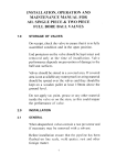
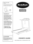
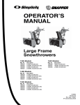
..I
~
Z
ce
:E
SNOWTHROWER
II:
Model 5210R
III
a.
o.....
II:
III
Z
Safety
•
Assembly
•
Controls
•
Operation
•
Maintenance
~
FEATURES AND CONTROLS
ENGINE IGNITION
KEYSWITCH
AUGER DRIVE --"'"\
CONTROL LEVER
\ \ \ - - - - - WHEEL DRIVE
CONTROL LEVER
~~--------- DISCHARGE CHUTE
CONTROL CRANK
i l - - - - - - DEFLECTOR CHUTE
SHIFT HANDLE ---~-~
CAP
, - - - - - - DEFLECTOR CHUTE
t::.-
CHUTE GUARD
IMPELLER - - - - - -.......
(INSIDE HOUSING)
SKID SHOE - - - - - - - -
" - - - - ADJUSTABLE SCRAPER
BLADE
AUGER
TABLE OF CONTENTS
Page
SECTION 1: Safety
Training
Preparation
Operation
Maintenance and Storage
Decals
SECTION 2: Easy Assembly
SECTION 3: Snowthrower and
Engine Controls
Snowthrower Controls
Auger Drive Control Lever
Wheel Drive Control Lever
Discharge Chute Control Crank
Discharge Chute Deflector Cap
Shift Handle
Skid Shoes
Scraper Blade
Engine Controls
Engine Ignition Keyswitch
Engine Control Lever
Engine Choke Knob
Pre-Starting Primer Button
Engine Recoil Starter
Fuel Shutoff Valve
120V Electric Starter (Optional)
4
4
4
5
6
6
Page
SECTION 4: Operation
14
Pre-Start Checklist
14
Starting
14
Stopping
16
Moving the Snowthrower in Reverse . . 16
Changing Speeds
17
Snowthrowing Tips
17
7
SECTION 5: Engine and
Snowthrower
Maintenance
11
11
11
11
11
11
11
12
12
12
12
13
13
13
13
13
13
19
19
Engine Maintenance
Checking Engine Oil Level and
Adding Oil to Engine
19
Changing the Engine Oil
19
Engine Ignition System
20
Spark Plug
20
Carburetor Adjustment
20
Snowthrower Maintenance
20
Lubrication
20
Wheel Drive Cable Adjustment
21
Wheel Drive Belt Removal and
Installation
21
Auger Drive Cable Adjustment
22
Auger Drive Belt Removal and
Installation
23
Maintenance Schedule
24
Troubleshooting
25
Specifications
Inside Back Cover
1
Dear TROY-SILT Snowthrower™ Owner:
Congratulations! You now own one of the finest snowthrowers available today.
To help you safely and efficiently assemble, operate, and service your snowthrower, we've
prepared this Owner/Operator Manual for you. This Manual gives you important information you
need to safely operate and service your snowthrower.
Sefore assembling your new snowthrower, please read "Section 2: Easy Assembly" all the
way through. These assembly instructions will tell you how to assemble your new snowthrower
with a minimum of tools, time, and fuss.
Sefore starting or operating the snowthrower, read "Section 1: Safety", "Section 3: Snow
Thrower and Engine Controls", and "Section 4: Operation". Make sure that you know how to
safely operate the snowthrower. If you lend the snowthrower to another person, be sure he or
she reads, understands, and follows the safety and operating instructions given in this Manual.
Of course, if you should have any questions about your snowthrower, we are never farther
away than your telephone. Our telephone numbers and business hours are on Page 3 and on
the back cover of this Manual.
If you should ever need replacement parts for your snowthrower, you can either stop by your
local dealer or order the part directly from us.
Please remember, we are here to help you.
TROY-SILT Manufacturing Company
This TROY-BILT Snowthrower™ has passed
the safety standards of the Outdoor Power
Equipment Institute and an individual testing
laboratory.
2
FOR SERVICE OR PARTS
For service questions, operating questions, or
replacement parts, you can either contact us at the
factory or see your local servicing dealer. Our factory
ADDRESS
addresses, hours, and telephone numbers are listed
below for your convenience.
TELEPHONE NUMBERS
HOURS
In the U.S.A.
TROY-BILT MFG. CO.
102nd St. & 9th Ave.
Troy, NY 12180
M-F 8 a.m. to 7 p.m.
Sat. 9 a.m. to 4 p.m.
(Toll-free) 1-800-833-6990
M-F 8 a.m. to 5 p.m.
Local (416 area code): 624-8423
From Ontario & Quebec: (Toll-free) 1-800-387-3351
From western Canada & the Maritime Provinces:
(Toll-free) 1-800-387-3316
In Canada
GARDEN WAY CANADA, INC.
1515 Matheson Blvd., Unit B11
Mississauga, Ontario L4W 2P5
When you contact the factory or local servicing
dealer for parts or service information, please provide
the following information:
Snowthrower Serial Number:
(See Figure at right)
Snowthrower Model
Number:
_
_
Date of Delivery:
_
Engine Manufacturer:
_
Engine Modell
Serial Number·:
_
!
SERIAL NUMBER AND
MODEL NUMBER DECAL
• For the location of the engine model! serial number,
please refer to the engine owner's manual which
was included in the literature package.
IMPORTANT
All references to left, right, front, and rear in this Manual
are determined from the operator's position - standing
behind the handlebars and facing the direction of forward travel.
3
SECTION 1: SAFETY
IMPORTANT
Safe Practices for Walk-Behind Snowthrowers.
This is a safety alert symbol. It is
used in this Manual and on snowthrower decals to alert you to potential hazards. Whenever you see this
TRAINING
1. Very carefully read this Owner/Operator Manual
and any other literature you receive. Be
thoroughly familiar with the controls and proper
use of the equipment. Know how to stop the
snowthrower and disengage its controls quickly.
2. Never allow children to operate the snowthrower.
Never allow uninstructed or irresponsible adults
to operate the snowthrower.
3. Keep the area of operation clear of all persons,
particularly small children, and pets.
PREPARATION
1. Thoroughly inspect the area where the snowthrower will be used. Remove all doormats,
sleds, boards, wires, and other foreign objects.
snowthrower is indoors or when the engine is
running or hot. Allow the engine to cool for several minutes before filling the gas tank. Use an
approved fuel container. Use a funnel or spout to
prevent spillage. After filling, securely reinstall
the gas tank and fuel container caps. Wipe up
any spilled gasoline before starting the engine.
11. Do not fill the gas tank all the way up to the top
of the filler neck. Fill the tank up only to within
112-inch of the bottom of the filler neck.
12. Before starting the engine, check the auger and
discharge chute to make sure that they are free
of ice.
13. Do not operate the snowthrower without guards
or safety devices in place. Do not attempt to
defeat the purpose of these safety devices.
2. Disengage all clutches and shift into neutral
before starting the engine.
14. Before starting the engine, check the snowthrower for loose or missing fasteners (nuts, screws, &
bolts).
3. Do not operate the snowthrower without wearing
adequate winter outer garments. Wear footwear
that will improve footing on slippery surfaces.
15. Keep smoking materials, sparks, and flame away
from the gas tank and fuel container.
16. For electric starting snowthrowers:
4. Handle gasoline with care; it is highly flammable
and its vapors are explosive.
5. Adjust the collector housing height to clear gravel
or crushed rock surfaces.
6. Never attempt to make any adjustments while
the snowthrower is running (unless otherwise
specified in this Manual).
7. Let the engine and snowthrower adjust to outdoor temperatures before starting to clear snow.
8. Always wear safety glasses or eye shields during
operation or while performing an adjustment or
repair to protect your eyes from objects that may
be thrown from the machine.
9. Check the engine oil level before starting the
engine.
10. Check the gas level in the gas tank before starting the engine. Don't fill the gas tank when the
4
symbol, read and obey the safety
message that follows it. Failure to obey
the safety message could result in
personal injury or property damage.
A. Use a 3-pronged properly rated and approved
electrical cord. Make sure that you plug this
electrical cord into a properly grounded
3-pronged outlet.
B. Before use, inspect the electrical cord to
make sure that it is not damaged.
C. When connecting or disconnecting the electrical cord, stand on dry ground - do not stand
in puddles or on wet ground. Make sure that
your hands (or gloves) are not wet. Do not use
the electric starter if it is raining.
D. When connecting the electrical cord, first
connect the cord to the electric starting switchbox
(on top of the engine). Then connect the electrical cord to a properly grounded 120V wall outlet.
This will help prevent any sparks from occurring
near the engine.
SAFETY
To prevent a shock hazard, use the electric
starting system only with an electrical cord rated
for outdoor use. Be sure this electrical cord is of
a sufficient gauge.
F. Do not abuse the electrical cord. Never pull
the snowthrower by the cord. Never yank the
cord to disconnect it from the outlet. Keep the
cord away from oil, sharp edges, and excessive
heat.
OPERATION
1. Before each use, check the operation of the
snowthrower's controls. Do not operate the
snowthrower unless all controls are functioning
properly.
2. Do not put hands or feet near or under rotating
parts. Keep clear of the intake and discharge
openings at all times.
3. Exercise extreme caution when operating or
crossing gravel drives, walks, or roads. Stay alert
for hidden hazards or traffic.
4. After striking a foreign object, stop the engine,
disconnect the spark plug wire from the spark
plug, and thoroughly inspect the snowthrower for
any damage. Repair any damage before restarting and operating the snowthrower.
5. If the snowthrower should start to vibrate abnormally, stop the engine, disconnect the spark plug
wire and check immediately for the cause. Vibration is generally a warning of trouble.
6. Stop the engine and disconnect the spark plug
wire whenever you leave the operating position,
before unclogging the auger/impeller housing or
discharge chute, and when making any repairs,
adjustments, or inspections.
7. When clearing, repairing, or inspecting, make
sure that the auger /impeller and all other moving parts have stopped. Stop the engine, disconnect the spark plug wire and keep it away from
the spark plug to prevent accidental starting.
8. Do not run the engine indoors, except when
starting the engine and transporting the snowthrower into or out of the building. Open the
buillding's outside doors - exhaust fumes contain carbon monoxide, a deadly poison that is
odorless and colorless.
9. Do not clear snow across the face of slopes.
Exercise extreme caution when changing direction on slopes. Do not attempt to clean steep
slopes.
10. Never operate the snowthrower without proper
guards, plates, or other safety protective devices
in place.
11. Never operate the snowthrower near buildings,
glass enclosures, automobiles, window wells,
drop-offs, etc. without proper adjustment of the
snow discharge angle and direction. Keep children and pets away.
12. Do not overload the snowthrower capacity by
attempting to clear snow at too fast a rate.
13. Never operate the machine at high transport
speeds on slippery surfaces. Look behind and
use care when backing.
14. Never direct discharge at bystanders. Never
allow anyone in front of the snowthrower.
15. Disengage power to the auger when the snowthrower is transported or not in use.
16. Use only attachments and accessories that are
recommended by Troy-Bilt Manufacturing
Company.
17. Never operate the snowthrower without good
visibility or light. Always be sure of your footing
and keep a firm hold on the handles. Walk never run.
18. If the auger /impeller or discharge chute should
clog with snow, NEVER use your hands or feet to
remove the snow. Shut the engine off and disconnect the spark plug wire. Then use a long
stick (at least 3-feet long) to clear the blockage.
19. Do not change the engine governor setting or
overspeed the engine.
20. Stop both the wheel drive and the auger drive if
you are approached by any child, inattentive
adult, or pet.
21. Do not touch engine parts which may be hot
from operation. Allow the engine to cool before
inspecting, cleaning, or repairing it.
22. If you have to pull the snowthrower rearward,
release both handlebar levers. Always check
behind you for hazards.
23. Do not operate the snowthrower while under the
influence of alcohol or drugs.
24. Never attempt to carry children on the snowthrower. They could fall off and be seriously
injured or they could interfere with the safe operation of the snowthrower.
25. Use extra care when using the snowthrower near
blind corners, shrubs, trees, and any other objects
that may obscure vision.
26. Keep children out of the area of operation. Keep
children under the watchful eye of an adult other
than the person operating the snowthrower.
Never assume that children will remain where
you last saw them.
5
SAFETY
27. Do not use the snowthrower near drop-ofts, ditches,
or embankments. If the snowthrower's wheel
should go over the edge, or if the edge would cave
in, the snowthrower could suddenly overturn.
6. Run the snowthrower a few minutes after you've
finished throwing snow to prevent freeze-up of
the auger. Brush off snow build-up on the
snowthrower.
28. Do not wear loose clothing such as scarves that
could get caught in the rotating parts of the
snowthrower.
29. Exercise caution to avoid slipping or falling,
especially when operating in (R) Reverse.
7. Remember, the end of the winter is a good time
to inspect your snowthrower and order any
replacement parts.
8. Use only genuine Troy-Bilt replacement parts.
Replacement parts manufactured by others
could present safety hazards even though they
may fit on this snowthrower.
MAINTENANCE AND STORAGE
1. Never perform any maintenance while the
engine is running or when the spark plug wire is
connected to the spark plug, except when specifically instructed to do so in this Manual.
9. Store gasoline in a cool, well-ventilated area,
safely away from any sparks or flame producing
equipment. Store gasoline in an approved container, safely out of the reach of children.
2. Check shear bolts and other fasteners at frequent intervals for proper tightness to be sure
the snowthrower is in safe working condition.
10. Touch up scratches, unpainted or rusted areas
with paint.
3. Never store the snowthrower with gas in its gas
tank inside a building where ignition sources
(such as hot water heaters, space heaters,
clothes dryers, etc.) are present. Allow the
engine to cool before storing the snowthrower in
any enclosure.
DECALS
4. Refer to "Storage" in this Manual and to the
Engine Owner's Manual for important details if
the snowthrower is to be stored for an extended
period.
5. Maintain or replace safety and instructional
labels as necessary. (See the Snowthrower Parts
Catalog for location of labels.)
6
For your personal safety and the safety of others, a
number of safety message decals have been affixed
to your snowthrower. Keep them clean and legible at
all times. Contact your local servicing dealer or the
factory for replacements if any of these decals is
missing or becomes illegible.
Refer to the separate Snowthrower Parts Catalog
for decal locations, part numbers, and ordering
instructions.
SECTION 2: EASY ASSEMBLY
Before you begin assembly, read this Section
all the way through to familiarize yourself
with the assembly steps. Then gather the
tools you'll need.
To assemble your snowthrower, you'll need:
1. One quart of clean, high quality engine oil. (Refer
to "Specifications" on the inside back cover for
the recommended types and viscosities.)
2. Two 7/16-inch wrenches:
3. Two 'l2-inch wrenches (one of these should be
an open-end wrench):
4. One 3/8-inch wrench.
5. A small amount of multipurpose automotive
grease.
6. One 5/16-inch wrench.*
7. One automotive-type tire pressure gauge.
8. One 9/16-inch wrench.*
9. A clean funnel.
10. A hammer and block of wood to tap the roll pin
into the plastic universal joint.
*You can substitute adjustable wrench(es).
Compare the parts you received in the shipping
carton with the list below to make sure you received
everything. If you are missing any parts, please contact your local servicing dealer or call the factory for
replacements.
Your shipping carton should contain:
1. The snowthrowerlenginelauger assembly.
2. The handlebar assembly.
3. The discharge chute assembly.
4. The hardware package, which consists of:
A. One roll pin.
B. Two #10-24 x 7/8 hex screws.
C. Two #10 flat washers.
D. Two #10-24 locknuts.
E. Two ignition keys.
F. One tie strap.
G. Two cable brackets.
H. Six locknuts, 5/16-18.
I. Two spacers.
J. Two extra 5/16-18 shear bolts (for auger).
K. Four 5/16-18 x 3/4 hex flange screws.
7
EASY ASSEMBLY
)
B~
Figure 2-1
Step 1: Attach the Handlebars.
1. Remove the four loosely installed 5/16-18 x 7/8
flange screws from holes A.
2. Place the lower ends of the handlebar assembly
on the outside of the upper rear corner of the
frame as shown in Figure 2-1 (Item A). Align the
two holes in the left side of the lower end of the
handlebars with the two holes in the left side of
the frame.
3. Loosely install a 5/16-18 x 3/4 hex flange screw
into each of these holes.
4. Repeat the previous two steps for the right side of
the lower handlebars.
5. Evenly tighten all four screws.
6. Use the two 7/16-inch wrenches to check the four
handlebar control panel mounting screws (Figure
2-1, Item CC) for tightness.
Step 2: Connect the Ignition Ground
Wires
1. Run the black ignition ground wire down the lefthand handlebar tube as shown in Figure 2-1 and
2-2 (Item B).
2. Plug the connector at the lower end of the black
ignition ground wire into the terminal beneath the
Engine Control Lever. See Figure 2-1 (Item B).
3. Attach the black ground wire
to the lower left handlebar
with the two tie straps. See
Figure 2-1 and 2-2 (Item C).
N
Figure 2-2
8
EASY ASSEMBLY
Step 3: Attach the Deflector Chute
Assembly.
1. Use a 3/8-inch
wrench and a
5/16-inch wrench to
remove two of the
three sets of shims
and clips (Figure
2-3, Items D & E)
from the lower, rear
part of the deflector
chute assembly.
Don't remove the
shim and clip that is
in front of the chute
opening.
2. Apply multipurpose automotive grease all around
the surface of the deflector chute flange (Figure
2-3, Item F).
3. Place the deflector chute onto the flange as
shown in Figure 2-3.
4. Reinstall the two sets of shims and clips you
previously removed. Make sure that the shims
(Figure 2-3, Item D) are above the deflector chute
flange (Figure 2-3, Item F).
5. Connect the chute crank (Figure 2-1, Item G) to the
plastic universal joint (Figure 2-1, Item H) by using
the hammer and block of wood to gently tap the
roll pin into the universal joint and chute crank.
6. Move the discharge chute deflector cap (Fig. 2-3)
upward.
7. Rotate the chute control crank at the handlebar
console to make sure that the deflector chute
turns without binding. If the deflector chute binds,
readjust bracket (Figure 2-1, Item J) as follows:
A. Loosen screw (Figure 2-1, Item K).
B. Adjust bracket (Figure 2-1, Item J) by moving it
inward or outward as necessary.
C. Retighten screw (Figure 2-1, Item K).
D. Repeat Step 7.
Step 4: Attach Cables to Control
Levers.
1. Place one of the hex screws (Figure 2-1, Item L)
through the hole in the right-hand handlebar lever.
Hold the screw in place and put a spacer (Figure
2-1, Item M) over the threaded end of the hex
screw. Run the auger drive cable from the righthand side of the snowthrower, upward beneath
the handlebar control panel, and place the upper
end of the cable over the spacer.
4. Attach the cable brackets to the lower inner side
of the handlebar tubes as follows:
A. Remove a 114-20 x 3/4 screw from the inside
bottom of the handlebar and insert it into one of
the cable brackets (Figure 2-2, Item AA).
B. Place the legs of the bracket and screw on the
lower inside of the handlebar tube. See Figure
2-2. Use a 3/8-inch wrench to securely tighten the
screw. Make sure that the bracket is positioned as
shown in Figure 2-2 - with the horizontal leg of
the bracket above the screw head.
C. Repeat Steps 4-A and 4-B for the remaining
bracket and screw.
5. Secure the adjustment section (Figure 2-2, Item N)
of the cable to the cable bracket as follows:
A. Pull downward on the cable and insert the
adjustment section of the cable into the slot in the
cable bracket. The horizontal leg of the cable
bracket should fit between the two nuts that are
on the threaded portion of the cable's adjustment
section.
B. Loosely tighten the adjustment section's two
nuts to prevent the cable from pulling free of the
adjustment section. You'll tighten these nuts later,
after you've checked the cable tension.
C. Repeat Steps 5-A and 5-B for the remaining
cable bracket and cable.
6. Check the tautness of the cables. The cables
should just barely be taut when the handlebar
levers are not engaged. If the cables have to be
adjusted, proceed as follows.
A. Unscrew the upper nut on the adjustment section several turns.
B. If the cable tension is too loose, screw the
lower adjustment section nut counterclockwise (as
viewed from above) until the cable is taut.
If the cable is too taut, screw the lower adjustment section nut clockwise (as viewed from
above) until the cable is just taut.
C. Use a 112-inch open-end wrench to hold the
lower nut in place. Screw the upper nut clockwise
until it touches the cable bracket. Use another
112-inch open end wrench to securely tighten the
adjustment section's upper nut tight against the
cable bracket.
D. Again check the tension of the cable to make
sure that the tightening procedure did not upset
the cable's adjustment.
2. Place a flat washer and nut onto the threaded end
of the hex screw. Use a 5/16-inch and a 3/8-inch
wrench to securely tighten the nut and hex screw.
3. Repeat Steps 4-1 and 4-2 for the left-hand handlebar lever and wheel drive cable.
9
EASY ASSEMBLY
Step 5: Check the Tires' Air Pressure.
1. Use an automotive-type tire pressure gauge to
check the air pressure in the tires.
2. Make sure that both tires are evenly inflated - or
else the snowthrower could pull to one side. The
correct tire pressure is 15 to 20 PSI (Pounds per
Square Inch).
Step 6: Add Oil to the Engine.
1. Unscrew the dipstick/oil filler cap (Figure 2-1,
Item 0).
2. Insert a clean funnel into the oil filler tube.
3. Slowly pour engine oil into the oil fill tube. The engine
should hold approximately 21 ounces of oil. While
pouring, pause frequently to check the oil level by
reinstalling the dipstick (firmly screw it in place),
and then removing it. Don't over-fill the engine
with oil - stop adding oil when it reaches the "F"
mark on the dipstick.
Step 7: Check the 'n'ansmission Gear
Oil Level.
Although we filled your snowthrower's transmission
with the correct SAE 90 weight gear oil at the factory,
be sure to double-check the gear oil's level. Please
refer to "Lubrication" on Page 20 of this Manual for
instructions.
Step 8: Attach the drift slicers to the
snowthrower's auger housing.
Use four 5/16-18 x 3/4 flange screws and lock
nuts to secure the drift slicers to the outside of the
snowthrower's auger housing. Use bolt holes (Figure
2-1, Item SS) when attaching the drift slicers.
You've now finished assembling your snowthrower.
Please read "Section 1: Safety", "Section 3: Controls",
and "Section 4: Operation" before you start the
snowthrower's engine.
Note: Store the two extra shear bolts and nuts in an
easily remembered location. If an auger shaft bolt
should break, simply replace it with one of these bolts.
10
SECTION 3: SNOW THROWER AND
ENGINE CONTROLS
This Section describes the location and function of
the various controls you will need to use when operating the snowthrower. For complete step-by-step
operating instructions, please refer to "Section 4:
Operation".
SNOW THROWER CONTROLS
trol crank to move the discharge chute from full left to
full right.
When throwing snow, turn the discharge chute so
that it throws the snow downwind (as long as downwind is in a safe direction).
When you begin a turn (while throwing snow),
remember to move the discharge chute so that the
snow is always being discharged downwind.
A
c
Figure 3-1
Auger Drive Control Lever
(Figure 3-1, Item A)
Discharge Chute Deflector Cap
(Figure 3-2, Item D)
This lever is located on the top of the right-hand
handlebar tube in front of the grip. It is used to
engage and disengage drive to the auger.
Moving this lever down and holding it against the
handlebar will make the auger rotate. To stop the auger,
simply release the lever.
This control is used to direct the vertical angle of
snow discharge. This angle is adjusted by moving the
lever on the side of the deflector cap outward, moving the deflector cap up or down as required, and
then releasing the lever.
Usually keep the angle of snow discharge low
(especially in windy conditions).
Wheel Drive Control Lever
(Figure 3-1, Item B)
This lever is located on the top of the left-hand
handlebar tube in front of the grip. It is used to
engage or disengage drive to the wheels.
Moving this lever down and holding it against the
handlebar will make the wheels turn [when the shift
handle is not in (N) Neutral]. To stop the wheels from
turning, simply release the lever.
Discharge Chute Control Crank
(Figure 3-1, Item C)
The discharge chute control crank is located on the
left-hand side of the rear lip of the handlebar control
panel.
Turning the discharge chute control crank clockwise will turn the discharge chute to the right. Turning
the discharge chute control crank counterclockwise
will turn the discharge chute to the left. It will take
approximately 8'/2 turns of the discharge chute con-
Shift Handle (Figure 3-3, Item DO)
The shift handle is located on the right-hand side
of the rear of the chassis. It is used to select one of
three forward speeds [(3) High, (2) Medium, or (1)
Low], (N) Neutral, or (R) Reverse. In the (N) Neutral
position, the wheels are free to turn and you can easily push the snowthrower. However, you can push the
11
SNOW THROWER AND ENGINE CONTROLS
snowthrower when the shift handle is in any of the
forward or reverse gears. It will take increased effort
because you are also turning the wheel drive system
by way of the wheels.
When the top of the shift handle is moved all the
way to the right, the snowthrower will be in (R)
Reverse. When the top of the shift handle is moved
all the way to the left, the snowthrower will be in (3)
High speed. There is a detent (a stop) for each of the
speeds between (R) Reverse and (3) High speed. As
you slowly move the shift handle sideways, you can
feel these detents.
These speeds refer only to the wheel speed, not
the auger speed.
To use the shift handle, release the wheel drive
handlebar control lever. Allow all forward (or reverse)
motion of the snowthrower to stop. Move the shift
handle into the desired speed and re-engage the
wheel drive handlebar control lever.
When familiarizing yourself with the various
speeds, or when moving the snowthrower near
obstacles, use (1) Low or (2) Medium speed.
Auger is shown upside-down
SCRAPER
BLADE
--r-r--_...,
SKID
SHOES
Figure 3-4
Skid Shoes (Figure 3-4)
A skid shoe is located at the bottom of each side of
the auger housing. These skid shoes are used to
raise or lower the height of the auger housing.
This allows you to lower the auger housing when
throwing snow off smooth surfaces so you can get a
cleaner path. If you're throwing snow from clear, level
ground, adjust the skid shoes so that the scraper
blade clears the ground by approximately 1/8-inch.
When throwing snow from rough surfaces (such as
those covered by gravel), the skid shoes allow you to
raise the auger housing so that the scraper blade
clears the gravel and doesn't pick it up and throw it. If
you're throwing snow from a gravel covered area,
adjust the skid shoes so that the scraper is above the
gravel.
12
To adjust the skid shoes:
1. Move the snowthrower to a level area.
2. Shut the snowthrower's engine off. Disconnect
the spark plug wire and prevent it from touching
the spark plug
3. Use a 9/16-inch wrench to loosen the two bolts
that secure the skid shoe to the side of the
auger housing.
4. Move the skid shoe up or down as necessary to
obtain the desired gap between the scraper
blade and the ground.
5. Repeat Steps 3 and 4 for the other skid shoe.
Be sure to adjust this skid shoe the same
amount or else you'll get a sloping cut when
you throw snow.
Scraper Blade (Figure 3-4)
The scraper blade is located at the lower rear of
the auger housing. It is attached to the auger housing by 5 bolts and nuts. The scraper blade is adjustable for height and is replaceable (in case it becomes
worn out or damaged).
Since the scraper blade will contact the ground, it
will gradually wear and will be subject to damage. At
the beginning and end of each season, check the
scraper blade for excessive wear and damage.
You can adjust the scraper blade by loosening the
5 nuts that attach it to the auger housing. The nuts
are located in the lower inner surface of the auger
housing. When all the nuts are loose, move the
scraper blade up or down as necessary. Hold the
scraper blade in this position and re-tighten the nuts.
ENGINE CONTROLS
Engine Ignition Keyswitch
(Figure 3-1, Item E)
The keyswitch is located in the center of the lip on
the rear of the handlebar control panel.
There are two positions of this keyswitch: RUN and
STOP.
Turning the key to the RUN position allows you to
start the engine with the recoil starter or optional
electric starting motor. Turning the key to STOP will
shut the engine off.
Always remove the engine ignition key when storing,
cleaning, or performing any maintenance on the
snowthrower.
SNOW THROWER AND ENGINE CONTROLS
Engine Recoil Starter (Figure 3-5, Item I)
The recoil starter is located on the rear of the
engine. It is used to "pull-start" the engine.
To use the recoil starter, slowly pull the recoil starter's
black plastic handle until you feel some resistance
from engine compression. Look behind you to make
sure there are no obstacles in the way, and then rapidly
pull the handle. Allow the rope to slowly be pulled
back into the recoil starter mechanism. Repeat as
necessary until the engine starts.
G
Figure 3-5
F
Engine Control Lever (Figure 3-5, Item F)
This lever is located on the rear of the left-hand
side of the engine.
It is used to increase or decrease the engine
speed. This lever also will effect the speed of the
wheels and auger when those handlebar control
levers are engaged.
Moving the engine control lever upward increases
engine speed. Moving the levE:r downward decreases
engine speed.
Engine Choke Knob (Figure 3-5, Item G)
The engine choke knob is located on the left rear
side of the engine on the carburetor's heat box. The
choke knob is used to enrich the gasoline mixture
when starting. This makes starting easier when the
engine is cold.
Before starting a cold engine, rotate the choke
knob clockwise to its FULL CHOKE position. After
the engine starts, gradually rotate the choke knob
counterclockwise to its CHOKE OFF position.
If the engine is still warm from a previous run, you
may not have to move the choke knob all the way to
its FULL CHOKE position. You may only have to
move the choke knob to a partial choke postion
between CHOKE OFF and FULL CHOKE positions.
Or you may not have to move the choke knob away
from its CHOKE OFF position.
Pre-Starting Primer Button
(Figure 3-5, Item H)
The pre-starting primer button is located on the
upper left-hand side of the rear of the engine.
Pressing this button pumps small amounts of gasoline into the engine to improve cold weather starting.
Make sure that your finger covers the small hole in
the center of the button when you press it.
Figure 3-6
Fuel Shutoff Valve (Figure 3-6)
The fuel shutoff valve is located beneath the gas
tank. It is located in the fuel line between the gas
tank and the carburetor. Turning the fuel shutoff valve
clockwise will shut off the fuel flow to the carburetor.
Turning the fuel shutoff valve counterclockwise will
allow fuel to flow between the gas tank and the
carburetor.
After shutting the engine off, turn the fuel shutoff
valve off. Before starting, make sure that you turn the
fuel shutoff valve on, or else the engine will stop and
you will not be able to re-start it until you turn the fuel
shutoff valve back on.
120V Electric Starter (Optional)
The 120V electric starter switch is mounted on top
of the engine.
To function, the electric starter must first be connected to a 120V wall outlet. After this connection is
made, you simply push the starter button (on top of
the electric starter switch) to start the engine. As soon
as the engine starts, release the starter button.
The electric starter is thermally protected. If overheated, it will automatically stop. Allow the starter to
cool before attempting to use the electric starter.
Be sure to review the operating instructions that
come with the electric start kit.
13
SECTION 4: OPERATION
Pre-start Checklist:
(Snowthrower viewed upside down)
1. Review" Section 1: Safety" and" Section 3:
Controls' '.
2. Check the snowthrower for any loose or missing
hardware.
3. Check the engine oil level.
4. Check the level of the gas in the gas tank.
5. Check the skid shoe (Figure 4-1, Item A) adjustment. See "Skid Shoes" in Section 3.
6. Check the scraper blade (Figure 4-1, Item B) for
wear and adjustment.
Figure 4-1
7. Check the discharge chute crank (Figure 3-1,
Item C) for freedom of movement. Then adjust
the discharge chute and deflector cap (Figure
4-2, Item C) to the desired direction and angle of
discharge.
8. Make sure that the chute guard (Figure 4-2, Item
D) is installed.
9. Check the handlebar control levers (Figure 3-1,
Items A & B) for freedom of movement.
10. Check the tire pressure. Make sure both tires are
inflated equally. Correct tire pressure is 15 to 20
PSI.
HINT: To help prevent snow from sticking to the inside
of the deflector, discharge chute, and auger-impeller
housing, spray these areas with a silicone spray.
Figure 4-2
Starting
1. Fill the snowthrower's gas tank as follows:
A,DANGER Gasoline is highly flammable and its vapors are explosive.
• Never fill gas tank when engine is running or
still hot from operation. Allow engine and muffler to cool at least 2 minutes before refueling.
• Do not allow open flames, sparks, matches, or
smoking in the area.
• Fill fuel tank outdoors in a well-ventilated area.
• Wipe up any spills and move the snowthrower
away from gasoline fumes before starting the
engine.
• Use only an approved gasoline container.
Store it safely out of the reach of children.
14
• Store gasoline in a well-ventilated area. Do
not store where vapors may reach an open
flame or spark, or where ignition sources
(such as a hot water heater or space heater,
furnaces, clothes dryers, stoves, electric
motors, etc.) are present.
• Never refuel the gas tank when the electrical
cord is connected to the snowthrower (on
electric start models).
Failure to follow these instructions could
result in personal injury or property damage.
OPERATION
A. Unscrew the gas tank cap from the
engine's gas tank.
B. Insert a clean funnel into the gas tank (or
use a fuel container that has a flexible pour
spout).
C. Pour the gas into the tank. Don't fill the
tank all the way. Leave approximately 1f4-inch
of air space between the top of the fuel and
the bottom of the gas tank's filler neck.
D. Wipe up any spilled gas. Securely reinstall
the gas tank cap.
2. Move the shift handle (Figure 3-3, Item D) to its
Neutral position (N).
3. Turn the engine ignition key (Figure 3-1, Item E)
to its RUN position.
4. Move the choke knob (Figure 3-4, Item G) to its
FULL CHOKE position if the engine is cold - or
to a partial choke position if the engine is warm
from a previous run.
5. Push the pre-starting primer button (Figure 3-4,
Item H) two or three times. Omit this step if you are
using the 120V electric starter. If the engine is
still warm from a previous run, push the pre-start
primer button one time only. If the temperature is
below 15°F, you may have to push the prestarting primer button more than three times.
6. Move the engine control lever to its FAST
position.
7. Make sure that both handlebar levers (Auger
Drive and Wheel Drive) are released.
WARNING Engine exhaust contains
carbon monoxide, an odorless and
deadly poison. Do not run the engine
indoors or in a poorly ventilated area.
Failure to follow this instruction could
result in personal injury.
8. To start the engine with the recoil starter:
A. Grasp the black plastic handle of the recoil
starter rope (Figure 3-5, Item I). Look behind you
to make sure there are no obstacles in the way.
Place your other hand on the right-hand handlebar to stabilize the snowthrower when you pull
the recoil starter rope.
B. Pull the recoil starter rope handle out slowly
until you feel some resistance from engine
compression.
C. Then pull the handle rapidly. Allow the starter rope to rewind slowly. Repeat as necessary
until the engine starts.
D. Gradually move the choke knob to its NO
CHOKE position and allow the engine to warm up.
9. To start the engine with the (optional) 120V
electric starter:
WARNING To prevent personal injury
from electrical shocks:
• Do not use the 120V electric starter
in the rain.
• Do not stand in puddles or on damp
ground when using the electric starter or
when connecting the electrical cord.
A. Plug the electrical cord into the switchbox on
top of the engine.
B. Plug the other end of the electrical cord into
a properly grounded 120V wall outlet.
C. Push the starter button on top of the switchbox. As soon as the engine starts, release the
button.
D. Gradually move the choke knob to its NO
CHOKE position and allow the engine to warm up.
E. After the engine is warmed up, unplug the
electrical cord from the 120V wall outlet. Then
unplug the electrical cord from the switchbox on
top of the engine.
10. Check operation of the Auger Drive Lever as
follows:
A. Quickly squeeze and release the Auger Drive
Lever.
B. The auger should begin spinning when you
squeeze the lever. It should stop spinning when
you release the lever.
WARNING If the auger spins before
you squeeze the Auger Drive Lever, or
if the auger continues to spin after you
release the Auger Drive Lever, do not
use the snowthrower. Shut the snowthrower's engine off, disconnect the
spark plug wire and prevent it from
touching the spark plug. Adjust or
repair the auger drive mechanism.
See "Auger Drive Cable Adjustment' '.
Failure to follow this instruction could
result in personal injury or property
damage.
11. Check the operation of the Wheel Drive Lever as
follows:
15
OPERATION
A. Move the shift handle to its LOW position.
B. Quickly squeeze and release the Wheel
Drive Lever.
C. The wheels should begin turning when you
squeeze the lever. They should stop turning
when you release the lever.
WARNING If the wheels turn before
you squeeze the Wheel Drive Lever, or
if the wheels continue to turn after you
release the Wheel Drive Lever, do not
use the snowthrower. Shut the snowthrower's engine off, disconnect the
spark plug wire and prevent it from
touching the spark plug. Adjust or
repair the Wheel Drive Mechanism.
See "Wheel Drive Cable Adjustment."
Failure to follow this instruction could
result in personal injury or property
damage.
12. Move the shift handle into the desired speed
range. (You do not have to start in 1-LOW. See
"Changing Speeds.")
13. If both handlebar levers operate properly, reengage the levers and begin operation.
NOTE: If you only want to move the snowthrower (but
not throw snow), simply engage the Wheel Drive
Lever. Leave the Auger Drive Lever disengaged
(released).
B. While engine is running, push the starter
button and spin the engine's starter for several
seconds - the unusual sound made by the
spinning starter won't harm the engine or starter.
C. Disconnect the electrical cord from the 120V
wall outlet. Then disconnect the electrical cord
from the switchbox.
5. Turn the engine ignition key to its OFF position.
Remove key.
6. Disconnect the spark plug wire and prevent it
from touching the spark plug.
7. To help avoid possible freezing of the controls:
A. Wipe all snow and moisture from the engine
in the vicinity of the engine control lever and the
choke knob.
B. Move the engine control lever and the choke
knob back and forth several times.
C. Move the choke knob to FULL and leave it in
this position.
D. Move the engine control lever to the start
position and leave it there.
E. Close the fuel valve (beneath the engine's
gas tank).
Moving the Snowthrower in Reverse
1. Release both handlebar levers (Auger Drive and
Wheel Drive). If the snowthrower was moving forward, allow its forward motion to stop.
2. Move the shift handle into (R) Reverse - the top
of the shift handle will be all the way to the right.
Stopping
To quickly stop the snowthrower:
1. Release both handlebar levers.
2. Turn the engine ignition key to its OFF position.
To stop the snowthrower under normal conditions:
1. Release both handlebar levers.
2. Move the shift handle to its Neutral (N) position.
3. Move the engine control lever to its idle position.
Allow the engine to run at idle for several
minutes to melt any snow off the engine.
4. To help avoid possible freezing of starter when
snowthrower is not being used:
For standard start engines: With engine running,
pull recoil starter rope all the way out 3-4 times
- the unusual sound made by the starter rope
won't harm the engine or the starter.
For 120V electric start engines:
A. Connect electrical cord to switch box, then to
a 120V wall outlet.
16
CAUTION Before engaging the Wheel
Drive Lever when the snowthrower is in
Reverse (R), look behind you to make
sure that there are no obstacles.
Failure to follow this instruction could
result in personal injury or property
damage.
3. Slowly squeeze the Wheel Drive Lever and
guide the snowthrower rearward.
4. Before shifting into one of the forward speeds,
release the Wheel Drive Lever and let the rearward motion of the snowthrower stop.
OPERATION
Changing Speeds
You can engage the Wheel Drive Lever when the
shift handle is in any of the speeds - (R) Reverse,
(1) First, (2) Second, or (3) Third. You do not have to
begin in (1) First and then shift up through (2) Second
and then into (3) Third. You can begin in (3) Third if
you wish.
In (2) Second or (3) Third, the snowthrower will
move forward faster than in (1) First.
Before moving the shift handle to another speed,
release the handlebar levers and let the forward (or
rearward) motion of the snowthrower stop. Then
move the shift handle to the desired speed and reengage the Wheel Drive Lever.
Snow Throwing Tips
Use the pattern shown in Figure 4-3 when snow
cannot be thrown to one side of the area being
cleared. Begin throwing snow close to this side, making sure that the discharge chute directs the snow
away from this side. When you turn the snowthrower
around at the end of each pass, you'll have to gradually crank the discharge chute so that it always
throws the snow away from the area where no snow
can be thrown.
Snow is not thrown to this side.
As you turn, rotate the
discharge chute so that
snow is always thrown in
this direction.
~BEGIN
c
L~_-----.-~_ _~)
:
(
~
-
~END
.
•.. ~--:,.---------- _... ~~~
(~
SNOW IS THROWN HERE
?'
~~:::::-"""7~~:;:=:::=::...
Figure 4-3: Snow throwing pattern when snow can only be thrown to one side.
Use the pattern shown in Figure 4-4 when you wish
to throw snow to both the right and left sides of the
area being cleared. When using this pattern, you
Discharge chute direction
stays the same except
when turning.
have to change the direction of the discharge chute
only when making a turn at the end of a pass.
'---------------~ BEGIN
Snow is thrown to each
side.
Figure 4-4: Throwing snow when snow can be thrown to either side of the area being cleared.
17
OPERATION
Run the engine at full throttle when throwing snow.
Use a lower wheel speed in heavy wet snow.
Always slightly overlap each pass to make sure
that all snow is removed.
Spray the auger, inside of auger housing, inside of
discharge chute, and inside of deflector chute with
silicone spray to prevent snow from sticking to these
areas.
If possible, always try to throw snow downwind. If
you try to throw snow upwind, it could be blown back
on you, on the snowthrower, and on the area you're
clearing.
Before the first snowfall, inspect the area in which
you'll be using the snowthrower. Remove any doormats, sleds, boards, wires, and other foreign objects.
If you're throwing snow from a smooth area, adjust
the skid shoes so that the scraper blade is above the
ground by approximately 1/8-inch.
If snow should stick in the deflector chute or auger,
DO NOT use your hands or feet to dislodge it. Shut
the engine off, disconnect the spark plug wire, and
prevent it from touching the spark plug. Then use a
long stick (at least 3-feet long) to unclog thses areas.
If you're throwing snow from a gravel covered area,
adjust the skid shoes so that the scraper blade clears
the gravel.
For best results, remove snow as soon as possible
after it falls.
18
SECTION 5: ENGINE AND SNOWTHROWER
MAINTENANCE
ENGINE MAINTENANCE
Checking Engine Oil Level
and Adding Oil to Engine
Before each use, check the engine oil level. Also,
while using the snowthrower, stop the engine and
check its oil level every five hours of operation.
To check the engine oil level:
1. Shut the engine off.
2. Unscrew the dipstick (Figure 5-1, Item A). Use a
clean cloth to wipe the dipstick.
3. Re-insert the dipstick into the oil fill tube. Firmly
screw the dipstick all the way back into the oil fill
tube.
4. Unscrew the dipstick and check the oil level. It
should be between the FULL and ADD marks on
the dipstick.
Changing the Engine Oil
After the very first two hours that you operate your
snowthrower, change the engine oil. After this initial
engine oil change, change the engine oil every 25
hours of operation (or at the end of the snow throwing
season, whichever comes first).
To change the engine oil:
1. Start the engine. Allow it to warm up to operating
temperature.
2. SHUT THE ENGINE OFF.
3. Fold a piece of cardboard (approximately 3 inches
by 6 inches) lengthwise into a shallow "V". See
Figure 5-2.
A. Remove the dipstick.
4. Use a 3/8-inch open end wrench (or an adjustable
wrench) to loosen (not remove) the engine oil
drain plug (Figure 5-2, Item B).
B. Insert the clean funnel into the oil fill tube.
C. Slowly pour oil into the funnel. While pouring,
stop frequently, remove the funnel, reinstall the
dipstick, then remove it and check the oil level.
Don't overfill the engine with oil.
5. Place the folded cardboard beneath the drain
plug as shown in Figure 5-2.
6. Place a container (minimum capacity of 1 quart)
underneath the end of the cardboard to catch the
draining oil.
5. If the oil level is low, add oil as follows:
D. When the engine oil level is correct, securely
reinstall the dipstick.
Figure 5-1
Figure 5-2
19
ENGINE AND SNOWTHROWER MAINTENANCE
7. Slowly unscrew the drain plug. Allow the oil to run
down the cardboard and into the container.
8. After the oil has drained, reinstall the drain plug
and very securely tighten it.
friction points during the off-season. It will also
ensure that the snowthrower will be ready to use
when the first snow falls.
9. Add clean oil to the engine. See "Checking
Engine Oil Level and Adding Oil to Engine".
AUGER
Engine Ignition System
The snowthrower engine has an electronic ignition
system. This system eliminates the traditional set of
points and condensor. The electronic ignition system
also eliminates the yearly tune-up. The only scheduled maintenance you need to perform on the
engine's ignition system concerns the spark plug
(which is discussed next).
FRONT VIEW OF AUGER
F
Spark Plug
Yearly, or every 100 hours of operation, remove the
engine's spark plug, clean it, and inspect it. Clean
the spark plug by scraping it (don't wire brush it or
sand blast it). Replace the spark plug with a new one
if its electodes were pitted or burned, or if its porcelain was cracked.
Before installing the spark plug, set its electrode
gap at 0.030 inch.
Figure 5-4
COMPLIANCE WITH
RADIO INTERFERENCE
REGULATIONS CERTIFIED. REPLACE SPARK
PLUG WITH RESISTOR
.030 (.8 mm) SPARK PLUG.
FEELER GAUGE
Figure 5-3
Carburetor Adjustment
Your carburetor has been set for proper operation.
If you believe that it has come out of adjustment,
please refer to the engine owner's manual for the
correct carburetor adjustment procedure.
1. Use clean engine oil or a silicone spray to lubricate the handlebar levers' pivot points. Be careful
not to get any oil or silicone spray on the levers.
2. Clean any dirt off the toothed part of the flange on
the bottom of the discharge chute. Apply fresh
grease to the worm gear and toothed part of the
flange.
3. Apply fresh engine oil to the bearing on each side
of the auger shaft. Wipe off any excess oil.
4. Sparingly oil the discharge chute control crank
where it enters the control panel. Also oil it at the
support on top of the left hand rear side of the
frame.
5. Sparingly apply oil to the two pivot points on the
deflector cap.
SNOWTHROWER MAINTENANCE
Lubrication
6. One at a time, remove the wheels and apply fresh
grease to the wheel shaft and clevis pin. This
makes future wheel removal easier.
Refer to Figure 5-4 and the numbered items following it to determine which areas on your snowthrower
should be lubricated.
At the beginning and end of each snow throwing
season, be sure to lubricate the snow thrower as
recommended. This will help prevent any corrosion at
7. Check the auger gear box's gear oil level. Move
the snowthrower to a level area. Unscrew the plug
(Figure 5-4, Item 7) from the front of the gear box.
Oil should just begin to flow out of the hole. If it
doesn't, add SAE 90 gear oil to the gear box. Fill
the gear box until the oil just begins to flow from
20
ENGINE AND SNOWTHROWER MAINTENANCE
the hole. Allow any excess to drain out of the gear
box. Wipe any excess gear oil off the gear box.
Reinstall the plug.
8. Touch up any scratches, unpainted or rusty surfaces with paint.
Wheel Drive Cable Adjustment
A
CAUTION Before adjusting the wheel
drive cable, shut the engine off, allow
it to cool, disconnect the spark plug
wire and prevent it from touching the
spark plug, and remove the engine
ignition key.
Failure to do this could result in
personal injury or property damage.
R
1. Remove the two screws that secure the sides of
the belt cover (Figure 5-4, Item F) to the snowthrower. Take the belt cover off the snowthrower.
2. Push the idler pulley (Figure 5-5, Item G) to the
left until the belt (Figure 5-5, Item H) is tight.
3. Adjust the idler stop (Figure 5-5, Item I) so that
there is a gap of 3/8-inch between the left-hand
edge of the idler stop and the inner surface of the
frame. Make this adjustment by loosening the
idler screw stop nut (Figure 5-5, Item J) and sliding the idler stop right or left as needed Re-tighten
the idler stop nut when you have the 318-inch gap.
4. Check the tension on the wheel drive cable. It
should just be taut when the Wheel Drive Lever is
not engaged. If it is slack or too taut, adjust the
cable tension at the adjustment section (Figure
5-6, Item K).
5. Make sure that the spark plug wire is disconnected and not touching the spark plug. Pull the
recoil starter rope while watching the engine
wheel drive pulley (Figure 5-8, Item L). The belt
should not move on this pulley. If the belt does move,
decrease the 3/8-inch gap you set in Step 3.
6. Reinstall the belt cover (Figure 5-4, Item F) on the
snowthrower.
\~:---- G
Wheel Drive Belt Removal and
Installation
A
Figure 5-5
CAUTION Before removing or installing the wheel drive belt, shut the
engine off, allow it to cool, disconnect
the spark plug wire and prevent it
from touching the spark plug, and
remove the engine ignition key.
Failure to do this could result in
personal injury or property damage.
To remove the wheel drive belt:
1. Remove the two screws that secure the sides of
the belt cover (Figure 5-4, Item F) to the snowthrower. Take the belt cover off the snowthrower.
2. Remove the worm gear and support (Figure 5-7,
Item M) from the left
hand side of the
---------=
snowthrower by
removing the bolt
(Figure 5-7, Item N).
Figure 5-6
~M
~
N
Figure 5-7
21
ENGINE AND SNOWTHROWER MAINTENANCE
3. Remove the two (each side) flange screws (Figure
5-8, Item 0) from the snowthrower.
tighten the bolt that holds the belt guide in place.
Repeat this step for the remaining belt guide.
4. Retighten bolt that attaches belt guide (Figure 5-8,
Item S) to engine.
5. Move the rear half of the snowthrower close to the
front half. Place the auger drive belt onto the
engine auger drive pulley (Figure 5-8, Item Q).
6. Move the snowthrower halves together. Align the
four attachment holes (two in each side of the
frame). Loosely install the four screws (Figure 5-8,
Item Q) that secure the halves of the snowthrower
together. Then firmly tighten the screws.
Figure 5-8
4. Slowly pivot the rear half of the snowthrower
back. Rest the handlebars on a stable object.
5. Take the auger drive belt (Figure 5-8, Item P) off
the engine auger drive pulley (Figure 5-8, Item Q).
You may have to loosen the bolt that secures the
belt guide (Figure 5-8, Item S) to the back of the
engine and move the belt guide out of the way.
6. Loosen the bolts that attach the belt guides to the
front of the chassis below the transmission pulley.
Turn these belt guides to give you room to take
the wheel drive belt off the transmission pulley.
7. You may have to loosen the bolt that secures the
engine pulley belt guide (Figure 5-5, Item R) in
place and turn this belt guide out of the way.
7. Reinstall the worm gear and support (Figure 5-7,
Item M) to the left-hand side of the snowthrower.
Firmly tighten the bolt (Figure 5-7, Item N) that
holds it in place. Rotate the chute control crank to
make sure that the deflector chute turns freely. If it
doesn't, loosen the bolt (Figure 5-7, Item N) and
adjust the support inward or outward so that the
chute doesn't bind.
8. Adjust the wheel drive cable. See "Wheel Drive
Cable Adjustment".
9. Reinstall the belt cover on the snowthrower.
Auger Drive Cable Adjustment
CAUTION Before adjusting the auger
drive cable, shut the engine off, allow
it to cool, disconnect the spark plug
wire and prevent it from touching the
spark plug, and remove the engine
ignition key.
Failure to follow this instruction
could result in personal injury or
property damage.
8. Take the wheel drive belt off the transmission
pulley and engine wheel drive pulley.
To install the wheel drive belt:
1. Place the wheel drive belt on the engine wheel
drive pulley and transmission pulley.
2. If you had to loosen the bolt that secures the
engine pulley belt guide (Figure 5-5, Item R) in
place, position the leg of this belt guide approximately 1/16-inch from the outer surface of the
wheel drive belt and tighten the bolt that secures
it to the back of the engine.
3. Rotate one of the two belt guides that is below the
transmission pulley so that its "leg" is 1/16-inch
away from the outer surface of the wheel drive
belt. Hold the belt guide in this position and
Figure 5-9
22
ENGINE AND SNOWTHROWER MAINTENANCE
1. Remove the two screws that secure the sides of
the belt cover (Figure 5-4, Item F) to the snowthrower. Take the belt cover off the snowthrower.
To install the auger drive belt:
2. Push the idler (Figure 5-9, Item T) sideways to
tighten the auger drive belt.
2. Move one of the belt guides on the back of the
auger housing (below the auger drive pulley) so
that its "leg" is 1/16-inch away from the auger
drive belt. Hold the belt guide in this position.
Tighten the bolt that secures this belt guide to the
back of the auger housing. Repeat this step for
the remaining belt guide.
3. Look at the brake arm hole (Figure 5-9, Item U).
This hole should be flush with the outside of the
right-hand side of the frame.
4. If the brake arm hole is not flush with the outside
of the right-hand side of the frame, loosen the two
screws (Figure 5-9, Item V) and move arm (Figure
5-9, Item W) sideways as necessary. Tighten the
two screws and then repeat Steps 2 and 3.
5. Check auger drive cable tension. It should be taut
when the auger drive handle is not engaged
(when it is not squeezed down). Adjust tension at
the auger drive cable'e adjustment section (at the
lower end of the handlebar) (Figure 5-6).
Auger Drive Belt Removal and
Installation
CAUTION Before removing or installing the auger drive belt, shut the
engine off, allow it to cool, disconnect
the spark plug, and remove the
engine ignition key.
Failure to follow this instruction
could result in personal injury or
property damage.
1. Place the new auger drive belt into the groove in
the auger drive pulley.
3. Retighten the bolt that secures the belt guide
(Figure 5-9, Item S) to the engine.
4. Move the rear half of the snowthrower close to the
front half. Place the auger drive belt into the the
groove in the engine auger drive pulley.
5. Move the snowthrower halves together. Align the
four attachment bolt holes (two on each side).
Loosely intall the screws (Figure 5-9, Item X) that
secure the halves of the snowthrower together.
Firmly tighten these screws.
6. Reinstall the worm gear and support (Figure 5-7,
Item M) to the left-hand side of the snowthrower.
Firmly tighten the bolt that holds it in place. Rotate
the chute control crank to make sure that the
deflector chute turns freely. If it doesn't, loosen
the bolt (Figure 5-7, Item N) and move the support
inward or outward as necessary so that the discharge chute does not bind when you rotate the
chute control crank.
7. Adjust the Auger Drive Cable. See "Auger Drive
Cable Adjustment".
8. Reinstall the belt cover on the snowthrower.
1. Remove the two screws that secure the sides of
the belt cover (Figure 5-4, Item F) to the snowthrower. Take the belt cover off the snowthrower.
2. Remove the screw (Figure 5-7, Item N), worm gear,
and support (Figure 5-7, Item M).
3. Remove the two (each side) flange screws (Figure
5-9, Item X) from the snowthrower.
4. Slowly pivot the rear half of the snowthrower
back. Rest the handlebars on a stable object.
5. Take the auger drive belt (Figure 5-8, Item P) off
the engine auger drive pulley (Figure 5-8, Item Q).
You may have to loosen the bolt that secures the
belt guide (Figure 5-9, Item S) to the back of the
engine and move the belt guide out of the way.
6. Loosen the two belt guides that are located on the
back of the auger housing, below the auger drive
pulley. Rotate the belt guides out of the way.
7. Take the old auger drive belt off the engine pulley
and auger drive pulley.
23
ENGINE AND SNOWTHROWER MAINTENANCE
MAINTENANCE
SCHEDULE
Check engine oil level.
1/
Check all fasteners
for tightness.
1/
Check operation of Auger
Drive Lever and
Wheel Drive Lever.
1/
After
each
use
Apply oil to handlebar
control levers and
linkages.
1/
Clean all snow, slush, and
ice off snowthrower.
1/
Change engine oil.
Check tire pressure.
24
Before
each
use
Every 25 Every 50
At the
hours of
hours of end of the
operation operation
season
1/
1/
1/
Check auger gear box oil
level. Add SAE 90 gear oil
as required.
1/
Check and clean engine
cowling air screen on
engine.
1/
Check both belts for wear.
1/
Check, clean, and re-gap
(or simply replace)
spark plug.
1/
Apply a light coating of
multipurpose grease to
axle shaft bearing.
1/
Apply a light coating of oil
to drive chain.
1/
Check belts for wear and
damage.
1/
Check wheel drive belt
and auger drive belt for
adjustment.
1/
Sand and re-paint any
rusted areas.
1/
ENGINE AND SNOWTHROWER MAINTENANCE
TROUBLESHOOTING
Trouble
Engine won't start.
Engine is difficult
to start.
Engine idles rough.
Possible Problem
Solution
Ignition key in OFF position.
Turn key to ON position.
Spark plug wire
disconnected.
Reconnect spark plug wire
to spark plug.
Gas tank empty.
Fill gas tank.
Fouled spark plug.
Remove, clean, inspect, (or
replace), re-gap and
reinstall spark plug.
Engine Control Lever is in
idle position.
Move Engine Control Lever to
its FAST position.
Engine not primed enough.
Push primer button several
more times.
Engine primed too much.
Move choke knob to its OFF
position, and Engine Control
Lever to idle. Attempt to start
engine - this should burn
up excess gas in carburetor.
Then proceed with normal
starting procedure.
Fuel shutoff valve closed.
Open fuel shutoff valve.
Incorrect Choke Knob setting.
Reposition Choke Knob.
Engine Control Lever is in
incorrect position.
Move Engine Control Lever to
its FAST position.
Fuel shutoff valve closed.
Open fuel shutoff valve.
Engine not primed enough.
Push primer button several
times.
Stale gas in tank.
Drain gas. Refill with fresh gas.
Faulty spark plug.
Remove, clean, inspect, re-gap,
and reinstall spark plug.
Faulty or fouled spark plug.
Remove, clean, inspect, re-gap,
and reinstall spark plug.
Incorrect choke setting.
After engine starts, move engine
choke knob gradually to its
NO CHOKE position.
25
ENGINE AND SNOWTHROWER MAINTENANCE
TROUBLESHOOTING
Trouble
Engine overheats.
Auger drive lever does
not make auger spin.
Auger spins when Auger
Drive Lever is not
engaged.
26
Possible Problem
Solution
Dirty air screen.
Remove all debris from
air screen.
Low engine oil level.
Check engine oil level.
Add oil as necessary.
Dirty cooling fins.
Clean cooling fins.
Loose spark plug.
Disconnect spark plug wire.
Re-tighten spark plug.
Not enough tension on auger
drive belt.
Increase tension at auger drive
cable adjustment section.
Incorrect auger drive belt
adjustment.
Re-adjust auger drive cable.
Broken shear bolt(s) on
auger drive shaft(s).
Replace bolt(s).
Broken idler spring
(at lower end of cable).
Replace spring.
Broken cable.
Replace cable.
Belt guide(s) adjusted
incorrectly.
Belt guides should be 1/16-inch
away from belt.
Broken square key or loose
setscrew on auger drive pulley.
Replace key and retighten
setscrew.
Broken woodruff key and
roll pin on transmission
input shaft.
Replace woodruff key and
roll pin.
Too much tension on auger
drive cable.
Cable should just be taut when
Auger Drive Lever is not
engaged. Adjust tension at
auger drive cable adjustment
section.
Incorrect auger drive belt
adjustment.
Adjust auger drive belt.
Belt guide(s) adjusted
incorrectly.
Belt guides should be 1/16-inch
away from belt.
ENGINE AND SNOWTHROWER MAINTENANCE
TROUBLESHOOTING
Trouble
Wheel Drive Lever does
not make wheels turn.
Wheels turn when Wheel
Drive Lever is not
engaged.
Snowthrower doesn't
throw snow well.
Possible Problem
Solution
Shift Handle is in (N) Neutral.
Release Wheel Drive Lever,
move Shift Handle to desired
speed, re-engage Wheel
Drive Lever.
Not enough tension on wheel
drive belt.
Cable should just be taut when
Wheel Drive Lever is not
engaged. Adjust tension at
wheel drive cable adjustment
section.
Incorrect wheel drive belt
adjustment.
Re-adjust wheel drive belt.
Broken or excessively worn
wheel drive belt.
Replace wheel drive belt.
Broken wheel drive cable.
Replace wheel drive cable.
Broken wheel drive spring
(on end of cable).
Replace spring.
Broken square key or loose
setscrew on wheel drive pulley.
Replace key / retighten
setscrew.
Broken wheel drive chain.
Replace chain.
Broken woodruff key and/or
loose setscrew on wheel
drive pulley(s).
Replace woodruff key and
tighten setscrew.
Too much tension on wheel
drive cable.
Cable should just be taut when
Wheel Drive Lever is not
engaged. Adjust tension at
wheel drive cable adjustment
section.
Incorrect wheel drive belt
adjustment.
Re-adjust wheel drive cable.
Belt guide(s) adjusted
incorrectly.
Belt guides should be 1/16-inch
away from belt.
Discharge chute, impeller, or
auger clogged with snow, slush,
or ice.
Stop engine, disconnect spark
plug wire. Use a long stick to
unclog chute, auger, and/or
impeller.
(continued)
27
ENGINE AND SNOWTHROWER MAINTENANCE
TROUBLESHOOTING
Trouble
Snowthrower doesn't
throw snow well.
(continued)
Snowthrower makes
sloping cut in snow.
Electric start motor
won't crank engine.
28
Possible Problem
Solution
Snow sticks to auger or chute.
Spray auger and chute with
silicone lubricant.
Incorrect wheel speed setting
(on shift handle).
When throwing snow, generally
use faster speeds. Use slower
speeds on heavier snow.
Auger drive belt is loose.
Adjust auger drive belt.
Skid shoes set too high.
Adjust skid shoes equally so that
the scraper blade is 1/8-inch
above the surface being cleared.
Scraper blade adjusted
incorrectly.
Readjust scraper blade so that
it is 1/8-inch above the surface
being cleared.
Skid shoes not set at equal
height.
Readjust skid shoes to an equal
height.
Scraper blade is incorrectly
adjusted.
Re-Ievel scraper blade.
Electrical cord not plugged in.
Plug electrical cord into outlet.
Fuse or circuit breaker for outlet
is blown.
Replace fuse or re-set circuit
breaker.
Faulty electrical cord or plug.
Replace electrical cord.
Overheated starter.
Starter is thermally protected.
If overheated, it will stop automatically. Allow starter to cool
before again trying to restart
engine.
SPECIFICATIONS
Snowthrower
HEIGHT
To top of handlebar lever: 421/2 inches
Without handlebars: 29% inches
WIDTH
At tires: 19314 inches
At handlebars: 23 inches
LENGTH
With handlebars: 591/2 inches
Without handlebars: 40 inches
TIRES
2 ply, 4:10-4
Pressure: 15-20 PSI
Engine
Single Cylinder Tecumseh
5 horsepower
Oil recommendations:
Use a high quality 4-cycle engine oil
rated SD, SE, or SF.
Viscosities:
Below 0° F: SAE Ow30 or SAE 10W
diluted with 10% kerosene
Between 0°-32°F: SAE 5W30 or
SAE 10W
Above 32° F: SAE 30 or
SAE 10W30
Fuel recommendations:
AUGER WIDTH
21 inches
Use a fresh clean unleaded regular
gasoline. Do not mix any oil with the
gasoline!
TRANSMISSION GEAR OIL
SAE 90W gear oi I
Spark plug type:
See Engine Owner's Manual.
OPTIONAL EQUIPMENT
Electric Start Kit (120 Volt)
Tire chains
Spark plug gap:
0.030-inch
r-----
LIMITED THREE YEAR WARRANTY ------,
What is Covered:
Your TROY-BILT Snowthrower is carefully inspected and tested at the
Factory. We, or your Dealer, will repair or replace, at our option and at no
cost to you, any part which we find to be defective in materials or workmanship for a period of 3 years from the date you purchase your Snowthrower.
Note: Warranty for commercial use is limited to ninety (90) days from the
date of purchase.
This LIMITED 3 YEAR WARRANTY also applies to all parts except the
engine, which is warranted separately by the engine manufacturer. (Call or
write us for a free copy of the engine warranty.)
All transportation and shipping costs for returned and replacement parts
and for making the product available for service, must be paid by you. This
warranty presumes you will provide reasonable care for the product and
does not cover defects, malfunctions or failure caused by misuse, neglect, accidents or unauthorized attachments or parts.
This warranty does not cover incidental or consequential damages or expense
of any kind, including but not limited to cost of equipment rental. Any
implied warranties, including but not limited to any implied warranty of
merchantibility or fitness for a particular purpose, are limited in duration
to the warranty period specified above.
How to Get Service:
To obtain warranty service, write to: Troy-Bilt Manufacturing Company,
I02nd Street & 9th Avenue, Troy, NY. 12180, or call (toll free) 1-800-833-6990,
or consult your Yellow Pages for the name of your closest authorized
Troy-Bilt Dealer.
Your Rights
Under State Law: '
Some states do not allow limitations on how long an implied warranty
lasts, or the exclusion or limitation of incidental or consequential damages,
so the above limitation or exclusion may not apply to you.
This warranty gives you specific legal rights, and you may also have other
rights which vary from state to state.
'n'oy-Bllt Manufacturing Co., 102nd Street & 9th Ave., Troy, NY 12180
Call Toll-Free 1-800-833-6990
Garden Way Canada, Inc., 1515 Matheson Blvd., Unit Bll, Mississauga, Ontario L4W 2P5
Local calls only (416 Area Code): 624-8423 • From Ontario and Quebec Provinces call Toll-Free: 1-800-387-3351
From Western Canada & Maritime Provinces call Toll-Free: 1-800-387-3316
MN1240789
Printed in the U.SA
©1989 Garden Way Inc,
j