1
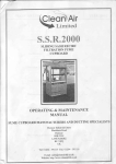
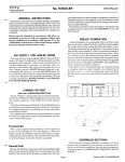
INSTALLATION, OPERATION AND
MAINTENANCE MANUAL FOR
AIL SINCLE PIECE & TWO PIECE
FULL BORE BALL VALVES
1.0
STORAGE OF VALVES
On receipt. check rhe valve to cnsure that it is in full-v
assembled condition and in the open position.
End protectors on thc valve should be kept itttact and
removed only at the time of installation. \"alvc
performance dependson prevention of damage to the
ball,'seatsurfaces.
V'alvesshould be stored in a covered arca. If covered
area is not ar.ailableany water proof covering material
should be sprea<ior.er the valr.es and they should be
kept on a u.ooden pallet at least l50mm above the
ground ler.el.
Do not apply tar. paint. greasc or any other ntaterial
inside the valr-c or on the stcnr.as this could impair
the performance of valve.
2.0
INSTALLATION
2.1
GENERAL
When despatchcd.r'alvescontain a rust prcventor and
if necessarymay,-be removed rvith a solvent.
Before installation cnsurc that thc pipcline has be-en
flushed on line scale. rr'cld spattcr. rust and othcr
foreign mattcr.
Ensurethat the end protectorsare removedat the time
of installation.
3. 0
OPERATION
3.1
GENERAL
AIL Ball valvesprovide bubble tight shut off rvhen
used in accordancervith our publishedpressure/
temperaturechart.
It is not the right practiceto leave the valves in a
partiallyopen(throttled)positionas this can damage
the seatsand adr.erselyaffect its performance.
Any mediathatmay solidify.crystalliseor polymerise
shouldnot be allou.edto rcmain in the rralvecavity
as it can affect the operationof the valve.
3.2
MANUALOPERATION
AIL Ball valveshavea quarterturn operation.closing
in a clocku'isedirection.It is possibleto determine
rvhenthe valve is open or closedby the positionof
the ler.er.When the lever is in line rvith the pipeline,
the valve is open.and u'hen at 90o to the pipelineit
is closed.
REMOTEOPERATION
When manualoperationis not desired,valvesmay be
automatedfor remoteoperation.A rangeof pneumatic/
electricactuatorsand gear units are availablefor
mountingon AIL Ball valves.
unit
No stopperplateis fitted on actuatedvalves/gear
valves.as the stop is normallya part of the actuatori
gear unit.
For operationaldetails of thc actuators,refer to
installationmanualof the actuator.
4.0
MAINTENANCE
4.1
GENERAL
AIL Ball Valves have a long trouble free life. and
is seldomrequired.But rvhennecessary.
maintenance
valr.esmay be refurbishedr.ery easilyby using feu'
u'hichdo not requiremachiningat site.
components.
AIL Ball Valves are designcdfor easy serviceand
a s s e m b l yi'n f i e l d . T h e f b l l o u . i n g p o i n t s r v o u l d .
ho*,ever,help to extendvalve lif-efurtheqor reduce
operationalproblems.
4.2
STEMLEAKAGE
Remove the rvrcnch assemblv.Exarninethe disc
springs(BelleVille'Washer- applicableupto40mnr)
for damage.lf in eractcondition.tightentheglandnut
If damaged.
until thediscspringsarefully compressed.
dismantlethe stem dou.n to the gland. fit nerv disc
springsrvith thcir outer edgestouchin-eand tighten
requires
using a ne\\' cland nut. Furthern:aintenance
dismantlingof the valve.
If the stem leakageis not arrestedbir the above
procedure.dismantlethc vah..e.Hott'e\.erdo not disturb
the stem assemblfif no stem leakageis noticed.
4.3
]N-LINETHROUGHLEAKAGE
C'heckthat the valve is fully closed condition. If it is,
then the leakage is possibly' due to a damaged seat/
ball or sealing surfaces and it s.ill be necessary to
dismantle the valve to rectify it.
4.4
REFURBISHING
Usc only genuine AIL Ball \'alve spares. These can
be ordcred on our distributorsand authorisedstockists.
Parts of r.alves fiom dilfercnt sizes of seriesmust not
be interchanged.
This is irnpor-tantas it ensuresthat the valve is capable
of bein-r.used for the purpose it r.vasdesigned and
constructed and operatcd without risk to health and
safctl.'.
4.5
SAFETYPRECAUTIONS
Bcfbre removitr-uthe valve fiorn the pipeline. enstrrc
that adequatesaf-etyprecautioltsare taken, as the mcdia
floiving through the valve may be corrosive. toxic.
inl'lammable or contantinated. It is advisable to use
shields, gloves anci safety shoes.
safcty gear like e-"-'e
Ensure that bcfbre rerpoyin_ethe r.alve firtrn the line
no pressureexistson the upstreamor domlstream sides
of the r-alve.
Before rentttvitrg thc valre cnsure that any trapped
media is rclcasedb1'openingthe valrc sloil'l-vto half
open position.
i^,tench
i\jut
@-
SranE vliasier
Sloc P'r
3:3nd Nu:: Berle!:lje
v"r3hers
Gi?na
GiandPac(ing-
Slefi Th.us: Sea'
_-bs
Explodedview of Ball valve 'l5mm to 40rnm
5
iirenc\ ;rx'nE Eoli
i'irenct Fead
Siaqc fiul
Lrcki4g Clip
3land Nui
Slco ind,calor
Gl3nd
Clandoac(nE
Siea Lmatioi Ring
Seccidan/ Sten Seal
Bodv:cnnectol
3c'ew
Seat Rrng
-
Sail
Seal Rilg
Slefl:hrrsl
Seal
Sler
Explodedview of Ball valve 50mm and above
4.6
DISMANTLING
Removethe valvefrom the pipelineby extractingthe
flangebolting from eachend. Largepipelines(srzes
80mmandabove)har.ea tendencyto springtheflanges
and removalcan be difficult. If necessaryremove
e l b o r v s .c o u p l i n g so r p i p e s u p p o r t st o g e t e x t r a
maneuverability.
The valvecanbe removedin eitherthe openor closed
position.
Hor.vever,
if it is open.it ensuresthat no line media
lies pressurised
rvithin the vah,e car.ity.
With ther.alvesecurelyclamped(r'crtically,insertside
f-acing
thetop)andin theopenposition.undothe insert
usingtheappropriatedrive adaptor.It may benecessary
to use a heavy n-ralleton the tommy bar of the insert
tool to breakthemetalto metalsealandmovethe insert
initially.
Removethe inser-tto allow accessto the cavity.Thc
insertshouldbe remor.edout of the body completely
as otherwise its seal face may be damagedlnot
applicablefor 2 piece design).
In caseof 2 piecedesign.removethe interconnecting
bolts betrveenbody and body connector.
Remor.ethe body sealanddiscard.Ifthe sealis difficult
to renlovethan use a scriberor sharpbladed
scrervdriverand dig into the body sealat an anglefar
enoughto pror.idepositive location.Lever out one
sectionof the sealfrom its recessandpull it out using
a long nosepliers.
Closethe ball and usinga soli drift throughthe body
port. tap out the ball and insert seat.
Turn the stemback to thc open positionand using a
suitablehook pull out the body seatbeingcarefulnot
to damagethe seatsealingface and the fire safelip
on the l.all.e body'.
To dismantlethe stem assembly'removethe rvrench
nut, rvasherand rvrench from the stem. Using the
rvrenchto preventthc stentlrom turning,removethe
gland nut and the gland. Tap the stem dou'n and
rvithdrau.it from insidethc body.The glandpacking,
o' ring and the stem sealcan now be removedfrom
(from 5Ommonu'ards).beingcarefulnot
theirrecesses
the seal faces.
to dan-rage
All componcntsmust bc inspectedfor u'ear and
Partsthat are not to be replacedshouldbe
dama-sc.
thoroughly cleanedand stored in a clean area.All
sealingfaceson the body. insert and ball must be
If dan-rage
checkedfor corrosion.erosionandscratches.
doubt.replacethe component.
is foundor thereis an1,'
Cleariingof valve parls sliould be carriedout using
a suitabledegreasinuagent.Hard depositscan be
remor,edusingu'ireu'ool or by usinga hardblunt tool.
Careshor"rld
be takcnnot to dantageor scratchan.vof
faces
and machinedfaces.
the seal
4.7
REBUILDING
B e f o r c r c b u i l d i n e .c h e c k t h a t a l l t h e c o r r e c t
componentsare availableand thc,vare fit for the
is essentialto
\\"henrebuildingcleanlincss
plrrpose.
allow long valve life and provide cost effective
maintenance
Fit the new gland packinginto the body recess,the
gland and new disc springs(with their outer edges
touching)onto the stem.This is applicableonly upto
40mm size.
Fit the gland nut, pre\.entthe stem from turning and
tightendou'nto fully compressthe disc springs(only
upto 40mm size).
Fit thervrench,rvasherand rvrcnchnut to the stemand
operatethe stem to the valve open position.
Securethe valr.ein a verticalltosition.rvith insertside
facingupu'ards(upto40 ntm) or body connectorfacing
upu,ards(from 50mnr& above).With the body seat
endon,enterit into thevalvecar.itvpastthestemdrive
tang.then positionit into the seathousing.A silicon
basedgreasemay be appliedto thc seatface to aid
bedding in of the r.alve.
Turn the stemto valr,eclosedand slide the ball into
the body locatingthe stem drir.e rang.
Havin-qapplied silicon greasefor sizesupto 40mm
locatethe insertend seatinto the cavity and the body
sealintothehousing.For sizes5Ommandabove.locate
the body connectorend seatinto the car,ityand bodv
seal in to the housing.
Open the valve and scrervthe insert for sizes upto
40mm into thevalr.ebody usinga suitabledrive adaptor
for sizes50 mm & abovebody connectorshouldbe
put into the body and tighten the fasteners.It is
importantthaton stainless
steelvalvesan anti scuffins
compoundis usedon the insertthread.It is advisable,
thoughnot mandatoryto use it on carbonsteelvalves.
The valve is now readyto be put in line. If possible,
leaktightnessandeaseofoperationshouldbe checked.
10
lnstallation,Operation &
liiaintenanceManualfor
AIL Ball Valves
( 3 - P I E C ED E S I G N )
1, STORAGE OF VALVES
On receipt,check the valve is in fully assembledcondition and
in open position.
End protectors on the valve should be kept intact and removed
only at the time of installation- Valve performancedepends on
preventionof damage to the ball surface'
Valvesshould be stored in a covered area. lf covered area is not
availableany water proof covering materialshould be spread over
the valves and the valves should be kept on a wooden pallet
atleast6" above the ground level.
Do not apply tar, paint, grease or any other material inside the
valve or on the stem, as this could impairthe performanceof the
valve.
2. INSTALLATION
General
When despatched,valves contain a rust preventiveand this may
be removed with a solvent if necessary.
Before installationremove all foreign matter in the pipeline by
flushingthe line with the water or compressedair, keeping the
valve fully open.
SCREWEDEND VALVE
Do not dismantlethe valve for installation.Screwedends should
treat the valve as a single unit. taper
not be fitted independently,
threadedfittings should not be over tightened.
WELD END VALVE
The instructionsent along with each valve must be followed-
3. OPERATION
in a clockwise
AIL BallValveshavea quarterturn operation-closing
direction. lt is possibleto determinewhen the valve is open or
closed by the positionof the lever. When the lever is in the line
with the pipeline,the valve is open: when the lever is across the
pipeline,the valve is closed.
Where manualoperationis not desired,valvesmay be automated
for remote operation.A range is pneumaticactuatorsis available
for mounting on AIL Ball Valves.
No stopper plate is fitted to the remote operated valve, as the
stop is normallya part of the actuators.
For operationaldetails of the actuators, refer installationmanual
of the actuator.
4. MAINTENANCE
General
AIL Ball Valveshave a long, trouble-freelife, and maintenanceis
seldomrequired. But, when necessaryvalvesmay be refurbished
very easily by using few componenls, which do not require
machiningat site. AIL Ball Valvesare designedfor easy service
and assembly in the field. The following checks would however,
help to extend valve life further,or reduce operationalproblems.
Stem Leakage
Examinethe disc springs (BelleVille washer) for damage. lf in
exact condition, tighten the gland until disc springs are fully
compressed. lf damaged,dismantlethe stem down to the gland,
fit new disc springswith their outer edges touching and replace
using a new gland nut. Further maintenance necessitates
dismantlingof the valve.
Leakage at body joint
Check for tightnessof the body connectorbolts. lf slack, tighten
the bolt using standardwrenchesonly. Avoid excessiveforce as
this will be due to the damagedbody connector seal and oil will
be necessaryto dismantlethe valve.
I n l i n e l e a ka g e
Ensurethat the valve is fully closed. Leakageif noticed will be
due to a damaged seal or ball seating surfaces and it will be
necessarvto dismantlethe valve.
lf the stem or body leakageis not arrested by the above simple
procedure,dismantlethe valve. However,do not disturb the stem
assemblyif no stem leakage is noticed.
Leakageat PiPelineioint
Screwed Valves
Testfor tightnessof screwedends. lf slack,tightenwith standard
wrench - excessiveforce will only split the connecter.normal
jointing material should be used in the correct quantity'
Weld end valves
After welding the valves as per procedure detailed in para 8,
pressuretest the welded joints for leakage. lf necessaryre-weld
again as Per the Procedure.
5. REFURBISHING
spare parts can be ordered on our Distributorsand Stockists.
Where a va|ve needs repairing,rather than maintaining,it must
be noted that only genuine spare parts should be used'
Partsof valvesfrom differentseries,should not be interchangedThis is to ensurethat the valve remainscapable of being used
for the purpose for which it was designed and constructedand
operated without risk to health and safety'
Tools
No specialtools are requiredfor maintenanceof AIL Ball Valves
of 3 piece design.
6 . SA F ET YPR E C A U T ION S
Before removing the valve from pipeline,ensure that adequate
safetyprecautionsare taken, as media flowing through the valve
may be corrosive, toxic, inflammableor contaminaled.lt is
advisableto use safety gear like eye-shields,gloves,& footwear.
Ensuretl-ratbefore dismantlingthe valve no pressureexists either
on upstreamor downstreamsides of the valve.
Ensurethat any trapped media is releasedby operatingthe valve
slowlyto half open position (decontamination).
Body connectors form an integral part of the pipeline and the
valve cannot be removed from the pipeline without being
dismantled(seeDISMANTLINGProceduredetailedin Para 7).
7. DISMANTLING
lf the valve is closed and not in fully open position, refer to
the safety precautionsbefore proceedingfurther.
Also,during dismantling,do not assumethat the valve is totally
decontaminatedas harmfulfluid, may still be trapped in crevices.
To removevalve from pipeline,extract body connector bolts and
slide the body out from betweenthe body connectors.lt is often
not necessaryto remove the body completelyaway from the
pipeline,in such cases,removethree of the body connectorbolts,
and with the fourth bolt slackened,the body may be rotated out
from the line usingthe fourth bolt as hinge.(Feferfig.1)
The ball musf be in the open position since a closed ball
protrudesbeyondthe body cavityand ballwill be damagedagainst
body connectorswhen body is removed or rotated.
lf the body connectorseals come away easilyduring removalof
body, they may be removedat that time. lf not, leavethem until
later .
When the body is free of the body connectors,turn valve to half
closed position and hook out seats with finger. Completelhe
closing turn and - the ball may be pushed out to fall on to- handthis must be done carefully,otherwisethe ball will mark against
the body.
The body connectorseals should now be removed. Care must
be taken to avoid scratchingthe machinedfaces on which they
make contact with the valve body.
Todismantlestemassembly,firstremovethe levernut, identification
plate and lever from stem. Using lever to preventthe stem from
turningthe gland nut, disc springsand gland. lt is not normally
possibleto remove gland packing at this stage. Withdraw stem
through body cavity and remove stem thrust seal from stern or
body recess. Gland packing may now be removed.
In the 15mm size.the wrenchfiats on the stern must be aligned
perpendicularto the line to allow withdrawalof the stem.
Cleanall componentsthoroughlyand examineall seatings/sealing
surfaces.
O)
tl-
lf there is a build - up of solids which cleaningfluids will not
dislodge-donot scratchthe machinedsurfaces-use a broad' flat,
blunttool.
No eroded or corroded leak parts are permissible. lf any are
found, the part must be replaced. The ball should not have
scratchesacross its seating surfacesas any damage to the pon
lip as this will destroy the seats. A damagedball must not be
re-used,fit a new one .
8 . R E B U I L D I N G ( R e f e rF i g . 2 l
Before rebuilding,check that all the correct componentsare
availableand ttrat they are fit for the purpose- When rebuilding'
cleanlinessis essentialto allow long valve lile and provide cost
effectivemaintenance.
Fit stem thrust seal to stem and insert stem through body cavity
into stem hole and fully up into body recess. Fit gland packing,
gland and disc springswith their outer edges louching Using
leverto preventstem from turning, fit gland nut and screw down
until disc springs are firmly compressed. Operate stem several
limes and re-adjust. Overtighteningwill only reduce the life of
the assembly. Now fit stop plate, lever, identificationplate and
lever nut to stem assemblyand move leverto the closed position
(leveracross the pipeline). In sizes 112"& 3/4" lever has integral
stopper and there is no separatestop plate.
Wilh the leverstill in the closed position,the ball may be inserted
into the body cavity by sliding the ball slot ovei'the stem tang.
Open the valve.
The ball must be in the open position since a closed ball
protrudesbeyondthe body cavityand ballwill be damagedagainsl
ul
\
o
-P rP
F
f,
c
o
?
rU
. ! - 2 :
. , " i u c
F
Y
z
<
) = z o z u*
a
O
^
-
6
O
z - z > z
P
<J (A
r
r A y Hl
]
=
o
< 5
r u
z
-
o
o
o
o
U
U
-
J
)
o
O
c
l
6
ii
a
F * s
h ;
B H
d:6
H
; ;
zi22
* H s 3
j j - z ^6 a
s ; s B3
_---r__i
body connectorswhen the body is removed or rotated . Also,
with the valve in the open position,the ball is retained by the
stem tang and cannot fall out of the body cavity.
The seat rings and body connectorseats may now be fitted.
A trace of lubricatingoil or petroleumjelly, if compatiblewith the
future pipelinemedia . will easethe rebuildingby holdingthe seat
rings and body connector seals in place. Do not use greases
with abrasiveadditives.
The valve may be installedback in to the pipeline by slidingthe
body in between the body connectors. The pipeline should,
however,be sprung apart sufficientlyto clear valve body and
avoid damage to seat rings, body connectors seals and body
connectorssealingface.
Locate body on center line of pipework,fit body connectorbolts
and nuts and by tightening,pull together body connectors. Use
only standardwrencheslor tightening,as excessiveforce will only
stretch or strip the studs.
Weldinginslructionsfor socketlveld ends - AIL Ball Valves(Size
112"ro 2" )
1.
Prepareclean workingarea.
2.
Smoothenpipe ends to removeany burrs.
3.
With valvein OPENpositron.removelhe body conneclor
bolts. Removethe body connectors from body and
turn the ball to paft ciosed position
4.
Carefully remove the ball seats and body seals.
Supportingthe ball so as to prevent it from falling out
of the body,turn to closedposiiionand removethe ball.
1a
5
Place all removed parts in clean and secured position.
o
Reassemblethe body alone with body connectorsand
tack weld only the valve to the pipeline. Remove the
body to prevent damage to stem seals from welding
heat.
7.
Thencompletethe welding,ensuringthat body connector
faces are protected from weld splatters.
B.
When cool clean body connectorfaces carefully.
9.
Fit the ball, ball seats and body seals into the'body.
10.
In the case of ball valves with graphite body seals
(eg.AW44)care should be taken that the body sealsare
not damaged during disassembly.For this the valve is
tack welded into pipeline without applying excessive
heat. Then the body assemblyis removed intact. Do
not remove body sealsas they are very briftleand likely
to break, if not handled properly.Then weld the enC
connectionsas explainedin steps B & I .
11.
Easebody assemblybetweenbody connectorscarefully,
keepingthe ball in open position,withoutdamagingfaces
or seals.
12.
Replacebody connectorbolts and working in a diagonal
order tighten the nuts firmly.
Test
A test for leak tightnessis recommended.