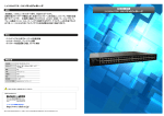
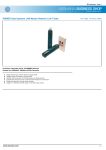
1
™
LANMaster T8
8-Port Ethernet Hub w/SIC Slot
(E-TBT-HB-0802)
7364.A
For assistance in installing, using, or
maintaining the TRANSITION Networks
LANMaster T8 10BaseT Ethernet™ Hub,
contact TRANSITION Networks
Technical Support at:
(800) 260-1312
or contact your local distributor.
TN’s total liability in connection with the products and installation thereof to
all persons and from all causes in the aggregate whether in contract, tort, or
strict liability shall not exceed the amount paid to TN for the product directly
related to the alleged damage. However, in no event shall TN have any
liability to a customer or any third party with respect to a product
manufactured in accordance with customer’s specifications.
C. Return Procedure
Compliance Information
UL Listed
FCC Regulations
This equipment has been tested and found to comply with the
limits for a Class A digital device, pursuant to Part 15 of the FCC
Rules. These limits are designed to provide reasonable protection
against harmful interference when the equipment is operated in a
commercial environment. This equipment generates, uses, and can
radiate radio frequency energy and, if not used in accordance with
the instruction manual, may cause harmful interference to radio
communications. Operation of this equipment in a residential area
is likely to cause harmful interference in which case the user will
be required to correct the interference at his own cost.
Canadian Regulations
This digital apparatus does not exceed the Class A limits for radio
noise for digital apparatus set out on the Radio Interference
Regulations of the Canadian Department of Communications.
Copyright Restrictions
© 1995 TRANSITION Networks Inc.
All rights reserved. No part of this work may be reproduced or
used in any form or by any means – graphic, electronic, or
mechanical – without written permission from TRANSITION
Networks Inc.
Before TN item(s) can be returned, a Credit Return Authorization (CRA),
Return Material Authorization (RMA), or Material Repair Authorization
(MRA)number must be obtained from TRANSITION Networks (TN) or the
distributor of origin.
Locate the serial number(s) of the item(s) to be returned. From the item serial
number, TN or the distributor will verify the return status and provide the
appropriate number to the End User. The three types of return numbers are
listed below:
• A Credit Return Authorization (CRA) number can only be requested from
your distributor. This CRA number will only be issued to distributors for
item(s) within 90 days from the original ship date. Under no
circumstances will a CRA number be issued directly to the End User. The
return item(s) must be shipped freight prepaid, by the End User or the
Distributor to TN.
• A Return Material Authorization (RMA) number can be requested from TN
or your distributor. This RMA number is only issued for item(s) after 90
days from the original ship date but prior to the expiration of the warranty
period. The return item(s) must be shipped freight prepaid, by the End
User or Distributor, to the TN address below:
TRANSITION Networks Inc.
6475 City West Parkway
Eden Prairie, MN 55344 USA
TRANSITION Networks will repair or replace the unit, at its discretion,
and cover the cost of the return freight to the distributor or End User who
was issued the RMA number.
• A Material Repair Authorization (MRA) number can be requested from TN
or your distributor. This MRA number is only issued for out-of-warranty
item(s). The return item(s) must be shipped freight prepaid, by the End
User, to the TN address above. The sender will be contacted by TN after
the item(s) have been received, inspected, and a cost estimate of the
repair has been determined. The repair charges may be billed, with
approval, through your distributor or prepaid/C.O.D. basis through the
End User. In either case, charges will include freight, both ways, and
repair charges.
The return authorization number is only valid for 60 days from the date of
issuance. Please list this number on the outside of the carton and/or packing
list. Include a copy of the original invoice or packing slip to expedite
processing.
D. Restocking Fee
Trademark Notice
All registered trademarks and trademarks are the property of their
respective owners.
LANMaster T8
All returns for credit must be received in the same condition as originally
shipped. If TN determines that a returned product is damaged due to improper
packaging or if the item is functional and returned because of customer error,
inability to use, etc., TN reserves the right to charge a minimum 15% ($10.00
minimum per item) restocking fee, the payment of which is a condition
precedent to the repair and/or return of the product.
8-Port Ethernet Hub w/SIC Slot
20
Policy And Procedure
A. Limited Warranty
TRANSITION Networks (TN) warrants, for a period of two years (with the
exclusion of five years for passive balun products) from the date of shipment to
the original purchaser and at the original point of installation, that products of
TN’s design will be free from defects in materials and workmanship and in
conformity with TN’s specifications. TN’s sole warranty with respect to products
manufactured or assembled by TN in accordance with a customer’s
specifications is a two year warranty that such goods conform to such
specifications. These warranties do not extend to goods that have been subject
to alterations, misuse, accident, tampering, improper maintenance, improper
installation or abuse.
THE ABOVE WARRANTY IS EXCLUSIVE AND EXTENDS ONLY TO PRODUCTS
ASSEMBLED BY TN, AND TO THE EXTENT PERMITTED BY LAW, TN DOES NOT
MAKE AND DISCLAIMS ALL OTHER WARRANTIES (EXCEPT TITLE), EXPRESSED
OR IMPLIED, INCLUDING BUT LIMITED TO ANY WARRANTY OF
DESCRIPTION, MERCHANTABILITY, FITNESS FOR A PARTICULAR PURPOSE
OR NON-INFRINGEMENT AND ANY WARRANTY BASED UPON PRIOR
WRITTEN OR ORAL REPRESENTATIONS REGARDING SUCH PRODUCTS
MADE BY TN, ITS EMPLOYEES, AGENTS, OR REPRESENTATIVES.
B. Limitations and Exclusions
If customer believes any goods sold hereunder are defective pursuant to the
warranty and within the warranty period set forth above, the customer must
notify TN within such period. TN will promptly issue a return form for such
goods. Upon receipt of the form, customer is to promptly return the allegedly
defective goods at customer’s expense and shipped prepaid to your distributor or
TN (refer to the next subsection C, Return Procedure).
No goods will be accepted for return unless a prior return form is obtained from
TN, freight charges have been prepaid by customer. TN or the distributor shall,
at its option, either (i) repair such goods free of charge if warranty within two
years, (ii) repair such goods at a minimum of $100 (One Hundred dollars) per
item if warranty expired, (iii) replace such goods free of charge, or (iv) accept
the return of such goods and credit current price therefore to the customer.
THIS IS THE EXCLUSIVE REMEDY FOR ANY BREACH OF WARRANTY. IN NO
EVENT SHALL TN BE LIABLE FOR SPECIAL, INDIRECT, INCIDENTAL OR
CONSEQUENTIAL DAMAGES OF ANY KIND, WHETHER FOR BREACH OF ANY
WARRANTY, FOR BREACH OR REPUDIATION OF ANY OTHER TERM OR
CONDITION OF SALE, FOR NEGLIGENCE , ON THE BASIS OF STRICT
LIABILITY, CONTRACT, OR OTHERWISE AND IRRESPECTIVE OF WHETHER TN
IS INFORMED BY CUSTOMER OF THE POSSIBILITY OF SUCH DAMAGES IN
ADVANCE OF THIS SALE.
The sole purpose of this remedy shall be to provide the customer with the
replacement or repair of non-conforming goods in the manner provided here-in.
This exclusive remedy shall not be deemed to have failed of its essential purpose
so long as TN is willing and able to repair or replace the non-conforming goods
or refund the purchase price therefore in the manner provided herein.
TN reserves the right to inspect products claimed to be defective under warranty
either at the customer’s location or at TN's plant. TN assumes no liability for
labor charges incidental to the adjustment, service, repairing, removal or
replacement of the product or other costs, or the expense of repairs made
outside of its factory except when made pursuant to TN's prior written consent.
All returns must be received in the same condition as the original shipment.
19
LANMaster T8
Table of Contents
1 INTRODUCTION . . . . . . . . . . . . . . . . . . . . . . . . . 1
The LANMaster T8 8-Port Ethernet Hub w/SIC Slot . . . . . . . .1
LANMaster T8 Features . . . . . . . . . . . . . . . . . . . . . . . . . . . . . . .1
Networking the LANMaster T8 . . . . . . . . . . . . . . . . . . . . . . . . .2
Connectors, Indicators and Switches . . . . . . . . . . . . . . . . . . .3
2 SITE CONSIDERATIONS. . . . . . . . . . . . . . . . . . . . 4
Ensuring Compliance with 5-Segment Rule . . . . . . . . . . . . . .5
Ensuring Correct 10BaseT Configuration . . . . . . . . . . . . . . . .6
3 INSTALLATION. . . . . . . . . . . . . . . . . . . . . . . . . . . 7
Unpacking the LANMaster T8 . . . . . . . . . . . . . . . . . . . . . . . .7
Installing LANMaster T8 on Flat Surface . . . . . . . . . . . . . . . .8
Connecting 10BaseT Cable at LANMaster T8 Front . . . . . . . .9
Installing Slide In Cards . . . . . . . . . . . . . . . . . . . . . . . . . . . .10
Connecting Cable to Slide In Cards . . . . . . . . . . . . . . . . . . .11
Twisted Pair Connector/10BaseT Connection . . . . . . . . . . . . .11
Female AUI Connector/10Base5 Connection . . . . . . . . . . . . .12
Male AUI Connector/PC Connection . . . . . . . . . . . . . . . . . . . .12
BNC Connector/10Base2 Connection . . . . . . . . . . . . . . . . . . .13
Fiber Optic Connector/Fiber Optic Connection . . . . . . . . . . . .13
Powering the LANMaster T8 . . . . . . . . . . . . . . . . . . . . . . . .14
4 OPERATION . . . . . . . . . . . . . . . . . . . . . . . . . . . . 15
Monitoring Power LED . . . . . . . . . . . . . . . . . . . . . . . . . . . .15
Monitoring Port/Indicator LEDs . . . . . . . . . . . . . . . . . . . . . .15
5 MAINTENANCE . . . . . . . . . . . . . . . . . . . . . . . . . 16
LANMaster T8 SPECIFICATIONS . . . . . . . . . . . . . . . . . . . . . 17
CABLE SPECIFICATIONS . . . . . . . . . . . . . . . . . . . . . . . . . . . . 17
POLICY AND PROCEDURE . . . . . . . . . . . . . . . . . . . . . . . . . 19
8-Port Ethernet Hub w/SIC Slot
i
10BaseT Cable Specifications
1. INTRODUCTION
This guide is intended for the system or network administrator
responsible for installing and monitoring a TRANSITION Networks
LANMaster T8 8-Port Ethernet Hub w/SIC Slot. A working
knowledge of local area network (LAN) operations, including
familiarity with communications protocols used on interconnected
LANs, is assumed.
The LANMaster T8 Hub w/SIC Slot
The LANMaster T8 8-Port Ethernet Hub w/SIC Slot (E-TBT-HB0802), is a stand-alone, fully functional Ethernet repeater.
LAN Master™ T8 8 Port Ethernet Hub w/SIC Slot
1
2
3
4
5
6
7
8
The physical characteristics of the 10BaseT cable must meet or exceed
IEEE 802.3 10BaseT specifications.
Either shielded or unshielded twisted pair can be used. Level 3 wire or
better is recommended.
• Gauge. . . . . . . . . . . . . . . . . . 26 to 22 AWG
• Attenuation . . . . . . . . . . . . . Less than 11.5 dB @ 5-10 MHz
• Differential Characteristic . . 85 -110 Ω Impedance
@ 10 MHz
• Maximum Distance . . . . . . . 100 Meters (330 Feet)
Segment Distance
Media
Segment
Type
Maximum
Number
MAU/
Segment
Maximum
Segment
Length
(meters)
Minimum
Medium
Propagation
Velocity†
Maximum
Medium
End to End
Propagation
Delay/Segment
10Base5
10Base2
100
30
500
185
0.77 c
0.65 c
2570
950
AUI ††
1 DTE/MAU
50
0.65 c
257
10BaseT
2
100 †††
0.59 c
1000
FOIRL
FL
2
2
1000 ††††
2000
0.66 c
0.66 c
5000
5000
T R A N S I T I O N
n e t w o r k s
Minneapolis, MN 55344 USA
MDI/MDIX
LANMaster T8 8-Port Ethernet Hub w/SIC Slot Features
•
Media Dependent Interface (MDI) switch eliminates need
for RJ-45 crossover cable connection between LANMaster
T8 devices.
•
Comes with internal power supply.
•
Complies with Ethernet 802.3.
•
Slide-In Card (SIC) slots for optional installation of
additional media connections.
†
††
†††
††††
1
LANMaster T8
c = 3 x 10⁸ meters/second
AUI connection is not a segment
Maximum segment length depends on the cable characteristics
A network of four repeaters and five segments, can have up to 3
coax segments and 2 required link segments. The maximum
length of a FOIRL link segment must not exceed 500 meters. If
your network has three repeaters and four segments, the
maximum length of a FOIRL link segment must not exceed 1000
meters.
8-Port Ethernet Hub w/SIC Slot
18
LANMaster T8 Specifications
Dimensions
9.25" X 7.75" X 1.75"
(235mm x 197mm x 45mm)
Environment
Temperature:
Humidity
Altitude
Networking the LANMaster T8 8-Port Ethernet Hub
w/SIC Slot
10BaseT connections can be made to terminal equipment and to
other LANMaster T8s.
Additionally, optional Slide-In cards (SICs) can be installed at the
back of the LANMaster T8 to provide a connection to the network
backbone.
0-50°C,
10-90%, non condensing,
0-10,000 feet.
SIC Connection
Cable Specifications
10Base2 Cable Specifications
The physical characteristics of the 10Base2 cable must meet or exceed
IEEE 802.3 10Base2 specifications:
. . . .
. . . .
. . . .
. . . .
• 50 W RG-58 Ethernet approved cable.
10BaseT (100 meters)
10Base2 (185 meters)
10Base5 (500 meters)
10BaseFL (2000 meters)
AUI Cable Specifications
The 15 pin AUI cable must be IEEE approved.
. . . .
. . . .
10BaseFL Cable Specifications
. . . .
. . . .
The IEEE 802.3 standard for fiber optic segments are:
• 62.5/125µm multimode fiber (recommended).
• 100/140 µm multimode fiber.
• 85 µm multimode fiber.
• 50/125 µm multimode fiber.
. . . .
. . . .
. . . .
. . . .
. . . .
. . . .
. . . .
. . . .
17
LANMaster T8
8-Port Ethernet Hub w/SIC Slot
2
Connectors, Indicators and Switches
5. MAINTENANCE
WARNING: DO NOT, UNDER ANY CIRCUMSTANCES,
open and attempt to repair the LANMaster T8 8-Port
Ethernet Hub w/SIC Slot or power supply adapter unit.
Failure to observe this warning could result in personal
injury or death from electrical shock.
INDICATORS
CONNECTORS
1 2 3 4
5 6 7 8
NOTE: Failure to observe the above warning will immediately void
the warranty.
Power
MDI SWITCH
Technical Support Contact
Connectors
Eight (8) RJ-45 10BaseT connectors are located on the front of the
LANMaster T8 Hub. One (1) power connector is located on the back
of the LANMaster T8 Hub.
NOTE: Slide-In cards (SICs) can provide optional additional fiber
optic, male and female AUI, BNC, and RJ-45 connectors
For assistance in fault isolation and in maintaining the LANMaster
T8 8-Port Ethernet Hub w/SIC Slot Pocket Hub, contact:
Technical Support
(800) 260-1312
or your local distributor.
LEDs
The Power LED indicates the LANMaster T8 Hub connection to
external power. The Port Indicator Link/Partition LEDs indicate (for
each port) the status of the LANMaster T8 Hub connections to the
10 BaseT network.
MDI/MDI-X Switch
The MDI/MDI-X switch allows the RJ-45 connection at Port 8 to be
changed from straight-through to crossover.
3
LANMaster T8
8-Port Ethernet Hub w/SIC Slot
16
4. OPERATION
2. SITE CONSIDERATIONS
The LANMaster T8 8-Port Ethernet Hub w/SIC Slot normally
requires no intervention beyond occasionally monitoring the Power
and Port Indicator LEDs.
The site for the LANMaster T8 8-Port Ethernet Hub w/SIC Slot must
provide:
Port Indicators
Link/Partition
Power
•
AC power outlet for each LANMaster T8 8-Port Ethernet
Hub w/SIC Slot
• Adequate ventilation
• Standard environmental conditions
• Isolation from electrical noise, including radio transmitters
and broadband amplifiers, motors, high power electrical
lines, or fluorescent light fixtures.
Additionally:
•
1 2 3 4
•
•
•
5 6 7 8
Monitoring Power LED
The green Power LED is illuminated when the LANMaster T8 8-Port
Ethernet Hub w/SIC Slot is connected to external power.
And:
•
Monitoring Port/Indicator LEDs
Each of the eight twisted pair ports has an associated LED:
• steady green
data traffic is active on link
• flashing green
port has been partitioned.
15
LANMaster T8
The twisted pair cables should not run in the same conduit
with power line cables.
Phone lines should be separated from data cables.
Flat or “silver satin” wires should not be used.
If using Slide-in Card (SIC) connection between LANMaster
T8 Hubs, the maximum cable distances are:
Fiber Optic
2000 meters
10Base5
500 meters
10Base2
185 meters
10BaseT
100 meters
•
Since the LANMaster T8 8-Port Ethernet Hub w/SIC Slot
functions as an Ethernet repeater, the entire LANMaster T8
8-Port Ethernet Hub w/SIC Slot installation should comply
with the IEEE Ethernet 802.3 specification.
RJ-45 connected cables should be configured as crossover
or straight through according to installation requirements.
8-Port Ethernet Hub w/SIC Slot
4
Powering the LANMaster T8
Ensuring Compliance with 5-Segment Rule
To conform to the Ethernet 802.3 specification, when connecting
LANMaster T8 Hubs, the transmission path between any two Data
Terminating Equipment (DTE) devices can consist of no more than
five segments. NOTE: A segment is the cable connection between
cable interfaces in an Ethernet LAN.
To power ON the LANMaster T8:
1. At LANMaster T8 back, locate the power receptacle and
associated fuse.
NOTE: Fuse must be installed at correct setting for power source voltage
before connecting to AC outlet.
To assign segment numbers to cable connections:
1. Determine the two terminals in the network which are
separated by the greatest number of segments.
2. Assign a segment path between the terminals by labeling the
cable connected to one of the terminals “segment 1” and the
segment connected to the other terminal “segment n” (n =
total number of segments and must be 5 or fewer).
3. To verify that no segment paths contain more than n
segments, assign segment paths and numbers to all other
terminals.
2. Verify that fuse is installed at correct setting for power source
voltage.
NOTE: The installed fuse rating is indicated by the reading at lower right
corner of fuse holder.
If not installed at correct setting for power source voltage:
110-120 Orientation
220-240 Orientation
SIC Connection
220-240
110-120
Fuse Holder
. . . .
. . . .
3
3
•
. . . .
. . . .
. . . .
. . . .
4
2
4
. . . .
. . . .
4
1
. . . .
. . . .
. . . .
. . . .
5
5
. . . .
. . . .
5
220-240
Fuse Holder
Carefully open fuse receptacle, using a small flat blade
screwdriver.
Rotate fuse holder 180° to the correct rating orientation.
Install fuse holder in correct rating orientation.
Close fuse receptacle.
3. Plug unit end (female) of power cord into LANMaster T8 power
receptacle.
. . . .
. . . .
2
•
•
•
110-120
3
LANMaster T8
4. Plug outlet end (male) of power cord into correct voltage AC
wall socket.
5. At LANMaster T8 front, verify that POWER LED is illuminated.
14
BNC Connector/10Base2 Connection
The thinnet coaxial card (E-CX-SIC)
provides a BNC connector to 10Base2.
Ensuring Correct 10BaseT Configuration
50 ohm terminator
NOTE: Verify that coax cables on
LANMaster T8 are terminated properly
at both ends. (In a coax thinnet
installation, the first and last device in
a daisy-chain must be terminated with
a 50 ohm terminator.)
The 10BaseT cable and RJ-45 connectors for Hub to Terminal
connections must be configured as straight through. The 10BaseT
cable and RJ-45 connectors for Hub to Hub connections must be
configured as crossover. NOTE: When installing the LANMaster T8
Hub using the MDI port, a crossover cable is not needed. The MDI
switch can be used to change the straight through configuration to
crossover at port 8.
Additionally, the 10Base2 segment
must be grounded to “earth ground”.
RJ-45 Pin Assignments
50 ohm terminator
1 2 3 4 5 6 7 8
1
8
RJ-45 Plug
RJ-45 Connectors
The two active pairs
in a 10BaseT network
are pins 1 & 2 and
pins 3 & 6. Use only
dedicated wire pairs
(such as blue/white &
white/blue,
orange/white &
white/orange) for the
active pins.
Fiber Optic Connector/10BaseFL Connection
The fiber optic card (E-FRL-SIC) provides one set of transmit (TX)
and receive (RX) connectors to fiber optic cable.
The redundant fiber optic card (E-FL/RED-SIC) provides a back-up
fiber optic connection by providing two sets of transmit (TX) and
receive (RX) connectors to fiber optic cable.
Straight Through Cable
at RJ-45 Plug
Hub . . . . . . . . . . . . . . . .PC, transceiver, NIC, printer
RJ-45 Male . . . . . . . . . . . . . . .RJ-45 Male
1
2
3
6
. . . . . . . . . . . . . . . . . . .1
. . . . . . . . . . . . . . . . . .2
. . . . . . . . . . . . . . . . . .3
. . . . . . . . . . . . . . . . . . .6
Crossover Cable
at RJ-45 Plug
Hub . . . . . . . . . . . . . . .Hub
up to 2000 meters
RJ-45 Male . . . . . . . . . . . . . . .RJ-45 Male
1
2
3
6
13
LANMaster T8
. . . . . . . . . . . . . . . . . . .3
. . . . . . . . . . . . . . . . . . .6
. . . . . . . . . . . . . . . . . .1
. . . . . . . . . . . . . . . . . .2
8-Port Ethernet Hub w/SIC Slot
6
3. INSTALLATION
Female AUI Connector/10Base5 Connection
To install the LANMaster T8 Hub:
• Unpack the LANMaster T8 Hub.
• Install on flat surface.
• Connect 10BaseT Cable at Front.
• Optionally install Slide-In Cards.
• Optionally install Slide-In Card cable.
• Connect LANMaster T8 Hub to power.
The female AUI card (E-AUI-DT-SIC)
provides a female AUI connector for
connection, through an AUI drop
cable, to the 10Base5 port on a
transceiver.
Direction is provided in the pages that follow.
The bridge card (E-BR-SIC) also
provides a female AUI connector for
connection, through an AUI drop cable, to the 10Base5 port on a
transceiver. NOTE: The bridge card enables site-configurable filtering of
packets to and from the network backbone.
Unpacking the LANMaster T8
The LANMaster T8 Hub packing contents should include the
following:
Item
Part Number
LANMaster™ T8
Power Cord
E-TBT-HB-0802
3344, 3347, 3348, 3349, or 3523,
(depending upon power configuration
in country where installed)
User’s Guide
7364
Male AUI Connector/PC Connection
In addition, any of the following optional SICs may be included:
7
Item
Part Number
Thinnet Coaxial
Fiber Optic
Twisted Pair
Female AUI
Male AUI
Bridge
Redundant Fiber Optic
E-CX-SIC
E-FRL-SIC
E-TBT-SIC
E-AUI-DT-SIC
E-AUI-DC-SIC
E-BR-SIC
E-FL/RED-SIC
The male AUI card (E-AUI-DC-SIC)
provides a male AUI connector for
connection, through an AUI drop
cable, to a 10Base5 port on a
powered PC.
LANMaster T8
8-Port Ethernet Hub w/SIC Slot
12
Connecting Cable to Slide-In Cards
Installing LANMaster T8 on Flat Surface
Connections between installed LANMaster T8 SICs or between a
LANMaster T8 SIC and a hub or terminal device include:
To install the LANMaster T8 on table, shelf, or other flat surface:
•
•
•
•
•
1. Carefully turn LANMaster T8 to side.
Twisted Pair Connector/10BaseT
Female AUI Connector/10Base5
Male AUI Connector/PC
BNC Connector/10Base2
Fiber Optic Connector/Fiber Optic.
2. Install four (4) rubber feet:
•
Twisted Pair Connector/10BaseT Connection
The twisted pair card (E-TBT-SIC) provides an RJ-45 connector to
10BaseT.
•
•
•
Remove protective paper from adhesive surface of rubber
foot.
Position rubber foot at bottom corner of LANMaster T8.
Secure rubber foot to LANMaster T8 surface.
Repeat for remaining rubber feet.
crossover
OR
straight-through
To connect 10BaseT Cable to Pocket Hub SIC RJ-45 connectors:
1. Locate or build 10BaseT cables with the following
characteristics:
• 802.3 compliant (See page 18)
• correct (straight through or crossover) cable configuration
for site installation (See page 7)
• male RJ-45 plug connectors installed at both ends of cable.
3. Return LANMaster T8 to upright position.
2. Connect male RJ-45 plug connector at one end of 10BaseT
cable to LANMaster T8 RJ-45 jack connector.
3. Connect male RJ-45 plug connector at other end of 10BaseT
cable to DTE terminal RJ-45 jack connector (using crossover
cable orientation) or to Hub RJ-45 jack connector (using
straight through cable orientation).
11
LANMaster T8
8-Port Ethernet Hub w/SIC Slot
8
Connecting 10BaseT Cable at LANMaster T8
Front
crossover configuration using straight-through cable
Installing Slide-In Cards
CAUTION: Wear a grounding device and observe electrostatic
discharge precautions when installing Slide-In Cards. Failure to
observe this caution could result in circuit board failure.
NOTE: Slide-in Cards can be hot-swapped.
straight-through cable
straight-through cable
To connect 10BaseT Cable to RJ-45 connectors at the LANMaster T8
front:
1. Locate or build 10BaseT cables with the following
characteristics:
• 802.3 compliant (See page 18)
• straight through cable configuration (See page 6)
• male RJ-45 plug connectors installed at both ends of cable.
2. Connect male RJ-45 plug connector at one end of 10BaseT
cable to LANMaster T8 RJ-45 jack connector.
3. Connect male RJ-45 plug connector at other end of 10BaseT
cable to DTE terminal RJ-45 jack connectors.
4. IF CONNECTING TWO LANMaster T8s:
• Connect LANMaster T8s AT PORT 8, using steps 1-3.
•
Set the interface switch on one LANMaster T8 to: MDI and
the interface switch on the other LANMaster T8 to: MDI-X.
Port 8
Setting
MDI
MDI-X
9
LANMaster T8
To install a Slide-In Card:
1. Determine if the Slide-In Cards has an SQE switch and, if so,
verify that the SQE switch is in the OFF position:
NOTE: SQE switches must be set to the following OFF
positions:
•
•
•
•
•
•
UTP/STP card
Thinnet card
AUI-DCE
AUI-DTE card
Fiber Optic card
Redundant Fiber Optic
•
Bridge
TOWARD 20-pin edge connector
TOWARD 20-pin edge connector
AWAY FROM 20-pin edge connector
Not Applicable
TOWARD 20-pin edge connector
SQE jumper setting on board should be
labeled; if not, holding card with 20-pin edge
connector at top, jumper two leftmost pins.
Not Applicable
2. With the Slide-In Card components facing up, carefully guide
the Slide-In Card along the card guides until the Slide-In Card
connector meets the the LANMaster T8 backplane.
3. Firmly push the card into the slot until the Slide-In Card
faceplate is flat against the LANMaster T8 frame.
4. Rotate the Slide-In Card thumbscrews into the LANMaster T8
threaded holes.
8-Port Ethernet Hub w/SIC Slot
10