1
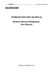
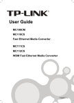
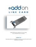
User’s Guide
CSRFB10xx-100
Slide-in-Module Media Converter
•
Copper to Fiber
•
10/100 Bridging (2-Port)
•
10Base-T/100Base-TX to 100Base-FX
The CSRFB10xx-100, 2-port Ethernet/Fast Ethernet
bridging media converter is designed to be installed in
a Transition Networks PointSystem™ chassis. This
converter connects 10Base-T Ethernet or 100Base-TX
Fast Ethernet twisted-pair copper network converters
to network converters on a 100Base-FX Fast Ethernet fiber network. The CSRFB
includes a status reporting feature for viewing operational parameters only from its
remotely attached CSRFB converter via the fiber connection.
Part Number
CSRFB1011-100
CSRFB1013-100
CSRFB1014-100
CSRFB1040-100
CSRFB1029-100
CSRFB1029-101
CSRFB1029-102
CSRFB1029-103
Port One - Copper
10Base-T/100Base-TX
RJ-45
100 m (328 ft)*
RJ-45
100 m (328 ft)*
RJ-45
100 m (328 ft)*
RJ-45
100 m (328 ft)*
RJ-45
100 m (328 ft)*
RJ-45
100 m (328 ft)*
RJ-45
100 m (328 ft)*
RJ-45
100 m (328 ft)*
Port Two - Duplex Fiber-Optic
100Base-FX
ST, 1310nm multimode
2 km (1.2 miles)*
SC, 1310 nm multimode
2 km (1.2 miles)
SC, 1310 nm single mode
20 km (12.4 miles)
SFP Empty Slot
SC, 1310nmTX/1550nmRX
20km (12.4 miles)
SC, 1550nmTX/1310nmRX
20km (12.4 miles)
SC, 1310nmTX/1550nmRX
40km (24.9 miles)
SC, 1550nmTX/1310nmRX
40km (24.9 miles)
Install CSRFB1029-100/101 and CSRFB1029-102/103 singlefiber optic in the same network where one is the local (center)
converter and the other is the remote (terminal) converter.
Installation . . . . . . . . . . . . . . . . . . . . .2
Operation . . . . . . . . . . . . . . . . . . . . .7
Cable Specifications . . . . . . . . . . . . .11
Technical Specifications . . . . . . . . . .12
Troubleshooting . . . . . . . . . . . . . . .13
Contact Us . . . . . . . . . . . . . . . . . . .15
Compliance Information . . . . . . . . .16
CSRFB10xx-100
Installation -- Continued
Installation
CAUTION: Wear a grounding converter and observe electrostatic discharge
precautions while handling the media converter. Failure to observe this caution could
result in damage to or failure of the media converter.
Typical system configuration
The 6-position switch--continued
3.
up
down
4.
Fiber Cable
Chassis Center Converter
SW6 set to ‘Center’
Remote Terminal Converter
SW6 set to ‘Terminal’
Center/Terminal Mode (see note)
up
Center mode (center converter only)
down
Terminal mode (terminal converter only)
Note: To use the TS1000 compliant Center/Terminal mode function, set SW6 on
the center converter in the chassis to Center Mode, the (UP) position; on the
terminal converter at the remote location, set SW6 to Terminal Mode, the
(DOWN) position. This allows you to view parameters of the terminal
converter from the center converter for monitoring purposes only .
The Hardware/Software jumper is labeled “H” for hardware and “S” for software.
The 6-position switch is
located on the side of the
media converter.
Use a small flat blade
screwdriver or a similar
device to set the recessed
switches.
Refer to the drawing to the
right for definitions of the
individual switch positions.
TP Auto-Negotiate (Up=Enabled, Down Disabled)
TP Duplex (Up=Full, Down=Half)
TP Speed (Up=100Mbs, Down=10Mbs)
J6
Hardware
Fiber Duplex (Up=Full, Down=Half)
TLPT (Up=Enabled, Down=Disabled)
Center/Terminal (Up=C, Down=T)
UP
Down
1
2
6.
The jumpers are located on the media converter circuit board. Use small needlenosed pliers or a similar converter to set the jumper.
The 6-position switch
•
Transparent Link Pass Through (TLPT)
up
Enabled
down
Disabled
Hardware/software mode jumper
Note: The Loopback test occurs over the fiber connection.
•
Forces full duplex operation on the fiber port.
Forces half duplex operation on the fiber port.
5.
Network
Chassis
100Mbps
10Mbps
Fiber Duplex
up
down
Network
•
TP Speed (Only valid if SW1 is Down)
2
1.
TP Auto-Negotiation
up
Enables
down
Disables
2.
TP Duplex (Only valid if SW1 is Down)
up
Full
down
Half
3
4
5
6
24-hour Technical Support: 1-200-260-1312 -- International: 00-1-952-941-7600
Software
The media converter mode is determined
H
by the settings on the 6-position switch.
Pins
The media converter mode is determined
by the most recently saved, on-board
microprocessor settings.
S
1
2
H
3
S
Hardware/Software
Note: Software Mode only when the SW6 of the chassis converter is in the UP
position (center).
[email protected] -- Click the “Transition Now” link for a live Web chat.
3
CSRFB10xx-100
Install the slide-in-module
Installation -- Continued
AutoCross jumper
The AutoCross jumper is located on the media converter’s circuit board (labeled NA =
No Autocross; A = AutoCross). See Jumper position below.
Note: Use small needle-nose pliers to set the
jumper.
A
Either straight-through or crossover
cable can be used for all twisted-pair
copper links.
NA
J7
A
Pins
NA
1
2
Ensure that the module is firmly seated inside the chassis.
4.
Push in and rotate the panel fastener screw to secure the module to the chassis
front.
3
A
NA
AutoCross
Note: Factory default is “A” enabled. Transition Networks recommends leaving
the converter in the “A” enabled position.
Panel Fastener
Chassis
J4
All
Pins
Good
1
2
All
Loopback test
3.
Panel Fastener
Mounting Hole
Straight-through or crossover twistedpair cable, depending on installed site
converters, MUST be installed at EACH
twisted-pair copper link.
The Loopback Mode jumper is located on the media
converter’s circuit board (labeled ALL= all frames
plus errors, Good = Good frames only). See Jumper
position to the right.
To install the CSRFB10xx-100 media converter slide-in-module:
1. Locate an empty installation slot on the PointSystem™ chassis.
2. Carefully slide the module into the slot, aligning the module with the
installation guides.
3
Media Converter
Good
Frames
The loopback test is an automatic test run from the center chassis converter with
SW6 set to ‘center,’ the UP position of the switch; and on the terminal converter
with SW6 set to ‘terminal,’ the DOWN position of the switch.
Note: This test is self-running after being initiated through software on the center
converter.
The Loopback test does the following:
1.
The center converter will put the terminal converter in loopback mode.
2.
The center converter sends 100 packets to the terminal converter.
3.
The center converter will monitor its receiver for:
4.
a.
good packets
b.
CRC errors
c.
timeouts
After the center converter receives all 100 packets back or a time out occurs, it
will update its counters and return the terminal converter to its previous mode
of operation.
After completing the test, normal operation of the center and terminal converters is
established automatically.
4
24-hour Technical Support: 1-200-260-1312 -- International: 00-1-952-941-7600
[email protected] -- Click the “Transition Now” link for a live Web chat.
5
CSRFB10xx-100
Installation -- Continued
Install the twisted-pair copper cable
Operation
Status LEDs
1.
Locate IEEE 803.2 compliant 10Base-T or 100Base-TX cable with RJ-45
connectors installed on both ends.
2.
Connect the RJ-45 connector at one end of the cable to the RJ-45 port
connector on the media converter.
3.
Connect the RJ-45 connector at the other end of the cable to the RJ-45 port
connector on the other converter (switch, workstation, etc.).
Fiber LEDs
Link/Activity
Duplex (FD)
Copper LEDs
Link/Activity
(LED2)
Duplex (LED2)
Point System Chassis
RJ-45 Port
Media Converter
Green ON Solid = Link, OFF = no link
Green Blink = Activity
Green ON = Full Duplex
OFF = Half Duplex
Green ON Solid = Link, Blink = Activity
Blink = Rx Data
Green ON = Full Duplex, Blink = Activity
Yellow ON = Half Duplex, Blink = Activity
Green=100 Mbps
Yellow =10 Mbps
RJ-45 Port
On other device
(workstation, switch, etc.)
Locate or build IEEE 803.2™ compliant 100Base-FX fiber cable with male,
two-stranded TX to RX connectors installed at both ends.
2.
Connect the fiber cables to the CSRFB10xx-100 media converter as described:
•
Connect the male TX cable connector to the female TX connector.
•
Connect the male RX cable connector to the female RX connector.
6
Connect fiber cable
to other device
(media converter,
hub, etc.) as shown
LED 2
LED 1
CSRFB
Product Features
Link Test button
Press the Link Test button to bypass TLPT when enabled.
Note: This is a momentary override button; when
released, the connection will return to its previous
state.
Link Test
Connect the fiber cables to the other converter (media converter, hub, etc.) as
described:
•
Connect the male TX cable connector to the female RX connector.
•
Connect the male RX cable connector to the female TX connector.
RX
TX
RX
10/100Base-TX
1.
Connect fiber cable
to media converter
as shown.
TX
Link Test
Install the fiber cable
3.
DPX LACT PWR
10/100Base-TX
Speed (LED1)
Description
ON = Power
OFF = No power
100Base-FX
Note: The MDI (straight-through) or MDI-X (crossover) cable connection is
configured automatically, when the AutoCross jumper is in the enabled
position.
LED
Power
CSRFB
Link Test
Button
AutoCross™
RX
TX
24-hour Technical Support: 1-200-260-1312 -- International: 00-1-952-941-7600
The AutoCross feature detects and configures the twisted-pair copper port on the
CSRFB10xx-100 media converter to the correct straight-through (MDI) or
crossover (MDI-X) configuration. This feature allows either MDI or MDI-X cable
to connect the media converter to converters such as hubs, transceivers, or network
interface cards (NICs). (This feature does not require operator intervention.)
[email protected] -- Click the “Transition Now” link for a live Web chat.
7
CSRFB10xx-100
Operation -- Continued
Operation -- Continued
Product features - continued
Product features -- continued
Transparent link pass-through (TLPT)
Parallel detection
TLPT notifies the end converter of a link failure by sending a link-loss signal over
the fiber, instructing the terminal converter to shut down the copper port thus
notifying the end converter. The fiber link between the two converters will be
maintained.
Per the IEEE method, an auto-negotiating port that detects a forced link partner
should drop to the detected speed (10Mbps or 100Mbps) and default to HALF
DUPLEX.
• End converter automatically notified of link loss
In a full duplex network, maximum cable lengths are determined by the type of
cables that are used. See page 1 (front cover) for the cable specifications for the
different CSRFB10xx-100 models.
• Fiber link remains up as it carries the link-loss signal
Converter A
sends a link loss
signal over the
fiber
Near-End
Device
1
2
Media
Converter A
Converter B
receives link loss 3
signal and disables
the copper TX port
Media
Converter B
Half duplex network (512-Bit Rule)
Far-End
Device
4 End device is
Converter A loses
copper RX link
with end device
notified of link
loss
In a half duplex network, the maximum cable lengths are determined by the round
trip delay limitations of each Fast Ethernet collision domain. (A collision domain is
the longest path between any two terminal converters, e.g. a terminal, switch, or
router.)
The 512-Bit Rule determines the maximum length of cable permitted by calculating
the round-trip delay in bit-times (BT) of a particular collision domain. If the result is
less than or equal to 512 BT, the path is good. For more information on the 512-Bit
Rule, see the white paper titled “Collision Domains” on-line at: www.transition.com.
Far-end fault
SNMP
When a fault occurs on an incoming fiber link (1), the media converter transmits a
Far-End Fault signal on the outgoing fiber link (2). In addition, the Far-End Fault
signal also activates the Link Pass-Through, which, in turn, disables the link on the
copper portion of the network (3) and (4).
See the on-line documentation that comes with Transition Networks FocalPoint™
software for applicable commands and usage.
Original fault on
fiber link
Use SNMP at an attached terminal or at a remote location to monitor the media
converter by monitoring:
•
Media converter power
•
Serial and part number
•
Port number
•
Copper and fiber link status
•
Copper and fiber duplex mode
Auto-Negotiation
•
Copper port speed
The Auto-Negotiation feature allows the CSRFB10xx-100 media converter to
automatically configure itself to achieve the best possible mode of operation over a
link. The media converter will broadcast its speed (10Mbps or 100Mbps) and
duplex capabilities (full or half) to the other converters and negotiates the best mode
of operation. Auto-Negotiation allows quick and easy installation because the
optimal link is established automatically. No user intervention is required to
determine the best mode of operation.
•
Hardware switch setting
•
View terminal converter status
•
Set port ingress rate limits of the center side converter
1
Near-End
Device
4
Media
Converter A
Converter A
disables copper link
Media
Converter B
2
Far-end fault
signal sent
Far-End
Device
3
Converter B
disables copper link
A scenario where the media converter is linked to a non-negotiating converter is a
case where the user may want to disable Auto-Negotiation. In this instance, the
mode of operation will drop to the least common denominator between the two
converters (e.g. 100 Mbps, half duplex). Disabling this feature gives the user the
ability to force the connection to the best mode of operation.
8
Full duplex network
24-hour Technical Support: 1-200-260-1312 -- International: 00-1-952-941-7600
Also, use SNMP to enter network commands that do the following:
•
Enable/disable Auto-Negotiation on copper
•
Force 10Mbps or 100Mbps on copper
•
Force full duplex or half duplex on copper
•
Force full duplex or half duplex on fiber
•
Enable/disable Transparent Link Pass Through
[email protected] -- Click the “Transition Now” link for a live Web chat.
9
CSRFB10xx-100
Operation -- Continued
Product features - continued
Bandwidth allocation
Bandwidth allocation feature is available on the Center located SRFB converter
only. The center converter supports independent ingress rate limiting on both the
copper and fiber ports. The increments range from 64kps up to full bandwidth. This
feature is controlled by a Point System management module installed in a Point
System Chassis, along with the SW6 position of the CSRFB converter set to
‘center’ The following rates are available for all traffic:
• 64 Kbps
• 128 Kbps
• 256 Kbps
• 512 Kbps
• 1 Mbps
• 2 Mbps
• 4 Mbps
• 8 Mbps
• 16 Mbps
• 32 Mbps
• 64 Mbps
• 72 Mbps
• 80 Mbps
• 88 Mbps
Cable Specifications
The physical characteristics must meet or exceed IEEE 802.3™ specifications.
Fiber cable
Bit Error Rate:
Single mode fiber (recommended):
Multimode fiber (recommended):
Multimode fiber (optional):
<10-9
9 µm
62.5/125 µm
100/140, 85/140, 50/125 µm
CSRFB1011-100
Fiber Optic Transmitter Power:
Fiber Optic Receiver Sensitivity:
Link Budget:
multimode
min: -19.0 dBm
min: -30.0 dBm
11.0 dB
max: -14.0 dBm
max: -14.0 dBm
CSRFB1013-100
Fiber Optic Transmitter Power:
Fiber Optic Receiver Sensitivity:
Link Budget:
multimode
min: -19.0 dBm
min: -30.0 dBm
11.0 dB
max: -14.0 dBm
max: -14.0 dBm
CSRFB1014-100
Fiber-optic Transmitter Power:
Fiber-optic Receiver Sensitivity:
Link Budget:
single mode
min: -15.0 dBm
min: -31.0 dBm
16.0 dB
max: -8.0 dBm
max: -8.0 dBm
CSRFB1029-100
CSRFB1029-101
Fiber-optic Transmitter Power:
Fiber-optic Receiver Sensitivity:
Link Budget:
1310TX/1550
1550TX/1310 single mode
min: -14.0 dBm
max: -8.0 dBm
min: -33.0 dBm
max: -3.0 dBm
19.0 dB
CSRFB1029-102
CSRFB1029-103
Fiber-optic Transmitter Power:
Fiber-optic Receiver Sensitivity:
Link Budget:
1310TX/1550
1550TX/1310 single mode
min: -8.0 dBm
max: -3.0 dBm
min: -33.0 dBm
max: -3.0 dBm
25.0 dB
• No Limit
Copper cable
maximum cable distance: 100 meters
Category 3: (Minimum requirement for 10 Mbps operation)
Gauge
24 to 22 AWG
Attenuation
11.5 dB/100m @ 5-10 MHz
Category 5: (Minimum requirement for 100 Mbps operation)
Gauge
24 to 22 AWG
Attenuation
22.0 dB /100m @ 100 MHz
• Straight-through (MDI) or crossover (MDI-X) twisted-pair cable must be used.
• Shielded twisted-pair (STP) or unshielded twisted-pair (UTP) may be used.
• Pins 1&2 and 3&6 are the two active pairs in an Ethernet network .
• Use only dedicated wire pairs for the active pins:
(e.g., blue/white & white/blue, orange/white & white/orange, etc.)
• Do not use flat or silver satin wire.
Straight-Through Cable
10
24-hour Technical Support: 1-200-260-1312 -- International: 00-1-952-941-7600
Crossover Cable
Twisted Pair #1
Twisted Pair #1
Twisted Pair #2
Twisted Pair #2
[email protected] -- Click the “Transition Now” link for a live Web chat.
11
CSRFB10xx-100
Technical Specifications
Troubleshooting
For use with Transition Networks Model CSRFB10xx-100 or equivalent.
IEEE 802.3™
If the media converter fails, isolate and correct the failure by determining the answers
to the following questions and then taking the indicated action:
Data Rate:
10 Mbps, 100 Mbps
1.
Dimensions
3.4" x 5" x 1" (86 mm x 127 mm x 25.4 mm)
Weight
4 oz. (114 g approximate)
Power Consumption:
3.0 W
MTBF
280,232 MIL-HDBK-217F Hours
770,637 Bellcore Hours
Packet Size:
Unicast MAC address: 1K
Maximum packet size:
- 1916 bytes untagged bytes
- 1912 bytes tagged bytes
Standards
Environment
Warranty
Tmra*:
Storage Temp:
Humidity
Lifetime
•
•
•
Is the media converter inserted properly into the chassis?
Is the power cord properly installed in the chassis and at the external
power source and does the external power source provide power?
Contact Technical Support: US/Canada: 1-800-260-1312, International:
00-1-952-941-7600.
YES
•
2.
0 to 50°C (32 to 122°F )
-25 to 65°C (-13 to 149°F )
5 to 95%, non condensing
*Manufacturer’s rated ambient temperature: Tmra range for this slide-in-module
depends on the physical characteristics and the installation configuration of the
Transition Networks PointSystem™ chassis in which this slide-in-module will be
installed.
Is the PWR (power) LED illuminated?
NO
Proceed to step 2.
Is the Link/Activity (twisted-pair link) LED illuminated?
NO
•
•
Check the copper cables for proper connection and pin assignment.
Contact Technical Support: US/Canada: 1-800-260-1312, International:
00-1-952-941-7600.
YES
•
3.
The information in this user’s guide is subject to change. For the most up-to-date
information on the CSRFB10xx-100 media converter, view the user’s guide on-line at:
www.transition.com.
Proceed to step 3.
Is the LACT (fiber-pair link) LED illuminated?
NO
•
•
Check the fiber cables for proper connection.
Verify that the TX and RX cables are connected to the RX and TX ports,
respectively, on the 100Base-FX converter.
Contact Technical Support: US/Canada: 1-800-260-1312, International:
00-1-952-941-7600.
Product is certified by the manufacturer to comply with DHHS Rule 21/CFR,
Subchapter J applicable at the date of manufacture.
•
CAUTION: Visible and invisible laser radiation when open. Do not stare into beam
or view directly with optical instruments.
YES
CAUTION: Use of controls, adjustments or the performance of procedures other than
those specified herein may result in hazardous radiation exposure.
The fiber optic transmitters on this converter meet Class I Laser safety requirements
per IEC-825/CDRH standards and comply with 21 CFR1040.10 and 21CFR1040.11.
•
4.
Proceed to step 4.
Is the Speed (twisted-pair speed) LED illuminated?
NO
•
•
•
•
Check the copper cables for proper connection.
Off = The media converter has selected 10Mbps operation.
If the speed is not correct, disconnect and reconnect the twisted pair cable
to restart the initialization process.
Contact Technical Support: US/Canada: 1-800-260-1312, International:
00-1-952-941-7600.
YES
•
•
•
12
24-hour Technical Support: 1-200-260-1312 -- International: 00-1-952-941-7600
On = The media converter has selected 100Mbps operation.
If the speed is not correct, disconnect and reconnect the twisted pair cable
to restart the initialization process.
Contact Technical Support: US/Canada: 1-800-260-1312, International:
00-1-952-941-7600.
[email protected] -- Click the “Transition Now” link for a live Web chat.
13
CSRFB10xx-100
Installation -- Continued
4.
Is remote converter detected?
NO
•
•
•
Check for proper connection from the terminal converter to center
converter.
Check the center/terminal switch setting on both converters: (center
converter switch set to ‘center,’ the terminal converter switch set to
‘terminal.’) .
Contact Technical Support: US/Canada: 1-800-260-1312, International:
00-1-952-941-7600.
YES
•
Contact Technical Support: US/Canada: 1-800-260-1312, International:
00-1-952-941-7600.
Contact Us
Technical support
Technical support is available 24 hours a day.
US and Canada:
1-800-260-1312
International:
00-1-952-941-7600
Transition now
Chat live via the Web with Transition Networks Technical Support.
Log onto www.transition.com and click the Transition Now link.
Web-Based seminars
Transition Networks provides seminars via live web-based training.
Log onto www.transition.com and click the Learning Center link.
E-Mail
Ask a question anytime by sending an e-mail to our technical support staff.
[email protected]
Address
Transition Networks
10900, Red Circle Drive, Minnetonka MN 55343, U.S.A.
telephone: 952-941-7600, toll free: 800-526-9267, fax: 952-941-2322
Declaration of Conformity
Name of Mfg:
Transition Networks
10900 Red Circle Drive, Minnetonka MN 55343 U.S.A.
Model:
CSRFB10xx-100 Series Media Converters
Part Number(s):
CSRFB1011-100, CSRFB1013-100, CSRFB1014-100, CSRFB1029-100,
CSRFB1029-10, CSRFB1029-102, CSRFB1029-103, CSRFB1040-100
Regulation:
EMC Directive 89/336/EEC
Purpose: To declare that the CSRFB10xx-100 to which this declaration refers is in
conformity with the following standards.
EMC-CISPR 22:1985 Class A; EN 55022:1998 Class A; FCC Part 15 subpart B; 22 CFR
subpart J
I, the undersigned, hereby declare that the equipment specified above conforms to the
above Directive(s) and Standard(s).
April, 2009_____
Stephen Anderson, Vice-President of Engineering
14
24-hour Technical Support: 1-200-260-1312 -- International: 00-1-952-941-7600
Date
[email protected] -- Click the “Transition Now” link for a live Web chat.
15
Compliance Information
CISPR22/EN55022 Class A, EN55024
CE Mark
FCC regulations
This equipment has been tested and found to comply with the limits for a Class A digital converter,
pursuant to part 15 of the FCC rules. These limits are designed to provide reasonable protection
against harmful interference when the equipment is operated in a commercial environment. This
equipment generates, uses, and can radiate radio frequency energy and, if not installed and used in
accordance with the instruction manual, may cause harmful interference to radio communications.
Operation of this equipment in a residential area is likely to cause harmful interference, in which
case the user will be required to correct the interference at the user's own expense.
Canadian regulations
This digital apparatus does not exceed the Class A limits for radio noise for digital apparatus set out
on the radio interference regulations of the Canadian Department of Communications.
Le présent appareil numérique n'émet pas de bruits radioélectriques dépassant les limites applicables
aux appareils numériques de la Class A prescrites dans le Règlement sur le brouillage
radioélectrique édicté par le ministère des Communications du Canada.
European regulations
Warning This is a Class A product. In a domestic environment this product may cause radio
interference in which case the user may be required to take adequate measures.
Achtung! Dieses ist ein Gerät der Funkstörgrenzwertklasse A. In Wohnbereichen können bei
Betrieb dieses Gerätes Rundfunkstörungen auftreten. In diesem Fäll ist der Benutzer für
Gegenmaßnahmen verantwortlich.
Attention! Ceci est un produit de Classe A. Dans un environment domestique, ce produit risque
de créer des interférences radioélectriques, il appartiendra alors à l'utilsateur de prende les measures
spécifiques appropriées.
CAUTION: RJ connectors are NOT INTENDED FOR CONNECTION TO THE
PUBLIC TELEPHONE NETWORK. Failure to observe this caution could result in
damage to the public telephone network.
Der Anschluss dieses Gerätes an ein öffentlickes Telekommunikationsnetz in den EGMitgliedstaaten verstösst gegen die jeweligen einzelstaatlichen Gesetze zur Anwendung der
Richtlinie 91/263/EWG zur Angleichung der Rechtsvorschriften der Mitgliedstaaten über
Telekommunikationsendeinrichtungen einschliesslich der gegenseitigen Anerkennung ihrer
Konformität.
In accordance with European Union Directive 2002/96/EC of the European
Parliament and of the Council of 27 January 2003, Transition Networks will accept
post usage returns of this product for proper disposal. The contact information for this
activity can be found in the 'Contact Us' portion of this document.
Trademark notice
All trademarks and registered trademarks are the property of their respective owners.
Copyright restrictions
© 2005 Transition Networks.
All rights reserved. No part of this work may be reproduced or used in any form or by any means graphic, electronic, or mechanical - without written permission from Transition Networks.
16
Printed in the U.S.A.
33410.A