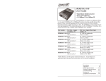
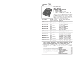
1
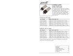
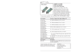
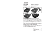
User’s Guide
E-100BTX-FX-05
Stand-Alone Media Converter
• Fast Ethernet
• Copper to Fiber
• 100Base-TX to 100Base-FX
• Extended Temperature
Transition Networks E-100BTX-FX-05 Fast
Ethernet media converters connect 100BaseTX shielded or unshielded twisted-pair copper
cable to 100Base-FX fiber-optic cable. The E100BTX-FX-05 series media converters include both standard temperature models and
extended temperature models.
Standard Temperature Models: 0°C to 50°C (32°F to 122°F)
Part Number
E-100BTX-FX-05
E-100BTX-FX-05(SC)
E-100BTX-FX-05(LC)
E-100BTX-FX-05(MT)
E-100BTX-FX-05(SM)
E-100BTX-FX-05(SMLC)
E-100BTX-FX-05(LH)
E-100BTX-FX-05(XL)
E-100BTX-FX-05(LW)
E-100BTX-FX-05(XLW)
Port One - Copper
100Base-TX
RJ-45
100 m (328 ft)*
RJ-45
100 m (328 ft)*
RJ-45
100 m (328 ft)*
RJ-45
100 m (328 ft)*
RJ-45
100 m (328 ft)*
RJ-45
100 m (328 ft)*
RJ-45
100 m (328 ft)*
RJ-45
100 m (328 ft)*
RJ-45
100 m (328 ft)*
Port Two - Duplex Fiber100Base-FX
ST, 1300 nm multimode
2 km (1.2 miles)*
SC, 1300 nm multimode
2 km (1.2 miles)*
LC, 1300 nm multimode
2 km (1.2 miles)*
MT-RJ, 1300 nm multimode
2 km (1.2 miles)*
SC, 1310 nm single mode
20 km (12.4 miles)*
LC, 1310 nm single mode
20 km (12.4 miles)*
SC, 1310 nm single mode
40 km (24.9 miles)*
SC, 1310 nm single mode
60 km (37.3 miles)*
SC, 1550 nm single mode
80 km (49.7 miles)*
RJ-45
100 m (328 ft)*
SC, 1550 nm single mode
120 km (74.56 miles)*
* Typical maximum cable distance. Actual
distance is dependent upon the physical
characteristics of the network installation.
Installation . . . . . . . . . . . . . . . . . . . . .3
Operation . . . . . . . . . . . . . . . . . . . . .6
Cable Specifications . . . . . . . . . . . . . .8
Technical Specifications . . . . . . . . . .11
Troubleshooting . . . . . . . . . . . . . . .12
Contact Us . . . . . . . . . . . . . . . . . . .14
Compliance Information . . . . . . . . .15
E-100BTX-FX-05
The media converters with the “HT” extension in the part number can be used in an
extended temperature environment from -25°C to 65°C (-13°F to 149°F).
Part Number
Port One - Copper Port Two - Duplex Fiber100Base-TX
100Base-FX
E-100BTX-FX-05(HT)
RJ-45
ST, 1300 nm multimode
100 m (328 ft)*
2 km (1.2 miles)*
E-100BTX-FX-05(SCHT)
RJ-45
SC, 1300 nm multimode
100 m (328 ft)*
2 km (1.2 miles)*
E-100BTX-FX-05(SMHT)
RJ-45
SC, 1310 nm single mode
100 m (328 ft)*
20 km (12.4 miles)*
E-100BTX-FX-05(LHHT)
RJ-45
SC, 1310 nm single mode
100 m (328 ft)*
40 km (24.9 miles)*
E-100BTX-FX-05(XLHT)
E-100BTX-FX-05(LWHT)
E-100BTX-FX-05(100HT)**
E-100BTX-FX-05(101HT)**
RJ-45
100 m (328 ft)*
RJ-45
100 m (328 ft)*
RJ-45
100 m (328 ft)*
SC, 1310 nm single mode
60 km (37.3 miles)*
SC, 1550 nm single mode
80 km (49.7 miles)*
SC, 1310Tx/1550Rx nm single
mode
20 km (12.4 miles)*
RJ-45
100 m (328 ft)*
SC, 1550Tx/1310Rx nm single
mode
20 km (12.4 miles)*
**E-100BTX-FX-05(100/101HT) are installed in pairs.
Installation
CAUTION: Wear a grounding device and observe electrostatic discharge
precautions when setting the 4-position DIP switch and jumpers. Failure to observe
this caution could result in failure of the media converter.
4-position switch
The 4-position DIP switch is
located on the side of the media
converter. Use a small flat-blade
screwdriver or a similar tool to
set the recessed switches.
Auto-Negotiation (up=Enable)
Pause (up=Enable)
Link Pass-Through (up=Enable)
Far End Fault
(up=Enable)
1 2 3 4
1. Auto-Negotiation
up
Enables Auto-Negotiation for the copper connection
down Disables Auto-Negotiation for the copper connection
2. Pause Control
up
Enabled
down Disabled
3. Link Pass-Through
up
Enabled
down Disabled
4. Far-End Fault
up
Enabled
down Disabled
Accessories sold separately
Part Number
Description
SPS-1872-SA
Optional External Power Supply; 18-72VDC Stand-Alone Wide-Input;
Output: 12.6VDC, 1.0 A
SPS-1872-CC
Optional External Power Supply; 18-72VDC Piggy-Back Wide-Input;
Output: 12.6VDC, 1.0 A
E-MCR-05
12-Slot Media Converter Rack (includes universal internal power supply)
17 x 15 x 5 in. (432 x 381 x 127 mm)
WMBL
WMBV
WMBD
Optional Wall Mount Brackets; 4.0 in. (102 mm)
Optional Vertical Mount Bracket; 5.0 in. (127 mm)
Optional DIN Rail Mount Bracket; 5.0 in. (127 mm)
WMBD-FS
Optional DIN Rail Mount Bracket (flat, small); 3.1in. (79 mm)
2
24-hour Technical Support: 1-800-260-1312 – International: 00-1-952-941-7600
[email protected] – Click the “Transition Now” link for a live Web chat.
3
E-100BTX-FX-05
Installation — Continued
AutoCross Jumpers
Installation — Continued
Installing the fiber cable
The AutoCross feature allows either straight-through (MDI) or crossover
(MDI-X) cables to be used when connecting to devices such as hubs,
transceivers, or network interface cards (NICs). AutoCross determines the
characteristics of the cable connection and automatically configures the unit to link
up, regardless of the cable configuration.
1.
High-temperature board, J3, 3-Pin header settings:
1. Orient the board as shown in the photo.
2. Position the jumper as illustrated below the photo.
3.
2.
Locate a 100Base-FX compliant fiber cable with male, two-stranded TX to
RX connectors installed at both ends.
Connect the fiber cables to the media converter as described:
•
Connect the male TX cable connector to the female TX port.
•
Connect the male RX cable connector to the female RX port.
Connect the fiber cables to the other device (another media converter, hub,
etc.) as described:
•
Connect the male TX cable connector to the female RX port.
•
Connect the male RX cable connector to the female TX port.
High Temperature Device
SW1(4-Position)
Connect fiber cable
to media converter
as shown.
J3 AutoCross 3-Pin
Header
AutoCross 3-Pin Header
set to Enabled
J3
Connect fiber cable
to other device
(media converter,
hub, etc.) as shown
RX
RX
TX
Enable AutoCross
J3
TX
Disable AutoCross
Standard temperature board, J1, 3-Pin header settings:
1. Orient the board as shown in the photo.
2. Position the jumper as illustrated below.
Installing the copper cable
1.
2.
J1 AutoCross 3-Pin
Header
AC = AutoCross
Enabled
J1
3.
Locate a 100Base-TX compliant copper cables with male, RJ-45 connectors
installed at both ends.
Connect the RJ-45 connector at one end of the cable to the RJ-45 port on
the media converter.
Connect the RJ-45 connector at the other end of the cable to the RJ-45 port
on the other device (switch, workstation, etc.).
J1
AC = AutoCross
Disabled
RJ-45 port
on the media
converter
4
24-hour Technical Support: 1-800-260-1312 – International: 00-1-952-941-7600
RJ-45 port
on the other device
(switch, work station, etc.)
[email protected] – Click the “Transition Now” link for a live Web chat.
5
E-100BTX-FX-05
Installation — Continued
Operation — Continued
Powering the media converter
AC
1.
2.
3.
Install the power cord barrel connector into the back of the media converter.
Connect the power adapter plug into AC power.
Verify that the media converter is powered up by observing the illuminated
power indicator LED.
Pause control
The Pause feature can improve network performance by allowing one end of the
link to signal the other to discontinue frame transmission for a set period of time
to relieve buffer congestion.
Note:
DC
Consult user guide 33266 for information on the SPS-1872-xx DC external power
supply.
If the Pause feature is available on ALL network devices attached to the
media converter(s), enable the Pause feature on the media converter(s);
otherwise, disable the Pause feature.
Link Pass-Through
Operation
Status LEDs
Use the status LEDs to monitor the E-100BTX-FX-05 media converter operation
in the network:
Power
(Power)
On = Connected to external AC power.
SDF
(Signal Detect/Fiber)
On = Fiber link is detected.
SDC
(Signal Detect/Copper)
On = Copper link is detected.
RXC
(Receive/Copper)
Flashing = A signal is being received on the
copper link.
(Receive/Fiber)
Flashing = A signal is being received on the
fiber link.
RXF
The Link Pass-Through feature allows the media converter to monitor both the
fiber and copper RX (receive) ports for loss of signal. In the event of a loss of an RX
signal (1), the media converter will automatically disable the TX (transmit) signal
(2), thus, “passing through” the link loss (3). The far-end device is automatically
notified of the link loss (4), which prevents the loss of valuable data unknowingly
transmitted over an invalid link.
local converter sends a
loss signal over the fiber link
Near-End
Device
Local
Media
Converter
1
original fault on the
Ethernet copper link
Remote
Media
Converter
2
4
3
Far-End
Device
remote converter disables
the Ethernet copper link
fiber link is still valid
Far-End Fault
When a fault occurs on an incoming fiber link (1), the media converter transmits a
Far-End Fault signal on the outgoing fiber link (2). In addition, the Far-End Fault
signal also activates the Link Pass-Through, which in turn disables the link on the
copper portion of the network (3) and (4).
original fault
on the fiber link
Auto-Negotiation
When the Auto-Negotiation feature is activated, the media converter configures
itself to achieve the best possible mode of operation over a link, automatically. The
media converter broadcasts its speed (100 Mb/s) and duplex capabilities (either fullor half-duplex) and negotiates the best mode of operation between the two devices.
6
24-hour Technical Support: 1-800-260-1312 – International: 00-1-952-941-7600
Near-End
Device
4
Media
Converter A
media converter A
disables the copper link
1
2
Far-End Fault
signal is sent
Media
Converter B
3
Far-End
Device
media converter B
disables the copper link
[email protected] – Click the “Transition Now” link for a live Web chat.
7
E-100BTX-FX-05
Cable Specifications — continued
Cable Specifications
The physical characteristics must meet or exceed IEEE 802.3™ specifications.
Fiber cable
Bit Error Rate:
Single mode fiber (recommended):
Multimode fiber (recommended):
Multimode fiber (optional):
<10-9
9 µm
62.5/125 µm
100/140, 85/140, 50/125 µm
Extended temperature models
8
E-100BTX-FX-05(HT)
Fiber Optic Transmitter Power:
Fiber Optic Receiver Sensitivity:
Link Budget:
1300 nm multimode
min: -19.0 dBm
max: -14.0 dBm
min: -30.0 dBm
max: -14.0 dBm
11.0 dbm
E-100BTX-FX-05(SCHT)
Fiber Optic Transmitter Power:
Fiber Optic Receiver Sensitivity:
Link Budget:
1300 nm multimode
min: -19.0 dBm
max: -14.0 dBm
min: -30.0 dBm
max: -14.0 dBm
11.0 dbm
E-100BTX-FX-05(SMHT)
Fiber-optic Transmitter Power:
Fiber-optic Receiver Sensitivity:
Link Budget:
1310 nm single mode
min: -15.0 dBm
max: -8.0 dBm
min: -31.0 dBm
max: -8.0 dBm
16.0 dbm
E-100BTX-FX-05(LHHT)
Fiber-optic Transmitter Power:
Fiber-optic Receiver Sensitivity:
Link Budget:
1310 nm single mode
min: -8.0 dBm
max: -2.0 dBm
min: -34.0 dBm
max: -7.0 dBm
26.0 dbm
E-100BTX-FX-05(XLHT)
Fiber-optic Transmitter Power:
Fiber-optic Receiver Sensitivity:
Link Budget:
1310 nm single mode
min: -5.0 dBm
max: 0.0 dBm
min: -38.0 dBm
max: -8.0 dBm
33.0 dbm
E-100BTX-FX-05(LWHT)
Fiber-optic Transmitter Power:
Fiber-optic Receiver Sensitivity:
Link Budget:
1550 nm single mode
min: -5.0 dBm
max: 0.0 dBm
min: -34.0 dBm
max: -7.0 dBm
29.0 dbm
E-100BTX-FX-05(100HT)
E-100BTX-FX-05(101HT)
Fiber-optic Transmitter Power:
Fiber-optic Receiver Sensitivity:
Link Budget:
1310Tx/1550Rx nm single mode
1550Tx/1310Rx nm single mode
min: -14.0 dBm
max:-8.0 dBm
min: -33.0 dBm
max: -3.0 dBm
19.0 dbm
24-hour Technical Support: 1-800-260-1312 – International: 00-1-952-941-7600
Standard models
E-100BTX-FX-05
Fiber Optic Transmitter Power:
Fiber Optic Receiver Sensitivity:
Link Budget:
1300 nm multimode
min: -19.0 dBm
max: -14.0 dBm
min: -30.0 dBm
max: -14.0 dBm
11.0 dbm
E-100BTX-FX-05(SC) & (LC)
Fiber Optic Transmitter Power:
Fiber Optic Receiver Sensitivity:
Link Budget:
1300 nm multimode
min: -19.0 dBm
max: -14.0 dBm
min: -30.0 dBm
max: -14.0 dBm
11.0 dbm
E-100BTX-FX-05(MT)
Fiber Optic Transmitter Power:
Fiber Optic Receiver Sensitivity:
Link Budget:
1300 nm multimode
min: -19.0 dBm
max: -14.0 dBm
min: -33.5 dBm
max: -14.0 dBm
14.5 dbm
E-100BTX-FX-05(SM)
Fiber-optic Transmitter Power:
Fiber-optic Receiver Sensitivity:
Link Budget:
1310 nm single mode
min: -15.0 dBm
max: -8.0 dBm
min: -31.0 dBm
max: -8.0 dBm
16.0 dbm
E-100BTX-FX-05(SMLC)
Fiber-optic Transmitter Power:
Fiber-optic Receiver Sensitivity:
Link Budget:
1310 nm single mode
min: -15.2 dBm
max: -8.0 dBm
min: -32.5 dBm
max: -3.0 dBm
17.3 dbm
E-100BTX-FX-05(LH)
Fiber-optic Transmitter Power:
Fiber-optic Receiver Sensitivity:
Link Budget:
1310 nm single mode
min: -8.0 dBm
max: -2.0 dBm
min: -34.0 dBm
max: -7.0 dBm
26.0 dbm
E-100BTX-FX-05(XL)
E-100BTX-FX-05(LW)
Fiber-optic Transmitter Power:
Fiber-optic Receiver Sensitivity:
Link Budget:
1310 nm single mode
1550 nm single mode
min: -5.0 dBm
max: 0.0 dBm
min: -34.0 dBm
max: -7.0 dBm
29.0 dbm
E-100BTX-FX-05(XLW)
Fiber-optic Transmitter Power:
Fiber-optic Receiver Sensitivity:
Link Budget:
1550 nm single mode
min: 0.0 dBm
max: 5.0 dBm
min: -36.0 dBm
max: -3.0 dBm
36.0 dbm
The fiber optic transmitters on this device meet Class I Laser safety
requirements per IEC-825/CDRH standards and comply with 21 CFR1040.10
and 21CFR1040.11.
[email protected] – Click the “Transition Now” link for a live Web chat.
9
E-100BTX-FX-05
Cable Specifications — Continued
Copper cable
Category 5: (minimum requirement)
Gauge:
Attenuation:
Maximum Cable Distance:
Technical Specifications
For use with Transition Networks Model E-100BTX-FX-05(xxxx) or equivalent
Data rate:
24 to 22 AWG
22.0 db /100m @ 100 MHz
100 meters
• Straight-through or crossover cable may be used.
• Shielded twisted-pair (STP) or unshielded twisted-pair (UTP) may be used
• Pins 1&2 and 3&6 are the two active pairs in an Ethernet network .
• RJ-45 Pin-out: Pin 1 = TD+, Pin 2 = TD-, Pin 3 = RD+, Pin 6 = RD• Use only dedicated wire pairs for the active pins:
(e.g., blue/white & white/blue, orange/white & white/orange, etc.)
• Do not use flat or silver satin wire.
Straight-Through Cable
Crossover Cable
Twisted Pair #1
Twisted Pair #1
Twisted Pair #2
Twisted Pair #2
100 Mb/s
Dimensions:
4.75" x 3.0" x 1.0" (119mm x 76mm x 25mm)
Weight:
6 oz. (181 g) approximately
MTBF:
Greater than 41,680 hours (MIL-HDBK-217F)
Greater than 114,580 hours (Bellcore7 V5.0)
Power supply
DC output:
(standard temperature)
12 VDC, 0.5 A (minimum)
(extended temperature)
9 VDC, 1.0 A (minimum)
minimum output regulation: 5%
Environment:
Tmra* (standard temp):
Storage Temperature:
0°C to 50°C (32 to 122°F)
-15°C to 65°C (5 to 149°F)
Tmra* (extended temp):
Storage Temperature:
-25°C to 65°C (-13 to 149°F)
-25°C to 65°C (5 to 149°F)
Humidity:
10% – 90%, non-condensing
Warranty:
Lifetime
*Manufacturer’s rated ambient temperature.
CAUTION: Visible and invisible laser radiation when open. Do not stare into beam
or view directly with optical instruments.
CAUTION: Use of controls, adjustments or the performance of procedures other
than those specified herein may result in hazardous radiation exposure.
CAUTION: Copper based media ports, e.g., Twisted Pair (TP) Ethernet, USB, RS232,
RS422, RS485, DS1, DS3, Video Coax, etc., are intended to be connected to intrabuilding (inside plant) link segments that are not subject to lightening transients or
power faults. Copper based media ports, e.g., Twisted Pair (TP) Ethernet, USB,
RS232, RS422, RS485, DS1, DS3, Video Coax, etc., are NOT to be connected to
inter-building (outside plant) link segments that are subject to lightening transients or
power faults. Failure to observe this caution could result in damage to equipment.
10
24-hour Technical Support: 1-800-260-1312 – International: 00-1-952-941-7600
[email protected] – Click the “Transition Now” link for a live Web chat.
11
E-100BTX-FX-05
Troubleshooting
If the media converter fails, isolate and correct the fault by determining the answers
to the following questions and then taking the indicated action:
Declaration of Conformity
Name of Mfg:
Model Number(s):
Note:
1.
2.
DIP switch positions 3 and 4 must be DOWN before starting the
troubleshooting process.
Is the Power LED illuminated?
NO
•
Is the power adapter the correct model (check I/O voltage and Hz)?
•
Verify the voltage and frequency of the AC outlet?
•
Are the power barrel connector and wall plug of the power adapter
properly inserted in the media converter and plugged into the AC wall
outlet ?
•
Contact Tech Support: 800-260-1312, Int’l: 00-1-952-941-7600.
YES
•
Proceed to step 2.
Is the SDC (signal detect/copper) LED illuminated?
NO
•
Check the twisted-pair cables for proper connection.
•
Contact Tech Support: 800-260-1312, Int’l: 00-1-952-941-7600.
YES
•
Proceed to step 3.
3.
Is the SDF LED (signal detect/fiber) illuminated?
NO
•
Check the fiber cables for proper connection.
•
Verify that the TX and RX cables on the media converter are connected to
the RX and TX ports, respectively, on the other device.
•
Contact Tech Support: 800-260-1312, Int’l: 00-1-952-941-7600.
YES
•
Proceed to step 4.
4.
Is the RXC (receive/copper) LED flashing?
NO
•
If there is no activity on the UTP/STP port, proceed to step 5.
•
If there is activity on the UTP/STP port, disconnect and reconnect the
twisted-pair cable to restart the initialization process.
•
Contact Tech Support: 800-260-1312, Int’l: 00-1-952-941-7600.
YES
•
Proceed to step 5.
5.
Is the RXF (receive/fiber) LED flashing?
NO
•
If there is no activity on the fiber port, contact Tech Support.
•
If there is activity on the fiber port, disconnect and reconnect the fiber cable
to restart the initialization process.
•
Contact Tech Support: 800-260-1312, Int’l: 00-1-952-941-7600.
YES
•
Contact Tech Support: 800-260-1312, Int’l: 00-1-952-941-7600.
12
24-hour Technical Support: 1-800-260-1312 – International: 00-1-952-941-7600
Transition Networks
10900 Red Circle Drive, Minnetonka MN 55343, U.S.A.
E-100BTX-FX-05, E-100BTX-FX-05(SC),
E-100BTX-FX-05(LC), E-100BTX-FX-05(MT),
E-100BTX-FX-05(SM), E-100BTX-FX-05(SMLC),
E-100BTX-FX-05(LH), E-100BTX-FX-05(XL),
E-100BTX-FX-05(LW), E-100BTX-FX-05(XLW)
E-100BTX-FX-05(SMHT), E-100BTX-FX-05(HT),
E-100BTX-FX-05(LHHT), E-100BTX-FX-05(XLHT),
E-100BTX-FX-05(LWHT), E-100BTX-FX-05(SCHT)
E-100BTX-FX-05(100HT), E-100BTX-FX-05(101HT)
Purpose: To declare that the E-100BTX-FX-05(xxxx) to which this declaration
refers is in compliance with the following directive(s) and standard(s):
EMC Directive 2004/108/EC; EN 55022:2006+A1:2007 Class A;
EN55024:1998+A1:2001+A2:2003; EN6100-2-3; EN6100-3-3; CFR Title 47 Part 15
Subpart B Class A. Low Voltage Directive: 2006/95/EC; IEC 60950-1:2005; CFR Title
21 Section 1040.10 Class I; UL Listed; C-UL Listed; CE Mark
I, the undersigned, hereby declare that the model number(s) listed in this declaration
of conformity are in compliance with the directive(s) and standard(s) herein.
Stephen Anderson, Vice-President of Engineering
February, 2010_____
Date
[email protected] – Click the “Transition Now” link for a live Web chat.
13
E-100BTX-FX-05
Contact Us
Compliance Information
Technical support
Technical support is available 24 hours a day.
US and Canada:
1-800-260-1312
International:
00-1-952-941-7600
FCC regulations
Transition now
Chat live via the Web with Transition Networks Technical Support.
Log onto www.transition.com and click the Tech Support/Transition Now link.
Web-based seminars
Transition Networks provides seminars via live web-based training.
Log onto www.transition.com and click the Learning Center link.
E-Mail
Ask a question anytime by sending an e-mail to our technical support staff.
[email protected]
Address
Transition Networks
10900 Red Circle Drive, Minnetonka, MN 55343, U.S.A.
telephone:
952-941-7600
toll free:
800-526-9267
fax:
952-941-2322
This equipment has been tested and found to comply with the limits for a Class A digital device,
pursuant to part 15 of the FCC rules. These limits are designed to provide reasonable protection
against harmful interference when the equipment is operated in a commercial environment. This
equipment generates, uses, and can radiate radio frequency energy and, if not installed and used in
accordance with the instruction manual, may cause harmful interference to radio communications.
Operation of this equipment in a residential area is likely to cause harmful interference, in which
case the user will be required to correct the interference at the user's own expense.
Canadian regulations
This digital apparatus does not exceed the Class A limits for radio noise for digital apparatus set
out on the radio interference regulations of the Canadian Department of Communications.
Le présent appareil numérique n'émet pas de bruits radioélectriques dépassant les limites
applicables aux appareils numériques de la Class A prescrites dans le Règlement sur le brouillage
radioélectrique édicté par le ministère des Communications du Canada.
European regulations
Warning
This is a Class A product. In a domestic environment this product may cause radio interference in
which case the user may be required to take adequate measures.
Achtung !
Dieses ist ein Gerät der Funkstörgrenzwertklasse A. In Wohnbereichen können bei Betrieb dieses
Gerätes Rundfunkstörungen auftreten. In diesem Fäll ist der Benutzer für Gegenmaßnahmen
verantwortlich.
Attention !
Ceci est un produit de Classe A. Dans un environment domestique, ce produit risque de créer des
interférences radioélectriques, il appartiendra alors à l'utilsateur de prende les measures
spécifiques appropriées.
In accordance with European Union Directive 2002/96/EC of the European Parliament
and of the Council of 27 January 2003, Transition Networks will accept post usage
returns of this product for proper disposal. The contact information for this activity can
be found in the 'Contact Us' portion of this document.
CAUTION: RJ connectors are NOT INTENDED FOR CONNECTION TO THE
PUBLIC TELEPHONE NETWORK. Failure to observe this caution could result in
damage to the public telephone network.
Der Anschluss dieses Gerätes an ein öffentlickes Telekommunikationsnetz in den EGMitgliedstaaten verstösst gegen die jeweligen einzelstaatlichen Gesetze zur Anwendung der
Richtlinie 91/263/EWG zur Angleichung der Rechtsvorschriften der Mitgliedstaaten über
Telekommunikationsendeinrichtungen einschliesslich der gegenseitigen Anerkennung ihrer
Konformität.
14
24-hour Technical Support: 1-800-260-1312 – International: 00-1-952-941-7600
[email protected] – Click the “Transition Now” link for a live Web chat.
15
Trademark notice
All trademarks and registered trademarks are the property of their respective owners.
Copyright restrictions
© 2003-2010 Transition Networks.
All rights reserved. No part of this work may be reproduced or used in any form or by
any means - graphic, electronic, or mechanical - without written permission from
Transition Networks.
Printed in the U.S.A.
16
33210.P