1
OWNER’S MANUAL
DATA PROJECTOR
TDP-MT500
SAFETY PRECAUTIONS
The lightning flash with arrowhead symbol, within an equilateral triangle, is intended to alert the user to the presence of uninsulated "dangerous voltage"
within the product's enclosure that may be of sufficient magnitude to constitute
a risk of electric shock to persons.
The exclamation point within an equilateral triangle is intended to alert the user
to the presence of important operating and maintenance (servicing) instructions
in the literature accompanying the appliance.
WARNING:
USA only
WARNING:
TO REDUCE THE RISK OF FIRE OR ELECTRIC SHOCK, DO NOT EXPOSE THIS APPLIANCE TO RAIN OR MOISTURE. DANGEROUS HIGH
VOLTAGES ARE PRESENT INSIDE THE ENCLOSURE. DO NOT OPEN
THE CABINET. REFER SERVICING TO QUALIFIED PERSONNEL ONLY.
Handling the cord on this product or cords associated with accessories sold
with this product, will expose you to lead, a chemical known to the State of
California to cause birth defects or other reproductive harm. Wash hands after
handling.
FCC NOTICE: This equipment has been tested and found to comply with the limits for a
Class B digital device, pursuant to part 15 of the FCC Rules. These limits are
designed to provide reasonable protection against harmful interference in a
residential installation. This equipment generates, uses and can radiate radio
frequency energy and, if not installed and used in accordance with the instructions, may cause harmful interference to radio communications. However, there is no guarantee that interference will not occur in a particular
installation.
If this equipment does cause harmful interference to radio or television reception, which can be determined by turning the equipment off and on, the user is
encouraged to try to correct the interference by one or more of the following
measures:
- Reorient or relocate the receiving antenna.
- Increase the separation between the equipment and receiver.
- Connect the equipment into an outlet on a circuit different from that to which
the receiver is connected.
- Consult the dealer or an experienced radio/TV technician for help.
WARNING:
Changes or modifications made to this equipment, not expressly approved by
Toshiba, or parties authorized by Toshiba, could void the userís authority to
operate the equipment.
CANADA only
Notice:
This Class B digital apparatus complies with Canadian ICES-003.
Cet appareil numérique de la classe B est conforme à la norme NMB-003 du
Canada.
2
IMPORTANT SAFETY INSTRUCTIONS
CAUTION:
PLEASE READ AND OBSERVE ALL WARNINGS AND INSTRUCTIONS GIVEN
IN THIS OWNER'S MANUAL AND THOSE MARKED ON THE UNIT. RETAIN
THIS BOOKLET FOR FUTURE REFERENCE.
This set has been designed and manufactured to assure personal safety. Improper use can
result in electric shock or fire hazard. The safeguards incorporated in this unit will protect you if
you observe the following procedures for installation, use and servicing. This unit is fully transistorized and does not contain any parts that can be repaired by the user.
1.
Read Owner's Manual
3.
After unpacking this product, read
the owner's manual carefully, and
follow all the operating and other
instructions.
2.
Power Sources
This product should be operated only
from the type of power source indicated
on the marking label. If you are not sure
of the type of power supply to your home,
consult your product dealer or local
power company.
For products intended to operate from
battery power, or other sources, refer to
the operating instructions.
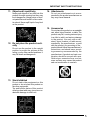
Source of Light
Do not look into the lens while the lamp
is on. The strong light from the lamp may
cause damage to your eyes or sight.
4.
Ventilation
Openings in the cabinet are provided for
ventilation and to ensure reliable operation of the product and to protect it from
overheating, and these openings must
not be blocked or covered.
The openings should never be blocked
by placing the product on a bed, sofa,
rug or other similar surface. This product should not be placed in a built-in installation such as a bookcase or rack
unless proper ventilation is provided or
the manufacturer's instructions have
been adhered to.
3
IMPORTANT SAFETY INSTRUCTIONS
5.
Heat
8.
The product should be situated away
from heat sources such as radiators,
heat registers, stoves, or other products
(including amplifiers) that produce heat.
6.
Power-supply cords should be routed so
that they are not likely to be walked on
or pinched by items placed upon or
against them, paying particular attention
to cords at plugs, convenience receptacles, and the point where they exit from
the product.
Water and Moisture
Do not use this product near water.
- for example, near a bath tub, wash
bowl, kitchen sink, or laundry tub; in a
wet basement; or near a swimming pool
and the like.
7.
Power-Cord Protection
9.
Overloading
Do not overload wall outlets; extension
cords, or integral convenience receptacles as this can result in a risk of fire
or electric shock.
Cleaning
Unplug this product from the wall outlet
before cleaning. Do not use liquid cleaners or aerosol cleaners.
Use a soft cloth for cleaning.
10. Lightning storms
For added protection for this product
during storm, or when it is left unattended and unused for long periods of
time, unplug it from the wall outlet. This
will prevent damage to the product due
to lightning and power-line surges.
4
IMPORTANT SAFETY INSTRUCTIONS
11. Object and Liquid Entry
Never push objects of any kind into this
product through openings as they may
touch dangerous voltage points or shortout parts that could result in a fire or electric shock. Never spill liquid of any kind
on the product.
14. Attachments
Do not use attachments not recommended by the product manufacturer as
they may cause hazards.
15. Accessories
12. Do not place the product vertically
Do not use the product in the upright
position to project the pictures at the
ceiling, or any other vertical positions. It
may fall down and dangerous.
Do not place this product on an unstable
cart, stand, tripod, bracket, or table. The
product may fall, causing serious injury
to a child or adult, and serious damage
to the product. Use only with a cart,
stand, tripod, bracket, or table recommended by the manufacturer, or sold
with the product. Any mounting of the
product should follow the manufacturer's
instructions, and should use a mounting accessory recommended by the
manufacturer. A product and cart combination should be moved with care.
Quick stops, excessive force, and uneven surfaces may cause the product
and cart combination to overturn.
13. Stack Inhibited
Do not stack other equipment on this
product or do not place this product on
the other equipment.
Top and bottom plates of this product
develops heat and may give some undesirable damage to other unit.
5
IMPORTANT SAFETY INSTRUCTIONS
16. Damage Requiring Service
Unplug this product from the wall outlet
and refer servicing to qualified service
personnel under the following conditions:
a) When the power-supply cord or plug is
damaged.
b) If liquid has been spilled, or objects have
fallen into the product.
c) If the product has been exposed to rain
or water.
d) If the product does not operate normally
by following the operating instructions.
Adjust only those controls that are covered by the operating instructions as an
improper adjustment of other controls
may result in damage and will often require extensive work by a qualified technician to restore the product to its normal operation.
e) If the product has been dropped or damaged in any way.
f) When the product exhibits a distinct
change in performance - this indicates
a need for service.
17. If glass components, including
lens and lamp, should break,
contact your dealer for repair
service.
This product incorporates glass components, including a lens and a lamp. If
such parts should break, please handle
with care to avoid injury and contact your
dealer for repair service. The broken
pieces of glass may cause to injury. In
the unlikely event of the lamp rupturing,
thoroughly clean the area around the
projector and discard any edible items
placed in that area.
6
18. Servicing
Do not attempt to service this product
yourself as opening or removing covers
may expose you to dangerous voltage
or other hazards. Refer all servicing to
qualified service personnel.
19. Replacement Parts
When replacement parts are required,
be sure the service technician has used
replacement parts specified by the
manufacturer or have the same characteristics as the original part. Unauthorized substitutions may result in fire,
electric shock, or other hazards.
(Replacement of the lamp only should
be made by users.)
20. Safety Check
Upon completion of any service or repairs to this product, ask the service
technician to perform safety checks to
determine that the product is in proper
operating condition.
IMPORTANT SAFETY INSTRUCTIONS
21. Do not leave thermal-paper
documents or easily deformed
items on top of the unit or near
the air exhaust.
The heat from the unit could erase the
information on the thermal paper, or
cause deformation or warping.
Also, when you touch a metal object put
near the air exhaust, a burn may be
caused.
22. Unplug the power plug after
the projector is finished to
use.
Turn off POWER button to bring the projector into its standby state with the lightsource lamp off. Then, wait about 2 minutes and turn off the main power switch,
and be sure to unplug the power plug
for safety.Wait about 2 minutes in
standby state, because during this time
the intake/exhaust fan is operating to
cool down the light-source lamp. Turning off the main power switch or unplugging the power plug immediately
after use may bring the projector into
failure.
7
POWER SUPPLY CORD SELECTION
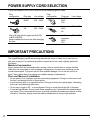
If your line voltage is 220 to 240V, use one of the following types of cable.
Plug
configuration
Plug type
Line voltage
EURO
220 – 240V
UK
Plug
configuration
220 – 240V
Use a 5A fuse which is approved by ASTA
or BSI to BSI362.
Always replace the fuse cover after changing
the fuse.
Plug type
Australian
240V
10A
Line voltage
Switzerland 200 – 240V
240V
6A
North
American
240V
15A
200 – 240V
IMPORTANT PRECAUTIONS
Save Original Packing Materials
The original shipping carton and packing materials will come in handy if you ever have to
ship your projector. For maximum protection, repack the set as it was originally packed at
the factory.
Moisture Condensation
Never operate this unit immediately after moving it from a cold location to a warm location.
When the unit is exposed to such a change in temperature, moisture may condense on the
crucial internal parts. To prevent the unit from possible damage, do not use the unit for at
least 2 hours when there is an extreme or sudden change in temperature.
Place and Manner of Installation
• Do not place in hot locations, such as near heating equipment. Doing so could cause malfunction, and shorten the life of the projector.
• Avoid locations with oil or cigarette smoke. Doing so will dirty the optical parts, shortening
their lives, and darkening the screen.
• Do not use in angle of 20∞ or more degrees. Doing so could shorten the life of the lamp.
• If used at high altitudes, the unit could cease operation even if used within the rated temperature range. This is because the thinner air at high altitudes decreases the internal cooling
efficiency. Therefore, please lower the ambient temperature if using at high altitudes.
8
IMPORTANT PRECAUTIONS
Avoid Volatile Liquid
Do not use volatile liquids, such as an insect spray, near the unit. Do not leave rubber or
plastic products touching the unit for a long time. They will leave marks on the finish.
If cleaning with a chemically saturated cloth, be sure to follow the product’s precautions.
In the spaces provided below, record the Model and Serial No. located at the bottom of your
projector.
Model No.
Serial No.
Retain this information for future reference.
DECLARATION OF CONFORMITY
TRADE NAME: DLP DATA PROJECTOR
MODEL NAME: TDP-MT500
RESPONSIBLE PARTY: TOSHIBA AMERICA INFORMATION SYSTEMS, INC.
9740 Irvine Blvd., Irvine, CA 92618-1697 U.S.A
Phone: (949) 583-3000
This device complies with part 15 of the FCC Rules.
Operation is subject to the following two conditions:
(1) this device may not cause harmful interference, and
(2) this device must accept any interference received, including interference that may cause
undesired operation.
9
TABLE OF CONTENTS
PREPARATION
Checking accessories ............................................................................................................................................................ 11
Inserting the dry batteries into the remote controller ......................................................................................................... 11
Name and function of operational parts of the projector ....................................................................................................12
How to use remote controller ................................................................................................................................................13
Operational range of remote controller ............................................................................................................................... 14
SETTING UP
Setting up screen ....................................................................................................................................................................15
Basic setup ..............................................................................................................................................................................15
Screen size and Projection distance .................................................................................................................................... 16
VIWING VIDEO IMAGES
A. Connecting the projector to video equipment
B. Plugging power cord ..........................................................................................................................................................20
C. Making projection ...............................................................................................................................................................21
D. On setting ASPECT (Image angle) ................................................................................................................................... 23
E. Connecting this projector with a computer .................................................................................................................... 24
F. Plugging power cord ..........................................................................................................................................................24
VIWING COMPUTER IMAGES .............................................................................................. 24
A. Connecting the projector with a computer ..................................................................................................................... 24
B. Plugging power cord ..........................................................................................................................................................24
C. Making projection ...............................................................................................................................................................25
SETTING WITH MENUS
Menu construction ..................................................................................................................................................................27
How to make menu setting: ...................................................................................................................................................28
Items that can be set with menus ......................................................................................................................................... 29
REPLACING THE LAMP / CLEANING THE PROJECTOR .................................................. 34
TROUBLESHOOTING ............................................................................................................ 36
INDICATORS .......................................................................................................................... 38
WHEN ASKING INSTALLATION WORK ............................................................................... 39
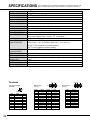
SPECIFICATIONS .................................................................................................................. 40
10
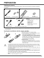
PREPARATION
Checking accessories
The following accessories are provided with this projector. Check to be sure that all the accessories are packed in
the package.)
Power supply parts
Power cable
Remote controller parts
Personal computer parts
Video parts
DVI
Mini DIN 8P
RS-232C cable
Size-AAA
dry batteries (two)
Others
•
•
•
•
•
•
Mini D-SUB 15P
D-SUB 9P
•
Remote controller
Conversion adaptor
Lens cap (Attached to the main body)
Soft carrying case
Operation manual
Regular user card
Warranty card
Remote controller photo-sensor
protection sticker
Mini D-SUB 15P DVI-conversion cable
The attached power cable and conversion adaptor are to be used exclusively for this product. Never use them
for other products.
Inserting the dry batteries into the remote controller
1
3
2
•
•
•
•
•
•
1. Remove the rear lid of the remote controller.
2. Check the polarity (+), (-) of the dry batteries, and set
them correctly inserting their (-) side first.
• If the battery is inserted from the (+) side first, inserting
the (-) side is difficult because the coil spring end hits on
the battery side. If the battery is forced to insert in this
way, the outer label of the battery may get ripped and it
may cause short-circuit and heating.
3. Attach the rear lid.
• Use two size-AAA dry batteries (RO3).
• Exchange the two batteries to new ones if the distance
that allows the remote controller to operate becomes
shorter than usual.
Correctly treat the batteries after thoroughly reading "On treating the batteries" described on Page 7.
If the batteries are treated incorrectly, they may cause fire or peripheral contamination due to leakage
of the liquid, heating, or burst. (Read the cautions indicated on the battery, too.)
This projector is designed as plug-in equipment. There must be an easily accessible power outlet near
the installed projector.
Use the attached power cord with this projector. Using any other power cord than specified could
cause electromagnetic interference to radio or television broadcast.
Use the attached mini D-SUB 15pin-DVI conversion cable and RS-232C cable to suppress the interference within the restriction for J55022 class-B apparatus.
Use a DVI shielded cable to suppress the interference within the restriction for J55022 class-B apparatus.
Be sure to connect this projector to a ground.
11
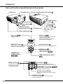
PREPARATION
Name and function of operational parts of the projector
Intake vent
Operation panel
Remote controller photo-sensor (Rear) 10
Angle adjusting
button 11
Terminal panel
Angle adjusting 11
button
Theft-prevention
lock hole 36
Remote controller
photo-sensor (Front) 10
Exhaust vent
Power cable inlet 17
Main power switch
I: Turn-on
O: Turn-off
Angle adjusting foot 11
Focus ring: 18 22
Adjusts focus.
Zoom ring: 18 22
Expands projected picture images when
turned to the right (WIDE).
Contracts projected picture images
when turned to the left (TELE).
TELE
WIDE
MENU/EXIT button: 25
Directional button: 25
Displays menu when pressed.
Erases menu when pressed again.
Used to shift menu item and adjust values.
ENTER button: 25
ENTER
MENU/EXIT
POWER
LAMP indicator 32 34 36
LAMP
TEMP
POWER button /
POWER indicator
18 22 34 36
Used to determine menu item.
TEMP (temperature) indicator
34 36
DVI
VEDEO terminal: 14
Connects to such equipment as
video players that output
composite video signals.
DVI terminal: 15 21
VIDEO
COMPONENT1
Y
Cb/Pb
Cr/Pr
COMPONENT 1, 2 terminals: 14 15 16
COMPONENT2
S-VIDEO
Connects to such equipment as video
equipment with DVI-D terminal and computers.
RS-232C
Connects to such equipment as DVD players
that output chrominance signals.
RS-232C terminal (DIN 8P):
Used mainly for adjustments made by service
personnel.
S-VIDEO terminal: 14
Connects to such equipment as video players that
output S-video signals.
12
PREPARATION
How to use remote controller
Name and function of operational parts of remote controller
POWER ON/OFF
POWER button: 18 22
SOURCE
C1
C2
DVI
D
COMP1
COMP2
DVI-D
S
V
DVI
A
S-VIDEO
VIDEO
DVI-A
16:9
4:3
ZM
16:9
4:3
ZOOM
DYN
REAL
REAL
MEMORY (1, 2, 3) buttons: 27
Set the pre-stored values in the
picture adjustment menu when
pressed.
Selects an input video signal to be
projected.
ASPECT button: 20
Selects size of the video image according to
the video signal to be projected.
DYNAMIC
ASPECT
2
SOURCE button: 18 22
3
ENTER button: 25
1
Used to determine menu item.
Directional button: 25
ENTER
Used to shift menu item and adjust values.
MENU button: 25
MENU
EXIT
EXIT button: 25
Displays the menu in one-level higher
hierarchy when pressed.
Displays menu.
Erases the menu when pressed again.
CNT
CONTRAST BRIGHT
TEM
COLOR
TEMP
COL
TIN
COLOR
TINT
BRI
GAM
SH
GAMMA SHARPNESS
LIGHT
LIGHT
Picture quality adjusting button:
(See below)
LIGH button:
Switches between LIGHT modes of remote controller every time
it is pressed.
If the remote controller button lights up when the LIGHT button
is pressed, the dark-room mode is brought into ON. If it does not
light up, the normal mode is ON.
Dark room mode : All the buttons on the remote controller light
up if any of the buttons is pressed.
Normal mode
: Any of the buttons on the remote controller
does not light up if any of the button is
pressed (Except for LIGHT button).
• The light automatically comes off a while after the remote
controller button is released.
On the picture quality adjusting buttons
When any of the picture quality adjusting button is pressed, its corresponding screen for adjusting the
picture quality appears. Then, adjust the picture quality by pressing % and $ button. The picture quality
adjustment can also be made in the picture quality menu. (See Page 26.)
The following picture quality adjusting buttons are displayed on the menu screen:
CONTRAST ......... Adjusts the contrast of projected picture images. Every time the % button is pressed, the projected image becomes brighter and more vivid. Every time the $ button is pressed, the projected image becomes darker and less vivid.
BRIGHT ................ Adjusts the brightness of projected picture images. Every time the % button is pressed, the
projected image becomes brighter. Every time the $ button is pressed, the projected image
becomes darker.
COLOR ................ Adjust the color thickness of projected picture image. Every time the % button is pressed, the
projected image color becomes thicker. Every time the $ button is pressed, the projected
image color becomes thinner.
TINT ..................... Adjusts the tint of projected picture images. Every time the % button is pressed, the skin color
of projected image becomes more reddish. Every time the $ button is pressed, the skin color
of projected image becomes greenish.
COLOR TEMP ..... Selects one of the preset color temperatures.
GAMMA ................ Selects one of the preset gamma corrections.
SHARPNESS ....... Adjusts the sharpness of projected picture images. Every time the % button is pressed, the
projected picture image becomes sharper. Every time the $ button is pressed, the projected
picture image becomes softer.
13
PREPARATION
Operational range of remote controller
Front of projector
Rear of projector
•
30˚
30˚
30˚
Operate the
remote controller
within a distance
of 10 m from the
projector, pointing
the light beam at
the remote control
photo-sensor
(front or rear) of
the projector.
30˚
•
•
Keep the remote controller photo-sensor
away from the direct sun light or fluorescent lamp light.
Keep the remote controller photo-sensor
at least 2 m apart from fluorescent lamps.
Otherwise, the remote controller may
malfunction.
If there is an inverter-operated fluorescent lamp near the remote controller, the
remote controller operation may become
unstable. On this occasion, stick the attached protection sticker on the photosensor that is closer to the fluorescent
lamp.
When operating the remote controller forwarding the
light beam to projector screen, keep the distance from
the remote controller to the projector via the screen
within about 6m. The operable range of the remote
controller, however, depends on the characteristics of
the screen.
Vertical directions
15˚
15˚
15˚
15˚
Vertical directions (When the projector is suspended from ceiling)
15˚
14
15˚
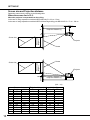
SETTING UP
Setting up screen
Set the screen perpendicular to the projector. If the screen can not be set perpendicularly, adjust the
projection angle of the projector. (See below.)
• Adjust the screen or projector so that the shadow of the projector lens may be projected onto the center of the
screen.
• Do not place the screen where the direct sunlight and illuminating lights come onto the screen. Direct light
illumination onto the screen could whiten the screen surface making the projected picture images bad to see.
Basic setup
Determine the distance from the screen to the projector according to the size of the picture images to be
projected. (See Page 14 and 15.)
Size of projected picture
images (Width)
Screen
A
B
Screen
Projector
•
A=B
As for the locations for the setup, read "Be sure to observe the followings for safety" described on Pages 4 to 7
in advance.
Adjusting projection angle
If a part of the projected picture image lies off the
edge of the screen, adjust the projection height or
the projection angle as follows:
1
2
5. Slowly lift down the projector by pressing the left
and right angle-adjusting buttons while holding the
projector by hands.
• It is also possible to adjust the projection angle by turning the angle adjusting foot (rear) to the lift or right.
If the projected image frame is distorted
to a trapezoid:
1. Lift up the projector up to the desired projection
angle by hands.
• Set the projector within a tilt angle of 15 degrees.
2. Press up the left and right angle adjusting buttons.
3. Release the hands from the angle adjusting buttons and projector.
4
4. By turning the angle adjusting foot (front) to the
left or right, make fine adjustment so that the projected image frame may be in parallel with the
sides of the screen.
When storing the projector:
5
If the screen and the projector are not set perpendicular to each other, the projected image frame becomes trapezoidal.If it is not possible to bring them
into positions perpendicular to each other by any
mechanical adjustments, adjust the value for trapezoidal correction in the setup menu. (See Page 19.)
• If the "trapezoidal correction" is applied, the aspect ratio may not be adjusted correctly in some
cases.
• If the "trapezoidal correction" is applied, the resolution of the projected image will be reduced. Also,
moire fringes on fine-pattern images or drooping
of straight lines in the images will appear. Therefore, try to set the screen and the projector perpendicular to each other as much as possible.
15
SETTING UP
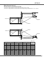
Screen size and Projection distance
Determine screen size by referring to the following table:
Where the screen size is 16: 9
Projection distance (L)
A
B
Where the projector is suspended from the ceiling:
In the case of using suspension metal hook BR-D1208 only: B = 23 cm - 52cm
In the case of using suspension metal hook BR-D1208 and high-ceiling pole BR-XL30P: B = 77 cm - 129 cm
Screen size
(Height)
Screen size
Projector
Screen
Screen
Screen size
(Height)
Screen size
66mm
A
Projector
Projection distance (L)
(Unit : cm)
Type
50
60
70
80
90
100
110
120
130
140
150
180
16
Screen size
Height
Width
62
75
87
100
112
125
137
149
162
174
187
224
111
133
155
177
199
221
244
266
288
310
332
399
Plojection distance (L)
Min
Max
181
218
254
290
326
363
399
435
471
508
544
653
217
260
303
347
390
433
477
520
563
607
650
780
Height (A)
Tele
Wide
23
27
32
36
41
45
50
54
59
64
68
82
21
26
30
34
39
43
47
52
56
60
64
77
SETTING UP
Where the screen size is 4: 3
Projection distance (L)
A
B
Where the projector is suspended from the ceiling:
In the case of using suspension metal hook BR-D1208 only: B = 23 cm - 52cm
In the case of using suspension metal hook BR-D1208 and high-ceiling pole BR-XL30P: B = 77 cm - 129 cm
Projection
height (H)
Screen size
Projector
Screen
Screen
Projection
height (H)
Screen size
66mm
A
Projector
Projection distance (L)
(Unit : cm)
Type
50
60
70
80
90
100
110
120
130
140
150
180
Screen size
Height
Width
76
91
107
122
137
152
168
183
198
213
229
274
102
122
142
163
183
203
224
244
264
284
305
366
Projection distance (L)
Min
Max
167
200
233
266
300
333
366
400
433
466
500
600
199
239
279
318
358
398
438
477
517
557
597
716
Height (A)
Tele
Wide
21
25
29
33
37
42
46
50
54
58
62
75
20
24
28
32
35
39
43
47
51
55
59
71
Projection
height (H)
57
69
80
91
103
114
126
137
149
160
171
206
17
VIEWING VIDEO IMAGES
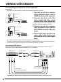
A. Connecting the projector to video equipment
Preparations:
• Check to be sure that the power for the projector and video equipment is turned off.
1 Connect an end of a commercially available video cable to
VIDEO terminal of the projector.
To VIDEO terminal
1
Video cable
DVI
VIDEO
COMPONENT1
Y
Cb/Pb
To video output terminal
Cr/Pr
COMPONENT2
S-VIDEO
RS-232C
2
Video player, or the like.
To S-VIDEO terminal
3
S-video cable
DVI
VIDEO
COMPONENT1
Y
Cb/Pb
To S-video output terminal
Cr/Pr
COMPONENT2
S-VIDEO
RS-232C
4
•
•
•
Video player, or the like.
2 Connect the other end of the
video cable to the video output
terminal of the video equipment.
If S-video output terminal is provided with the video
equipment, make the connection as follows:
3 Connect an end of a commercially available S-video cable to
the S-VIDEO terminal of the projector.
4 Connect the other end of the Svideo cable to the S-video output terminal of the video equipment.
Also, read the instruction manual of the video equipment to be connected.
No speaker for audio output is stored in this projector. To reproduce audio signals, connect audio equipment.
Consult the delivery agent of this projector on the detailed connections, as needed.
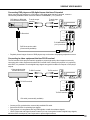
Connecting to DVD players
When connecting this projector to a video equipment that has component video output terminals, such as
DVD players, connect video cables to COMPONENT (1 or 2) terminals.
DVD player or
BS digital tuner
CR(PR) CB(PB)
To audio output
terminals
To audio input
terminals
Y
DVI
VIDEO
COMPONENT1
Y
Cb/Pb
Cr/Pr
COMPONENT2
S-VIDEO
Video cables
(Commercially available)
•
18
RS-232C
To COMPONENT
(1 or 2) terminals
Playback picture images of some of DVD players may not be able to be properly projected on screen.
VIEWING VIDEO IMAGES
Connecting DVD players or BS digital tuners that have D-terminal
When connecting this projector to a DVD player or BS digital tuner that has D-terminal, connect a
commercially available D-RCA conversion cable to COMPONENT (1 or 2) terminal.
DVD player or BS digital
tuner that has D-terminal
To audio output
terminal
To audio input
terminal
DVI
VIDEO
To D-terminal
COMPONENT1
Y
Cb/Pb
Cr/Pr
COMPONENT2
S-VIDEO
RS-232C
To COMPONENT
(1 or 2) terminals
D-RCA conversion cable
(Commercially available)
•
Playback picture images of some of DVD players may not be able to be properly projected on screen.
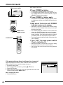
Connecting to video equipment that has DVI-D terminal
The DVI terminal of this projector makes it possible to project high-quality video images on screen by
connecting with a video equipment that has DVI-D terminal. Also, because this projector is in conformity
with HDCP, it is possible to receive digital image signals encrypted from BS tuner outputs or DVD player
outputs.
Video equipment that
has DVI-D terminal
To DVI-D terminal
To DVI terminal
DVI
To DVI-D terminal
VIDEO
COMPONENT1
Y
Cb/Pb
Cr/Pr
COMPONENT2
S-VIDEO
RS-232C
To DVI-D terminal
DVI cable (commercially available)
• Connect to DVI terminal with a commercially available DVI cable.
• Select DVI-DIGITAL for switching input signals.
• This projector is in compliance with only RGB signals, not with chrominance signals.
• HDCP (High-band with Digital Content Protection) is one of encryption formats of digital image signals,
which has been developed by Intel Corporation to protect digital contents.
19
VIEWING VIDEO IMAGES
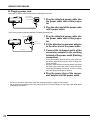
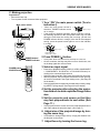
B. Plugging power cord
In the case of power outlets provided with an earthing terminal inlet:
Plug the attached
power cable as it is.
1 Plug the attached power cable into
the power cable inlet of this projector.
Earthing terminal
2
1
Power cable
2 Plug the other end of the power cable
into a power outlet.
In the case of power outlets provided with no earthing terminal inlet:
U-shaped metal
3
4
Power plug
Conversion adaptor
1
2
Power cable
1 Plug the attached power cable into
the power cable inlet of this projector.
2 Fit the attached conversion adaptor
to the other end of the power cable.
3 Connect the U-shaped metal of the
conversion adaptor to the earthing
terminal of the power outlet (Earthing
connection).
•
•
If there is no earthing terminal with the power outlet, ask
the delivery agent of this projector for the earthing work
(To be charged).
Be sure to make earthing connection before connecting
the power plug to the power outlet. Further, when disconnecting the earthing connection, be sure to unplug
the power plug from the power outlet at
4 Plug the power plug of the conversion adaptor into the power outlet.
•
•
20
Be sure to use an AC-100V power outlet with earthing terminal for supply to this projector.
Never connect the earthing metal of the power plug of the conversion adaptor to any of gas pipes, water pipes
and lightning conductors.
VIEWING VIDEO IMAGES
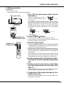
C. Making projection
Preparations:
• Remove the lens cap.
• Turn on power for the connected video equipment.
Main power switch
1 Turn “ON” the main power switch (Turn to
indication I).
•
When the main power switch is
turned on, POWER indicator comes
Lighting in orange
on in orange.
If the projector finished operation without sufficient cooling,
the following operation of the main power button may not work
during the time when the cooling fan is turning. (At this time
POWER indicator blinks in orange.) After the fan has stopped
turning, press the power button again to turn on the indicator
in orange.
MENU/EXIT
ENTER
POWER
LAMP
TEMP
•
Focus ring
Zoom ring
TELE
WIDE
MENU/EXIT
ENTER
Blinking in green
POWER
MENU/EXIT
ENTER
Lighting in green
POWER
LAMP
TEMP
LAMP
TEMP
Power can not be
turned “ON” or “OFF”.
MENU/EXIT
ENTER
POWER
LAMP
TEMP
POWER button
SOURCE button
POWER button /
POWER indicator
SOURCE
C1
C2
DVI
D
COMP1
COMP2
DVI-D
S
V
DVI
A
S-VIDEO
VIDEO
DVI-A
4:3
16:9
ZOOM
DYN
REAL
DYNAMIC
ASPECT
2
•
•
3
1
ENTER
MENU
EXIT
BRI
CONTRAST BRIGHT
COLOR
TEMP
•
ZM
4:3
16:9
REAL
TEM
•
•
It may take about one minute for the lamp to come on.
On rare occasions, the lamp may fail to come on. At this time, turn
on the lamp again after a few minutes.
3 Select an input signal.
POWER ON/OFF
CNT
2 Press POWER ( ) button.
GAM
COL
TIN
COLOR
TINT
SH
•
GAMMA SHARPNESS
LIGHT
LIGHT
Press one of SOURCE buttons (VIDEO, S-VIDEO, COMPONENT
1, COMPONENT 2, DVI-DIGITAL, or DVI-ANALOG button) according to the connected input terminal.
Select the input signal after video image is projected on the screen.
With this projector, the input signal is selected from the input signal sources contained in the signal setting menu. (See Page 26
for the details.)
Some projected picture images may be made easy to see by changing ASPECT (image angle). (See Page 20 for the details.)
4 Set the projector after adjusting the projection distance to obtain specified image frame
size.
5 Set the projector and screen so that they
may face perpendicular to each other. (See
Page 11.)
•
If the projector and the screen can not be made perpendicular to
each other, adjust the projection angle. (See Page 11.)
6. Adjust size of the projected image by turning the zoom ring.
•
It is possible to change image size by varying the distance from
the projector to the screen.
7. Adjust focus by turning the focus ring.
21
VIEWING VIDEO IMAGES
Main power switch
When stopping projection:
8 Press POWER ( ) button.
•
•
A confirmation message appears on the screen.
To cancel this state, wait for a while, or press EXIT button or MENU button of the remote controller, or press
MENU/EXIT button of the projector.
9 Press POWER ( ) button again.
•
TELE
10 Wait about 2 minutes until POWER
indicator comes on in orange.
WIDE
•
MENU/EXIT
ENTER
POWER
LAMP
TEMP
The light-source lamp comes off and the projector comes
to standby state. At this time POWER indicator blinks in
orange.
POWER button/
POWER indicator
•
•
•
POWER ON/OFF
POWER button
SOURCE
C1
C2
DVI
D
COMP1
COMP2
DVI-D
S
V
DVI
A
S-VIDEO
VIDEO
DVI-A
16:9
4:3
ZM
4:3
16:9
ZOOM
DYN
REAL
REAL
DYNAMIC
ASPECT
2
3
1
11 Turn “OFF” the main power switch
(Turn to indication O).
•
ENTER
MENU
CNT
EXIT
BRI
CONTRAST BRIGHT
TEM
COLOR
TEMP
GAM
COL
COLOR
TIN
TINT
Wait about 2 minutes in standby state, because during
this time the intake/exhaust fan is turning to cool down
the light-source lamp.
The intake/exhaust fan continues to turn for about one
minute after POWER indicator has come on in orange.
Do not turn off the main power switch while POWER indicator is blinking. If the main power switch is turned off
immediately after use, the projector may fall in failure.
The fan generates a loud sound while cooling down, but
it is not a failure.
•
When the projector is not used for a long time, unplug
the power plug from the power outlet for safety.
Set the lens cap to prevent dust from being gathered
from outside.
SH
GAMMA SHARPNESS
LIGHT
LIGHT
If the projected image frame is deformed to a trapezoid:
Adjust the trapezoidal correction value contained in the setting menu.
(Refer to Page 25 for the method of setting the menu.)
1. Reveal the setting menu.
2. Select “Trapezoidal correction” by pressing {, } buttons.
3. Press ENTER button.
4. While viewing the image frame, align the upper and lower sides of the
image frame by pressing $, % buttons.
When canceling the menu:
5. Press MENU button.
22
INSTALLATION...
KEYSTONE
KEYSTONE
0
VIEWING VIDEO IMAGES
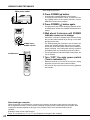
On setting ASPECT (Image angle)
This projector can change ASPECT ratio (The ratio between width and length of image frame) according
to input video signals.
( ): name of remote controller button
16 : 9
Original video
image
4:3
Projects video Projects video
images on full images at a
screen (16: 9). ratio of 4: 3.
ZOOM
DYNAMIC
REAL
Projects video
images of
cinemascope
and vista size
together with the
caption.
Projects 4-to-3
signals by
expanding them
to 16-to-9 images
on full screen
(Nonlinear).
Projects video
images of
input signals
as they are.
Picture images
with a ratio of 4: 3
Projected images
expand in
horizontal direction.
(480i, 576i, 480p,
576p, and PC)
PC inputs not less
than SVGA are
projected on full
screen (16: 9).
*or
Cinemascope
and vista signals
with a ratio of 4: 3
Squeezed 4-to3 images
(480i, 576i,
480p, 576p)
16-to-9 images
(1080i)
16-to-9 images
(720p)
Horizontal and
vertical size of the
projected images are
reduced to a half.
Projected images
are compressed to
the full screen size.
Bold frames are recommended modes.
* In zoom mode, it is possible to switch between display sizes (cinemascope/vista) with ZOOM button.
In cinemascope mode, it is possible to shift the display position with {, } buttons.
How to change the settings:
With the remote controller:
1. Press an ASPECT button (16: 9, 4 : 3, ZOOM, or DYNAMIC).
With the operation panel of the projector.
(Refer to Page 25 for the method of setting the menu.)
1. Reveal the signal setting menu.
2. Select “Image angle” by pressing {, } buttons.
3. Press ENTER button.
4. Select a desired image angle by pressing {, } buttons.
5. Press ENTER button.
When canceling the menu:
6. Press MENU button.
POWER ON/OFF
SOURCE
C1
C2
DVI
D
COMP1
COMP2
DVI-D
S
V
DVI
A
S-VIDEO
VIDEO
DVI-A
16:9
4:3
ZM
16:9
4:3
ZOOM
ASPECT button
DYN
REAL
REAL
DYNAMIC
ASPECT
2
3
1
DISPLAY...
ASPECT
16:9
4:3
ZOOM
DYNAMIC
REAL
23
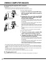
VIWING COMPUTER IMAGES
A. Connecting this projector with a computer
Preparations:
• Make sure that the power for the projector and computer are turned off.
• With a desk-top type computer, disconnect RGB cables connected to the monitor.
In the case of analog connections:
To DVI terminal
1
2
To monitor port
DVI
Y
Cb/Pb
Mini D-SUB 15pin-DVI
conversion cable
Cr/Pr
RS-232C
1 Connect the attached mini D-SUB 15pinDVI conversion cable to DVI terminal of
the projector.
2 Connect the other end of the mini D-SUB
15pin-DVI conversion cable to the monitor port of the computer.
•
•
To DVI terminal
•
1
2
To DVI terminal
DVI
Cb/Pb
Cr/Pr
DVI cable
•
•
A conversion connector, analog RGB output adaptor, and/or
the like may be needed depending on the type of computer to
be connected.
If a long cable other than the attached cable is used, the quality of projected images may be degraded.
When viewing picture images from a computer with analog
connection, press DVI-ANALOG button of the remote controller.
This projector does not comply with 3-line-signals (SYNC-ONGREEN).
This projector does not comply with chrominance signals.
RS-232C
In the case of digital connections:
1. Connect a commercially available DVI
cable to DVI terminal of this projector.
2. Connect the other end of the DVI cable
to DVI terminal of the computer.
•
•
•
•
•
•
•
A conversion connector, analog RGB output adaptor, and/or
the like may be needed depending on the type of computer to
be connected.
If a long cable other than the attached cable is used, the quality of projected images may be degraded.
When viewing picture images from a computer with digital connection, press DVI-DIGITAL button of the remote controller.
Also, read the instruction manual of the other equipment to be connected.
If VGA60 signal outputs at the startup of the computer, the projected image may not be displayed properlyÑüfor
example, the position of the displayed image may be shifted. However, this is not a failure (Non-compliant
signal).
No speaker for audio outputs is stored in this projector. To reproduce audio signals, use the speakers of the
personal computer, or connect necessary audio equipment.
Consult the delivery agent of this projector on the detailed connections, as needed.
B. Plugging power cord
Plug the power cord in the same way as described in “Connecting to video equipment”. See Page 17.
24
VIEWING COMPUTER IMAGES
C. Making projection
Preparations:
• Remove the lens cap.
• Turn on power for the connected video equipment.
Main power switch
1 Turn “ON” the main power switch (Turn to
indication I).
•
When the main power switch is
Lighting in orange
turned on, POWER indicator comes
on in orange.
If the projector finished operation without sufficient cooling,
the following operation of the main power button may not work
during the time when the cooling fan is turning. (At this time
POWER indicator blinks in orange.) After the fan has stopped
turning, press the power button again to turn on the indicator
in orange.
MENU/EXIT
ENTER
POWER
LAMP
TEMP
•
Focus ring
Zoom ring
TELE
WIDE
MENU/EXIT
ENTER
Blinking in green
POWER
MENU/EXIT
ENTER
Lighting in green
POWER
LAMP
TEMP
LAMP
TEMP
Power can not be
turned “ON” or “OFF”.
MENU/EXIT
ENTER
POWER
LAMP
TEMP
POWER button
SOURCE button
2 Press POWER ( ) button.
POWER button /
POWER indicator • It may take about one minute for the lamp to come on.
• On rare occasions, the lamp may fail to come on. At this time, turn
on the lamp again after a few minutes.
3 Select an input signal.
POWER ON/OFF
SOURCE
C1
C2
DVI
D
COMP1
COMP2
DVI-D
S
V
DVI
A
S-VIDEO
VIDEO
DVI-A
4:3
16:9
ZM
4:3
16:9
ZOOM
DYN
REAL
REAL
DYNAMIC
ASPECT
2
•
•
3
1
ENTER
MENU
CNT
EXIT
BRI
CONTRAST BRIGHT
TEM
COLOR
TEMP
•
GAM
COL
TIN
COLOR
TINT
SH
•
GAMMA SHARPNESS
LIGHT
LIGHT
Press one of SOURCE buttons (VIDEO, S-VIDEO, COMPONENT
1, COMPONENT 2, DVI-DIGITAL, or DVI-ANALOG button) according to the connected input terminal.
Select the input signal after video image is projected on the screen.
With this projector, the input signal is selected from the input signal sources contained in the signal setting menu. (See Page 26
for the details.)
Picture images of some input signals may not be projected on the
proper position of the screen. On this occasion, execute “AUTO”
in the signal setting menu of the setting menu. (See Page 30.)
4 Set the projector after adjusting the projection distance to obtain specified image frame
size.
5 Set the projector and screen so that they
may face perpendicular to each other. (See
Page 11.)
•
If the projector and the screen can not be made perpendicular to
each other, adjust the projection angle. (See Page 11.)
6. Adjust size of the projected image by turning the zoom ring.
•
It is possible to change image size by varying the distance from
the projector to the screen.
25
VIEWING COMPUTER IMAGES
Main power switch
When stopping projection:
8 Press POWER ( ) button.
•
•
A confirmation message appears on the screen.
To cancel this state, wait for a while, or press EXIT button or MENU button of the remote controller, or press
MENU/EXIT button of the projector.
9 Press POWER ( ) button again.
•
TELE
10 Wait about 2 minutes until POWER
indicator comes on in orange.
WIDE
•
MENU/EXIT
ENTER
POWER
LAMP
TEMP
The light-source lamp comes off and the projector comes
to standby state. At this time POWER indicator blinks in
orange.
POWER button/
POWER indicator
•
•
•
POWER ON/OFF
POWER button
SOURCE
C1
C2
DVI
D
COMP1
COMP2
DVI-D
S
V
DVI
A
S-VIDEO
VIDEO
DVI-A
16:9
4:3
ZM
4:3
16:9
ZOOM
DYN
REAL
REAL
DYNAMIC
ASPECT
2
3
1
11 Turn “OFF” the main power switch
(Turn to indication O).
•
ENTER
MENU
CNT
EXIT
BRI
CONTRAST BRIGHT
TEM
COLOR
TEMP
GAM
COL
COLOR
TIN
TINT
Wait about 2 minutes in standby state, because during
this time the intake/exhaust fan is turning to cool down
the light-source lamp.
The intake/exhaust fan continues to turn for about one
minute after POWER indicator has come on in orange.
Do not turn off the main power switch while POWER indicator is blinking. If the main power switch is turned off
immediately after use, the projector may fall in failure.
The fan generates a loud sound while cooling down, but
it is not a failure.
•
When the projector is not used for a long time, unplug
the power plug from the power outlet for safety.
Set the lens cap to prevent dust from being gathered
from outside.
SH
GAMMA SHARPNESS
LIGHT
LIGHT
Note-book type computer
When the projector is connected to a note-book type computer, the picture images from the computer may
not be projected on screen. On this occasion, setup the computer so that it may output picture signals. How
to setup the computer depends on the type of the computer. Refer to the instruction manual of the
computer.
Example of setup for the external output:
Press “Fn” key and any of “F1” to “F12” key (Depends on the type of the computer).
26
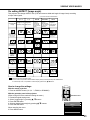
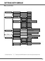
SETTING WITH MENUS
Menu construction
PICTURE...
PRO-PICTURE...
CONTRAST
– 32 ~ +31
BRIGHTNESS
– 30 ~ +30
COLOR
– 30 ~ +30
TINT
– 15 ~ +15
SHARPNESS
– 10 ~ +10
ICC CONTROL
ICC RED
– 15 ~ +15
ICC GREEN
– 15 ~ +15
ICC BLUE
– 15 ~ +15
ICC YELLOW
SET USER COLOR TEMP
LOAD FROM
1 - 512
G GAIN
1 - 512
B GAIN
1 - 512
R BIAS
0 - 90
G BIAS
0 - 90
SAVE TO
OPTION...
9300 / 6500 / 5700 / USER1 / USER2
R GAIN
B BIAS
DISPLAY...
– 15 ~ +15
9300 / 6500 / 5700 / USER1 / USER2
COLOR TEMP
0 - 90
USER1 / USER2
GAMMA
CINEMA1/CINEMA2/VIDEO1/VIDEO2/STANDARD
SOURCE...
VIDEO/S-VIDEO/COMPONENT1/COMPONENT2/
DVI-DIGITAL/DVI-ANALOG
ASPECT...
16:9 / 4:3 / ZOOM / DYNAMIC / REAL
SAVE...
MEMORY1 / MEMORY2 / MEMORY3
YES / NO
RESET ALL
0 / 10 / 20 / 30 / 40 / 50 / 60 / 70 / 80 / 90 MINUTES
AUTO OFF
LAMP HOUR
INSTALLATION...
/ ENGLISH /
LANGUAGE...
RGB & COMPONENT...
AUTO
YES
FREQUENCY
– 15 ~ +15
PHASE
0 ~ 31
H. POS
– 30 ~ +30
V. POS
MIRROR..
KEYSTONE...
/
/
– 30 ~ +30
FLOOR FRONT / CEILING FRONT / FLOOR REAR / CEILING REAR
– 12 ~ +12
PATTERN
•
The items with mark “
” or “...“ requires to press ENTER button to confirm its entry after selecting the item.
27
SETTING WITH MENUS
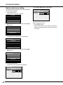
How to make menu setting:
The following figures describe how to set trapezoidal
correction as an example:
1 Press MENU button.
Main menu (the first level) appears.
6 Press $ , % buttons for the setting.
INSTALLATION...
KEYSTONE
KEYSTONE
+4
PICTURE...
PRO-PICTURE...
DISPLAY...
OPTION...
INSTALLATION...
2 Select the menu to be revealed by pressing { ,
} buttons.
PICTURE...
PRO-PICTURE...
DISPLAY...
OPTION...
INSTALLATION...
3 Press ENTER button.
The desired menu (the second level) appears.
INSTALLATION...
LANGUAGE
RGB & COMPONENT
MIRROR
KEYSTONE
PATTERN
4 Select the menu to be revealed by pressing { ,
} buttons.
INTTALLATION...
LANGUAGE
RGB & COMPONENT
MIRROR
KEYSTONE
PATTERN
5 Press ENTER button.
The desired menu (the third level) appears.
INSTALLATION...
KEYSTONE
KEYSTONE
28
0
When canceling the menu
7 Press MENU button.
• When EXIT button of the remote controller is
pressed, the display returns to the menu of the previous level.
SETTING WITH MENUS
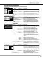
Items that can be set with menus
In this projector, the following items can be set by revealing setup menus.
PICTURE MENU
PICTURE...
0
0
0
0
0
CONTRAST
BRIGHTNESS
COLOR
TINT
SHARPNESS
ITEM
SETTING
FUNCTION
CONTRAST ------- -32 – +31 ---------- Adjusts contrast of projected images. (See Page 28.)
BRIGHTNESS ---- -30 – +30 ---------- Adjusts brightness of projected images. (See Page 28.)
COLOR ------------- -30 – +30 ---------- Adjusts color thickness of projected images. (See Page
28.)
TINT --------------- -15 – +15 ---------- Adjusts tint of projected images. (See Page 28.)
SHARPNESS ----- -10 – +10 ---------- Adjusts sharpness of projected images. (See Page 28.)
PROFESSIONAL PICTURE MENU
PROFESSIONAL-PICTURE...
ICC CONTROL
ENTER
COLOR TEMP
ENTER
SET USER COLOR TEMP
ENTER
GAMMA
ENTER
ITEM
SETTING
FUNCTION
ICC CONTROL ---------------------------- Emphasizes or de-emphasizes independently each of
four colors, RED, GREEN, BLUE and YELLOW.
COLOR TEMP ----------------------------- Selects one of preset color temperatures.
SET USER COLOR TEMP ------------- Selects one of color temperatures that are set in
“Color temperature user adjustment”. (See Page 29.)
GAMMA ------------------------------------- Adjusts favorable color temperatures and stores them.
(See Page 29.)
DISPLAY MENU
ITEM --------------- SETTING ---------- FUNCTION
SOURCE ------------ VIDEO ------------ Select when viewing picture images from a video
equipment connected to VIDEO terminal.
S-VIDEO ---------- Select when viewing picture images from a video
equipment connected to S-VIDEO terminal.
COMPONENT1 ----- Select when viewing picture images from a video
equipment connected to COMPONENT1 terminal.
COMPONENT2 ----- Select when viewing picture images from a video
equipment connected to COMPONENT2 terminal.
DVI-DIGITAL ------- Select when viewing picture images from a digital
equipment connected to DVI terminal.
DVI-ANALOG ------ Select when viewing picture images from an analog
equipment connected to DVI terminal.
ASPECT ------------------------------------- 16:9
Sets picture images to be projected to an aspect ratio
of 16: 9.
4:3 -------------- Sets picture images to be projected to an aspect ratio
of 4: 3.
ZOOM ------------ Projects expanded picture images.
DINAMIC ---------- Projects picture images expanded to full screen.
REAL ------------- Projects picture images keeping the input signals as
they are.
DISPLAY...
SOURCE...
ASPECT...
SAVE...
SAVE ---------- MEMORY1、2、3 ---- Stores the settings made in the PICTURER menu and
the PROFESSIONAL PICTURE menu into MEMORY.
(See Page 27.)
OPTION MENU
OPTION...
RESET ALL
AUTO OFF
LAMP HOUR
ITEM
SETTING
FUNCTION
RESET ALL --------------------------------- Pressing ENTER button reveals a confirmation box.
Select “Yes” and press ENTER button. Then, the
0 MINUTES
settings that were made in the picture quality setting
+11 HOURS
menu and the professional-use picture quality setting
menu are changed to the factory-default settings.
AUTO OFF -------------------------------- 0 ---------------- Auto power off does not function.
10∼90MINUTES ---------- Without picture image signal input, power is
automatically turned off at the preset time.
LAMP HOUR -------------------------------- Indicates used-hours of the lamp. It is not possible to
change the indicated used-hours.
ENTER
29
SETTING WITH MENUS
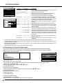
INSTALLATION MENU
ITEM
SETTING
FUNCTION
LANGUAGE
---------5言語
-----------Selects a language used for displays on the screen, such as
LANGUAGE
menus. Adjusts computer video images.
RGB & COMPONENT
RGB
&
COMPONENT
---------------Adjusts computer video images.
MIRROR
AUTO
*
--------------------------------------Selecting Auto and pressing ENTER button automatically
KEYSTONE
adjust position and size of the projected images in
PATTERN
accordance with the image signals from the computer.
FREQUENCY *−15∼+15 -------- If any wide streak pattern appears on the projected images, it
DIASPLAY MENU
can be adjusted with this setting while viewing the images.
INSTALLATION...
PHASE * ------------ 0 ∼ 31 ----------- If any flicker or blur appears on the projected images, it can be
adjusted with this setting while viewing the images.
RGB & COMPONENT
H.POS * --------- −30 ∼ +30 ------- Moves display position of projected images in horizontal
AUTO
YES?
direction.
FREQUENTCY
0
V.
POS
*
--------−30
∼
+30
-------Moves display position of projected images in vertical direction.
PHASE
15
MIRROR ------ FLOOR FRONT ----- Select this setting with the projector set on the floor when
H. POS
0
viewing the projected images from the front side.Normally,
V. POS
0
select this setting.
---------- CEILING FRONT ---- Select this setting with the projector suspended from the
ceiling when viewing the projected images from the front side.
------------ FLOOR REAR ------ Select this setting with the projector set on the floor when
viewing the projected images from the rear side of the screen.
----------- CEILING REAR ----- Select this setting with the projector suspended from the
ceiling when viewing the projected images from the rear side
of the screen.
KEYSTONE --- −12∼+12 -------- Select this setting when correcting trapezoidal distortion.
Normally, select “0”.
PATTERN ----------------------------------- Pressing ENTER button reveals the test pattern for focus
adjustment.
• The items with * mark function only for 1080i, 720p, 525p, and 625p input signals and input signals from DVI terminal.
• The varying range of the vertical position depends on the type of the input signal. With some values the vertical position may not
change, but this is not a failure.
• With the inputs from DVI-DIGITAL terminal, no change appear on the projected images with adjustment of the dividing ratio and
fine, but this is not a failure.
• Without input signals, only some of the above items can be changed.
INSTALLATION...
On the memory for projected image quality
This projector allows each item in the picture quality setting menu and the professional-use picture quality
setting menu (except for color temperature use-adjustment) to be adjusted to up to three kinds of favorable
picture quality for each input signal.
Input that allows the setting
VIDEO
S-VIDEO
COMPONENT 1, 2
DVI-ANALOG/DIGITAL
Number of settings
3
3
3
3
INSTALLATION...
SAVE
MEMORY 1
MEMORY 2
To store the settings:
MEMORY 3
(Refer to Page 25 for how to set menus.)
1. Set an item in the picture quality setting menu and the professional-use picture quality setting menu.
2. Reveal the signal setting menu.
3. Select “Store the setting “ by pressing {, } buttons.
4. Press ENTER button.
The setting storage menu appears.
5. Select the memory where the setting is to be stored by pressing {, } buttons.
6. Press ENTER button.
The setting is stored in the memory.
To cancel the menus:
7. Press MENU button.
To apply the set picture quality:
1. Press MEMORY1, 2, or 3 button.
The picture quality of the projected image comes to the set quality.
30
SETTING WITH MENUS
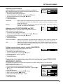
Adjusting projected images
Adjusting brightness of projected images (CONTRAST and BRIGHT)
Items related to brightness of projected images are adjusted with menus.
(Refer to Page 25 for setting menus.)
1 Reveal the picture quality setting menu.
2 Select “CONTRAST” or “BRIGHT” by pressing {, } buttons.
3 Adjust the selected item by pressing $, % buttons.
To cancel the menus:
4 Press MENU button.
PICTURE...
CONTRAST
BRIGHTNESS
0
0
CONTRAST ................... Adjusts vividness of projected picture images.Every time ? button is pressed, the images
are made brighter and more vivid. Every time ? button is pressed, the images are made
darker and less vivid.
BRIGHT .......................... Every time ? button is pressed, the images are made brighter. Every time ? button is
pressed, the images are made darker.
Adjusting color (COLOR THICKNESS and TINT)
Items related to color of projected images are adjusted with menus.
(Refer to Page 25 for setting menus.)
1 Reveal the picture quality setting menu.
2 Select “COLOR THICKNESS” or “TINT” by pressing {, } buttons.
3 Adjust the selected item by pressing $, % buttons.
To cancel the menus:
4 Press MENU button.
COLOR
TINT
0
0
COLOR THICKNESS ..... Adjusts color thickness of projected picture images.Every time ? button is pressed, the
colors are made thicker. Every time ? button is pressed, the colors are made thinner.
TINT ............................... Adjusts tint of projected picture images.Every time ? button is pressed, the skin color of
the projected images is made more reddish. Every time ? button is pressed, the skin
color is made more greenish.
Setting projected images sharper or softer (SHARPNESS)
Sharpness of projected images are adjusted with menus.
(Refer to Page 25 for setting menus.)
1 Reveal the picture quality setting menu.
2 Select “SHARPNESS” by pressing {, } buttons.
3 Adjust sharpness by pressing $ buttons.
To cancel the menus:
4 Press MENU button.
SHARPNESS
0
Emphasizing or de-emphasizing a specified color of projected images (FOUR COLOR
INDEPENDENT CONTROL)
It is possible to emphasize or de-emphasize a specified color (RED, GREEN, BLUE, OR YELLOW) of
projected images with menus.
PROFESSIONAL-PICTURE...
(Refer to Page 25 for setting menus.)
ICC CONTROL
ENTER
1. Reveal the professional-use picture quality setting menu.
2. Select “FOUR COLOR INDEPENDENT CONTROL” by pressing {,
ICC CONTROL
} buttons.
ICC RED
3. Press ENTER button.
4. Select a color to be set by pressing {, }• buttons.
ICC GREEN
5. Set the color by pressing $, % buttons.
ICC BLUE
6. Set the other colors by repeating no. 4 and 5.
ICC YELLOW
To cancel the menus:
7. Press MENU button.
0
0
0
0
31
SETTING WITH MENUS
Adjusting whiteness degree of white color of projected images (Setting COLOR TEMPERATURE)
One of preset color temperatures (degree of white color) is selected with menus.
COLOR TEMPERATURE
(Refer to Page 25 for setting menus.)
1. Reveal the professional-use picture quality setting menu.
9300
2. Select “COLOR TEMPERATURES” by pressing {, } buttons.
6500
3. Press ENTER button.
5700
4. Select a desired color temperature by pressing {, } buttons..
USER1
Åú A favorable color temperature depends on each one’s preference. Generally, 9300 isUSER2
preferably selected
for viewing TV, 6500 is for viewing HDTV, and 5700 is for viewing movies.
Åú When “USER1” or “USER2” is selected, each corresponding color temperature adjusted by user setting
is selected.
To cancel the menus:
5. Press MENU button.
Adjusting degree of white color of projected images (User-adjustment of COLOR TEMPERATURES)
When setting (storing) user’s preferable color temperatures, use “User-adjustment of color temperatures”
in the professional-use picture quality setting menu.
(Refer to Page 25 for setting menus.)
SET USER COLOR TEMP
To store the settings:
1. Reveal the professional-use picture quality setting menu.
LOAD FROM
2. Select “User-adjustment of color temperatures” by pressing {, } buttons. buttons.
5700
6500
9300 USER1 USER2
3. Press ENTER button.
R
GAIN
+256
Åú The menu for user-adjustment of color temperatures appears.
4. Select a basic color temperature by pressing {, } buttons.
G GAIN
+256
Åú Generally, select the most preferable color temperature from preset color temperatures.
B GAIN
+256
5. Press ENTER button.
R BIASchanges according to +45
Åú The selected color temperature is indicated, and the whiteness of projected images
G BIAS
+45
the color temperature.
6. Select the item to be changed by pressing {, } buttons.
B BIAS
+45
7. Set the item by pressing ?, ? buttons.
SAVE TO
USER1 USER2
Åú The projected images also change accordingly.
8. Repeat the settings by repeating no. 6 and 7.
9. Select “User 1” or “User 2” by pressing {, } buttons buttons.
10. Press ENTER button.
Åú The set color temperatures are stored in the memory.
To cancel the menus:
11. Press MENU button.
To bring one of the set color temperatures:
Select “User 1” or “User 2” in “Setting color temperatures” of the professional-use picture quality setting
menu.
On color temperatures
There is various degree of white color. One of the methods of representing degree of white color is color
temperatures. White color of low color temperature is reddish white, and that of high color temperature is
bluish white. In this projector, the color temperatures are set by varying each gain and bias of R (red), G
(green), and B (blue) signal.
To make the color temperature higher:
Set the value of B-gain (or B-bias) larger, and the value of R-gain (or R-bias) smaller.
To make the color temperature lower:
Set the value of R-gain (or R-bias) larger, and the value of B-gain (or B-bias) smaller.
One method of adjusting color temperatures is to make use of person’s skin color. Project a large still
picture of human face on the screen, and adjust the color tone of the face so that it may look favorable
(generally, it may look healthy).
Åú Generally, the gains are used to adjust bright pictures, and the biases are used to adjust dark pictures.
Åú Using the biases is effective in adjusting color of monotone pictures. (It is especially effective for
adjusting dark to intermediate portions.) For example, when the green is relatively strong, decrease the
value of R-bias, or increase the values of both B-bias and R-bias evenly. Also, when the projected images
are bluish, decrease the value of B-bias, and when they are reddish, decrease the value of R-bias. In this
way, favorable picture quality can be obtained.
32
SETTING WITH MENUS
Adjusting picture images sent from computers
This projector automatically sets an appropriate signal processing format according to the image signal
sent from computers. However, depending on the type of the computer, the image signals may not be
projected properly. On this occasion, a countermeasure should be taken as follows:
1. Reveal the setting menu.
2. Select “Setting signals” by pressing Å£, Å• buttons.
3. Press ENTER button.
• The signal setting menu appears.
4. Select “Auto” by pressing Å£, Å• buttons.
5. Press ENTER button.
• Automatic setting is made so that an appropriate setting may be obtained for the input signal.
To cancel the menus:
6. Press MENU button.
If the computer images can not be projected properly with the above operation, adjust the images using
menus as follows:
These settings can be stored in memory of the projector.
How to adjust computer images using menus:
If the following phenomena are observed, adjust as follows:
Projected images are shifted to the left or right:Åc.
Adjust “Horizontal position” in the signal setting menu. Every time ? button is pressed, the projected
image is shifted to the left. Every time ? button is pressed, the projected image is shifted to the right.
Projected images are shifted up or down:Åc.
Adjust “Vertical position” in the signal setting menu. Every time ? button is pressed, the projected image
is shifted downward. Every time ? button is pressed, the projected image is shifted upward.
Projected images blink.
Projected images are blurred:Åc.
Adjust “Fine” in the signal setting menu.
A wide streak pattern appears on the projected images:Åc.
Adjust “Dividing ratio” in the signal setting menu.
Åú Usually, do not change the settings in the signal setting menu.
A simple method of adjusting the position of projected images
Adjusting horizontal position:
1. Align the left edge of the projected image with the left side of the screen by adjusting “Horizontal
position”. Then, align the right edge with the right side of the screen by adjusting “Dividing ratio”.
2. Repeat the above adjustments to align the horizontal position.
Adjusting vertical position:
3. Align the upper edge of the projected image with the upper side of the screen by adjusting “Vertical
position”.
33
REPLACING THE LAMP / CLEANING THE PROJECTOR
The light-source lamp is stored in the projector to project picture images on screen. The light-source lamp is a
consumable part. It may go off or its brightness may decrease during use. In these cases, replace the lamp to new
one in good time. For the replacement, be sure to use the light-source lamp that is sold exclusively for TDP-MT500.
Purchase the lamp from the delivery agent of the projector.
Warning
•
•
•
•
•
Before replacing the light-source lamp, be sure to turn off the main power switch and unplug the power plug.
Replacing the lamp without turning off the main power switch can cause electric shock.
When replacing the light-source lamp, be cautious not to drop the screws fixing the lamp into the inside of the
projector. Do not put any metal pieces or easily flammable things in the projector. If the projector is operated
containing foreign matters, electric shock or fire may be caused. If users can not take out the foreign matters
inside, ask a repair front of Mitsubishi Electric Corporation to take them out.
Securely fix the light-source lamp. If it is not fixed properly, it will not come on and may cause fire.
Never shake the replaced light-source lamp or bring it over face. The lamp may be broken and its broken glass
pieces may be scattered or enter human eyes causing injuries.
Do not replace the light-source lamp immediately after its use, because it is very hot and may cause burn. Turn
off the power button to put off the lamp, and wait about 2 minutes until the cooling fan comes to a complete stop.
Then, turn off the main power switch and unplug the power plug. After more than one hour has passed and the
lamp has been thoroughly cooled down, replace the lamp.
Caution
In this projector, a LAMP indicator blinks after the light-source lamp has been used more than 1000 hours.
When the lamp has been used more than 1300 hours, a warning appears on the screen every time the power
is turned on. After more than 1500 hours of use, the power for the lamp is automatically turned off and the
lamp can not be used any more. Then, replace the lamp to new one as soon as possible.
• Do not remove the light-source lamp except when it is replaced. Otherwise, removing it may cause a failure.
• As the light-source lamp, the high-pressure mercury lamp is used. The high-pressure mercury lamp may burst
with a disruptive sound, if it is shocked or scratched, or if the lamp deteriorates while being used. Also, it may
stop lighting when it comes to its life end. The lapse of time until each lamp bursts or stops lighting, if it occurs,
depends on the characteristics or use condition of each lamp. Therefore, there is a possibility that it may burst
by chance even in a short time after its start of use.
• The possibility of burst of the high-pressure mercury lamp increases if it is used beyond its replacement period.
When the indication of lamp replacement appears, immediately replace the lamp to new one if the lamp is
lighting normally.
• If the high-pressure mercury lamp bursts, the fragments of the glass valve may scatter in and out of the lamp
box, or the gas filled in the valve may come out of the ventilation outlet. The gas filled in the high-pressure
mercury lamp contains mercury vapor. Be extremely cautious not to inhale the gas or bring the gas into eyes or
mouths. If the gas should be inhaled or brought into eyes or mouths, consult a doctor immediately.
• If the high-pressure mercury lamp bursts, fragments of the glass valve are scattered inside of the projector. It is
recommended to ask a service outlet of Mitsubishi Electric Corporation to replace the light-source lamp and
check the interior of the projector. When users make the cleaning and the replacement of the lamp for themselves, be sure to turn the main unit upside down and do it holding the lamp holder. Otherwise, the broken glass
pieces of the lamp may cause injuries.
How to replace the lamp:
(a)
1 Turn the unit upside down.
2 Undo the screw fixing the lamp cover (a)
with a Phillips screwdriver and remove the
lamp cover from the unit.
(b)
3 Undo the three screws fixing the lamp box
with the Phillips screwdriver.
4 Pull up the holder.
Holder
34
REPLACING THE LAMP / CLEANING THE PROJECTOR
5 Holding the holder, pull out the light-source
lamp from the unit.
•
•
Pull out the light-source lamp slowly. If the lamp is burst, the glass
fragments may be scattered if the lamp is pulled out hurriedly.
Do not spray water or the like over the light-source lamp pulled
out, or do not put it where children can access it or near anything
easily flammable. It may cause burn or injury.
6 Holding the holder of a new lamp, insert the
lamp to the bottom fitting the lamp to the
shape of the hole in the unit.
(b)
7 Press the holder into the storage.
•
Make sure that the holder is securely locked.
8 Securely screw down the three fixing screws
(b) with the Phillips screwdriver.
Holder
(a)
9 Insert the lamp cover into the unit, and securely screw down the screw (a) with the
Phillips screwdriver to fix the lamp cover.
•
TELE
10 Turn on the power.
WIDE
▲ button
MENU/EXIT
ENTER
POWER
▼ button
POWER button
LAMP
TEMP
•
•
If the lamp cover is dislocated, the power can not be turned on.
11 Simultaneously press on {, } buttons and
POWER button ( ) on the operation panel of
the unit for more than 3 seconds.
•
If the three buttons are not pressed simultaneously, the lamp-usedhours may not be reset.
If the lamp-used-hours have exceeded 1500 hours and the lamp has been replaced, it is not possible to turn on
the new light-source lamp until the lamp-used-hours are reset.
Do not reset the lamp-used-hours if the lamp is not replaced.
Cleaning dust in the intake vent
If dust is accumulated in the intake vent, the temperature in the projector goes up abnormally, and may
damage the internal parts. Also, the light-source lamp may come off to
protect the internal parts. Clean up
the dust with a vacuum cleaner about once a year.
Exhaust vent
Intake vent
Cleaning the projector
Softly wipe off dirt on the projector with a soft cloth.
• If the dirt is thick, wipe it off with a cloth soaked in a neutral detergent diluted with water, and then finish with a dry
cloth.
• If any pesticide is sprayed over the projector, or if the projector is wiped with benzine or thinner, or if rubber or
vinyl products are brought into contact with the projector for a long period of time, the painting of the projector
may change in quality or removed.
Cleaning the lens
Remove dust or dirt on the lens with a commercially available lens cleaning kit (blower, brush, and the
like).
• Because the surface of the lens is easily scratched, do not rub or hit the surface with anything hard.
35
TROUBLESHOOTING
Before asking for repair of the projector, check the followings: If the problem still continues, stop using
it and be sure to unplug the power plug. Then, contact the delivery agent of the projector.
Picture images are not projected on screen.
Phenomenon
Power can not be turned •
on.
Check/Countermeasure
Check whether the indicators are on or off and how they are lighting.
POWER LAMP TEMP Countermeasure
Off
Off
Off
•
•
•
•
•
Connect the power cable to the projector.
Plug the power plug into a power outlet.
Turn “On” the main power switch.
Fit the rear lamp cover.
If the projector itself is very hot, turn off the power switch, and
after the temperature has come down, turn on the power switch again.
• Replace the light-source lamp. (The lamp is at the end of its life.)
On in orange On in red
On in
Off
Off
On in red
Off
Off
green
→
←
Blinking in
orange
• If the intake and/or exhaust vent is blocked with anything, remove it.
• Prevent the wind from a heater from blowing into the exhaust
vent of the projector, if it is happening.
• Check if the air filter is foul with dust or not.
→Clean the filter, if it is foul.
• Press POWER button after POWER indicator has stopped
blinking in orange.
•
•
Picture images are not
projected on screen.
•
•
•
•
•
•
•
Projected images suddenly disappear.
•
•
36
If the main power was turned “Off” while the fan was still turning, the lamp may not be able
to come on next time for about one minute after the main power switch is turned “On” .
For about one minute after the light-source lamp has been put out, it is not possible to put the lamp on again.
In some cases it takes about one minute to put the lamp on.
On rare occasions, the lamp fails to come on. Then, turn on the lamp again after a few minutes.
If the projector finished operation without sufficient cooling, the cooling fan is turning and the following operation of the main power button may not work after the main power was turned on. (At this
time POWER indicator blinks in orange.) After the fan has stopped turning, press the power button
again to turn on the indicator in orange.
Check if the intake vent is not blocked with anything.
Check to be sure that the lamp cover is closed. (See Page 32 and 33.)
Check if the cable connecting the projector and external equipment is not broken.
When an extension cable is used, replace it with the attached cable for checking. If picture images
are normally projected with the attached cable, employ an RGB signal amplifier together with the
extension cable.
This phenomenon may occur if the intake vent and/or exhaust vent is blocked with anything.
(At this time TEMP (temperature) indicator is lighting in red.)
– After removing those things blocking the intake vent and/or exhaust vent, execute the
followings:
1 Wait until the intake/exhaust fan stops turning. (Wait until TEMP (temperature) indicator comes off.)
2 Turn off the main power switch.
3 Wait about 10 minutes.
4 Turn on the main power switch.
5 Press POWER button.
LAMP indicator lighting in red indicates that the lamp must be replaced. Replace the
light-source lamp to a new one. (See Page 32 and 33.)
TROUBLESHOOTING
Projected images are irregular.
Check/Countermeasure
Phenomenon
Projected images are distorted.
•
Adjust the projector and the screen so that they may become perpendicular to each other. (See Page 11.)
Projected images are •
dark.
•
Adjust BRIGHT and CONTRAST in the picture quality menu. (See Page 28.)
Replace the lamp to a new one. (See Page 32 and 33.)
Projected images are •
blurred.
•
•
•
•
•
Adjust the focus. (See Page 18 and 22.)
Check if the lens cap is not put on.
Clean the lens.
Adjust “FINE” and “DIVIDING RATIO” in the signal setting menu. (See Page 30.)
Adjust BRIGHT and CONTRAST in the picture quality menu. (See Page 28.)
Adjust the projector and the screen so that they may become perpendicular to each other.
(See Page 11.)
This phenomenon is proper to DLP projector and is not a failure. (A very small number of
pixels may be constantly lighting on or off, but this is not a failure. Pixels of more than
99.99% are effective ones.)
White dots are seen in •
projected images.
Black dots are seen in
the projected images.
A rainbow-color brume pattern •
is seen on projected images.
This pattern is a color breaking noise that occurs in DLP system in principle. This is not a
failure.
Fine streak pattern is seen •
on projected images.
This phenomenon occurs due to the interference with the screen surface, and is not a
failure. Try to replace the screen or defocus the lens a little.
Securely plug the cable connecting the external equipment to the bottom.
Keep the projector away from equipment generating interfering radiowaves.
Projected images are •
•
disturbed.
Tint of projected images •
is irregular.
Check if the cable connecting the external equipment is broken.
Others
Phenomenon
Check/Countermeasure
A hot air comes out of
the exhaust vent.
Menu setting is disabled.
• This air comes out after cooling the inside of the projector. It may feel hot, but is not a
failure.
• Affected by noises, the microcomputer in the projector may be malfunctioning.
–>Turn off POWER once, and after 2 minutes turn it on again.
• If POWER can not be turned off, turn off the main power switch and leave the projector as
it is for more than 10 minutes. Then, turn on POWER again.
• On rare occasions, a metallic clank occurs because the color wheel is rotating at a high
speed. But, this is not a failure.
Abnormal sounds occur.
If the following phenomenon occurs after the lamp has been replaced, check the following first:
Phenomenon
Check/Countermeasure
Power can not be
turned on.
•
•
Securely fit the rear lamp cover. (See Page 32 and 33.)
Reset the lamp-used-hours. (See Page 33.)
37
INDICATORS
How to see the internal states from indicators
There are three indicators that inform of the internal states of the projector. The internal states can be
known by how the indicators are lighting. Check the followings, and if there is any problem, stop to use
the projector and be sure to unplug the power plug. Then, contact a repair/customer front of Mitsubishi
Electric Corporation.
MENU/EXIT
ENTER
POWER
POWER indicator
LAMP indicator
LAMP
TEMP
TEMP(temperature) indicator
When the projector is normal:
POWER LAMP TEMP STATE
REMARK
Standby state.
On in orange
Lamp standby state.
Blinking in green
Off
Off
Power can not be turned "OFF".
Power "ON" (usually).
On in green
Lamp is being cleaned.
Blinking in orange
Power can not be turned "ON".
If the projector is not normal:
POWER LAMP TEMP STATE
On in
orange
Off
On in red
On in red
Off
The interior of the projector is very hot.
• The intake vent and/or exhaust vent is blocked
with something.
• The projector is used at a very hot place such as
outlet of heating air.
• The air filter is foul.
Countermeasure
• Remove those things with which the
vent is blocked.
• Relocate the projector.
The protection circuit is working, or
The lamp is not normal.
• Press POWER button after POWER
indicator has ceased blinking.
(When power is turned off normally, this indication appears,
and this is not a failure.)
If this operation is repeated several times and the
light-source lamp still does not come on, replace
the lamp to a new one. Ask the delivery agent of the
projector or a repair/customer front of Mitsubishi
Electric Corporation about purchase of the lamp.
Indicating replacement of the lamp (Used about 1000
hours* in total; Power is "ON".)
Replace the light-source lamp to a new
one. Purchase a light-source lamp from
the delivery agent of the projector.
On in
green
Blinking
in red
On in
orange
Off
On in red
REMARK
Indicating replacement of the lamp (Used about 1000
hours* in total; Power is "OFF".)
• Clean the filter.
Indicating replacement of the lamp (Used about 1500
hours* in total)
Kensington Lock
This projector has a Kensington Security Standard connector for use with a Kensington MicroSaver Security
System. Refer to the information that came with the Kensington System for instructions on how to use it to
secure the projector. Please contact to Kensington Technology Group as shown below.
Kensington Technology Group
2855 Campus Drive
San Mateo, CA 94403, U.S.A.
Phone : (650)572-2700
38
Fax : (650)572-9675
WHEN ASKING INSTALLATION WORK
In the case of suspending the projector from
ceiling and viewing the projected images from
the front side:
When suspending the projector from ceiling, use the
separately sold dedicated metal bracket (see Page 38).
Also, be sure to ask a special worker who received training of the installation work to do the work. Consult
the delivery agent of the projector about the details of
the installation work.
• If the projector is damaged by using any other suspension
bracket than the dedicated one or due to any problem of the
environment in which the suspension metal bracket is installed, Mitsubishi Electric Corporation will not compensate
the damage even if the product is still under warranty.
In the case of installing the projector so that the
picture images are projected onto a semitransparent screen and viewed them from the rear side of
the screen:
When installing the projector, be sure to ask a special
worker who received training of the installation work.
Consult the delivery agent of the projector about the
details of the installation work.
Screen
Projector
• When viewing projected images from the rear side of
the screen, set the projection method in the setting
menu to “Rear”. Refer to Page 27 for the detail.
Projector
Screen
• In the case of the suspension from ceiling, set the projection
method in the setting menu to “Ceiling suspension”. Refer
to Page 27 for the detail.
• Ask the installation worker to provide a power breaker for
the projector. When the projector is not used, be sure to turn
off the main power for the projector with the breaker.
• Where the projector is suspended from ceiling, the brightness of the projected images may be less brighter than where
it is set on floor. However, this is not a failure.
• Do not install the projector where its exhaust vent is directly
exposed to the wind from an air conditioner or the like. Such
installation may cause failures of the projector.
• Do not install the projector near a fire alarm, because hot air
is exhausted form the vent of the projector.
280
181
251
9
44.5
53.5
166
16
167
168
16
33.5
Dimensional drawings (for references)
199
28
28
254
308
108
96
66
235
39
SPECIFICATIONS
Item
Model no.
Projection system
Power
Power dissipation
Resolution
Maximum number of display colors
Light-source lamp
Projection screen
PC image input signal
Video input signal
S-video input
Video input
Analog RGB input
(Mini D-SUB 15P)
Computer digital
input (DVI-D24P)
Control terminal
Maximum outside dimensions
Weight
Power cable
Operating temperatures
Operating humidity
(The specifications and outside appearance of the projector are subject to change without prior notice. Please be notified in advance.)
DLPTM projector
TDP-MT500
DLPTM (Single-Board DMDTM) system
AC 100 V, 50/60 Hz
300 W
1,024 x 576
16,770,000 colors (full-color display)
210-W lamp
Resolution: 640 x 400 (expanded) ~ 1024 x 768 (compressed)
Resolution: 640 x 400 (expanded) ~ 1024 x 768 (compressed)
NTSC /4.43 NTSC / PAL / PAL-N / PAL-M / PAL-60: automatically discriminated
Luminance signal: Vp-p = 1.0 V, 75Ω (negative sync)
Chrominance signals: Vp-p = 0.286 V, 75Ω (burst signal)
Vp-p = 1.0 V, 75Ω (negative sync)
RGB: Vp-p = 0.7 V, 75Ω (negative sync)
YCBCR: Vp-p = 1.0 V (Y) (negative sync), Vp-p = 0.7 V (CB, CR)
HD/CS: TTL-level (negative or positive polarity)
VD: TTL-level (negative or positive polarity)
DVI interface (TMDS single ring)
Serial (DIN 8-pin female terminal): RS-232C specification: one route
30.8 cm (W) x 10.8 cm(H) x 25.1 cm(D): including lens projection and legs
3.4 kg
2.9 m
+5˚C - +35˚C
10% - 90% (except for dew condensation)
Terminals
24
DVI terminal
(DVI-D)
RS-232C terminal
(DIN 8P)
2
1
16
9
8
5
SHELL 8
6
DVI terminal
(DVI-A)
1
17
C5
9
8
C2 C1 16 1
PIN NO.
STATUS
PIN NO.
STATUS
PIN NO.
STATUS
1
DATA 2–
13
–
C1
ANALOG RED
2
DATA 2+
14
+5V Power
C2
ANALOG GREEN
NAME
I/O
3
DATA 2 Shield
15
GND
C3
ANALOG BLUE
1
–
–
4
–
16
Hot Plug Detect
C4
H Sync
2
–
–
5
–
17
DATA 0–
C5
GND
3
RXD
OUT
6
DDC Clock
18
DATA 0+
6
DDC Clock
4
–
–
7
DDC Data
19
DATA 0 Shield
7
DDC Data
5
–
IN/OUT
8
–
20
–
8
Analog Sync
6
–
IN
9
DATA 1–
21
–
14
7
TXD
–
10
DATA 1+
22
Clock Shield
15
GND
8
–
–
11
DATA 1 Shield
23
Clock+
16
Hot Plug Detect
SHELL
GND
–
12
–
24
Clock–
PIN No.
40
3
C4 C3
24
17
+5V Power
SPECIFICATIONS
Type of connectable signals
Signal
representation
480i
576i
480p
576p
720p50
720p59
720p60
1080i25
1080i29
1080i30
VGA
VGA
SVGA
SVGA
SVGA
XGA
XGA
XGA
Resolution
(H x V)
–
–
–
–
–
–
–
–
–
–
640 x 400
640 x 480
800 x 600
800 x 600
800 x 600
1024 x 768
1024 x 768
1024 x 768
Input signal
Horizontal sync
frequency (kHz)
15.73
15.63
31.47
31.25
37.50
44.96
45.00
28.13
33.72
33.75
31.47
43.27
37.88
46.88
53.67
48.36
60.02
68.68
Vertical sync
frequency (Hz)
59.94
50.00
59.94
50.00
50.00
59.94
50.00
25.00
59.94
60.00
70.09
85.01
60.32
75.00
85.06
60.00
75.03
85.00
Screen size
REAL display
(H x V)
720 x 480
720 x 576
720 x 480
720 x 576
1024 x 576
1024 x 576
1024 x 576
960 x 540
960 x 540
960 x 540
640 x 400
640 x 480
800 x 600
800 x 600
800 x 600
1024 x 768
1024 x 768
1024 x 768
• The maximum resolution of this projector is 1024 x 576 dots. It is not possible to obtain more than the maximum resolution for projected images.
• If picture images of a connected computer have a resolution and sync frequency other than those
indicated in the above table, they may be projected by changing the resolution and frequency within
the computer.
• Because XGA60 signal and SVGA60 signal are in conformity with HTPC, they are projected with emphasis on picture quality, and the projected images become a little dark. The other PC input signals
are projected with emphasis on brightness.
• 1080i represents Hi-Vision.
• COMPONENT 1,2 input does not deal with RGB signals.
• DVI-ANALOG input does not deal with chrominance signals.
• If signals out of specification input, they may not be projected properly.
• If VGA60 signal outputs at the startup of the computer, the projected image may not be displayed properly–for
example, the position of the displayed image may be shifted. However, this is not a failure (non-compliant
signal).
41
Printed in Japan