1
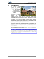
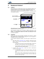
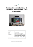
Denham Garden Village
TV, Telephone & Data
User Guide
Version:
1.0
Date:
November 2006
For:
Residents of Denham Garden Village
Contents:
Instructions on how to use, configure
and extend the TV/Satellite &
Telephone/Data systems within the
dwellings at Denham Garden Village
Latest Revision:
www.abledata.co.uk/denham
© Able Data Installations Plc 2006
Denham Garden Village
TV, Telephone & Data User Guide
Contents
1
Introduction ...............................................................................5
2
Support & Assistance ..................................................................7
2.1
General Help & Advice ....................................................................7
2.2
In Depth Help ...............................................................................7
2.3
Download This Guide......................................................................7
2.4
Cables & Parts...............................................................................7
3
Equipment Cabinet......................................................................9
3.1
Cabinet ........................................................................................9
3.2
Patching .......................................................................................9
3.3
Leads......................................................................................... 10
4
The TV System ..........................................................................11
4.1
General Capability........................................................................ 11
4.2
Lounge Socket ............................................................................ 11
4.3
Bedroom & Kitchen Sockets........................................................... 12
4.4
Re-configuring the TV Patch Panel .................................................. 12
4.5
Configuration 1 - Sky+/HD (Default) .............................................. 14
4.6
Configuration 2 – Sky & TV in One Other Room ................................ 15
4.7
Configuration 3 - Sky with Return .................................................. 16
4.8
Configuration 4 – Loft Box............................................................. 18
4.9
Other Configurations .................................................................... 20
5
The Telephone & Data System...................................................21
5.1
Introduction ................................................................................ 21
5.2
Inside the Equipment Cabinet ........................................................ 21
5.3
Connecting Telephone Extensions................................................... 23
5.4
Connecting a Second Line ............................................................. 24
5.5
ADSL Broadband.......................................................................... 24
5.6
Other Applications ....................................................................... 26
Appendix A
Loftbox Re-configuration................................................27
Appendix B
Voice Line Circuit Information ........................................31
Appendix C
Enabling the Sky RF2 Output ..........................................33
Appendix D
Commonly Used Leads & Parts .......................................35
Revision 1.0, November 2006
Page 3
Denham Garden Village
TV, Telephone & Data User Guide
1
Introduction
The
Denham
Garden
dwellings are equipped
with general purpose:
•
TV and Satellite
reception system
•
Telephone/Network
system
Whilst these systems are
configured
to
provide
adequate
TV
and
Telephone services, there may be significant benefits from
understanding how to extend and re-configure the systems to provide
more flexible options.
For example, the TV system as installed (unless the Loft Box extension
has been fitted) will only provide signals to the TV outlets in the Lounge
and Master bedroom. This guide will show you how to re-configure the
system to provide TV signals to any of the TV outlets.
As a further example, the Telephone/Data system as installed will only
provide a telephone line to the Tel/Data outlets in the Lounge. This guide
will show you how to re-configure the system to provide a Telephone line
to any wall outlet.
This guide describes what the systems do and how to set them up to
provide a broader variety of functions.
The guide is aimed at people who have some experience of plugging in
and setting up TV’s or telephones. If this does not apply to you, please
show this guide to the person who is assisting you to set up the TV’s and
Telephones in your dwelling.
Revision 1.0, November 2006
Page 5
Denham Garden Village
TV, Telephone & Data User Guide
2
Support & Assistance
2.1
General Help & Advice
If you require help, please contact the Denham Garden representative
from Anchor Trust, who will do their best to assist. They will be familiar
with the contents of this guide and will be able to advise and assist on
most basic configuration queries.
2.2
In Depth Help
For more in depth help, feel free to contact Able Data, who installed and
maintain the system.
Able Data offer a chargeable consultancy service to Denham Residents
for the setting up and configuring of Audio Visual and Computer
systems.
Able Data Installations
Able House
1 Figtree Hill
Hemel Hempstead
Herts
HP2 5XL
Tel: 01442 219580
Please call during normal working days 8:30 – 17:30.
Alternatively visit the Able Data web site at www.abledata.co.uk/denham
where information about new products and services will be shown.
2.3
Download This Guide
For the latest online version of this manual, visit the Able Data website
at www.abledata.co.uk/denham.
2.4
Cables & Parts
The system is supplied with a base set of cables. However, when you are
connecting up equipment, you will inevitably require additional cables
and parts.
A list of the most common parts may be found in Appendix D. These part
numbers are referenced in this guide as they are mentioned and shown
in blue italics.
Some of the more common parts may be purchased at the Denham
Garden Village shop. Most may also be purchased from high street
electrical outlets.
If a particular part is difficult to source this way, they can be obtained
from Able Data, details as above. Please call for more information and
prices.
Revision 1.0, November 2006
Page 7
Denham Garden Village
TV, Telephone & Data User Guide
3
Equipment Cabinet
3.1
Cabinet
Most changes to the systems will be done in the equipment cabinet. The
equipment cabinet is a small wall mounted cabinet which will normally
be found under the stairs or in the hallway cupboards. All of the
Data/Telephone outlets around the dwelling cables are connected back to
the equipment cabinet.
Most changes can be made by re-patching the patch panels within the
equipment cabinet (see next section).
More advanced changes can be made by adding equipment to the
cabinet. A 4-way power strip is provided inside the cabinet to power such
devices. The Equipment Cabinet will house any standard 10-inch
mounting equipment.
3.2
Patching
Patching is a term used to describe connecting two sockets on a panel
with a patch lead. The patch leads are designed to be easily plugged or
unplugged onto/from the patch panels.
In the Denham Equipment Cabinet, two main types of patch lead are
used:
•
•
Data patch leads (RJ45-Patch-025) (sometime called RJ45 patch
leads). These are used to interconnect sockets on the Data Panel
and Voice Panel.
o
To disconnect one end of a lead (the RJ45 plug), squeeze up
the plastic end at the bottom of the and simply pull out.
o
To re-connect a lead, push into the socket (ensuring the
right way up) until it clicks into place.
TV patch leads (SAT-FF-025). These are used to interconnect
sockets on the TV panel.
o
To disconnect one end of a lead (the F-plug), screw the
metal cap anti-clockwise until it come off. Then pull out the
lead.
o
To re-connect a lead, carefully push the central copper wire
into the socket central hole and then screw the metal cap
clockwise until finger tight.
Revision 1.0, November 2006
Page 9
Denham Garden Village
TV, Telephone & Data User Guide
3.3
Leads
The system is installed with sufficient leads to do basic patching.
However, to connect telephones, televisions, Sky boxes or other
equipment, additional leads will be required. These may be purchased as
described in Section 2.4.
Page 10
Revision Draft 4, July 2006
Denham Garden Village
TV, Telephone & Data User Guide
4
The TV System
4.1
General Capability
Each Dwelling is provided with signals to allow receiving of any of the
following:
•
Standard Analogue Terrestrial TV channels (BBC1, BBC2, ITV1,
CH4, CH5).
•
Freeview (otherwise known as DTT). This provide the same five
channels as above, plus a number of other free to view channels,
such as BBC3, BBC4, BBC News 24, ITV2, ITV3, ITV4 etc.
•
Sky Digital (Sky or Sky+, including Sky HD).
•
FM and DABS Radio.
As part of the national ‘analogue switch off’, it is planned that sometime
in 2012 the Analogue Terrestrial broadcast services in the Denham
Garden Village area will be switched off. From that date on, Freeview will
be the only way of receiving ‘off air’ TV services. If your TV is not
equipped with an integrated digital tuner, you will still be able to receive
standard TV by purchasing a Freeview set top box.
These signals are provided from a centralised reception system in the
Village centre and should always be of the highest quality.
4.2
Lounge Socket
The main TV outlet will be found in the
Lounge. This outlet provides facilities for
receiving standard TV, Satellite and/or radio.
Sat1
Sat2/
Ret
Tel
TV
FM/DAB
Standard TV
A TV plugs into the outlet marked TV (bottom
left above) using a standard TV aerial lead
(TV-Aerial-xxx). This outlet is the equivalent of
the TV aerial socket to be found in many
houses.
Sat1
Sat2/
Ret
Tel
TV
FM/DAB
Either standard analogue TV or FreeView Digital TV may be received.
Hence for example, a FreeView box may be connected to the TV socket
as described in the instructions that come with the FreeView equipment.
Sky Satellite
If you have a Sky subscription and a Sky Digibox, you will be able to
receive Sky TV from the Lounge socket.
1. Plug the Sky Digibox into the Sat1
outlet using a satellite lead (SAT-FFxxx). If you have brought the Digbox
from a home with its own Sky dish, it
will not come with a satellite lead, so
you will need to obtain one.
Sat1
Sat2/
Ret
Tel
TV
FM/DAB
If the Digibox is Sky+ or HD, you will also need to:
•
Connect the Digibox Satellite 2 input to the Sat2/Ret
outlet using a second satellite lead (SAT-FF-xxx).
•
Check that the TV patch panel in the Equipment Cabinet is
properly configured for Sky+/HD – see Section 4.6 below.
Revision 1.0, November 2006
Page 11
Denham Garden Village
TV, Telephone & Data User Guide
2. Plug the telephone connection of the Sky box into the Telephone
outlet on the Lounge Socket. The standard lead that came with
the Sky Digibox may be used. This connection is only required for
the reception of Sky interactive services. However, Sky may also
require you to connect for contractual reasons.
Note: If you find the Telephone connection does not work, it may
be because the Telephone socket has not been properly
configured in the Equipment Cabinet. See Section 5.3.
3. Connect your TV or display into the Sky Digibox using the
standard SCART or others leads supplied with the Digibox.
If you already are a Sky subscriber you will be able setup Sky by
following the instructions above. If however, you wish to start a new
subscription, please contact Able Data as shown in Section 2.2 and they
will be able to provide advice on how to connect.
Radio
IF you have an FM or DABS tuner, you can
receive high quality signals by plugging the
tuner into the FM/DAB outlet.
Sat1
Tel
TV
4.3
Sat2/
Ret
FM/DAB
Bedroom & Kitchen Sockets
Each bedroom & kitchen will have its own TV socket. This
outlet provides facilities for receiving standard TV or
radio.
TV
FM/DAB
Standard TV
A TV plugs into the outlet marked TV using a standard TV
aerial lead (TV-Aerial-xxx). This outlet is the equivalent
of the TV aerial socket to be found in many houses.
TV
FM/DAB
Either standard TV or FreeView Digital TV may be
received. Hence for example, a FreeView box may be
connected to the TV socket as described in the instructions that come
with the FreeView equipment.
Note, that by default, only the first bedroom TV outlet will be connected.
You will need to check that the TV patch panel in the Equipment Cabinet
is properly configured for TV reception in this bedroom. See Section 4.4
below.
Radio
IF you have an FM or DABS tuner, you can receive high
quality signals by plugging the tuner into the FM/DAB
outlet.
4.4
TV
FM/DAB
Re-configuring the TV Patch Panel
In order to configure which TV outlet receives signals, some reconfiguration of the TV patch panel within the cabinet may be required.
The TV patch panel is sited within the Equipment Cabinet.
Panel Layout
Each dwelling receives two independent TV/Sat feeds from the site TV
distribution system. These are presented on the first two outlets of the
TV patch panel.
Page 12
Revision Draft 4, July 2006
Denham Garden Village
TV, Telephone & Data User Guide
The rest of the used panel outlets are connected to the TV outlets within
the dwelling, two to the Lounge Socket and one to each of the Bedroom
Sockets.
1
2
Inputs
Sat1
Sat2
Lounge
Di
Di
Di
Di
1
2
Kitch Bed 1 Bed 2 Bed 3
3
4
Spare
TV Patch Panel
The following sections describe typical configurations.
Revision 1.0, November 2006
Page 13
Denham Garden Village
TV, Telephone & Data User Guide
4.5
Configuration 1 - Sky+/HD (Default)
The table/drawing below shows the standard configuration, which is how
each dwelling is configured when first installed. This provides TV/Sky+ in
the lounge but in no other rooms.
Room
FM/
DABS
TV
Sky
Sky+/HD
Lounge
Kitchen
Bedroom 1
Other
Bedrooms
Lounge
Bedrooms
TV
TV lead from RF1
or SCART/HDMI
Connection
Sky+/HD
Box
No signals supplied to
bedrooms when both feeds
used for Sky+. Loftbox
upgrade will be required for
this option.
Dish 2
Dish 1
SAT-FF-xxx
Tel Lead
supplied with
Sky+ Box
TV Quad Plate
Sat1
Sat2/
Ret
Tel
TV
TV
FM/DAB
FM/DAB
CT100
Cables
TV
FM/DAB
TV
FM/DAB
TV
CT100
Cables
Feeds from
IRS
F Plugs
1
2
Inputs
Sat1
Sat2
Lounge
Di
Di
Di
Di
Kitch Bed 1 Bed 2 Bed 3
1
2
3
4
Spare
TV Patch Panel
SAT-FF-025
TV Patch
Leads
SAT-FF-025
Page 14
Revision Draft 4, July 2006
FM/DAB
Denham Garden Village
TV, Telephone & Data User Guide
4.6
Configuration 2 – Sky & TV in One Other Room
This provides TV/Sky in the lounge (but not Sky+/Sky HD) plus TV in the
first bedroom.
A simple reconfiguration would be to move the Bedroom 1 patch lead
connection to an alternative bedroom or kitchen so that TV can be
viewed in that room.
Room
FM/
DABS
TV
Sky
Sky+/HD
Lounge
Kitchen
Bedroom 1
Other
Bedrooms
Lounge
Bedroom 1
TV
TV
TV-Aerial-xxx
TV-Aerial-xxx
Aerial Fly
Leads (user
supplied)
Radio
Aerial Fly
Leads (user
supplied)
Hi-Fi
TV Quad Plate
Sat2/
Ret
Sat1
Tel
TV
TV
FM/DAB
FM/DAB
CT100
Cables
TV
FM/DAB
TV
FM/DAB
TV
CT100
Cables
Feeds from
IRS
F Plugs
1
2
Sat1
Inputs
Sat2
Lounge
Di
Di
Di
Di
Kitch Bed 1 Bed 2 Bed 3
1
3
2
4
Spare
TV Patch Panel
SAT-FF-025
Revision 1.0, November 2006
TV Patch
Leads
(supplied)
SAT-FF-025
Page 15
FM/DAB
Denham Garden Village
TV, Telephone & Data User Guide
4.7
Configuration 3 - Sky with Return
The Sky Box has the facility for the Sky to be controlled and viewed on a
second TV in another room.
This example configuration shows Sky being repeated in Bedroom 1,
whilst Bedroom 2 receives standard TV. Bedroom 1 will also be able to
receive standard TV channels.
Note:
•
As well as re-patching the TV patch panel as per the schematic
below, an additional Sky Return lead will be required, to connect
the Return 2 of the Digibox to the Sat2/Ret outlet on the Lounge
Socket (Sky-Return-xxx).
•
To watch Sky on the Bedroom 1 TV, the TV will require tuning in
to the Sky channel.
•
In order to control the Sky box from Bedroom 1:
•
o
A tvLINK (Sky-Eye) (often know as Magic eye) infrared
repeater and second Sky remote (Remote-Sky) will be
required. These are available from most TV stores.
o
The Sky Digibox will require setting up through the
Installer Menu. The tvLINK should come with instructions
on how to do this. Alternatively, follow the instructions in
Appendix C.
The Sky Digibox can only output one channel at a time, so the
TV’s in the lounge and bedroom 1 will show the same channel.
Room
TV
FM/
DABS
Sky
Sky+/HD
Lounge
Kitchen
Bedroom 1
View
Lounge Sky
Bedroom 2
Other
Bedrooms
Page 16
Revision Draft 4, July 2006
Denham Garden Village
TV, Telephone & Data User Guide
Revision 1.0, November 2006
Page 17
Denham Garden Village
TV, Telephone & Data User Guide
4.8
Configuration 4 – Loft Box
In order to be able to receive TV signals to all outlets in the dwelling plus
facilitate the viewing of Sky+/Sky HD in the lounge whilst watching Sky
from a bedroom, a loft box will be required.
To see whether you have a loft box already fitted in your dwelling, check
whether there is a black box marked ‘LoftBox’ in the Equipment cabinet.
If not fitted, a Loft Box can be easily added. Please contact Able Data as
described in Section 2.2.
The Loft Box provides:
•
TV signals to all bedroom outlets.
•
The facility for viewing Sky+/Sky HD in the lounge, whilst
watching/controlling the Sky from any of the bedrooms.
Room
TV
FM/
DABS
Sky
Sky+/HD
Lounge
Bedroom 1
View Lounge Sky
(will not be HD)
Bedroom 2
View Lounge Sky
(will not be HD)
Other
Bedrooms
View Lounge Sky
(will not be HD)
The table and schematic below shows how to wire up the Lounge TV/Sky
satellite system, depending on the lounge configuration required:
Lounge
Setup
How to Connect Up
Dist Cab
Setup*
TV Only
Connect TV Aerial socket into TV (TV-Aerialxxx).
Basic TV
Sky
Connect:
Basic TV
•
Sky with
return+
Sky+/Sky
HD with
return+
Sky Sat to Sat1 socket (SAT-FF-xxx).
Connect:
Sky
•
Sky TV to TV socket (TV-Aerial-xxx)
•
Sky Sat to Sat1 socket (SAT-FF-xxx)
•
Sky RF2 to Sat2/Ret socket (Sky-Returnxxx)
You will need to use the diplexer device to
multiplex the Sat2 and Sky return signals
through the Sky2/Ret socket. The diplexor
should be stored in the Distribution Cabinet
when not in use.
Sky
Connect:
Page 18
•
Sky TV to TV socket (TV-Aerial-xxx)
•
Sky Sat1 to Sat1 socket (SAT-FF-xxx)
•
Sky Sat2 to Diplex-SAT (SAT-FF-xxx)
•
Sky RF2 to Diplex-TV (Sky-Return-xxx)
•
Sat2/Ret Outlet to Diplex-IN (Sky-FF-xxx)
Revision Draft 4, July 2006
Denham Garden Village
TV, Telephone & Data User Guide
*
The Distribution Cabinet patch setup may require re-configuring.
See Appendix A on how to do this.
+
Setup return as described in Section 4.7. If Sky+/HD option, use
Sky+ remote on second TV (Remote-Sky+).
Lounge TV Quad Plate
TV Only
Sky
Sat1
Sat2/
Ret
Tel
TV
TV-Aerialxxx
FM/DAB
TV-Aerialxxx
SAT-FF-xxx
Sat2/
Ret
Sat1
SCART
Lead
Tel
TV
FM/DAB
TV In
Sat
RF2
Lounge TV Quad Plate
Cabinet: Basic TV Setup
Cabinet: Sky Setup
Lounge TV Quad Plate
Sat1
Sat2/
Ret
Watch & control Sky
in another room
Tel
TV
FM/DAB
TV-Aerialxxx
TV-Aerialxxx
Sky-Returnxxx
SCART
Lead
TV In
Sat
FM/DAB
Sky Remote
Extender system
(user supplied)
TV
SAT-FFxxx
Sky with
Return
TV
Remote-Sky or
Remote-Sky+
RF2
Sky-Eye
Lounge TV Quad Plate
Sat1
Sky+/Sky HD
with Return
Sat2/
Ret
Tel
TV
TV-Aerialxxx
FM/DAB
SAT-FF-xxx
SCART/
HDMI Lead
Blue leads supplied
with Loft Box Kit
SAT-FF-xxx
SAT-FF-xxx
Sky-Returnxxx
TV In
Sat1
Revision 1.0, November 2006
Sat2
Diplexer
Important: Diplexer &
spare F-leads/Return
lead stored in Patch
Cabinet when not in use
RF2
Page 19
Denham Garden Village
TV, Telephone & Data User Guide
4.9
Other Configurations
It is possible to extend the system to provide a number of different
configurations, such as:
•
TV in all rooms.
•
Sky+ in the lounge plus TV in all rooms.
•
Sky in lounge plus second Sky box in a bedroom.
For more advice or assistance on how to do this, please call Able Data as
shown in Section 2.2.
Important
Because only two feeds come into each dwelling, the upper constraint on
Sky in a dwelling is either:
Page 20
-
One Sky+/HD box
-
Two Sky boxes
Revision Draft 4, July 2006
Denham Garden Village
TV, Telephone & Data User Guide
5
The Telephone & Data System
5.1
Introduction
There are a number of telephone/data outlets distributed around the
dwelling. These are standard RJ45 Cat5e structured cabling outlets,
connected back to the Equipment Cabinet.
The most common use of these outlets is for plugging in telephones.
However, they may also be used for other applications such as computer
networking, TV distribution or any other application that can run over
standard Cat5e structured cabling.
5.2
Inside the Equipment Cabinet
The schematic below shows a typical data panel setup.
Data Panel
There will be one (or sometimes two) outlet panel in the cabinet. Each
socket on this panel is connected to a telephone/data outlet somewhere
in the dwelling. You will be able to work out which by referring to the
labelling. Outlet D1 on the panel is connected to the wall outlet marked
D1 and so on.
Data/Tel & TV Patch Cabinet
Outlet
Panel
Outlet
Panel 2
Voice
Panel
Data/Tel Wall Outlets
D1
D2
D11
D12
1
2
D2
D4
D5
D6
D7
D8
Data/Tel Wall Outlets
D13
D14
Tel Line 1 Exts
3
4
Tel Line 2 Exts
5
RJ45-Patch025
RJ45-Patch025
BT Master
Socket
(Line 1)
D9
6
1
2
3
D10
TV
S1
BT Lines In
L1
L2
S1
RJ45-Patch025
RJ45-Patch025
BT-RJ45
Voice Panel
The bottom panel is the voice panel, onto which the BT extensions are
presented.
•
Line 1. The BT primary line will be connected to the six leftmost
sockets on the panel (labelled 1 to 6), which act as six extensions
to that line. Although it is possible to plug a telephone directly
into any of these six sockets, you would normally patch these
sockets to outlet sockets of your choice, allowing you to plug
telephones into the wall outlets around the dwelling. By default,
Revision 1.0, November 2006
Page 21
Denham Garden Village
TV, Telephone & Data User Guide
the outlets in the lounge, master bedroom and from the lounge
TV plates are pre-patched.
•
Line 2. If a second external telephone line is required (for
example a fax line), this can be connected to the voice panel and
will appear on the next three sockets. As per line 1, these can be
patched through to any outlets of your choice. Note that you will
need to obtain an additional BT-RJ45 lead (BT-RJ45) and use this
to connect the BT second socket to the voice panel (L2 socket).
•
Security System. The Dispersed Alarm security system is
connected inline to the primary telephone line. All connections to
the Dispersed Alarm, including power, are routed via the voice
panel. It is therefore very important that these connections are
not disconnected at any time (the Dispersed Alarm will speak a
warning if a disconnection is made). By convention, the Dispersed
Alarm is always connected to the Telephone/Data outlet in the
hallway. Since the Dispersed Alarm is connected between the BT
incoming line and the extensions, the Dispersed Alarm will be
able to disconnect the main telephone line in the event of an
emergency being raised.
For those extreme technical types, Appendix B details the voice panel
wiring schematic.
Page 22
Revision Draft 4, July 2006
Denham Garden Village
TV, Telephone & Data User Guide
5.3
Connecting Telephone Extensions
If some of the previous section was a little difficult to follow, do not fear
- connecting a telephone is simple:
1. Plug the telephone into a free Telephone/Data outlet. To do this
you will require an RJ45-BT secondary adapter (Tel-Sec).
2. In the Equipment Cabinet check whether the outlet that you have
just plugged into is patched into a Line 1 extension (1 to 6). If
not, use a free RJ45 patch lead (RJ45-Patch-025) to connect your
chosen socket on the data (top) panel to a free socket 1-6 on the
voice (bottom) panel.
Revision 1.0, November 2006
Page 23
Denham Garden Village
TV, Telephone & Data User Guide
5.4
Connecting a Second Line
If a second external line is connected, it should be installed by BT as a
second BT socket within or next to the equipment cabinet. You will then
need to connect from this socket into the L2 socket of the voice panel
using a BT-RJ45 lead (BT-RJ45).
You will then be able to connect telephones and other devices to the
second line by patching outlets to the three extensions on the voice
panel, as per previous section.
5.5
ADSL Broadband
ADSL is the most popular broadband method of connecting to the
Internet.
There are two main schemes for connecting broadband within your
dwelling
ADSL Modem/Router in the Equipment Cabinet
This method provides the most
flexible solution.
Plugs into
computer
ethernet port
When
ordering
the
ADSL
connection, make sure that it
comes with an ADSL modem
which provides at least one
Ethernet connection. Ideally it will
be an ADSL modem/router which
also acts as a network switch and
which typically provides four
network Ethernet ports. Many
such modems also provide a
wireless interface.
Mount the ADSL modem either in
or beside (if it a wireless modem
outside the cabinet is much
better) the Equipment cabinet and
connect it as shown in the
schematic. You will then be able
to connect one or more PC’s to
the internet by patching through
to the modem as shown. Note
that each PC will require an
Ethernet interface.
Page 24
•
Use a wireless connection to
the computer
•
Connect the data and voice
links to the same outlet. It is
possible
to
obtain
combiners/splitters
which
allow a telephone & computer
to share an outlet.
RJ45-Patchxxx
4-pair
Cat5e
Cable
To RJ45
Data Outlets
Data Panel
Voice Panel
1
2
3
4
5
6
7
8
1
2
3
4
5
1
2
L1
TV
L2
ADSL
Sec
Sec
RJ45-Patch025
BT-RJ45
BT Master
Socket
ADSLFilter
RJ45-Patch025
ADSL Modem/
Router
l
Te L
S
AD
The only down side with this
method may be that the network
connection uses up a outlet which
would otherwise serve as a useful
telephone outlet. In this case
consider one of the following:
RJ45 Data
Outlet
Patch Cabinet
Modem kept in cabinet and
connects to one or more computers
through structured cabling.
Modem may also support a Wireless
Interface.
Revision Draft 4, July 2006
ADSL cable
supplied with
modem
Denham Garden Village
TV, Telephone & Data User Guide
ADSL Modem in the room
The other main method of installing ADSL is to put the modem next to
the computer to which it can be directly connected. The modem can then
be of any type (USB or an Ethernet router as described in the previous
section).
To connect the modem, two RJ45-RJ11 (ADSL-RJ45-RJ11) cables will be
required, marked in green in the schematic below.
l
Te L
S
AD
Although it will work, do not be tempted to use a second ADSL filter
connected to the Data outlet, to allow you to split of a telephone next to
the computer. This telephone will effectively be connected before the
Dispersed Alarm security system and therefore potentially compromise
its operation.
Revision 1.0, November 2006
Page 25
Denham Garden Village
TV, Telephone & Data User Guide
5.6
Other Applications
It is possible to extend the system to provide a variety of different
functions.
Examples are:
•
TV distribution system
•
Computer Network
•
Telephone switch
Feel free to Call Able Data to discuss. Alternatively visit the Able Data
web site. See Section 2.2 for details.
Page 26
Revision Draft 4, July 2006
Denham Garden Village
TV, Telephone & Data User Guide
Appendix A
Loftbox Re-configuration
This Appendix applies if your dwelling has been fitted with the Loftbox,
providing a broader range of TV/Satellite connectivity options. See
Section 4.8.
If a Loftbox has not been fitted in your dwelling, but you would be
interested in seeing how much it would cost to upgrade, please contact
Able Data as described in Section 2.2.
The Loftbox will normally be pre-configured in one of two standard
setups, either Basic TV or Sky. Which will depend on the intended use.
•
Basic TV Setup. For when only a TV is being used in the lounge. TV
signals will also be provided to the bedroom outlets. A Sky box (not
Sky+ or Sky HD) may also be connected, but the return output
cannot be used.
•
Sky Setup. For when Sky, Sky+ or Sky HD is being used in the
lounge. It allows the return from Sky (together with other terrestrial
signals) to be fed to the bedrooms. If for any reason the Sky return
is not connected, use the Basic TV Setup, otherwise no TV signals will
be received in the bedrooms. This mode is also applicable, even if
Sky is not being used, when the return from other equipment (such
as VHS recorder, DVD player, FreeView receiver) can be utilised.
The schematic below shows how the two different modes are connected
within the Equipment Cabinet.
Revision 1.0, November 2006
Page 27
Denham Garden Village
TV, Telephone & Data User Guide
IRS
IN1
IRS
IN2
Basic TV Setup
F-plug leads
Use this option when
resident does not
either use Sky or use
an RF return.
Note: In Terrestrial TV
mode, Sky can still be
received in Lounge, but
the Sky return cannot be
connected to allow viwing
in the bedrooms.
Living
Room
Sat2/
Return
Out Out Out
1
2
3
IRS In2 lead left
disconnected
In other rooms either:
- Watch terrestrial TV
- Listen to radio.
SAT-FF-050
SAT-FF-050
1
2
Sat1
Sat2
Di
Lounge
Inputs
Di
Di
Di
1
2
Kitch Bed 1 Bed 2 Bed 3
3
4
Spare
TV Patch Panel
IRS
IN1
IRS
IN2
Sky Setup
F-plug leads
Use this option when
resident uses Sky.
Also appliciable if resident
wishes to feed the RF
output of a DVD/VCR/
FreeView to the bedrooms.
Living
Room
Sat2/
Return
Out Out Out
1
2
3
In other rooms either:
- Watch terrestrial TV
- Watch the Sky program
- Listen to radio.
SAT-FF-050
SAT-FF-050
1
2
Sat1
Sat2
Lounge
Inputs
Di
Di
Di
Di
Kitch Bed 1 Bed 2 Bed 3
1
2
3
4
Spare
TV Patch Panel
To switch between modes:
Page 28
Mode
Change
Steps
Terrestrial
to
Sky/Sky+
1.
Disconnect the black patch lead on Panel Input 2
and re-connect to Panel Lounge Ret.
2.
Connect the unconnected lead (IRS IN2) to Panel
Input 2.
Sky/Sky+
to
Terrestrial
1.
Disconnect the black patch lead on Panel Input 2
and leave floating.
2.
Disconnect the black patch lead on Panel Lounge
Ret and re-connect to Panel Input 2.
Revision Draft 4, July 2006
Denham Garden Village
TV, Telephone & Data User Guide
There are other modes which may be employed, to say configure for Sky
Multi-room, as shown in the schematic below. Note that this
configuration will also require the TV outlet plate in Bedroom 1 to be
swapped out for a Triplex Plate.
Equipment Cabinet
IRS
IN1
IRS
IN2
The system can also be configured for Sky
Multi-room (Sky two-way).
This configuration shows the Multiroom in
Lounge & Bed, return coming from the
Lounge. Any other combination of rooms is
also possible by appropriate change of
patch connections.
SAT-FF-050
Living
Room
Sat2/
Return
Out Out
2
3
SAT-FF-050
SAT-FF-050
1
2
Sat1
Sat2
Di
Lounge
Inputs
Di
Di
Di
Kitch Bed 1 Bed 2 Bed 3
1
2
3
4
Spare
TV Patch Panel
Bed 1
Lounge
TV Triplex
Lounge TV Quad Plate
Sat1
Sat2/
Ret
TV-Aerialxxx
TV
FM/DAB
Tel
TV-Aerialxxx
TV
FM/DAB
SCART
Lead
SAT-FFxxx
SCART
Lead
SAT-FFxxx
SkyReturnxxx
TV In
TV In
Sat
Sat
RF2
Revision 1.0, November 2006
Page 29
Note: Bedroom 1
diplex is
replaced with a
Triplex Satellite
outlet socket
Denham Garden Village
TV, Telephone & Data User Guide
Appendix B
Voice Line Circuit Information
Revision 1.0, November 2006
Page 31
Denham Garden Village
TV, Telephone & Data User Guide
Appendix C
Enabling the Sky RF2 Output
By default, a new Sky Box will output nothing from the RF2 output.
However once enabled, RF2 will both output the Sky channel to another
TV and accept tvLINK remote commands attached to that TV.
To enable RF2:
1. On the Sky remote, select ‘System Setup’.
2. Enter in sequence ‘0’, ‘1’ & ‘Select’. This will take you to the
Installer Setup Menu.
3. Select Option 4 (RF Outlets), taking you to the RF Outlets menu.
4. Set the RF Outlet Power Supply to ON (default is OFF).
5. [Another handy option here is the one to change the RF Channel
Number on which the Sky outputs RF and RF2 outputs are set.
This may be necessary in order to not conflict with broadcast
channels or other equipment such as a VCR or DVD player. A
good default channel for Denham is 60, which conflict with no
broadcast channels]
6. Save New Settings.
Revision 1.0, November 2006
Page 33
Denham Garden Village
TV, Telephone & Data User Guide
Appendix D
Commonly Used Leads & Parts
Part No
Description
Use
Telephone
Tel-Sec
BT-RJ45
Secondary Cat5 Adapter
BT to RJ45 Lead (0.5m)
Plug telephone into wall sockets
Alarm-LL4000
AlarmSayPhone21
Tunstall LL4000 Dispersed Alarm
RJ45 Power & Voice In/Out Lead
SayPhone21 Dispersed Alarm RJ45
Power & Voice In/Out Lead
Connect BT 1st or 2nd line into SOHO
voice panel
Cable to connect the Tunstall LL4000
Dispersed Alarm unit to a wall data outlet
Cable to connect the SayPhone21
Dispersed Alarm unit to a wall data outlet
ADSL
ADSL-RJ45-RJ11
ADSL RJ11 to RJ45 Lead
ADSL-Filter
ADSL Filter approved for use with
Dispersed Alarm System
Connect ADSL USB modem to wall
socket. Two required.
Connect into BT wall socket to separate
ADSL.
Cat5e Data/Voice Patch Leads
Cat5e RJ45-RJ45 Patch Lead
(0.25m)
Cat5e RJ45-RJ45 Patch Lead (1m)
Cat5e RJ45-RJ45 Patch Lead (2m)
Cat5e RJ45-RJ45 Patch Lead (3m)
General patch lead for SOHO cabinet
Satellite Lead (0.25m)
F-plug to F-Plug.
Satellite Lead (0.5m)
F-plug to F-Plug
Satellite Lead (2m)
F-plug to F-Plug
Satellite Lead (3m)
F-plug to F-Plug
Short TV Sat lead for SOHO cabinet –
typically used for patching on panel
TV Lead (2m).
IEC Male to IEC Female.
TV Lead (3m)
IEC Male to IEC Female.
TV lead for connecting TV to wall socket
or Video to TV.
Sky Return to F-Plug (2m).
IEC Female to F-Plug.
Sky Return to F-Plug (3m)
IEC Female to F-Plug.
Connect Return from Sky box to Sat2 wall
socket to watch Sky in bedrooms
Sat-Split-2
2-way splitter with Sat return path
Remote-Sky
Sky Digibox Remote Control
Remote-Sky+
Sky+/HD Remote Control
Sky-Eye
Global TV Link Eye (Black)
Split off signal to bedroom, where both
input feeds are being used by Sky+.
Install in SOHO cab.
Spare remote. Use with TV Link for
remote in 2nd room.
Spare Sky+/HD remote. Use with TV Link
nd
for remote in 2 room.
Allows control of a Sky Box in another
room. May be used with Sky or Sky+/HD.
RJ45-Patch-025
RJ45-Patch-100
RJ45-Patch-200
RJ45-Patch-300
General patch lead for computer into wall
General patch lead for computer into wall
General patch lead for computer into wall
Satellite/RF Leads
SAT-FF-025
SAT-FF-050
SAT-FF-200
SAT-FF-300
Long TV Sat lead for SOHO cabinet –
typically used for Loft Box connections
TV Sat lead for connecting Sky box to wall
socket. Sky+/HD requires two leads.
TV Sat lead for connecting Sky box to wall
socket. Sky+/HD requires two leads.
TV Aerial Leads
TV-Aerial-200
TV-Aerial-300
TV lead for connecting TV to wall socket
or Video to TV.
Sky Return Leads
Sky-Return-200
Sky-Return-300
Connect Return from Sky box to Sat2 wall
socket to watch Sky in bedrooms
TV Parts
Revision 1.0, November 2006
Page 35