1
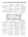
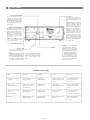
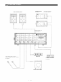
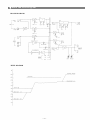
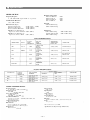
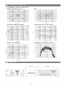
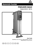
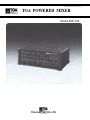
Operating Instruction Manual
TOA POWERED MIXER
Model MX-104
TOA ELECTRIC CO., LTD.
KOBE, JAPAN
Contents
General Description
2
Features
2
Front Panel [Names of components & their usage]
3
Rear Panel [Names of components & their usage]
4
Connection Examples
5
Input Connections
6
Block and Level Diagrams
7
Specifications
8
Characteristics Diagrams
9
Appearance
9
Precautions
1. XLR Type Audio Connector
The connectors are wired as follows.
The pin 1 is ground [shield), the pin 2 cold (low, minus), the pin 3 hot (high, plus).
2. Description of components and functions on the MX-104.
Various descriptions are applied, depending on each manufacturer. In our
Operating and Instruction Manual explanation of components and functions is
made according to our usage for them.
— 1 —
General Description
The TOA MX-104 is a very compact, four channel self-powered mixer. It was
designed to deliver maximum features and performance in a cost-effective portable
PA package.
The MX-104 features four input channels, one program output, and one Foldback
output. The internal amplifier is rated at 100 watts into an 8 ohm load, and 150 watts
into 4 ohms.
Each input channel has an electronically balanced XLR connector, and a highimpedance unbalanced 1/4" phone jack. In addition, each channel features two-band
EQ, a pre-EQ Foldback send, and post-EQ reverb send.
The master control section features a patchable 5-band graphic equalizer, a quality 3spring reverb, a full patch bay with 1/4" phone auxiliary and RCA tape inputs, and
master volume controls for Program, Foldback, and Reverb return to both. The power
amp protection circuitry and autocomp compressor, both with LED's, are also located
in this section.
Features
1. Four input channels
2. 100 watts into 8 ohms, 150 watts into 4 ohms
3. Patchable 5-band graphic EQ
4. Auto Comp compression unit w/LED
5. Built-in spring reverb
6. Power amp protection circuitry w/LED
7. Full patch bay
8. Aux input w/level control, RCA jacks and parallel phone 1/4" jacks.
9. Reverb level to PGM and FB
10. Independent Foldback mix.
Each Channel
1. Input level control
2. Two band EQ
3. Pre-EQ Foldback send
4. Post-EQ Reverb send
5. Low-Z electronically balanced XLR input
6. Hi-Z unbalanced 1/4" input
—2—
Front Panel
High Equalizer Control
(HIGH)
The high EQ control alters the
high frequency response of the
input channel, providing ±13dB
at 10kHz, and ±15dB at 20kHz of
continuously variable active
shelving equalization. The "0"
detented position provides flat
audio response.
Low Equalizer Control
(LOW)
The low EQ control provides
±13dB at 100Hz and ±15dB at
50Hz of continuously variable
active shelving equalization.
The "0" detented position provides flat audio response.
Input Level Control
(LEVEL)
The level control provides continuously variable adjustment
of the channel output to the
program mixing buss, thus
determining the level of that
channel in the main sound
system mix. Since the reverb
signal is "post" this control, an
increase in the level of the
channel's output will also result
in a corresponding increase in
the reverb effect of that channel.
The nominal level of the input
level control is at the "10" position.
High Impedance Connectors
(HIGH Z)
These connectors are unbalanced, standard 1/4" phone jacks
with an input impedance of 27k
ohms, and an input level of
-35dB. When a plug is inserted
into the high - Z input, the corresponding XLR connector is
automatically switched out of the
input circuitry.
Low Impedance Connectors
(LOW Z)
The XLR connectors are low impedance, electronically balanced
inputs with an input impedance
of 1k ohms.
Graphic Equalizer
(EQUALIZATION)
The graphic equalizer is 5 independent active bands ( f i l t e r s ) ,
providing 12dB of boost or cut at
each center frequency. The "0"
detented position provides f l a t
audio response.
Reverb to Foldback
Control (REV TO FB)
This control adjusts the amount
of reverb signal that is returned
to the foldback buss and thus the
level of reverb contained in the
on-stage monitor mix.
Reverb/Control
(REV)
This control determines the
level of signal assigned to the reverb mixing buss. Rotating the
control clockwise increases the
amount of reverb in that channel.
Foldback Master Control (FB)
The FB master control adjusts
the overall combined signal level
of the four independent channel
foldback sends, and thus the
level of the entire on-stage monitor mix.
Foldback Control (FB)
The Foldback control determines the level of signal assigned to the foldback mixing buss,
thus setting the level of that
channel in the on-stage monitor
mix.
Aux Level Control (AUX)
This control sets the overall level
of the Aux input signal.
Power Amp Compression
Indicator
(COMP)
The Comp LED lights when the
internal compressor is activated.
The compressor is provided to
protect speaker systems by compressing the input signal level of
the power amplifier when clipping occurs in the output stage.
Frequent flashing of the LED is
not reason for alarm. However, a
constant or steady light indicates
that the MX-104 is being overdriven and that the internal
power amplifier is possibly
"under powered" for that application. The output level of the MX104 should be decreased until the
LED only flashes intermittently.
Power Indicator LED
(POWER)
The indicator LED lights when
the power switch is "on".
Reverb to Program Contro1
(REV TO PGM)
This control adjusts the amount
of reverb signal that is returned
to the program buss and thus the
level of reverb contained in the
main sound system.
Graphic Equalizer Input Jack (GEQ IN)
The GEQ i n p u t jack allows t h e
graphic equalizer to be used ind e p e n d e n t l y of t h e MX-104 w i t h
other external e q u i p m e n t , or t h e
i n t e r n a l power amplifier and the
graphic equalizer w i t h e x t e r n a l
e q u i p m e n t . When a plug is
inserted, the main mix from
t h e program buss is disconnected
from the graphic equalizer and
the power a m p l i f i e r . The nominal input level is +4dB w i t h an
i n p u t impedance of 50k ohms.
Power Amp Protection
Indicator (PROTECT)
The indicator LED lights if the
power amplifier output is shorted, if the temperature of the unit
rises above acceptable levels, or
if DC is drifted to the speaker
outputs. If the LED should light,
speaker wiring and ambient
temperature of the MX-104
should be checked. If the LED
remains lighted, the unit should
be referred to qualified service
personnel for repair.
Note:
The MX-104 protection circuitry
will (1) detect 'faulty conditions'
within the power amplifier, (2)
give a visual indication, and (3)
automatically shut down until
the f a u l t condition is alleviated.
This special circuitry ensures
maximum reliability and virtually eliminates equipment
damage due to unsafe or fault
conditions. Please refer to fault
p r o t e c t i o n table on page 4 for
f u l l explanation of this important feature.
Graphic Equalizer Output Jack
(GEQ OUT)
This j a c k allows t h e MX-104
and t h e i n t e r n a l g r a p h i c e q u a l izer to be used w i t h an e x t e r n a l
power a m p l i f i e r , or in c o n j u n c t i o n w i t h t h e GEQ in j a c k , to be
used i n d e p e n d e n t l y of all o t h e r
MX-104 c i r c u i t r y . N o m i n a l
o u t p u t level is +4dB w i t h an
i m p e d a n c e of 600 ohms.
Power Amplifier Input Jack
(PWR IN)
The PWR Amp i n p u t jack allows
the i n t e r n a l power amplifier to
be used w i t h e x t e r n a l equipment. When a plug is inserted,
t h e power amp is a u t o m a t i c a l l y
disconnected from the MX-104
m i x e r section. The nominal inp u t level is +4dB w i t h an i n p u t
i m p e d a n c e of 10k ohms.
Program Output Jack
(PGM OUT)
The PGM Out jack is provided
for connection to external equalizers and/or power amps, deriving its signal prior to the internal
GEQ and power amp. Nominal
o u t p u t level is +4dB with an
impedance of 600 ohms.
Program Master Control
(PGM)
The PGM control adjusts the
overall combined signal level of
the four independent channel
level controls, and thus the level
of the main sound system.
Aux Input Jacks
(AUX IN)
The phone jack and RCA pin
jacks are wired in parallel, with
an input level of -20dB. When a
plug is inserted into the phone
jack, the RCA pin jacks are
automatically switched out of
the AUX circuitry.
Foldback Output Jack
(FB OUT)
This jack is for connection to
external power amplifiers and/
or equalizers for the on-stage
monitoring system. Nominal
o u t p u t level is +4dB w i t h an
impedance of 600 ohms. If the
internal power amp and equalizer are to be used for the onstage monitor system, the FB
o u t p u t should be connected to
the GEQ input jack.
—3—
Rear Panel
Power Switch (POWER)
The power switch is a threeposition type with the middle
position being the "off position.
The MX-104 should be operated
in the switch position which
produces the lowest amount of
system hum.
Cord Wrap
The cord wrap is provided for
convenient storage of the power
cord when the MX-104 is not in
use.
Caution - The power cord should
always be completely removed
from the cord wrap prior to
operation of the unit. This will
insure maximum cooling of the
MX-104. For the same reason,
adequate clearance should be
maintained between the rear
panel and any other surface (4-6
inches should do). The vents on
the bottom and top of the MX104 are also provided for convection cooling. These vents should
be kept clear and open. Failure to
do so may cause thermal shutdown of the unit.
Speaker Jacks (SPEAKERS)
The speaker outputs are standard 1/4" phone jacks wired in
parallel. Speaker cables (recommend at least #18 gauge wire)
should be connected between
the MX-104 and the speaker
systems prior to applying power
to the unit.
Caution - The MX-104 should
never be operated into less than
a 4 ohm speaker load.
Earth Terminal (GND)
AC Power Cord
The power cord is the three-wire
type with proper grounding facilities.
Caution - The ground pin should
not be removed under any circumstances. If the MX-104 must
be used without proper grounding facilities, a suitable grounding adapter should be utilized.
Warning - To avoid possible
equipment damage and/or personnel injury, the fuse should
always be replaced with same
type and rating. Using improper
fuses will also void the warranty. The MX-104 should always
be disconnected from AC outlet
prior to changing fuses. If fuse
repeatedly fails, the unit should
be referred to qualified service
personnel for repair.
Operation of the MX-104 with
proper grounding techniques
will result in less system noise
and greatly reduced shock
hazard.
Fault Protection Table
Fault
Protection
Indication
Action
Restoration
Excessive current due to
overloads.
Current limiter activates at
less than 2 ohm.
Compressor
LED illuminates.
Remove excessive loads.
Minimum speaker loads
4 ohm.
Automatic restoration
after normal loads are
obtained.
Short circuits
(less than 0.4-ohm)
Current limiter activates,
input signal is lowered,
unit shuts down,
Amp protection
LED illuminates.
Check speaker
lines/systems for shorts.
Turn off power switch.
Turn on into operational
loads.
Temperature rise of heat
sink
(more than 105°C)
Input signal is lowered.
Unit shuts down.
Amp protection
LED illuminates.
Check for adequate
ventilation.
Automatic restoration
after temperature
lowers (to 75° - 95° C)
DC drift
Input signal is lowered.
Unit shuts down.
Amp protection
LED illuminates.
Refer to qualified service
personnel.
Automatic restoration
after normal bias is
regained.
—4—
Connection Examples
SPEAKER SYSTEM
for foldback
MAIN SPEAKER SYSTEM
(Self powered speakers
TOA model SM-25A)
From Speaker jack
on Rear Panel
KEYBOARD
Low Z input should be connected
with low impedance (50 ohm ~ 600 ohm)
microphones
CASSETTE TAPE DECK
for playback
MUSICAL INSTRUMENT
— 5 —
Input Connections
Generally speaking, there are two rules to follow when connecting equipment outputs
to the inputs of other equipment.
1. Properly match the impedances of the outputs and inputs.
2. Connect low impedance outputs to high impedance inputs.
It goes without saying that not only input and output impedance matching, but also
level matching should be taken into consideration. Each input channel of the MX-104
is provided with an Input Level Control that includes a negative feedback (NF)
circuitry, so the usable signal level range is wide. Input impedances and levels are
shown in the following table.
INPUT SPECIFICATIONS
FOR USE
WITH
NOMINAL
SENSITIVITY*
(PGM OUTPUT
LEVEL +4dB)
CONNECTOR
MICROPHONES
-60dB (0.78mV)
XLR TYPE NC3F
LOWER IMP
LINES
-35dB (13.8m V)
PHONE JACK
AUX
LOWER IMP,
LINES
-20dB (77.5mV)
RCA PIN JACK
PHONE JACK
GEQ
LOWER IMP,
LINES
+4dB (1.23V)
PHONE JACK
PWR/AMP
LOWER IMP,
LINES
+4dB (1.23V)
PHONE JACK
CONNECTION
INPUT
ACTUAL
LOAD
IMPEDANCE
CH1
LOW Z
OPEN
CH4
HIGH Z
*Sensitivity is the level required to produce a program out level of +4dB.
*0dB is referenced to 0.775V RMS.
All XLR Type connectors are electronic balanced. Phone jack is unbalanced.
If the line going from one piece of equipment to another is long (more than 5m), we
recommend that balanced outputs be connected to balanced inputs.
As is described in the beginning of the Operating Instructions Manual, the connectors
of the MX-104 are wired as follows: Pin 1 is ground (shield). Pin 2 is cold (low, minus).
Pin 3 is hot (high, plus).
—6—
Block and Level Diagrams
BLOCK DIAGRAMS
LEVEL DIAGRAM
—7—
Specifications
MIXER SECTION
Maximum Voltage Gain
INPUT to PGM out
INPUT to FB out
INPUT to GEQ out
AUX to PGM out
Frequency Response
+0, -3dB 60Hz~20kHz (input LEVEL at "5" position)
Total Harmonic Distortion
0.05% +4dB* at 1kHz.
64dB
64dB
64dB
24dB
Input EQ
50Hz ±15dB Shelving
20kHz ±15dB Shelving
Hum and Noise (Open)
Equivalent Input Noise
-130dB* (20Hz ~ 20kHz)
Equivalent Input Noise
-133dB* (IHF A)
All level Controls Minimum
-110dB* (IHF A)
PGM Master at MAX and all
input level controls minimum -90dB* (IHF A)
PGM Master at MAX and one
input level control at MAX -70dB* (IHF A)
Equalization
63Hz ±12dB Peaking
250kHz ±12dB Peaking
1kHz ±12dB Peaking
2kHz ±12dB Peaking
8kHz ±12dB Peaking
INPUT SPECIFICATIONS
FOR USE
WITH
NOMINAL
SENSITIVITY*
(PGM OUTPUT
LEVEL +4dB)
CONNECTOR
MICROPHONES
-60dB(0.78mV)
XLR TYPE NC3F
LOWER IMP
LINES
-35dB (13.8m V)
PHONE JACK
AUX
LOWER IMP,
LINES
-20dB (77.5mV)
RCA PIN JACK
PHONE JACK
GEQ
LOWER IMP,
LINES
+4dB (1.23V)
PHONE JACK
PWR/AMP
LOWER IMP,
LINES
+4dB (1.23V)
PHONE JACK
CONNECTION
INPUT
ACTUAL
LOAD
IMPEDANCE
CH1
LOW Z
OPEN
CH4
HIGH Z
OUTPUT SPECIFICATIONS
CONNECTION
ACTUAL
SOURCE
IMPEDANCE
FOR USE WITH
NOMINAL
NOMINAL
OUTPUT LEVEL*
MAX. BEFORE
CLIP
CONNECTOR
PGM
+4dB [1.23V]
+20dB (7.75V)
PHONE JACK
GEQ
+4dB (1.23V)
+20dB (7.75V)
PHONE JACK
FB
+4dB (1.23V)
+20dB (7.75V)
PHONE JACK
POWER AMPLIFIER SECTION
Frequency Response
+0, -1dB 15Hz to 30kHz (150W RMS
Rated Power & Load
150W RMS
HOW RMS
Power Output at Clipping
1% THD, 1kHz
160W RMS
115W RMS
Total Harmonic Distortion
Less t h a n 0.1% (200mW ~ 150W RMS, 20Hz~20kHz, 4
Typically below 0.05%
Compresser Dynamic Range
Greater t h a n 26dB
Hum and Noise
At least 105dB S/N ratio, 20H/~20kHz
At least 109dB S/N r a t i o IHF-A weighted
Damping Factor
Greater t h a n 200
Input Sensitivity
+4dB* (1.23V)
Input Impedance
Output Connector
Phone Jack x 2
Power Requirement
294 W 120V AC 60Hz
Dimensions
494(W) X 184(H) X 304(D)
(19.44 X 7.24 X 11.97) ins.
Weight
10 kg (22 l b s )
*0dB is referenced to 0.775V RMS.
* Specifications are subject to change without notice.
—8—
Characteristics Diagrams
LOW Z HIGH Z IN & INPUT EQ (LEVEL Control)
HIGH Z IN. & INPUT EQ (se t at "5")
GEQ
POWER AMP POWER BAND WIDTH
POWER AM P T.H.D. vs POWER OUTPUT
POWER AM P COMPRESSOR
REVERBERATION FREQUENCY RESPONSE
Appearance
—9—
TOA ELECTRIC CO., LTD.
KOBE, JAPAN
Printed in Japan
133-02-690-80