1
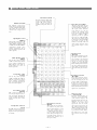
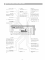
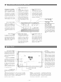
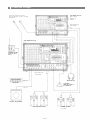
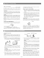
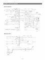
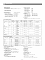
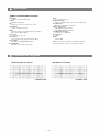
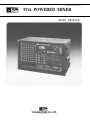
Operating Instruction Manual
TOA POWERED MIXER
Model MCX-106
TOA ELECTRIC CO., LTD.
KOBE, JAPAN
Contents
General Description
Features
Front Panel [Input Section]
Front Panel [Output Section]
Front Panel [Stereo Cassette Recorder Section]
Front Panel [Patch Bay & Bus Link]
Rear Panel
Connection Examples
Input Connections
How to get a good mix.
Recording Level Setting
Type of Cassette Tape
Maintenance of Stereo Cassette Deck
Block and Level Diagrams
Specifications
Characteristic Diagrams
Appearance
Precautions
2. Description of components and functions on the
MCX-106.
D e s c r i p t i o n s may v a r y , d e p e n d i n g on each m a n u f a c t u r e r . In our O p e r a t i n g and I n s t r u c t i o n Manual
e x p l a n a t i o n of c o m p o n e n t s and f u n c t i o n s is made
a c c o r d i n g t o our usage f o r t h e m .
1. XLR Type Audio Connector
The connectors are wired as follows.
The pin 1 is ground ( s h i e l d ) , t h e pin 2 cold (low,
m i n u s ) , the pin 3 hot (high, p l u s ) .
MCX-106™ Operating Guide
6.
7.
8.
9.
10.
A Few Words about design:
The MCX™ is q u i t e an u n u s u a l p r o d u c t , b u t t h e
reasoning behind its design was q u i t e simple . . . . we
wanted to i n t e r g r a t e all t h e basic c o m p o n e n t s of a
sound reinforcement system and a recording s t u d i o
i n t o a single, t r a n s p o r t a b l e package.
The
1.
2.
3.
4.
5.
One-octave equalizer.
Patch bay.
Headphone c u e / m o n i t o r s y s t e m .
Three-hundred w a t t power a m p l i f i e r .
Road case.
Each of t h e s e " c o m p o n e n t s " f u n c t i o n s i n d e p e n d e n t l y
of t h e o t h e r s , a l t h o u g h some do share common signal
processing and c o n t r o l c i r c u i t r y . For example, t h e
main mixer, e f f e c t s m i x e r , and recording mixer all
m a k e use of t h e same i n p u t e q u a l i z a t i o n on each of t h e
six c h a n n e l s . And t h e i n p u t t r i m c o n t r o l p e r f o r m s t h e
same f u n c t i o n for a l l f o u r m i x i n g s e c t i o n s .
basic components of the MCX™ are as f o l l o w s :
Six-channel main mixer.
Six-channel o n - s t a g e m o n i t o r mixer.
Six-channel special e f f e c t s mixer.
Six-channel recording mixer.
Stereo t a p e deck.
— 1 —
General Description
The MCX-106 is a compact self-powered mixer with a Microprocessor c o n t r o l l e d stereo
cassette deck, designed to allow recording a live demo tape, p e r f o r m i n g to pre-recorded
program m a t e r i a l , recording sound on sound with an e x t e r n a l tape source, and
simultaneously performing as a six-channel "powered" main sound system and a sixchannel independent m o n i t o r mixer.
The MCX-106 fe a tu re s: six i n p u t channels, a 300 w a t t power a m p l i f i e r , 9-band graphic
equalizer, a u t o m a t i c compressor, reverb e f f e c t , f l u o r e s c e n t b a r g r a p h m e t e r , power
a m p l i f i e r p r o t e c t i o n c i r c u i t r y , and a c o m p l e t e p a t c h bay.
Each input channel features: i n p u t t r i m c o n t r o l w i t h LED peak i n d i c a t o r , pre-EQ f o l d b a c k
send, 3-band EQ, post-EQ recording level and pan controls, p o s t - r e v e r b / e f f e c t s send, LoZ balanced XLR input and Hi-Z unbalanced 1/4" i n p u t .
The built-in cassette deck f e a t u r e s : f u l l logic cassette mechanism c o n t r o l , dbx noise
reduction system, zero r e t u r n and cue f u n c t i o n s , a u t o m a t i c tape selector.
All these u n i q u e f u n c t i o n s are i n t e g r a t e d into a ruggedly c o n s t r u c t and p o r t a b l e package,
offering unlimited applications for school, church, band, performing group, etc.
The MCX-106 is a "first of its kind" product, providing such a wide variety of versatility.
Features
Each Channel
1. Built-in Stereo Cassette Recorder with microprocessor control
1. Input Trim Control with LED peak indicator
2. Six Input Channels
2. Pre-EQ f o l d b a c k send
3. 300 watt Power A m p l i f i e r
3. 3-Band EQ
4. 9-band Graphic Equalizer with Bypass Switch
4. Post-EQ recording level and pan controls
5. Auto-Comp™ Compression Circuitry with LED
indicator
5. Post r e v e r b / e f f e c t s send
6. Lo-Z Balanced XLR Input
6. Reverberation Effect with 2-band dedicated EQ
7. Hi-Z Unbalanced 1/4" I n p u t
7. Fluorescent Bargraph Metering— assignable
Stereo Cassette Recorder
8. Power Amp Protection Circuitry with indicator
1. Full Logic Cassette Mechanism Control
9. Complete patch Bay with Buss-Link™
10. Aux. Input with Stereo Balance and Level
Controls — assignable to PGM, FB, and Rec L & R
Busses
2. dbx® Noise Reduction System
11. Headphone Monitoring/Cueing System
4. Headphone O u t p u t w i t h Level Control
12. Independent Stage Monitor (FB) Mix
5. Tape Transport Remote Control ( s t a r t / s t o p )
3. A u t o m a t i c Tape Selector with Indicator (normal,
CrO 2 Metal)
6. Tape Pitch Control (±10%)
7. Zero R e t u r n w i t h A u t o m a t i c Cue
8. 3-Digit Tape C o u n t e r
—2—
Front Panel, Input Section
Foldback Control (FB)
The Foldback control determines the level of signal assigned to the foldback mixing buss,
thus s e t t i n g the level of t h a t
channel in t h e on-stage m o n i t o r
mix.
Peak Indicator (PEAK)
The peak i n d i c a t o r lights when
t h e pre or post EQ signal level
reaches 3dB below c l i p p i n g ,
giving a visual reference for
o p t i m u m s e t t i n g of t h e t r i m control.
High Equalizer Control
(HIGH EQ)
The high EQ control alters the
high frequency response of t h e
i n p u t channel, providing ±13dB
at 10kHz, and ±15dBat 20kHz of
continuously variable a c t i v e
shelving equalization. The "0"
detented position provides f l a t
audio response.
Recording pan Pot
(REC PAN)
This control assigns t h e recording signal from each channel to
Middle Equalizer Control
(MID EQ)
The mid EQ control provides
±15dB of c o n t i n u o u s l y variable
t h e recording L and R mixing
busses. At the center position,
t h e pan pot routes the signal
equally to the L and R mixing
busses. Panning from one side to
t h e other gradually assigns t h e
i n p u t signal to e i t h e r the recording L or R mixing bus exclusively!
active peaking e q u a l i z a t i o n at
2kHz. and has a flat audio response when set to t h e "0"
detented position.
Low Equalizer Control
(LOW EQ)
The low EQ control provides
±13dB at l00Hz and ±15dB at
50Hz (of c o n t i n u o u s l y v ariable
a c t i v e shelving e q u a l i z a t i o n .
The "0" detented position provides f l a t audio response.
Recording Level J Control
(REC LEVEL)
This control a d j u s t s the level of
signal assigned t o t h e tape deck
v i a t h e recording pan pot and
stereo L and R recording busses.
R o t a t i n g t h e control clockwise
increases t h e a m o u n t of signal
assigned to t h e recording L and R
busses and t h u s the level of t h a t
i n p u t in t h e "recording mix."
Reverb/Effects Control
(REV/EFF)
This c o n t r o l d e t e r m i n e s the?
level of signal assigned to the reverb effects buss. R o t a t i n g the
c o n t r o l clockwise increases t h e
a m o u n t of reverb e f f e c t in t h a t
channel.
Low Impedance Connectors
(LOW Z)
The XLR connectors are low impedance, e l e c t r o n i c a l l y balanced
i n p u t s w i t h an i n p u t impedance
of 1k ohms.
Input Trim Control (TRIM)
The i n p u t t r i m a d j u s t s the gain
of t h e head-amp stage of the associated channel, providing 39
dB of gain c o n t r o l . When t h e
t r i m c o n t r o l is set to t h e "10"
p o s i t i o n , t h e n o m i n al i n p u t
levels of t h e low-Z and high-Z
i n p u t s are — 55dB and —35dB respectively. At t h e "0" position
the levels are -16dB and +4dB.
The t r i m of each channel should
be a d j u s t e d so t h a t the peak LED
j u s t begins to l i g h t , or only
flashes occasionally. This will
ensure lowest d i s t o r t i o n levels
and o p t i m u m signal to noise
ratio.
High Impedance Connectors
(HIGH Z)
These connectors are u n b a l a n c ed, s t a n d a r d 1/4" phone j a c k s
w i t h an i n p u t impedance? of 50k
ohms, and an i n p u t level of
—35dB when t h e t r i m c o n t r o l is
set t o "10". When a plug is i n s e r t ed i n t o t h e high —Z i n p u t , t h e corresponding XLR c o n n e c t o r is
a u t o m a t i c a l l y s w i t c h e d o u t of
the i n p u t c i r c u i t r y .
— 3 —
Input Level Control
(INPUT LEVEL)
The level c o n t r o l provides cont i n u o u s l y variable adjustment
of t h e c h a n n e l o u t p u t to t h e
program mixing buss, thus det e r m i n i n g t h e level of t h a t
c h a n n e l in t h e main sound
s y s t e m mix. Since t h e reverb/
e f f e c t s signal is "post" t h i s control, an increase in t h e level of t h e
channel's o u t p u t w i l l also result
in a corresponding increase in
he reverb e f f e c t of t h a t channel.
The n o m i n a l level of the i n p u t
level c o n t r o l is at t h e "10" position.
Front Panel, Output Section
Aux Recording Balance
(AUX REC BAL)
This c o n t r o l a d j u s t s t h e level
balance of t h e a u x in, L and R
signals r o u t e d t o t h e L and R
m i x i n g busses.
At t h e center p o s i t i o n , t h e balance control routes the signal
e q u a l l y to t h e L and R m i x i n g
busses.
Auxiliary Input Recording
Level Control
(AUX REC LEVEL)
This control sets t h e level of
stereo L and R signal ( f r o m an
e x t e r n a l source connected to t h e
AUX INPUT) assigned to t h e recording busses, via t h e AUX
REC BAL control.
Auxiliary Input to
Foldback Control
((AUX TO FB)
This control sets the level of aux
i n p u t signal assigned to the foldback mixing bus, and t h u s t h e
level of the e x t e r n a l aux source
in t h e on-stage m o n i t o r mix.
NOTE: If t h e aux source is a
stereo L and R signal (for
example, a stereo cassette player) t h e L and R
will be combined i n t o
one mono signal before
assignment to either the
FB or PGM mixing busses.
Reverberation High Equalizer —
Control
(REV HIGH EQ)
The high EQ c o n t r o l a l t e r s t h e
high frequency response? of t h e
r e v e r b e r a t i o n s i g n a l . The "0" det e n t e d p o s i t i o n provides f l a t
a u d i o response.
Recordig Level Control
(EFF REC LEVEL)
- Reverberation Low Equalizer
Control
(REV LOW EQ)
The low EQ c o n t r o l a l t e r s t h e
low f r e q u e n c y response of t h e
r e v e r b e r a t i o n s i g n a l . The "0" det e n t e d p o s i t i o n provides f l a t
audio response.
- Playback to Program Control
(TAPE TO PGM)
This c o n t r o l a d j u s t s t h e level of
p l a y b a c k signal r o u t e d t o t h e
program m i x i n g buss, and t h u s
the level of t h e i n t e r n a l tape?
source in t h e m a i n m i x .
This c o n t r o l sets t h e level of
reverb (or e x t e r n a l e f f e c t s ) in
t h e recording mix, via the e f f e c t s
return pan pot.
Effect Recording Pan Control
(EFF REC PAN)
Playback to Foldback Control
(TAPE TO FB)
This c o n t r o l a d j u s t s t h e level of
This c o n t r o l assigns t h e reverb
or external effects signal to t h e
recording L and R mixing busses. In t h e center "detended"
p o s i t i o n , the signal is assigned
e q u a l l y to L and R; panning t h e
c o n t r o l g r a d u a l l y assigns t h e
e f f e c t t o either bus exclusively.
p l a y b a c k signal t o t h e f o l d b a c k
m i x i n g buss, and t h u s t h e level
of t h e i n t e r n a l t a p e in t h e onstage m o n i t o r mix.
Reverb/Effects to ProgramControl
(EFF TO PGM)
This control a d j u s t s t h e a m o u n t
of r e v e r b / e f f e c t s signal t h a t is
r e t u r n e d t o t h e program buss
and t h u s t h e level of reverb/
e f f e c t s c o n t a i n e d in t h e main
sound system.
Reverb/Effects Send Control
(REV/EFF SEND)
This c o n t r o l a d j u s t s t h e overall
signal level of t h e e f f e c t s mix
t h a t is delivered t o t h e i n t e r n a l
reverberation u n i t , or to an
e x t e r n a l e f f e c t s device t h r o u g h
t h e e f f e c t s o u t p u t . The send cont r o l works in c o n j u n c t i o n w i t h
t h e REV/EFF t o PGM and t h e
REV/EFF to FB controls to set
t h e overall level of reverb/
e f f e c t s in t h e main and m o n i t o r
sound systems.
The FB m a s t e r c o n t r o l a d j u s t s
t h e o v e r a l l combined signal
level of the six independent
channel foldback sends, and
t h u s t h e level of t h e e n t i r e onstage m o n i t o r mix.
Program Master Control (PGM)
The PGM c o n t r o l a d j u s t s t h e
overall combined signal level of
t h e six independent channel
level controls, and t h u s the level
of t h e m a i n sound system.
Graphic Equalizer
(EQUALIZATION)
The graphic equalizer is 1/1
octave w i t h 9 independent active
bands ( f i l t e r s ) , providing 12dB
of boost or cut at each center frequency. The "0" d e t e n t e d posit i o n provides f l a t audio response.
Graphic Equalizer In/Out
Switch (IN/OUT)
The i n / o u t switch enables comparison between a flat response
( o u t ) and t h e equalized response
( i n ) . The "out" position completely removes the equalizer
from t h e MCX-106 circuitry.
Phones Level Control
(PHONES)
The phones level c o n t r o l
a d j u s t s both the recording L
and R signals fed to t h e phones
o u t p u t and p e r m i t s recording
and p l a y b a c k m o n i t o r i n g .
Auxiliary Input to Program
Control
(AUX TO PGM)
This c o n t r o l sets t h e level of aux
i n p u t signal assigned to t h e
program mixing bus, and t h u s
the level of the external aux
source in the main mix.
Effect to Foldback Control
(EFF TO FB)
This control determines t h e
level of reverb/effects r e t u r n
signal assigned to t h e foldback
mixing buss, and t h u s t h e
amount of e f f e c t s in the on-stage
m o n i t o r mix.
Foldback Master Control (FB)
Headphone Jack
The headphone jack will accept
any stereo headphone w i t h 8
ohms impedance, or higher.
Buss Link Jack (BUSS LINK)
Patching Jack (PATCH BAY/OUT)
Patching Jack (PATCH BAY/IN)
Tape Deck Remote Control
(TAPE REMOTE)
This j a c k remotely operates t h e
tape PAUSE f u n c t i o n d u r i n g
recording or playback by means
of a foot switch.
-Aux Input L and R
(AUX IN, L, R)
The aux L and R 1/4" phone
jacks are unbalanced and a c c e p t
low and high impedance sources
at n o m i n a l —20 dB level. The
jacks are wired w i t h t h e corresponding L and R pin jacks in
parallel. When a plug is i n s e r t e d
in t h e phone ja c k , th e pin ja c k is
a u t o m a t i c a l l y switched out of
Playback Output Pin Jack
(TAPE OUT)
The playback o u t pin j a c k
o b t a i n s i t s signal from t h e
i n t e r n a l tape deck. Nominal
o u t p u t level is 0dB dB w i t h an
impedance o f 1k ohms.
t h e aux i n p u t c i r c u i t r y . The a u x
i n p u t is i n t e n d e d p r i m a r i l y for
e x t e r n a l m u s i c sources such as
cassette t a p e players, radio
receivers, or record players.
NOTE: A phonograph w i t h
m a g n e t i c c a r t r i d g e requires the use of a p r e amp w i t h RIAA e q u a l i zation.
Recording Output Pin Jack(REC OUT)
The REC out pin j a c k derives i t s
signal from t h e recording L and
R m i x i n g busses, and is i n t e n d e d
for c o n n e c t i o n t o e x t e r n a l r e cording e q u i p m e n t . N o m i n a l
o u t p u t level is —10 dB w i t h an
impedance o f 1k ohms.
—4—
Power Amp CompressionIndicator (COMP)
The comp LED l i g h t s when t h e
i n t e r n a l compressor is a c t i v a t ed. The compressor is p r o v i d e d
to p r o t e c t speaker systems by
compressing t h e i n p u t signal
level of t h e power a m p l i f i e r
when clipping occurs in the o u t p u t stage. Frequent f l a s h i n g of
t h e LED is not reason for a l a r m .
H o w e v e r . a c o n s t a n t or s t e a d y
l i g h t i n d i c a t e s t h a t t h e MCX-106
is b e i n g overdriven and t h a t t h e
i n t e r n a l power a m p l i f i e r is possibly "under powered" (or t h a t
a p p l i c a t i o n . The o u t p u t l e v e l of
t h e ; MCX-106 should be; decreased u n t i l the LED o nly flashes
intermittently.
Power Amp Protection
Indicator (PROTECT)
The indicator LED lights if t h e
power a m p l i f i e r o u t p u t is shorted, if the t e m p e r a t u r e of the u n i t
rises above acceptable levels, or
if DG is d r i f t e d to the speaker
o u t p u t s . If t h e LED should l i g h t ,
speaker wiring and ambient
t e m p e r a t u r e of t h e MCX-106
should be checked. If the LED
remains l i g h t e d , the u n i t should
be referred to q u a l i f i e d service
personnel for repair.
Note:
The MCX-106 p r o t e c t i o n circ u i t r y w i l l (1) detect ' f a u l t y cond i t i o n s ' w i t h i n t h e power ampl i f i e r , ( 2 ) give a visual indication,
and (3) a u t o m a t i c a l l y shut down
u n t i l t h e ; f a u l t condition is
a l l e v i a t e d . This special c i r c u i t r y
e n s u r e s maximum reliability
and v i r t u a l l y eliminates equipm e n t damage due t o unsafe or
f a u l t conditions. Please refer t o
f a u l t p r o t e c t i o n t a b l e on page 9
for f u l l e x p l a n a t i o n of t h i s
important feature.
Front Panel Stereo Cassette Deck Section
Counter Reset Button
Resets the tape couter t o "000".
Tape Counter
Indicates how far t h e tape has
travelled.
Tape Indicator
Indicates the type of t a p e used.
(The deck a u t o m a t i c a l l y selects
the type of tape. NORMAL,
CrO2, METAL)
Cassette Receptacle
Cue Indicator
R e m a i n s l i t d u r i n g o p e r a t i o n of
t h e Cue f u n c t i o n .
DBX Indicator
L i g h t s when t h e dbx noise;
r e d u c t i o n c i r c u i t r y is a c t i v a t e d .
Zero Return Switch
This s w i t c h selects t h e zero
r e t u r n f u n c t i o n . In t h e "on"
p o s i t i o n t h e t a p e w i l l rewind
and stop at any point on t h e t a p e
t h a t you d e s i g n a t e as "zero".
Pitch Control
(PITCH CONTROL)
Varies the tape transport speed
during playback by ±10%.
Mute Button
Pressing and holding the m u t e
b u t t o n during tape travel (while
in the recording mode) will
provide a "silent" section on t h e
tape for use w i t h the cuing
f u n c t i o n ; releasing t h e b u t t o n
will restore selected recording
levels. It is essential t h a t the
"muted" section c o n t i n u e for at
least four seconds to enable t h e
cue f u n c t i o n to operate correctly.
Recording Button
Pressing b o t h t h e PLAY and t h i s
b u t t o n p u t s u n i t in t h e recording
mode.
enables or disenables t h e i n t e r nal dbx noise r e d u c t i o n f e a t u r e
in e i t h e r t h e playback or
recording modes.
Cue Button
Pressing t h i s b u t t o n and the
FAST FORWARD or REWIND
b u t t o n w i l l rewind t h e tape t o
t h e n e x t "muted" or unrecorded
s e c t i o n ( t a p e silence of f o u r
seconds or more), where t h e
deck w i l l a u t o m a t i c a l l y stop.
Level Meter Selector Switch
The l e f t position monitors the
PGM and FB o u t p u t levels; t h e
right position monitors the
i n t e r n a l t a p e p l a y b a c k and
recording levels.
Eject Button (EJECT)
Ejects the tape.
Pause Button
This b u t t o n is used t o stop t h e
t a p e t r a v e l t e m p o r a r i l y during
recording or playback.
DBX Button
Pressing t h i s b u t t o n a l t e r n a t e l y
Fluorescent Bargraph Meter
The high i n t e n s i t y meters enable
v i s u a l m o n i t o r i n g of t h e o u t p u t
signals selected w i t h t h e Level
Meter Selector Switch.
Recording Level Sliders
Sets t h e overall signal level of
t h e stereo L and R recording
busses d u r i n g t h e recording
process; t h i s includes t h e level
assigned t o t h e ; REC OUT jacks
as well as t h e ; i n t e r n a l tape deck.
Rewind Button
Rewinds t h e t a p e at high speed.
Fast Forward Button
Advances t h e ; t a p e at highspeed.
Stop Button
Stops t h e t a p e m o t i o n .
Playback Button
This b u t t o n is used t o p l a y b a c k
t h e tape;.
— 5 —
Front Panel, Patch Bay & Buss Link
Effects Return Jack (EFT/RET)
The EFF/RET j a c k is provided t o
connect an e x t e r n a l e f f e c t s
device to t h e MCX-106. When a
plug is inserted t h e i n t e r n a l
r e v e r b e r a t i o n u n i t is a u t o m a t i cally s w i t c h e d o u t of t h e MCX106 c i r c u i t r y , being replaced by
the e x t e r n a l u n i t . This j a c k
should be connected to t h e o u t p u t of the e x t e r n a l e f f e c t s u n i t .
N o m i n a l i n p u t level is —20dB
w i t h an impedance of 50k ohms.
Graphic Equalizer Input Jack
(GEQ)
The GEQ i n p u t j a c k allows t h e
graphic e q u a l i z e r t o be used independently of t h e MCX-106
w i t h other external equipment,
or t h e i n t e r n a l power a m p l i f i e r
and t h e g r a p h i c e q u a l i z e r w i t h
e x t e r n a l e q u i p m e n t . When a
plug is i n s e r t e d , t h e m a i n mix
from t h e program buss is disconnected from t h e g r a p h i c e q u a l izer and t h e power a m p l i f i e r .
The n o m i n a l i n p u t level is —4dB
w i t h an i n p u t impedance of 50k
ohms.
Power Amplifier Input Jack
(PWR)
The PWR Amp i n p u t j a c k allows
t h e i n t e r n a l power a m p l i f i e r t o
be used w i t h e x t e r n a l e q u i p m e n t . When a p l u g is i n s e r t e d ,
t h e power amp is a u t o m a t i c a l l y
disconnected from t h e MCX-106
m i x e r s e c t i o n . The n o m i n a l inp u t level is +4dB w i t h an i n p u t
i m p e d a n c e of 10k ohms.
Program Buss Link Jack
(PGM) (+4dB 22k )
Fold Back Buss Link (FB)
(+4dB 22k )
Effects Output Jack (EFF)
The EFF Out j a c k used in conj u n c t i o n w i t h t h e EFF/RET Jack
allows use of an e x t e r n a l e f f e c t s
device in place of t h e i n t e r n a l
Reverb/Effects Buss Link Jack
(EFF) (+4dB 22k )
Buss Link Jacks
The buss l i n k provides direct
access t o t h e PGM, FB, and eff e c t s m i x i n g busses, and is provided for easy i n p u t expansion
w i t h a d d i t i o n a l MCX-106 u n i t s
or o t h e r a u x i l i a r y equipment.
All jacks have an i n p u t level of
+4dB w i t h an impedance of 22k
ohms.
reverberation u n i t . The e f f e c t s
o u t j a c k should be connected to
t h e i n p u t of t h e e x t e r n a l e f f e c t
u n i t . Nominal o u t p u t level is
— l 0 d B w i t h an impedance of 600
ohms.
Program Output Jack (PGM)
The PGM Out jack is provided
for connection to e x t e r n a l equalizers and/or power amps, deriving i t s signal prior to t h e i n t e r n a l
GEQ and power amp. N o m i n a l
o u t p u t level is +4dB w i t h an
impedance of 600 ohms.
- Foldback Output Jack (FB)
- Graphic Equalizer Output Jack
(GEQ)
This j a c k allows t h e MCX-106
and t h e i n t e r n a l graphic equalizer to be used w i t h an e x t e r n a l
power a m p l i f i e r , or in c o n j u n c t i o n w i t h t h e GEQ in j a c k , t o be
used i n d e p e n d e n t l y of all o t h e r
MCX-106 c i r c u i t r y . N o m i n a l
o u t p u t level is +4dB w i t h an
i m p e d a n c e of 600 ohms
This j a c k is for c o n n e c t i o n t o
e x t e r n a l power a m p l i f i e r s a n d /
or e q u a l i z e r s for t h e o n - s t a g e
m o n i t o r i n g system. N o m i n a l
o u t p u t level is +4dB w i t h an
impedance of 600 ohms. I f t h e
i n t e r n a l power amp and e q u a l izer are t o be used for t h e onstage m o n i t o r s y s t e m , t h e FB
o u t p u t should be connected t o
the GEQ i n p u t j a c k .
Rear Panel
Power Switch (POWER) The power s w i t c h is a threep o s i t i o n t y p e w i t h the m i d d l e
position being the "off" position.
The MCX-106 should be o p e r a t ed in t h e s w i t c h p o s i t i o n w h i c h
produces t h e lowest a m o u n t of
system h u m .
Cord Wrap
The cord wrap is provided for
c o n v e n i e n t storage of t h e power
cord when t h e MCX-106 is not in
use.
Caution - The power cord should
a l w a y s be c o m p l e t e l y removed
from t h e cord wrap prior to
o p e r a t i o n of t h e u n i t . This w i l l
i n s u r e m a x i m u m cooling of t h e
MCX-106. For t h e same reason,
a d e q u a t e clearance should be
m a i n t a i n e d between the rear
panel and any o t h e r surface (4-6
inches should do). The v e n t s on
t h e b o t t o m and top of t h e MCX106 are also provided for convect i o n cooling. These vents should
be k e p t clear and open. Failure t o
do so may cause t h e r m a l s h u t down of t h e u n i t .
Speaker Jacks (SPEAKERS) The speaker o u t p u t s are s t a n d ard 1/4" phone j a c k s wired in
p a r a l l e l . Speaker cables (recommend at least #18 gauge w i r e )
should be connected b e t w e e n
t h e MCX-106 and t h e speaker
s y s t e m s prior t o a p p l y i n g power
to t h e u n i t .
Caution - The MCX-106 s h o u l d
never be o p e r a t e d i n t o less t h a n
a 2 ohm speaker load.
Earth Terminal (GND)
AC Power Cord
The power cord is t h e t h r e e - w i r e
t y p e w i t h proper g r o u n d i n g f a c i lities.
Caution - The g r o u n d pin s h o u l d
n o t be removed u n d e r a n y c i r c u m s t a n c e s . I f t h e MCX-106
m u s t be used w i t h o u t proper
grounding f a c i l i t i e s , a s u i t a b l e
g r o u n d i n g a d a p t e r s h o u l d be
AC Fuse
u t i l i z e d . O p e r a t i o n of t h e MCX106 w i t h proper g r o u n d i n g
t e c h n i q u e s w i l l r e s u l t in less
s y s t e m noise and g r e a t l y reduced shock h a z a r d .
Warning - To a v o i d p o s s i b l e
e q u i p m e n t damage and or personnel i n j u r y , t h e f u s e s h o u l d
a l w a y s b e replaced w i t h same
t y p e and r a t i n g . U s i n g i m p r o p e r
fuses will also void the warran-
— 6 —
t y . The MCX-106 s h o u l d a l w a y s
be d i s c o n n e c t e d f r o m AC o u t l e t
p r i o r t o c h a n g i n g fuses. If fuse
r e p e a t e d l y f a i l s , t h e u n i t should
be r e f e r r e d t o q u a l i f i e d service
personnel lor repair.
Connection Examples
Low Z i n p u t should be connected
w i t h low impedance (50 ohm ~ 600 ohm)
microphones
SUB MIXER (MCX-106)
B u i l t in Power
A m p l i f i e r for
Foldback
From Speaker Jack
on Rear Panel
MAIN MIXER (MCX-106)
WIRELESS TUNER
SUCH AS WT-02,
WT-06
From Speaker J a c k
on Rear Panel
HEAD PHONES
KEYBOARD
TAPE DECK
REMOTE CONTROL
FOOTSWITCH
MUSICAL INSTRUMENT
MAIN SPEAKER SYSTEM
SPEAKER SYSTEM
for f o l d b a c k
— 7 —_
_
Input Connections
Generally speaking, there are two rules to follow when connecting equipment outputs
to the inputs of other equipment.
1. Properly match the impedances of the outputs and inputs.
2. Connect low impedance outputs to high impedance inputs.
It goes without saying that not only input and output impedance matching but also
level matching should be taken into consideration. Each input channel of the MCX106 is provided with an input TRIM control, so the usable signal level range is very
wide. Input impedances and levels are shown in the following table.
INPUT SPECIFICATIONS
CONNECTION
INPUT
ACTUAL
LOAD
IMPEDANCE
CH1
LOW Z
OPEN
CH6
HIGH Z
FOR USE
WITH
NOMINAL
MICROPHONES
LOWER IMP
LINES
TRIM
POSITION
SENSITIVITY
(PGM OUTPUT
LEVEL +4dB)
MAX BEFORE
CLIP INPUT
LEVEL
10
-55dBm (1.38mV)
-34dBm (15mV)
0
-16dBm (123mV)
+1.7dB (0.94V)
10
-35dBm (13.8mV)
-14dBm (150mV)
+4dBm (1.23mV)
+20dB (7.75V)
CONNECTOR
XLR TYPE NC3F
PHONE JACK
0
AUX (L & R)
——
LOWER IMP,
LINES
-l0dBm (245mV)
+8dBm (1.9V)
PHONE JACK
RCA PIN JACK
EFF/RET
——
LOWER IMP,
LINES
-20dBm (77.5mV)
-2dBm (0.61V)
PHONE JACK
GEQ
——
LOWER IMP,
LINES
+4dBm (1.23V)
PHONE JACK
+4dBm (1.23V)
PHONE JACK
PWR
BUSS LINK
(PGM, FB, EFF)
——
——
+4dBm (1.23V)
LOWER IMP
LINES
+20 dBm (7.75V)
PHONE JACK
*Sensitivity is the level required to produce a program out level of +4dBm.
*0dBm is referenced to 0.775V RMS.
All XLR Type connectors are electronically balanced (transformer less). Phone jack is
unbalanced.
If the line going from one piece of equipment to another is long (more than 5m), we
recommend that balanced outputs be connected to balanced inputs.
As is described in the beginning of the Operating Instructions Manual, the connectors
of the MCX-106 are wired as follows: Pin 1 is ground (shield). Pin 2 is cold (low,
minus). Pin 3 is hot (high, plus).
—8 —
How to get a good mix
Before connecting other equipment to the Powered mixer,
check the impedance and level of both. If the impedances
and levels do not match, mixing will be very difficult and
the S/N ratio will also be adversely affected.
If the trim control is set as shown in the l e f t figure, the
i n p u t level controls can be set to the same position.
The input level controls are used in general between 6 and
8.
Each input channel of the MCX-106 is provided with a
TRIM control. Thorough understanding of the function of
a TRIM control will make mixing easier.
The peak indicator LED illuminates if the head amplifier
or equalizer is clipping. The gain of the head-amplifier
must be decreased by t u r n i n g the trim control counterclockwise.
The function of the TRIM control is to control the negative
feedback volume of the head-amp so that the gain of the
head-amp can also be changed. Because of this, enough
dynamic range, even for high level signals is ensured.
Also, the S/N ratio will be better by decreasing the gain of
the head-amp.
For example, a keyboard, a musical instrument and a
dynamic microphone with output levels of —l0dBm,
-20dBm and -40dBm respectively are connected to the
MCX-106.
Key Board in
—l0dBm level
Musical Instrument in
—20dBm level
Dynamic
Microphone in
-40dBm level
Fault Protection Table
Fault
Excessive current due to
overloads.
Short circuits
(less than 0.4-ohm)
Temperature rise of heat
sink
(more than 105°C)
DC drift
Protection
Indication
Current limiter activates at
less than 1 ohm.
Compressor
LED illuminates.
Current limiter activates,
input signal is lowered,
unit shuts down.
Input signal is lowered.
Unit shuts down.
Amp protection
LED illuminates.
Action
Remove excessive lords.
Minimum speaker loads 2ohm.
Check speaker
lines/systems for shorts.
Amp protection
LED illuminates.
Check for adequate
ventilation.
Input signal is lowered.
Unit shuts down.
Amp protection
LED illuminates.
Refer to qualified service
personnel.
Restoration
Automatic restoration
after normal loads are
obtained.
Turn off power switch.
Turn on into operational
loads.
Automatic restoration
after temperature
lowers (to 75° - 95°C)
A u t o m a t i c restoration
after normal bias is
regained.
Recording Level Setting
The following procedures are recommended f o r an
accurate and h i g h - q u a l i t y recording.
1. Place the level meter selection switch in the "Tape"
position.
2. Engage the noise r e d u c t i o n c i r c u i t r y by pressing t h e
dbx switch.
an "encode/decode" process, m e a n i n g t h a t any tape
t h a t is recorded w i t h dbx m u s t also be played back
w i t h dbx, to o b t a i n s a t i s f a c t o r y r e s u l t s . If the
recording must be p l a y e d on o t h e r e q u i p m e n t
w i t h o u t dbx c i r c u i t r y , we r e c o m m e n d t h a t the dbx
f e a t u r e not be used.
NOTE:
Using the internal dbx c i r c u i t r y will provide higher
q u a l i t y recordings with excellent "signal-to-noise"
characteristics. You will notice a drastic r e d u c t i o n
in audible "tape hiss" and a s i g n i f i c a n t increase in
dynamic range. However, the dbx noise r e d u c t i o n is
3. Press the record b u t t o n to p l a c e t h e deck in "record
pause" mode.
4. A d j u s t the L and R m a s t e r recording level sliders to
a level j u s t below the "red" in t h e b a r g r a p h meters.
5. Press PLAY b u t t o n to b e g i n r e c o r d i n g .
— 9 —
Types of Cassette Tape
Types of cassette tape
Type
C-30
openings with adhesive tape if you desire to erase or
record the tape at a later date.
m i c r o n : 1/1000mm
C-46
C-60
C-90
C-120
Tape t r a v e l h o u r
30 m i n .
46 min
6 Om i n .
90 m i n .
120 m i n .
Tape t h i c k n e s s
18 m i c r o n
18 m i c r o n
18 m i c r o n
12 m i c r o n
9 micron
Hints on Cassette Tape Handling
1. Tape Slack can cause the tape to twist or break.
When necessary, always t a k e up slack by inserting
a pencil or similar o b j e c t into the reel hub and
turning.
2. Winding the tape too t i g h t l y on the reel may cause
the tape to rotate u n e v e n l y ; in worst case, the tape
may bind and not wind f r o m reel to reel.
Before using a tape again a f t e r c o n t i n u o u s playback
or recording, lightly tap the cassette housing or both
sides, and if necessary, rewind the tape in either the
f a s t - f o r w a r d or re-wind mode.
CAUTION:
A C-120 tape is so thin t h a t it can be easily s t r e t c h e d ,
causing tape slack and possible entanglement around
the pinch roller and capstan. We do not recommend the
use of C-120 cassette tapes.
NOTE:
The MCX detects the type of tape ( N o r m a l , CrO 2 ,
Metal) when the cassette is inserted and the door is
latched, automatically selects the proper EQ and bias
settings, and gives a visual indication on the front
panel.
For highest quality recordings and extended dynamic
range, we recommend the use of metal tape whenever
possible.
Storing Tapes
Always store cassette tapes in their cases with a
protective insert over the exposed portion of the tape;
if not available, a t t a c h a "stopper" made f r o m paper as
SAVING YOUR RECORDINGS
Cassette tapes are provided with two break-out tabs
as shown in figure. To prevent accidental erasure or
shown in the illustration. To prevent damage or
degradation of recordings, always store tapes in
locations free from direct sunlight, high temperature
or humidity, and magnetic effects from other electrical
equipment, speaker systems, etc.
overtaping, break the tabs with a screw-driver or
similar tool and remove. You may cover the tab
Maintenance of Stereo Cassette Mechanism
Cleaning the tape heads
NOTE:
We recommend removal of the cassette receptacle door
prior to the cleaning operation; this will f a c i l i t a t e easy
access to all the inner workings of the tape t r a n s p o r t
assembly.
1. The cassette door opens when the EJECT b u t t o n is
pushed. A f t e r opening, press the door downward
(see illustration) to disconnect the "top mounted
3. Clean the rubber parts of the transport assembly
with cleaning f l u i d , or alcohol, and wipe dry with a
clean, soft cloth.
NOTE:
If a t r a n s p o r t " L u b r i c a n t " of any kind is used on the
metal parts, take care to avoid contact with rubber
parts.
CAUTION:
The tape heads and guides are c a r e f u l l y a d j u s t e d to
ensure smooth and accurate tape travel during both
recording and play back; DO NOT USE EXCESSIVE FORCE when cleaning: misalignment may
result.
We r e c o m m e n d t h r o u g h c l e a n i n g of the tape t r a n s p o r t
assembly a f t e r every f o u r to six hours of use to ensure
o p t i m u m recording and p l a y back p e r f o r m a n c e .
detents" which hold the door to the chassis. Now
pull outward and away f r o m the main assembly.
Place the door aside in a safe location for later
cleaning.
CAUTION:
To prevent damage to the t r a n s p o r t and head
assembly, use only c o t t o n swabs or a soft cloth for
the cleaning procedure.
Demagnetizing the tape heads
The recording head will become "magnetized" a f t e r
prolonged use. This r e s i d u a l m a g n e t i s m will degrade
and possibly d e s t r o y y o u r v a l u a b l e recordings by
adding u n w a n t e d noise and d i s t o r t i o n , so it is
necessary to f r e q u e n t l y " d e m a g n e t i z e " the heads.
There are m a n y i n e x p e n s i v e head demagnetizers
a v a i l a b l e ; f o l l o w t h e m a n u f a c t u r e r ' s d i r e c t i o n s for use.
2. Using any good grade of commercially available
tape cleaning f l u i d (or an acceptable s u b s t i t u t e such
as a l c o h o l ) , t h o r o u g h l y clean the tape heads, tape
guides, and all other metal parts in the tape path.
— 10 —
Block and Level Diagrams
BLOCK DIAGRAMS
LEVEL DIAGRAM
— 11 —
Specifications
MIXER SECTION
Maximum Voltage Gain
INPUT to PGM out
INPUT to EFF out
INPUT to FB out
INPUT to REC out
INPUT to GEQ out
AUX to PGM out
EFF/RET to PGM out
Frequency Response
+0, -3dB 30Hz~20kHz (HIGH Z input TRIM at "0" positio
Total Harmonic Distortion
0.05% +4dBm at 1kHz.
Hum and Noise (Open)
Equivalent Input Noise
Equivalent Input Noise
All level Controls Minimum
PGM Master at MAX and all
input level controls minimum
PGM Master at MAX and one
input level control at MAX
-130dBm (20Hz~20kHz
-133dBm (IHF A)
-102dBm (IHF A)
59dB
45dB
59dB
45dB
59dB
14dB
24dB
Equalization
63Hz ±12dB Peaking
125Hz ±12dB Peaking
250kHz ±12dB Peaking
500Hz ±12dB Peaking
1kHz ±12dB Peaking
-93dBm (IHF A)
-72dBm (IHF A)
2kHz ±12dB Peaking
4kHz ±12dB Peaking
8kHz ±12dB Peaking
16kHz ±12dB Peaking
Peak Indicators
Red LED on each input channel LED's turn on at 3dB below
clipping.
INPUT SPECIFICATIONS
CONNECTION
INPUT
ACTUAL
LOAD
IMPEDANCE
CH1
LOW Z
OPEN
CH6
FOR USE
WITH
NOMINAL
MICROPHONES
LOWER IMP
LINES
HIGH Z
TRIM
POSITION
SENSITIVITY
(PGM OUTPUT
LEVEL +4dB)
MAX BEFORE
CLIP INPUT
LEVEL
10
-55dBm (1.38mV)
-34dBm (15mV)
0
-16dBm (123mV)
+1.7dB (0.94V)
10
-35dBm ( 13.8m V)
-14dBm (150mV)
+4dBm (1.23mV)
+20dB (7.75V)
CONNECTOR
XLR TYPE NC3F
PHONE JACK
0
AUX (L & R)
LOWER IMP,
LINES
-l0dBm (245mV)
+8dBm (1.9V)
PHONE JACK
RCA PIN JACK
EFF/RET
LOWER IMP,
LINES
-20dBm (77.5mV)
-2dBm (0.61V)
PHONE JACK
GEQ
LOWER IMP,
LINES
+4dBm (1.23V)
PHONE JACK
PWR
LOWER IMP
LINES
+4dBm (1.23V)
PHONE JACK
BUSS LINK
(PGM, FB, EFF)
LOWER IMP
LINES
+4dBm (1.23V)
+20 dBm (7.75V)
PHONE JACK
OUTPUT SPECIFICATIONS
CONNECTION
ACTUAL LOAD
IMPEDANCE
FOR USE WITH
NOMINAL
NOMINAL
OUTPUT LEVEL
MAX. BEFORE
CLIP
CONNECTOR
+4dB (1.23V)
+20dB (7.75V)
PHONE JACK
+10dB (245V)
+8dB (1.9V)
PHONE JACK
IMP. LINES
+4dB (1.23V)
+20dB (7.75V)
PHONE JACK
FB
IMP. LINES
+4dB (1.23V)
+20dB (7.75V)
PHONE JACK
REC L & R
IMP. LINES
-l0dB (7.75V)
+8dB (1.9V)
RCA PIN JACK
TAPE L & R
IMP. LINES
0dB (0.775V)
+20dB (7.75V)
RCA PIN JACK
PGM
IMP. LINES
EFF
IMP. LINES
GEQ
POWER AMPLIFIER SECTION
Damping Factor
Greater than 200 (1kHz
Input Sensitivity
+4dBm (1.23V)
Input Impedance
Frequency Response
+0, -1dB 5Hz to 40kHz (200W RMS
Rated Power & Load
120W RMS
300W RMS
200W RMS
Power Output at Clipping
1% THD, 1kHz
140W RMS
348W RMS
238W RMS
Total Harmonic Distortion
Less than 0.1% (200mW~200W RMS, 20Hz~20kHz)
Typically below 0.05%
Compressor Dynamic Range
Greater than 26dB
Output Connector
Phone Jack X2
Power Requirement
600 W 120V AC 50/60Hz
Dimensions (WXHXD)
605X371X356mm (23.8X14.6 X14.0) inch
Weight
27.2 kg (60 I b s )
Hum and Noise
At least 110dB S/N ratio, 20Hz~20kHz
At least 113dB S/N ratio IHF-A weighted
*0dBm is referenced to 0.775V RMS.
Specifications are s u b j e c t to change w i t h o u t notice.
— 12 —
Specifications
STEREO CASSETTE DECK SECTION
Mechanism
1 Motor 3 Solenoid Mechanism
Control
4 Bit Micro Computer
Tape
Compact Cassette C-30, C-46, C-60 or C90
Track Format
4-Track, 2-Channel (Stereo)
Heads
2 Channel Stereo Recording/Play Back (Permalloy)
Erase (Ferrite Double Gap)
Tape Speed
1-7/8 ips (4.75 cm/s)±l%
Pitch Control
±10% of normal Tape Speed (Play Back Only)
Wow & Flutter
Less Than 0.08% RMS NAB Weighted
Fast Wind Time
Less Than 100 seconds (C-60 Tape)
Motor
Electronically Governor
Frequency Response
40 Hz to 12.5 kHz (Metal) (Overall Record/Playback)
Noise Reduction
*DBX type II (IN/OUT Switchable)
Signal to Noise Ratio
70dB *DBX IN 20 Hz~20 kHz
90 dB *DBX IN IHF-A Weighted
Total Harmonic Distortion
Less Than 3% at 1kHz 0dB
Bias Frequency
85kHz
Erasure
70 dB at 1kHz
*DBX is the registered trademark of DBX incorporated.
**Specifications are subject to change without notice.
Characteristics Diagrams
CASSETTE DECK PLAYBACK
RECORDING PLAYBACK
NORMAL TAPE
NORMAL TAPE
— 13 —
Characteristics Diagrams
HIGH Z IN. TRIM/MIN. & INPUT EQ
GEQ
POWER AMP POWER BAND WIDTH
POWER AMP TOTAL HARMONIC DISTORTION
POWER AMP COMPRESSOR
REVERBERATION FREQUENCY RESPONSE
Appearance
— 14 —
TOA ELECTRIC CO., LTD.
KOBE, JAPAN
Printed in Japan
133-02-690-80