1
FILE NO. A05-004-1
Revised: Jan./2006
SERVICE MANUAL
R410A
System air conditioner
The indoor units in the Super Heat Recovery Multi System are common to those used in the Super Modular Multi
System air conditioner. Therefore refer to the service manuals A03-009, A03-010, and A03-011 separately issued.
Heat Recovery Type
Indoor Unit
Outdoor Unit
4-way Air Discharge Cassette Type
MMU-AP0091H, AP0121H, AP0151H,
MMU-AP0181H, AP0241H, AP0271H,
MMU-AP0301H, AP0361H, AP0481H
MMU-AP0561H
2-way Air Discharge Cassette Type
MMU-AP0071WH, AP0091WH, AP0121WH,
MMU-AP0151WH, AP0181WH, AP0241WH,
MMU-AP0271WH, AP0301WH, AP0481WH*
* CHINA market only
1-way Air Discharge Cassette Type
MMU-AP0071YH, AP0091YH, AP0121YH,
MMU-AP0151SH, AP0181SH, AP0241SH,
MMU-AP0152SH, AP0182SH, AP0242SH
Inverter Unit
MMY-MAP0802FT8
MMY-MAP1002FT8
MMY-MAP1202FT8
Flow Selector Unit (FS unit)
RBM-Y1122FE
RBM-Y1802FE
RBM-Y2802FE
Concealed Duct Standard Type
MMD-AP0071BH, AP0091BH, AP0121BH, AP0151BH,
MMD-AP0181BH, AP0241BH, AP0271BH, AP0301BH,
MMD-AP0361BH, AP0481BH, AP0561BH
Concealed Duct High Static Pressure Type
MMD-AP0181H, AP0241H, AP0271H,
MMD-AP0361H, AP0481H
Slim Duct Type
MMD-AP0071SPH, AP0091SPH, AP0121SPH,
MMD-AP0151SPH, AP0181SPH
Under Ceiling Type
MMC-AP0151H, AP0181H, AP0241H,
MMC-AP0271H, AP0361H, AP0481H
High Wall Type
MMK-AP0071H, AP0091H, AP0121H,
MMK-AP0151H, AP0181H, AP0241H,
MMK-AP0072H, AP0092H, AP0122H
Floor Standing Cabinet Type
MML-AP0071H, AP0091H, AP0121H,
MML-AP0151H, AP0181H, AP0241H
Floor Standing Concealed Type
MML-AP0071BH, AP0091BH, AP0121BH,
MML-AP0151BH, AP0181BH, AP0241BH
Floor Standing Type
MMF-AP0151H, AP0181H, AP0241H,AP0271H,
MMF-AP0361H, AP0481H, AP0561H
PRINTED IN JAPAN, Jan., 2006 ToMo
WARNINGS ON REFRIGERANT LEAKAGE
Important
Check of Concentration Limit
The room in which the air conditioner is to be
installed requires a design that in the event of
refrigerant gas leaking out, its concentration will
not exceed a set limit.
The refrigerant R410A which is used in the air
conditioner is safe, without the toxicity or
combustibility of ammonia, and is not restricted by
laws to be imposed which protect the ozone layer.
However, since it contains more than air, it poses the
risk of suffocation if its concentration should rise
excessively. Suffocation from leakage of R410A is
almost non-existent. With the recent increase in the
number of high concentration buildings, however, the
installation of multi air conditioner systems is on the
increase because of the need for effective use of floor
space, individual control, energy conservation by
curtailing heat and carrying power etc.
Most importantly, the multi air conditioner system is
able to replenish a large amount of refrigerant
compared with conventional individual air conditioners.
If a single unit of the multi conditioner system is to be
installed in a small room, select a suitable model and
installation procedure so that if the refrigerant
accidentally leaks out, its concentration does not
reach the limit (and in the event of an emergency,
measures can be made before injury can occur).
In a room where the concentration may exceed the
limit, create an opening with adjacent rooms, or install
mechanical ventilation combined with a gas leak
detection device.
The concentration is as given below.
Total amount of refrigerant (kg)
Min. volume of the indoor unit installed room (m³)
≤ Concentration limit (kg/m³)
NOTE 2 :
The standards for minimum room volume are as
follows.
(1) No partition (shaded portion)
(2) When there is an effective opening with the
adjacent room for ventilation of leaking refrigerant
gas (opening without a door, or an opening 0.15%
or larger than the respective floor spaces at the
top or bottom of the door).
Outdoor unit
Refrigerant piping
Indoor unit
(3) If an indoor unit is installed in each partitioned
room and the refrigerant tubing is interconnected,
the smallest room of course becomes the object.
But when a mechanical ventilation is installed
interlocked with a gas leakage detector in the
smallest room where the density limit is exceeded,
the volume of the next smallest room becomes the
object.
Refrigerant piping
Outdoor unit
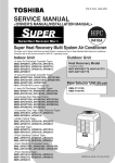
The concentration limit of R410A which is used in multi
air conditioners is 0.3kg/m³.
NOTE 1 :
If there are 2 or more refrigerating systems in a single
refrigerating device, the amounts of refrigerant should
be as charged in each independent device.
e.g., charged
amount (10kg)
Outdoor unit
e.g.,
charged amount (15kg)
Very
small
room
Indoor unit
Small
room
Medium
room
Large room
Mechanical ventilation device - Gas leak detector
NOTE 3 :
The minimum indoor floor area compared with the
amount of refrigerant is roughly as follows:
(When the ceiling is 2.7m high)
40
m² 35
Room A Room B Room C Room D Room E Room F
Indoor unit
For the amount of charge in this example:
The possible amount of leaked refrigerant gas in
rooms A, B and C is 10kg.
The possible amount of leaked refrigerant gas in
rooms D, E and F is 15kg.
Min. indoor floor area
30
25
Range below the
density limit
of 0.3 kg/m³
(countermeasures
not needed)
20
15
10
Range above
the density limit
of 0.3 kg/m³
(countermeasures
needed)
5
0
10
20
30
Total amount of refrigerant
kg
CONTENTS
SAFETY CAUTION ............................................................................................ 4
1. OUTLINE ................................................................................................... 9
2. WIRING DIAGRAM ................................................................................. 14
3. PARTS RATING ...................................................................................... 30
4. REFRIGERANT PIPING SYSTEMATIC DRAWING ............................... 48
5. SYSTEM REFRIGERANT CYCLE DRAWING ....................................... 53
6. CONTROL OUTLINE .............................................................................. 60
7. APPLIED CONTROL .............................................................................. 71
8. TEST OPERATION ................................................................................. 86
9. TROUBLESHOOTING .......................................................................... 116
10. CONFIGURATION OF CONTROL CIRCUIT ........................................ 174
11. BACKUP OPERATIONS (EMERGENCY OPERATION)....................... 188
12. OIL LEVEL JUDGMENT DISPLAY ....................................................... 190
13. REFRIGERANT RECOVERY
WHEN REPLACING THE COMPRESSOR ........................................... 191
14. LEAKAGE/CLOGGING OF OIL-EQUALIZATION CIRCUIT ................. 197
15. REPLACING COMPRESSOR............................................................... 199
16. REPLACING PROCEDURE OF PARTS ............................................... 206
17. P.C. BOARD .......................................................................................... 217
NOTE
Ensure power is isolated from the unit when replacing the high performance filter or when opening the
service panel.
SAFETY CAUTION
The important contents concerned to the safety are described on the product itself and on this Service Manual.
Please read this Service Manual after understanding the described items thoroughly in the following contents
(Indications/Illustrated marks), and keep them.
[Explanation of indications]
Indication
Explanation
DANGER
Indicates contents assumed that an imminent danger causing a death or serious injury of
the repair engineers and the third parties when an incorrect work has been executed.
WARNING
Indicates possibilities assumed that a danger causing a death or serious injury of the
repair engineers, the third parties, and the users due to troubles of the product after work
when an incorrect work has been executed.
CAUTION
Indicates contents assumed that an injury or property damage (∗) may be caused on the
repair engineers, the third parties, and the users due to troubles of the product after work
when an incorrect work has been executed.
∗ Property damage : Enlarged damage concerned to property, furniture, and domestic animal/pet
[Explanation of illustrated marks]
Mark
Explanation
Indicates prohibited items (Forbidden items to do)
The sentences near an illustrated mark describe the concrete prohibited contents.
Indicates mandatory items (Compulsory items to do)
The sentences near an illustrated mark describe the concrete mandatory contents.
Indicates cautions (including danger/warning)
The sentences or illustration near or in an illustrated mark describe the concrete cautious contents.
[Confirmation of warning label on the main unit]
Confirm that labels are indicated on the specified positions
(Refer to the Parts disassembly diagram (Outdoor unit).)
If removing the label during parts replace, stick it as the original.
DANGER
Turn off breaker.
Execute discharge
between terminals.
Turn “OFF” the breaker before removing the front panel and cabinet, otherwise an electric
shock is caused by high voltage resulted in a death or injury.
During operation, a high voltage with 400V or higher of circuit (∗) at secondary circuit of the highvoltage transformer is applied.
If touching a high voltage with the naked hands or body, an electric shock is caused even if using an
electric insulator.
∗ : For details, refer to the electric wiring diagram.
When removing the front panel or cabinet, execute short-circuit and discharge between highvoltage capacitor terminals.
If discharge is not executed, an electric shock is caused by high voltage resulted in a death or injury.
After turning off the breaker, high voltage also keeps to apply to the high-voltage capacitor.
Do not turn on the breaker under condition that the front panel and cabinet are removed.
An electric shock is caused by high voltage resulted in a death or injury.
Prohibition
4
WARNING
Check earth wires.
Before troubleshooting or repair work, check the earth wire is connected to the earth
terminals of the main unit, otherwise an electric shock is caused when a leak occurs.
If the earth wire is not correctly connected, contact an electric engineer for rework.
Do not modify the products.
Do not also disassemble or modify the parts. It may cause a fire, electric shock or injury.
Prohibition of modification.
Use specified parts.
Do not bring a child
close to the equipment.
For spare parts, use those specified (∗
∗).
If unspecified parts are used, a fire or electric shock may be caused.
∗: For details, refer to the parts list.
Before troubleshooting or repair work, do not bring a third party (a child, etc.) except
the repair engineers close to the equipment.
It causes an injury with tools or disassembled parts.
Please inform the users so that the third party (a child, etc.) does not approach the equipment.
Connect the cut-off lead cables with crimp contact, etc, put the closed end side
upward and then apply a water-cut method, otherwise a leak or production of fire is
caused at the users’ side.
Insulating measures
No fire
When repairing the refrigerating cycle, take the following measures.
1) Be attentive to fire around the cycle. When using a gas stove, etc, be sure to put out fire
before work; otherwise the oil mixed with refrigerant gas may catch fire.
2) Do not use a welder in the closed room. When using it without ventilation, carbon
monoxide poisoning may be caused.
3) Do not bring inflammables close to the refrigerant cycle, otherwise fire of the welder may
catch the inflammables.
Check the used refrigerant name and use tools and materials of the parts which
match with it.
For the products which use R410A refrigerant, the refrigerant name is indicated at a
position on the outdoor unit where is easy to see. To prevent miss-charging, the route of the
service port is changed from one of the former R22.
For an air conditioner which uses R410A, never use other refrigerant than R410A.
For an air conditioner which uses other refrigerant (R22, etc.), never use R410A.
If different types of refrigerant are mixed, abnormal high pressure generates in the refrigerating cycle and an injury due to breakage may be caused.
Refrigerant
Do not charge refrigerant additionally.
If charging refrigerant additionally when refrigerant gas leaks, the refrigerant composition in
the refrigerating cycle changes resulted in change of air conditioner characteristics or
refrigerant over the specified standard amount is charged and an abnormal high pressure is
applied to the inside of the refrigerating cycle resulted in cause of breakage or injury.
Therefore if the refrigerant gas leaks, recover the refrigerant in the air conditioner, execute
vacuuming, and then newly recharge the specified amount of liquid refrigerant. In this time,
never charge the refrigerant over the specified amount.
When recharging the refrigerant in the refrigerating cycle, do not mix the refrigerant
or air other than R410A into the specified refrigerant.
If air or others is mixed with the refrigerant, abnormal high pressure generates in the
refrigerating cycle resulted in cause of injury due to breakage.
After installation work, check the refrigerant gas does not leak.
If the refrigerant gas leaks in the room, poisonous gas generates when gas touches to fire
such as fan heater, stove or cocking stove though the refrigerant gas itself is innocuous.
Never recover the refrigerant into the outdoor unit.
When the equipment is moved or repaired, be sure to recover the refrigerant with recovering device. The refrigerant cannot be recovered in the outdoor unit; otherwise a serious
accident such as breakage or injury is caused.
Assembly/Cabling
After repair work, surely assemble the disassembled parts, and connect and lead the
removed cables as before. Perform the work so that the cabinet or panel does not
catch the inner cables.
If incorrect assembly or incorrect cable connection was done, a disaster such as a leak or
fire is caused at user’s side.
5
WARNING
Insulator check
Ventilation
After the work has finished, be sure to use an insulation tester set (500V mugger) to
Ω or more between the charge section and the non-charge
check the resistance is 2MΩ
metal section (Earth position).
If the resistance value is low, a disaster such as a leak or electric shock is caused at user’s
side.
When the refrigerant gas leaks during work, execute ventilation.
If the refrigerant gas touches to a fire, poisonous gas generates. A case of leakage of the
refrigerant and the closed room full with gas is dangerous because a shortage of oxygen
occurs. Be sure to execute ventilation.
When checking the circuit inevitably under condition of the power-ON, use rubber
gloves and others not to touch to the charging section.
If touching to the charging section, an electric shock may be caused.
Be attentive to
electric shock
When the refrigerant gas leaks, find up the leaked position and repair it surely.
If the leaked position cannot be found up and the repair work is interrupted, pump-down
and tighten the service valve, otherwise the refrigerant gas may leak into the room.
The poisonous gas generates when gas touches to fire such as fan heater, stove or cocking
stove though the refrigerant gas itself is innocuous.
Compulsion
When installing equipment which includes a large amount of charged refrigerant such
as a multi air conditioner in a sub-room, it is necessary that the density does not the
limit even if the refrigerant leaks.
If the refrigerant leaks and exceeds the limit density, an accident of shortage of oxygen is
caused.
For the installation/moving/reinstallation work, follow to the Installation Manual.
If an incorrect installation is done, a trouble of the refrigerating cycle, water leak, electric
shock or fire is caused.
After repair work has finished, check there is no trouble.
If check is not executed, a fire, electric shock or injury may be caused. For a check, turn off
the power breaker.
Check after rerair
Check after reinstallation
After repair work (installation of front panel and cabinet) has finished, execute a test
run to check there is no generation of smoke or abnormal sound.
If check is not executed, a fire or an electric shock is caused. Before test run, install the
front panel and cabinet.
Check the following items after reinstallation.
1) The earth wire is correctly connected.
2) The power cord is not caught in the product.
3) There is no inclination or unsteadiness and the installation is stable.
If check is not executed, a fire, an electric shock or an injury is caused.
CAUTION
Put on gloves
Cooling check
∗) during repair work.
Be sure to put on gloves (∗
If not putting on gloves, an injury may be caused with the parts, etc.
(∗) Heavy gloves such as work gloves
When the power was turned on, start to work after the equipment has been
sufficiently cooled.
As temperature of the compressor pipes and others became high due to cooling/heating
operation, a burn may be caused.
6
• New Refrigerant (R410A)
This air conditioner adopts a new HFC type refrigerant (R410A) which does not deplete the ozone layer.
1. Safety Caution Concerned to New Refrigerant
The pressure of R410A is high 1.6 times of that of the former refrigerant (R22). Accompanied with change of
refrigerant, the refrigerating oil has been also changed. Therefore, be sure that water, dust, the former refrigerant or the former refrigerating oil is not mixed into the refrigerating cycle of the air conditioner with new refrigerant during installation work or service work. If an incorrect work or incorrect service is performed, there is a
possibility to cause a serious accident. Use the tools and materials exclusive to R410A to purpose a safe work.
4. Tools
(1) Required Tools for R410A
Mixing of different types of oil may cause generation of sludge, clogging of capillary, etc.
Accordingly, the tools to be used are classified into the following three types.
1) Tools exclusive for R410A (Those which cannot be used for conventional refrigerant (R22))
2) Tools exclusive for R410A, but can be also used for conventional refrigerant (R22)
3) Tools commonly used for R410A and for conventional refrigerant (R22)
The table below shows the tools exclusive for R410A and their interchangeability.
Tools exclusive for R410A (The following tools for R410A are required.)
2. Cautions on Installation/Service
(1) Do not mix the other refrigerant or refrigerating oil.
For the tools exclusive to R410A, shapes of all the joints including the service port differ from those of the
former refrigerant in order to prevent mixture of them.
(2) As the use pressure of the new refrigerant is high, use material thickness of the pipe and tools which are
specified for R410A.
(3) In the installation time, use clean pipe materials and work with great attention so that water and others do
not mix in because pipes are affected by impurities such as water, oxide scales, oil, etc. Use the clean
pipes.
Be sure to brazing with flowing nitrogen gas. (Never use gas other than nitrogen gas.)
(4) For the earth protection, use a vacuum pump for air purge.
(5) R410A refrigerant is azeotropic mixture type refrigerant. Therefore use liquid type to charge the refrigerant.
(If using gas for charging, composition of the refrigerant changes and then characteristics of the air conditioner change.)
Tools whose specifications are changed for R410A and their interchangeability
R410A
air conditioner installation
No.
Usage
Used tool
Conventional air
conditioner installation
Existence of
Whether convenWhether new equipment
new equipment tional equipment can can be used with
for R410A
be used
conventional refrigerant
Flare tool
Pipe flaring
Yes
*(Note 1)
Yes
Copper pipe gauge for
adjusting projection
margin
Flaring by conventional
flare tool
Yes
*(Note 1)
*(Note 1)
Torque wrench
Connection of flare nut
Yes
No
No
Gauge manifold
Evacuating, refrigerant
charge, run check, etc.
Yes
No
No
Charge hose
7
3. Pipe Materials
Vacuum pump adapter
Vacuum evacuating
Yes
No
Yes
For the refrigerant pipes, copper pipe and joints are mainly used. It is necessary to select the most appropriate
pipes to conform to the standard. Use clean material in which impurities adhere inside of pipe or joint to a
minimum.
Electronic balance for
refrigerant charging
Refrigerant charge
Yes
Yes
Yes
Refrigerant cylinder
Refrigerant charge
Yes
No
No
Leakage detector
Gas leakage check
Yes
No
Yes
Charging cylinder
Refrigerant charge
(Note 2)
No
No
(1) Copper pipe
<Piping>
The pipe thickness, flare finishing size, flare nut and others differ according to a refrigerant type.
When using a long copper pipe for R410A, it is recommended to select “Copper or copper-base pipe without
seam” and one with bonded oil amount 40mg/10m or less. Also do not use crushed, deformed, discolored
(especially inside) pipes. (Impurities cause clogging of expansion valves and capillary tubes.)
<Flare nut>
Use the flare nuts which are attached to the air conditioner unit.
(2) Joint
The flare joint and socket joint are used for joints of the copper pipe. The joints are rarely used for installation of the air conditioner. However clear impurities when using them.
(Note 1) When flaring is carried out for R410A using the conventional flare tools, adjustment of projection
margin is necessary. For this adjustment, a copper pipe gauge, etc. are necessary.
(Note 2) Charging cylinder for R410A is being currently developed.
General tools (Conventional tools can be used.)
In addition to the above exclusive tools, the following equipments which serve also for R22 are necessary
as the general tools.
(1) Vacuum pump
Use vacuum pump by
attaching vacuum pump adapter.
(2) Torque wrench
(3) Pipe cutter
(4) Reamer
(5) Pipe bender
(6) Level vial
(7) Screwdriver (+, –)
(8) Spanner or Monkey wrench
(9) Hole core drill
(10) Hexagon wrench (Opposite side 4mm)
(11) Tape measure
(12) Metal saw
Also prepare the following equipments for other installation method and run check.
(1) Clamp meter
(3) Insulation resistance tester (Megger)
(2) Thermometer
(4) Electroscope (Volt meter)
5. Recharge of Refrigerant
When recharge of the refrigerant is required, charge the new refrigerant with the specified amount in the
procedure as described below.
Recover the refrigerant and check there is no refrigerant in the
equipment.
Leave it as it is for 1 to 2 minutes and check the indicator
of the compound gauge does not return.
Connect the charge hose to the packed valve service ports at gas
side, liquid side, and balance side of the outdoor unit.
Set the refrigerant cylinder on the electronic balance,
connect the charge hose to connecting ports of the
cylinder and the electronic gauge, and then charge the
liquid refrigerant from the service port at liquid side.
(Shield with the gauge manifold so that refrigerant does
not flow to gas side.)
Connect the charge hose to vacuum pump adaptor.
Open the packed valves of the balance pipe fully at liquid and gas
sides, and then return the valve at gas side a little to the closed side.
Open fully PMV of the outdoor unit.
• Turn on power of the outdoor unit.
• Short CN30 on I/F P.C. board of the outdoor unit.
• Turn off power of the outdoor unit within 2 minutes after shorting CN30.
(Charge the refrigerant as below.)
LowHighpressure gauge pressure gauge
Connected to
indoor unit
Valve fully closed
(gas side)
Main
Center unit
pipe
Open fully the handle on the Low side of the gauge manifold, and
then turn on the power of vacuum pump for vacuuming.
Brazed
Fully
tightened
When the pressure has lowered until indication of the compound
gauge pointed –0.1MPa (–76cmHg), open fully the handle Low and
turn off the power of vacuum pump.
Q
R
Q
R
Service
port
Ø6.4
Copper pipe
VL
VH Gauge
manifold
Reducing
valve
Service port
Valve fully closed
(liquid side)
Fully
tightened
Never charge the refrigerant over the specified amount.
Do not charge the additional refrigerant.
If charging refrigerant additionally when refrigerant gas
leaks, the refrigerant composition in the refrigerating cycle
changes resulted in change of air conditioner characteristics or refrigerant over the specified standard amount is
charged and an abnormal high pressure is applied to the
inside of the refrigerating cycle resulted in cause of
breakage or injury.
Nitrogen
gas
Ø6.4
Copper pipe
Valve fully closed
(balance)
Connected to other
terminal units
4mm-hexagonal wrench is required.
Set the equipment so that liquid refrigerant can be charged.
When using a cylinder with siphon pipe, liquid can be charged without inverting the cylinder.
[ Cylinder with siphon ]
[ Cylinder without siphon ]
Gauge manifold
Gauge manifold
OUTDOOR unit
Electronic
balance
6. Environmental concern
Refrigerant
cylinder
Refrigerant
cylinder
Siphon
OUTDOOR unit
Electronic
balance
R410A refrigerant is consisted with HFC mixed refrigerant.
Therefore if the refrigerant gas is charged, the composition
of the charged refrigerant changes and characteristics of
the equipment changes.
Use “Vacuum pump method” for an air purge (Discharge of air in the connecting pipe) in installation time.
• Do not discharge flon gas into the air to protect the earth environment.
• Using the vacuum pump method, clear the remaining air (Nitrogen, etc.) in the unit. If the air remains, the
pressure in the refrigerating cycle becomes abnormally high and an injury could occur through failure of
the product.
8
1. OUTLINE
“Super Heat Recovery Multi System” is a multi air conditioning system which enables each
indoor unit in a refrigerant line to independently select cooling or heating operation.
As it is able to operate simultaneously in cooling and heating modes, further heat recovery
becomes possible. This system is most suitable for a building etc. where cool and hot air are
mixed, such as a building where there are large temperature differences between rooms,
caused by the influence of daylight or where used in a server room and permanent cooling is
required.
Heating and cooling operation are automatically selected in individual unit;
You can save time for operation.
For example, when heating is required for early morning and cooling for daytime, a Flow Selector Unit provides
automatically a smooth selection of heating or cooling operation.
Therefore you can obtain a comfortable room environment without feeling somewhat out of place and moreover
you can save time to select heat/cool operation.
INFORMATION
The Super Heat Recovery Multi system is different from that of the conventional Multi air conditioner in several
ways such as the heating and cooling operations are mixed and only a part of the air conditioning system
operates in cooling function.
For this reason, the following table explains the operation modes of this air conditioner.
The following table explains the representation of the operation modes within this Manual.
Operation mode
Operation mode
Outline
1. All Cooling
All indoor units are under cooling operation only.
Outdoor heat exchanger (Main heat exchanger) is used as condenser.
2. All Heating
All indoor units are under heating operation only.
Outdoor heat exchanger (Main heat exchanger) is used as evaporator.
3. Simultaneous operation
MIU for simultaneous operation
3-1. Mainly cooling, partly
heating operation
Indoor units are under heating/cooling simultaneous operation with subjective cooling operation
Outdoor heat exchanger (Sub heat exchanger) is used as condenser.
3-2. Mainly heating, partly
cooling operation
Indoor units are under heating/cooling simultaneous operation with subjective heating operation
Outdoor heat exchanger (Main heat exchanger) is used as evaporator.
4. Defrost
Using the reversing operation of the 4-way valve, ice on the outdoor heat exchanger is dissolved
within single cooling cycle.
9
1-1. Component Multi Using High-efficiency Refrigerant R410A
1. Outdoor units
Inverter unit
Corresponding HP
Appearance
8 HP
10 HP
12 HP
MAP0802FT8
MAP1002FT8
MAP1202FT8
Cooling capacity (kW)
22.4
28.0
33.5
Heating capacity (kW)
25.0
31.5
37.5
13
16
20
Model name
Heat pump
MMY-
No. of connectable indoor units
2. Combination of outdoor units
Corresponding HP
Combined Model
MMY-
Cooling capacity (kW)
Heating capacity (kW)
Combined outdoor units
No. of connectable indoor units
16 HP
18 HP
20 HP
24 HP
26 HP
28 HP
30 HP
AP1602FT8
AP1802FT8
AP2002FT8
AP2402FT8
AP2602FT8
AP2802FT8
AP3002FT8
45.0
50.4
56.0
68.0
73.0
78.5
84.0
50.0
56.5
63.0
76.5
81.5
88.0
95.0
8 HP
10 HP
10 HP
8 HP
10 HP
10 HP
10 HP
8 HP
8 HP
10 HP
8 HP
8 HP
10 HP
10 HP
—
—
—
8 HP
8 HP
8 HP
10 HP
27
30
33
40
43
47
48
3. Branching joints and headers
Model name
RBM-BY53FE
Y-shape branching joint (∗3)
4-branching header (∗4)
8-branching header (∗4)
T-branch joint
∗1
∗2
∗3
∗4
∗5
∗6
Usage
Indoor unit capacity code (∗1)
Total below 6.4
RBM-BY103FE Indoor unit capacity code (∗1)
Total below 14.2
RBM-BY53E
Indoor unit capacity code (∗1)
Total below 6.4
RBM-BY103E
Indoor unit capacity code (∗1)
Total below 14.2
RBM-BY203FE Indoor unit capacity code (∗1)
Total below 25.2
RBM-BY303FE Indoor unit capacity code (∗1)
Total below 25.2
RBM-BY203E
Indoor unit capacity code (∗1)
Total below 25.2
RBM-BY303E
Indoor unit capacity code (∗1)
Total below 25.2
RBM-1043FE
Indoor unit capacity code (∗1)
Total below 14.2
RBM-2043FE
Indoor unit capacity code (∗1)
Total below 25.2
RBM-1043E
Indoor unit capacity code (∗1)
Total below 14.2
RBM-2043E
Indoor unit capacity code (∗1)
Total below 25.2
RBM-1083FE
Indoor unit capacity code (∗1)
Total below 14.2
RBM-2083FE
Indoor unit capacity code (∗1)
Total below 25.2
Appearance
For 3 piping
For 2 piping (∗5)
For 3 piping
For 2 piping (∗5)
For 3 piping
For 2 piping (∗5)
For 3 piping
RBM-1083E
Indoor unit capacity code (∗1)
Total below 14.2
RBM-2083E
Indoor unit capacity code (∗1)
Total below 25.2
BT13-FE
The following 3 types of T joint pipes are supplied as 1 set.
• Balance pipe (Ø9.5) × 1
• Liquid side
(Corresponded dia. Ø12.7 to Ø19.1) × 1
• Suction gas side
(Corresponded dia. Ø22.2 to Ø34.9) × 1
• Discharge gas side
(Corresponded dia. Ø19.1 to Ø22.2) × 1
For 2 piping (∗5)
“Capacity code” can be obtained from page 11, 12. (Capacity code is not actual capacity)
If the total capacity code value of indoor unit exceeds that of the outdoor unit, apply capacity code of the outdoor unit.
When using a Y-shape branching joint for 1st branching, select according to the capacity code of the outdoor unit.
Max. 6.0 capacity code in total can be connected.
This is used for branching to “cooling only” indoor unit.
Model names for outdoor described in this guide are shortened because of the space constraint.
10
4. Flow selector units (FS unit)
Model name
Usage
RBM-Y1121FE
Capacity rank for indoor unit : Type 007 to 030
RBM-Y1801FE
Capacity rank for indoor unit : Type 036 to 056
RBM-Y2802FE
Capacity rank for indoor unit : Type 018 to 096
Appearance
* Accessory part (Sold separately): Connection cable kit (RBC-CBK15FE), up to 15m.
5. Indoor units
Type
Appearance
Model name
MMU-AP0091H
4-way Air Discharge
Cassette Type
2-way Air Discharge
Cassette Type
1-way Air Discharge
Cassette Type
Concealed Duct
Standard Type
Capacity rank Capacity code
009 type
1
Cooling
capacity (kW)
Heating
capacity (kW)
2.8
3.2
MMU-AP0121H
012 type
1.25
3.6
4.0
MMU-AP0151H,
015 type
1.7
4.5
5.0
MMU-AP0181H
018 type
2
5.6
6.3
MMU-AP0241H
024 type
2.5
7.1
8.0
MMU-AP0271H
027 type
3
8.0
9.0
MMU-AP0301H
030 type
3.2
9.0
10.0
MMU-AP0361H
036 type
4
11.2
12.5
MMU-AP0481H
048 type
5
14.0
16.0
MMU-AP0561H
056 type
6
16.0
18.0
MMU-AP0071WH
007 type
0.8
2.2
2.5
MMU-AP0091WH
009 type
1
2.8
3.2
MMU-AP0121WH
012 type
1.25
3.6
4.0
MMU-AP0151WH
015 type
1.7
4.5
5.0
MMU-AP0181WH
018 type
2
5.6
6.3
MMU-AP0241WH
024 type
2.5
7.1
8.0
MMU-AP0271WH
027 type
3
8.0
9.0
MMU-AP0301WH
030 type
3.2
9.0
10.0
MMU-AP0481WH
(CHINA only)
048 type
5
14.0
16.0
MMU-AP0071YH
007 type
0.8
2.2
2.5
MMU-AP0091YH
009 type
1
2.8
3.2
MMU-AP0121YH
012 type
1.25
3.6
4.0
MMU-AP0151SH
015 type
1.7
4.5
5.0
MMU-AP0181SH
018 type
2
5.6
6.3
MMU-AP0241SH
024 type
2.5
7.1
8.0
MMU-AP0152SH
015 type
1.7
4.5
5.0
MMU-AP0182SH
018 type
2
5.6
6.3
MMU-AP0242SH
024 type
2.5
7.1
8.0
MMD-AP0071BH
007 type
0.8
2.2
2.5
MMD-AP0091BH
009 type
1
2.8
3.2
MMD-AP0121BH
012 type
1.25
3.6
4.0
MMD-AP0151BH
015 type
1.7
4.5
5.0
MMD-AP0181BH
018 type
2
5.6
6.3
MMD-AP0241BH
024 type
2.5
7.1
8.0
MMD-AP0271BH
027 type
3
8.0
9.0
MMD-AP0301BH
030 type
3.2
9.0
10.0
MMD-AP0361BH
036 type
4
11.2
12.5
MMD-AP0481BH
048 type
5
14.0
16.0
MMD-AP0561BH
056 type
6
16.0
18.0
11
Type
Concealed Duct
High Static
Pressure Type
Slim Duct Type
Under Ceiling Type
High Wall Type
Floor Standing
Cabinet Type
Floor Standing
Concealed Type
Floor Standing Type
Appearance
Model name
Capacity rank Capacity code
Cooling
capacity (kW)
Heating
capacity (kW)
MMD-AP0181H
018 type
2
5.6
6.3
MMD-AP0241H
024 type
2.5
7.1
8.0
MMD-AP0271H
027 type
3
8.0
9.0
MMD-AP0361H
036 type
4
11.2
12.5
MMD-AP0481H
048 type
5
14.0
16.0
MMD-AP0071SPH
007 type
0.8
2.2
2.5
MMD-AP0091SPH
009 type
1
2.8
3.2
MMD-AP0121SPH
012 type
1.25
3.6
1.0
MMD-AP0151SPH
015 type
1.7
4.5
5.0
MMD-AP0181SPH
018 type
2
5.6
6.3
MMC-AP0151H
015 type
1.7
4.5
5.0
MMC-AP0181H
018 type
2
5.6
6.3
MMC-AP0241H
024 type
2.5
7.1
8.0
MMC-AP0271H
027 type
3
8.0
9.0
MMC-AP0361H
036 type
4
11.2
12.5
MMC-AP0481H
048 type
5
14.0
16.0
MMK-AP0071H
007 type
0.8
2.2
2.5
MMK-AP0091H
009 type
1
2.8
3.2
MMK-AP0121H
012 type
1.25
3.6
4.0
MMK-AP0151H
015 type
1.7
4.5
5.0
MMK-AP0181H
018 type
2
5.6
6.3
MMK-AP0241H
024 type
2.5
7.1
8.0
MMK-AP0072H
007 type
0.8
2.2
2.5
MMK-AP0092H
009 type
1
2.8
3.2
MMK-AP0122H
012 type
1.25
3.6
4.0
MML-AP0071H
007 type
0.8
2.2
2.5
MML-AP0091H
009 type
1
2.8
3.2
MML-AP0121H
012 type
1.25
3.6
4.0
MML-AP0151H
015 type
1.7
4.5
5.0
MML-AP0181H
018 type
2
5.6
6.3
MML-AP0241H
024 type
2.5
7.1
8.0
MML-AP0071BH
007 type
0.8
2.2
2.5
MML-AP0091BH
009 type
1
2.8
3.2
MML-AP0121BH
012 type
1.25
3.6
4.0
MML-AP0151BH
015 type
1.7
4.5
5.0
MML-AP0181BH
018 type
2
5.6
6.3
MML-AP0241BH
024 type
2.5
7.1
8.0
MMF-AP0151H
015 type
1.7
4.5
5.0
MMF-AP0181H
018 type
2
5.6
6.3
MMF-AP0241H
024 type
2.5
7.1
8.0
MMF-AP0271H
027 type
3
8.0
9.0
MMF-AP0361H
036 type
4
11.2
12.5
MMF-AP0481H
048 type
5
14.0
16.0
MMF-AP0561H
056 type
6
16.0
18.0
12
n Remote controllers
Name
Wired remote controller
Simple wired remote controller
Weekly timer
CODE No.
SuMoTuWeTh Fr Sa
SET DATA SETTING TEST
TEST
UNIT No.
SETTING
R.C.
H
No.
PROGRAM1
˚C
˚F
PROGRAM2
ERROR
PROGRAM3
TEMP.
Appearance
ON / OFF
WEEKLY TIMER
FILTER
RESET TEST
Model name
TIMER SET
FAN
MODE
TIME
SWING/FIX
VENT
SET
CL
UNIT
RBC-AMT31E
RBC-AS21E
RBC-EXW21E
Wireless remote controller kit
Name
Receiver section
ADR
Receiver section
mounted separately
ADR
Receiver section
ADR
Appearance
Model name
RBC-AX2U (W)-E
RBC-AX22CE
TCB-AX21E
Type
4-way Air Discharge
Cassette type
Under Ceiling type
1-way Air Discharge Cassette
type (MMU-AP✽✽✽2SH Series)
Separate sensor type
Name
Central remote controller
ZONE
ALL
ZONE
GROUP
CODE
No.
1234
SET DATA
SETTING
R.C.
UNIT No.
TEST
No.
Appearance
GROUP
SELECT
ZONE
CL
SET
Model name
TCB-SC642TLE
Type
64 system center controller
13
1
CN304
(GRY) 2
3
RED
Motor drive
circuit
RY303
~
1 1
Fuse
T3.15A
250V~
+
Power
supply
circuit
P301
CN66 1
(WHI) 2
CN44 1
(BLN) 2
CN50
(WHI)
1 2 3 4 5
Earth screw
1 2
Parts name
Fan motor
Indoor temp sensor
Temp sensor
Temp sensor
Temp sensor
Louver motor
Drain pump motor
Float switch
Drain control relay
Pulse Motor Valve
CN60
(WHI)
CN81
(BLK)
CN40
(BLU)
CN41
(BLU)
1 2 3 4 5 6
1 2 3 4 5
1 2
1 2
1 2 3
1 2 3
CN61
(YEL)
T10 1 2 3 4 5 6
(Option)
(Fandrive)
Power supply
Single phase
220-240V 50Hz
220V 60Hz
Symbol
FM
TA
TC1
TCJ
TC2
LM1, LM2
DM
FS
RY302
PMV
CN32
(WHI)
CN309
(YEL)
CN104
(YEL)
1 1
2 2
CN102
(RED)
1 1
2 2
CN101
(BLK)
1 1
2 2
CN100
(BRN)
1 1
2 2
3 3
CN80
(GRN)
1
2 PNL
3
CN73
(RED)
1 EXCT
2
CN20 CN70
(BLU) (WHI)
1 2 3 4 5
1 2 3
1 2 3
BLK
R(L) S(N)
Closed end
connector
~
DC20V
DC15V
DC12V
DC7V
BLU
BLU
14
RED
WHI
Indoor unit
3 3
Indoor control P.C. board
MCC-1402
BLK
Flow selector
unit earth
screw
3
1 CN34
3 2 1 (RED)
RY302
Fuse
T6.3A
250V~
BLK
1 2 3 4 5 CN33
1 2 3 4 5 (WHI)
1 2 3 4 5 6 CN82
1 2 3 4 5 6 (BLU)
CN67
(BLK) 2 2
WHI
FS
TR
1.
indicates the terminal block, letter at inside
indicates the terminal number.
2. A dotted line and broken line indicate the wiring at site.
3.
indicates the control P.C. board.
U1 U2
CN01 1 2 Network adaptor
(WHI) 1 2 (Option)
A B
BLK
WHI
U1 U2
Outdoor unit
WHI
BLK
CN1
(WHI)
Color identification
RED
WHI
YEL
BLU
BRN
: RED
: WHITE
: YELLOW
: BLUE
: BROWN
BLK
GRY
PNK
ORN
GRN
: BLACK
: GRAY
: PINK
: ORANGE
: GREEN
WHI
BLK
CN001
(WHI)
1 2
1 2
1 2
1 2
Wired remote
controller
Adaptor for wireless
remote controller
3 3
2 2
1 1
CN02
(BLU)
Network
adaptor
P.C. board
MCC-1401
1 2 CN03
1 2 (RED)
X Y
TA
TCJ
TC2
TC1
1 Filter input
2
2. WIRING DIAGRAM
1 1
2 2
3 3
DM
1 2 3 4 5
1 2 3 4 5
2-1. Indoor Unit
5 4 3 2 1 CN334 1 2 3 4 5 CN333
5 4 3 2 1 (BLU) 1 2 3 4 5 (WHI)
1 2 3 4 5
1 2 3 4 5
2-1-1. 4-way Air Discharge Cassette Type
1 2 3 4 5
1 2 3 4 5
6 4 3 1 2 5
6 4 3 1 2 5
CN68
(BLU)
LM1
LM2
FM
Model: MMU-AP0091H, AP0121H, AP0151H, AP0181H, AP0241H,
MMU-AP0271H, AP0301H, AP0361H, AP0481H, AP0561H
PMV
RC
LM
1 2
1 2
DM
YEL
BLU
ORN
BLK
RED
FAN
9 8 7 6 5 4 3 2 1
CN083(WHI) 9 8 7 6 5 4 3 2 1
9
H
Color
indication
M
L
PMV
6 4 3 1 2 5
6 4 3 1 2 5
FS
DP
LM
FS
1 2 3 (BLU) 1 2 3 (GRN) 1 2 3 (RED)
1 2 3 CN068 1 2 3 CN033 1 2 3 CN030
PMV
1 2 3 4 5 6 (BLU)
1 2 3 4 5 6 CN082
UL
RY007
RED : RED
WHI : WHITE
YEL : YELLOW
BLU : BLUE
BLK : BLACK
GRY : GRAY
PNK : PINK
ORN : ORANGE
BRW : BROWN
GRN : GREEN
P301
(BLK)
RY002
RY001
RY006
1
CN304
(GRY) 2
RY005
Fuse
T5.0A
15
CN066 1
(WHI) 2
Power supply
circuit
CN044 1
(BRW) 2
CN040 CN041
(BLU) (BLU)
Indoor unit
Earth screw R(L) S(N)
1 2 3
1 2 3
BLK
BLU
BLU
1 2
1 2
CN050
(WHI)
CN075
(WHI)
CN074
(WHI)
1 2 3 4 5
1 2 3
1 2 3
BLK
Flow selector
unit earth
screw
TR
CN102
(RED)
1 1
2 2
CN101
(BLK)
1 1
2 2
CN100
(BRW)
1 1
2 2
3 3
CN080
(GRN)
1
2 PNL
3
CN073
(RED)
1 EXCT
2
CN070
(WHI)
1 1
2 2
CN081
(BLK)
1
2
3
4
5
Indoor control P.C. board
1 1
2 2
3 3
1 1
2 2 CN067 250V~
(BLK)
3 3
Closed end
connector
1 1
2 2
RY004
3
CN039
(YEL)
CN104
(YEL)
1 2 3 4 5 6
1 2 3 4 5 6
CN061
(YEL)
1 2 3 4 5 6
A B X Y
Network
CN01 1 2 adaptor
(WHI) 1 2 (Option)
3 3
2
1 1
U1 U2
CN1
(WHI)
Outdoor unit
1 2
1 2
Remote controller
1 2
1 2 3 4 5 6
TCJ
TC2
Option
1 2 3 4 5 6 CN02
1 2 3 4 5 6 (YEL)
Line Filter
U1 U2
CN060
(WHI)
Fan drive
Sub P.C. board
MCC-1520
Power supply
Single phase
220-240V 50Hz
220V 60Hz
CN032
(WHI)
TA
CN02
(BLU)
1 1
2 2
MCC-1401
1 2 3 4 5 6 CN01
1 2 3 4 5 6 (WHI)
TR
CN03
(RED)
1.
indicates the terminal block, letter at inside
indicates the terminal number.
2. A dotted line and broken line indicate the wiring at site.
3.
indicates the control P.C. board.
Symbol
FM
RC
TR
LM
TA
TC1,TC2,TCJ
RY001
RY002
RY004
RY005~007
FS
DM
PMV
Parts name
Fan motor
Running capacitor
Transformer
Louver motor
Indoor temp sensor
Temp sensor
Louver control relay
Drain control relay
Heater control relay
Fan motor control relay
Float switch
Drain pump motor
Pulse Motor Valve
TC1
Filter
2-1-2. 2-way Air Discharge Cassette Type
1
2
RED
3
4
5
6
7
Model: MMU-AP0071WH, AP0091WH, AP0121WH, AP0151WH, AP0181WH,
MMU-AP0241WH, AP0271WH, AP0301WH, AP0481WH
FM
WHI
1
2
3
4
5
6
7
YEL
BLU
BLK
ORN
1 2 3
1 2 3
H
M
L
FS
2 1
2 1
2 1
2 1
DP
LM
6 4 3 1 2 5
6 4 3 1 2 5
FS
1 2 3 (BLU) 1 2 3 (GRN) 1 2 3 (RED)
1 2 3 CN068 1 2 3 CN033 1 2 3 CN030
FAN
9 8 7 6 5 4 3 2 1
CN083(WHI) 9 8 7 6 5 4 3 2 1
Color
indication
PMV
LM
RED
RC
DM
PMV
1 2 3 4 5 6 (BLU)
1 2 3 4 5 6 CN082
UL
RY007
CN301
(BLK)
RED : RED
WHI : WHITE
YEL : YELLOW
BLU : BLUE
BLK : BLACK
GRY : GRAY
PNK : PINK
ORN : ORANGE
BRW : BROWN
GRN : GREEN
RY002
RY001
RY006
Heater
1
CN304
(GRY) 2
RY005
3 3
1 1
2 2 CN067 Fuse
(BLK) T5.0A
3 3
16
CN066 1
(WHI) 2
Power supply
circuit
CN044 CN040 CN041
(BRW) (BLU) (BLU)
1 2
1 2
WHI
RED
TR
Flow selector
unit earth
screw
1 2
1 2
1 2 3
1
3
1 1
2 2
CN101
(BLK)
1
2
CN100
(BRW)
1 1
2 2
3 3
CN080
(GRN)
1
2 PNL
3
CN073
(RED)
1 EXCT
2
CN070
(WHI)
1 1
Filter
2 2
CN081
(BLK)
1
2
3
4
5
1 2 3 4 5
1 2 3
1 2 3
Network
CN01 1 2 adaptor
(WHI) 1 2 (Option)
1 1
2 2
BLK
BLK
BLU
BLU
WHI
U1 U2
1 2 3 4 5 6
1 2 3 4 5 6
CN061
(YEL)
1 2 3 4 5 6
A B X Y
AI-NET
central control
terminal
Power supply
Single phase
220-240V 50Hz
220V 60Hz
CN060
(WHI)
1 2
1 2 3 4 5 6
Fan drive
CN03
(RED)
Sub P.C. board
MCC-1520
1 2 3 4 5 6 CN01
1 2 3 4 5 6 (WHI)
Network
adaptor
P.C. board
TR
3 2 1 CN02
3 2 1 (BLU)
U1 U2
CN1
(WHI)
Outdoor
unit
CN032
(WHI)
TCJ
TC1
Option
MCC-1401
Line Filter
BLU
CN075
(WHI)
CN074
(WHI)
TA
1 2 3 4 5 6 CN02
1 2 3 4 5 6 (YEL)
BLU
Indoor unit
Earth screw R(L) S(N)
CN050
(WHI)
BLU
Closed end
connector
CN102
(RED)
Indoor control P.C. board
1 1
CN309
(YEL) 2 2
RED
1 1
2 2
RY004
3
AC IN
CN104
(YEL)
1 2
1 2
Remote controller
1.
indicates the terminal block, letter at inside
indicates the terminal number.
2. A dotted line and broken line indicate the wiring at site.
3.
indicates the control P.C. board.
Symbol
FM
RC
TR
LM
TA
TC1,TCJ
RY001
RY002
RY004
RY005~007
FS
DM
PMV
Parts name
Fan motor
Running capacitor
Power transformer
Louver motor
Indoor temp sensor
Temp sensor
Louver motor control relay
Drain pump control relay
Heater control relay
Fan motor control relay
Float switch
Drain pump motor
Pulse Motor Valve
2-1-3. 1-way Air Discharge Cassette Type (Compact type)
FM
1
2
3
4
5
6
Model: MMU-AP0071YH, AP0091YH, AP0121YH
1
2
3
4
5
6
RC
1
PMV
LM
3
4
5
6
DM
1 2
1 2
H
M
L
LM
DM
RED BLK ORN BLU YEL
FAN
7
5
3
1
CN083 9
(WHI) 9
7
5
3
1
CN068 1
(BLU) 1
FS
1
1
3
3
6 4 3 1 2 5
6 4 3 1 2 5
FS
3 CN033
3 (GRN)
1
1
PMV
1 2 3 4 5 6 CN082
1 2 3 4 5 6 (BLU)
3 CN030
3 (RED)
UL
RY007
P301
BLK
RY002
RY004
RY001
RY006
1
(GRY)
CN304
3
RY005
1 1
Control P.C. board
for Indoor unit
MCC-1403
(YEL)
CN309
3 3
AC IN
1 1
FUSE
(BLK)
CN067
Power supply
circuit
BLU
CN050
(WHI)
1 2 3 RC
1
3
TR
Network adapter
(Option)
CN01(WHI)
1 2
1 2
Flow selector
unit earth
screw
CN074 1
(WHI) 1
1 2 3 4 5
1 2
1 2
3 3
2
1 1
3
3
1 2 3 4 5 6
1 2 3 4 5 6
CN101
(BLK)
1 1
2 2
CN100
(BRW)
1 1
2
3 3
CN080
(GRN)
1
2 PNL
3
CN073
(RED)
1
EXCT
2
CN070
(WHI)
1
2
CN081
(BLK)
1
2
3
4
5
U1 U2
A
B
X Y
U1 U2
Outdoor unit
1.
1 2
1 2
CN1
Remote controller
CN060
(WHI)
1 2 3 4 5 6
1 2
1 2 3 4 5 6
Fan
drive
Option
Sub P.C. board
MCC-1520
TR
1 2
1 2
R(L) S(N)
CN032
(WHI)
1 2 3 4 5 6 CN01
1 2 3 4 5 6 (WHI)
CN02
(BLU)
CN03(RED)
Power supply
single phase
220-240V 50Hz
220V 60Hz
1 1
2 2
1 2 3 4 5 6 CN02
1 2 3 4 5 6 (YEL)
Line Filter
Closed-end
connector
CN102
(RED)
CN061
(YEL)
CN075
(WHI)
BLK
1 2
1 2
EMG
CN041
(BLU)
BLK
CN040
(BLU)
BLU
17
CN066
(WHI)
1
2
CN044
(BRW)
1
2
Indoor unit
earth screw
1 1
2 2
T5.0A 250V~
3 3
MCC-1401
indicates the terminal bolock, letter.
Letter at inside indicates the terminal number.
2. A dotted line and broken line indicate
the wiring at side.
3.
indicates the control P.C. board.
TA
CN104
(YEL)
Symbol
FM
RC
TR
LM
TA
TC1,TC2,TCJ
RY001
RY002
RY005~007
FS
DM
PMV
TCJ
TC2
TC1
Filter
Color
indication
RED : RED
WHI : WHITE
YEL : YELLOW
BLU : BLUE
BLK : BLACK
GRY : GRAY
PNK : PINK
ORN : ORANGE
BRW : BROWN
GRN : GREEN
Parts name
Fan motor
Running capacitor
Transformer
Louver motor
Indoor temp sensor
Temp sensor
Louver control relay
Drain control relay
Fan motor control relay
Float switch
Drain pump motor
Pulse motor valve
Model: MMU-AP0151SH, AP0181SH, AP0241SH
FM
1
2
3
4
5
6
RED : RED
WHI : WHITE
YEL : YELLOW
BLU : BLUE
BLK : BLACK
GRY: GRAY
PNK : PINK
ORN: ORANGE
BRN : BRWN
GRN: GREEN
PMV
FM
CN68
(BLU)
1 1
DP
CN334 5 4
1
(WHI) 5 4 3 2 1
RY302
CN304
(GRY)
RED
WHI
CN67
(BLK)
TR
1 1
2
3 3
WHI
Power supply
single phase
220-240V 50Hz
220V 60Hz
5 CN333
5 (WHI)
1 2 3 4 5 6 CN82
1 2 3 4 5 6 (BLU)
RY303
1 1
3 3
A B
Outdoor
unit
Wired
remote
controller
BLK
CN01
CN02 (WHI)
(BLU) CN03
(RED)
MCC-1401
1 2
1 2
CN001(WHI)
Adapter for
wireless remote
controller
AI-NET
1 2
1 2
X Y
Network adapter
(Option)
BLU
BLK
BLK
FS
1 2 3 4 5 CN33
1 2 3 4 5 (WHI)
1 2
1 2
1 2
1 2
CN112
(WHI)
CN111
(WHI)
CN110
(WHI)
Fuse
T3.15A
250V~
3
18
U1 U2 A B
U1 U2
1 2
1 2
WHI
WHI Closed-end
connector
R(L) S(N)
3
3
CN71
(CHK)
CN72
(DISP)
DC20V
DC15V
DC12V
DC7V
Power
supply
circuit
Fuse
T6.3A 250V~
1
2
CN66
(WHI)
1 2
1 2
CN40
(BLU)
1 1
2
3 3
CN41
(BLU)
Control P.C. board
for indoor unit
MCC-1402
CN309
(YEL)
1
1
3
3
CN50
(WHI)
CN061
(YEL)
CN32
(WHI)
CN60
(WHI)
CN81
(BLK)
CN20
(BLU)
1 2 3 4 5
1 2 3 4 5 6
1 2
Fan
drive
1 2 3 4 5 6
1 2 3 4 5
1 2 3 4 5
T10
1.
1
3
1 2 3
Option
indicates the terminal bolock letter.
Letter at inside indicates the terminal number.
2. A dotted line and broken line indicate the
wiring at side
3.
indicates a control P.C. board.
GRL
CN34
(RED)
CN104
(YEL)
1 1
2 2
CN102
(RED)
1 1
2 2
CN101
(BLK)
1 1
2 2
CN100
(BRW)
P301
BLK
BLU
Indoor unit
earth screw
1
1
1
BLK
RED
1 2 3 4 5
1 2 3 4 5
Motor drive
circuit
3 3
Flow selector unit
earth screw
LM
High ceiling setup
6 4 3 1 2 5
6 4 3 1 2 5
TA
TCJ
TC2
1 1
3 3
CN80
(GRN)
1
2 PNL
3
CN73
(RED)
1
EXCT
2
CN70
(WHI)
1
2
Filter
TC1
2-1-4. 1-way Air Discharge Cassette Type
Color
indication
Parts name
Fan motor
Indoor temp sensor
Temp sensor
Temp sensor
Temp sensor
Louver motor
Drain pump motor
Float switsh
Drain control relay
Pulse motor valve
Transformer
Model: MMU-AP0152SH, AP0182SH, AP0242SH
Symbol
FM
TA
TC1
TCJ
TC2
LM
DP
FS
RY302
PMV
TR
6 4 3 1 2 5
6 4 3 1 2 5
1 2 3
1 2 3
CN68
(BLU)
1 1
2 2
3 3
DM
CN333 1
(WHI) 1
5 4
2 1
5 4 3 2 1
1 1
WHI
1
3
1 2 2
3
1 CN34
3 2 1 (RED)
CN33
1 2 3 4 5 (WHI)
Indoor control P.C. board
~
Fuse
T3.15A
+
250V~
250V~
3 3
BLK
1 2 3 4 5 6 CN82
1 2 3 4 5 6 (BLU)
Motor drive
circuit
Fuse
T6.3A
CN67
(BLK) 2 2
5
5
CN334
(WHI)
RY302
1
CN304
(GRY) 2
3
RED
3
3
FS
~
Power
supply
circuit
DC20V
DC15V
DC12V
DC7V
P301
WHI
CN44 1
(BRW) 2
R(L) S(N)
Closed end
connector
Flow selector
unit earth
screw
Earth screw
CN40
(BLU)
CN41
(BLU)
1 2
1 2
1 2 3
1 2 3
BLU
BLU
Indoor unit
WHI
Indoor unit power supply
Single phase
220-240V 50Hz
220V 60Hz
CN50
(WHI)
CN309
(YEL)
1 2 3
1 2 3
TR
U1 U2
A B
BLK
WHI
Outdoor unit
BLK
CN1
(WHI)
T10 1 2 3 4 5 6
CN32
(WHI)
CN60
(WHI)
CN81
(BLK)
1 2
1 2 3 4 5 6
1 2 3 4 5
(Fan drive)
(Signal output)
WHI
Network
CN01 1 2 adaptor
(WHI) 1 2 (Option)
3 3
2 2
1 1
WHI
U1 U2
1 2 3 4 5
CN61
(YEL)
1 1
2 2
CN102
(RED)
1 1
2 2
CN101
(BLK)
1 1
2 2
CN100
(BRN)
1 1
2 2
3 3
CN80
(GRN)
1
2 PNL
3
CN73
(RED)
1 EXCT
2
CN20 CN70
(BLU) (WHI)
1 2 3 4 5
BLK
Reactor
RED
BLK
19
CN66 1
(WHI) 2
CN104
(YEL)
CN02
(BLU)
Network
adaptor
P.C. board
1 2 CN03
1 2 (RED)
BLK
X Y
CN001
(WHI)
1 2
1 2
1 2
1 2
Wired remote
controller
Adaputor for wired
remote controller
1.
indicates the terminal block, letter at inside
indicates the terminal number.
2. A dotted line and broken line indicate the wiring at site.
3.
indicates the control P.C. board.
Color identification
RED : RED
WHI : WHITE
YEL : YELLOW
BLU : BLUE
BRW : BROWN
Symbol
FM
TA
TC1,TC2,TCJ
DM
FS
RY302
PMV
BLK
GRY
PNK
ORN
GRN
: BLACK
: GRAY
: PINK
: ORANGE
: GREEN
Parts name
Fan motor
Indoor temp sensor
Indoor temp sensor
Drain pump motor
Float switch
Drain pump control relay
Pulse Motor Valve
1
2
TA
TCJ
TC2
TC1
2-1-5. Concealed Duct Standard Type
PMV
1 1
Model: MMD-AP0071BH, AP0091BH, AP0121BH, AP0151BH, AP0181BH, AP0241BH
MMD-AP0271BH, AP0301BH, AP0361BH, AP0481BH, AP0561BH
FM
5 5
4 4
8
(BLK)
RY007
P301
1
CN304
(GRY) 2
H
RY004
M
L
DP
LM
1 2 3 (BLU) 1 2 3 (GRN)
1 2 3 CN068 1 2 3 CN033
1 2 3
1 2 3
FS
CN030
(RED)
UL
RY002
RY006
1 2
1 2
1 2
1 2
1 2
1 2
TC1
1 2 3 CN100
1 2 3 (BRN)
CN104 CN102 CN101
(YEL) (RED) (BLK)
RY001
3
1 1
CN309
2 2 (YEL)
3 3
Power
supply
circuit
CN066
(WHI)
CN044 CN040 CN041
(BRW) (BLU) (BLU)
1 2
20
TR
1 2
1 2
EMG
OC
CN050
(WHI)
1 2 3
1
3
1 2 3
1 2 3
Network adaptor
(Option)
MCC-1401
CN01 1 2
(WHI) 1 2
A B
U1 U2
CN1
(WHI)
CN02
(BLU)
Outdoor unit
CN081
(BLK)
1
2
3
4
5
CN082
(BLU)
6
5
4
3
2
1
WHI
43F1
43F1
3
RC
BLU
F1
WHI
RED
1 2 3 4
1 2 3 4 GRY
FM
F2
F3
BLK
WHI
RED
GRY
Closed end
connector
A
5
4
CN032
(WHI)
CN060
(WHI)
6
5
4
3
2
1
5
2
1
3
4
6
5
2
1
3
4
6
PMV
1 2 3 4 5 6 CN02
1 2 3 4 5 6 (YEL)
F4
1.
indicates the terminal block, letter at inside indicates the terminal number.
2. A dotted line and broken line indicate the wiring at site.
3.
indicates the control P.C. board.
4. When attaching a drain pump, exchange CN030 connector with the connector
of the float switch.
5. A part is connected to the terminal block.
When exchanging to the outside static pressure necessary at the local site,
check the terminal No. and lead color of the fan motor in the below diagram,
and then exchange the lead wire indicated by the arrow mark (
).
BRN
RED
RED 6
YEL
Power supply
Single phase
220-240V 50Hz
220V 60Hz
1
Filter
2
TR
X Y
Remote controller
Indoor unit
Earth screw
CN070
(WHI)
1 2 3 4 5 6 1 2 3 4 5 6 1 2 1 2 3 4 5 6
Option
1 2 3 4 5 6 T10
Fan drive
1 2 CN03
1 2 (RED)
1 2
1 2
Closed
end
connector
S(N)
1 EXCT
2
1 2 3 4 5 6 CN01
1 2 3 4 5 6 (WHI)
ORN
WHI
F
CN073
(RED)
Sub P.C. board
MCC-1520
3 3
2
1 1
RED
CN075 CN061
(WHI) (YEL)
CN074
(WHI)
1 2 3 4 5
RC
U1 U2
Flow selector
unit earth
screw
T10A,250V~
1
2 PNL
3
Fuse
T5.0A
1
2
RED
CN080
(GRN)
Indoor control P.C. board
RY005
CN067
(BLK)
1 1
2 2
3 3
R(L)
TC2
RED
7
43F1
FAN
9 8 7 6
4
2
CN083(WHI) 9 8 7 6 5 4 3 2 1
RED : RED
WHI : WHITE
YEL : YELLOW
BLU : BLUE
BLK : BLACK
GRY : GRAY
PNK : PINK
ORN : ORANGE
BRW : BROWN
GRN : GREEN
TCJ
Wired for MMD-AP0481 only
(BRN Wire)
BLU
ORN
BRN
BLK
WHI
GRY
RED
Motor over heating protection switch
49F
Sold
separately
Symbol
FM
RC
TR
TA
TC1,TC2,TCJ
RY005~007
RY001
RY002
PMV
F
43F1
DM
FS
Parts name
Fan motor
Running capacitor
Transformer
Indoor temp sensor
Temp sensor
Fan motor control relay
Louver motor control relay
Drain control relay
Pulse Motor Valve
Fuse
Fan motor control relay
Drain pump motor
Float switch
2-1-6. Concealed Duct High Static Pressure Type
WHI
Color
indication
TA
DP
Model: MMD-AP0181H, AP0241H, AP0271H, AP0361H, AP0481H
(Option)
Spark
killer
1 2 3 4 5
1 2 3 4 5
FS
1 1
2 2
3 3
DM
CN304 1
(GRY) 2
RED
WHI
BLK
RY303
Indoor control P.C. board
~
Earth screw
21
RED
WHI
R(L) S(N)
CN66
(WHI)
BLU
1 1
BLU
CN40
(BLU)
2 2
Closed end
terminal
Power supply
single phase
200-240V 50Hz
200V 60Hz
Fuse
T6.3A
250V~
P301
1
2
Flow selector
unit earth
screw
Indoor unit
BLK
1 1
2
BLK
3 3
Fuse
T3.15A
+
Power
supply
circuit
~
CN41
(BLU)
CN309
(YEL)
1 2 3
1 2 3
CN50
(WHI)
CN61
(YEL)
1 2 3 4 5
TR
U1 U2 A B
BLK
WHI
Outdoor unit
BLK
CN1
(WHI)
1 2
1 2
Wired remote
controller
WHI
CN60
(WHI)
CN81
(BLK)
1 2 3 4 5 6
1 2
1 2 3 4 5 6
1 2 3 4 5
T10
Fandrive
Option
BLK
1 1
2 2
CN101
(BLK)
1 1
2 2
CN100
(BRW)
1 1
2 2
3 3
TA
TCJ
CN80
(GRN)
1
2 PNL
3
CN73
(RED)
1 EXCT
2
CN70
(WHI)
1 FILTER
2
TC1
CN20
(BLU)
1 2 3 4 5
Color identification
Network
adaptor
P.C. board
BLK
GRY
PNK
ORN
GRN
: BLACK
: GRAY
: PINK
: ORANGE
: GREEN
1 2 CN03
1 2 (RED)
X Y
indicates the terminal block, letter at inside
indicates the terminal number.
2. A dotted line and broken line indicate the wiring at site.
Adaptor for wireless 3.
indicates the control P.C. board.
remote controller
CN102
(RED)
RED : RED
WHI : WHITE
YEL : YELLOW
BLU : BLUE
BRW : BROWN
CN001
(WHI)
1 2
1 2
1 1
2 2
GRL
Network
CN01 1 2 adaptor
(WHI) 1 2 (Option)
CN02
(BLU)
CN104
(YEL)
TC2
DC20V
DC15V
DC12V
DC7V
CN32
(WHI)
3 3
2 2
1 1
WHI
U1 U2
1
3 CN34
1 2 3 (RED)
Motor drive
circuit
1 1
3 3
1 2 3 4 5 CN33
1 2 3 4 5 (WHI)
RY302
3
CN67
(BLK) 2 2
1 2 3 4 5 6 CN82
1 2 3 4 5 6 (BLU)
5 4
1 CN334 1 2 3 4 5 CN333
5 4 3 2 1 (WHI) 1 2 3 4 5 (WHI)
CN68
(BLU)
1.
Sold
separately
Symbol
FM
TA
TC,TC2,TCJ
LM
RY302
DM
FS
Parts name
Fan motor
Indoor temp sensor
Temp sensor
Louver motor
Drain control relay
Drain pump motor
Float switch
2-1-7. Under Ceiling Type
LM
6 4 3 1 2 5
6 4 3 1 2 5
Model: MMC-AP0151H, AP0181H, AP0241H, AP0271H, AP0361H, AP0481H
PMV
FM
1 2 3
1 2 3
CN334 5 4
2 1
(WHI) 5 4 3 2 1
1
CN68
(BLU)
CN333 1
(WHI) 1
3
3
TA
TCJ
TC2
TC1
1 1
2 2
1 1
2 2
1 1
2 2
1
3
1 2 3
6 4 3 1 2 5
6 4 3 1 2 5
5
5
RY302
1 2 3 4 5 6
1 2 3 4 5 6
1 2 3 4 5
CN82
(BLU)
CN33
(WHI)
1
1
3
3
CN34
(RED)
CN104 CN102 CN101
(YEL) (RED) (BLK)
3
Motor drive
circuit
1 1
3 3
CN304
(GRY)
1 1
WHI
3 3
CN67
(BLK)
CN080
(GRN)
RY303
LM
RED
CN100
(BRW)
CN103
(GRN)
FUSE
FUSE
T6.3A 250V~
T3.15A 250V~
Control P.C. board
for Indoor unit
MCC-1402
Power
supply
circuit
DC20V
DC15V
DC12V
DC7V
1
2
1
2
3
CN73
(RED)
1
2 EXCT
CN70
(WHI)
1
2
22
P301
BLK
Flow selector
unit earth
screw
1
2
CN66
(WHI)
RED
Closed-end
connector
WHI
CN40
(BLU)
CN41
(BLU)
1 2
1 2
1 2 3
1
3
1
1
3 CN309
3 (YEL)
CN50
(WHI)
CN61
(YEL)
1 2 3 4 5
1 2 3 4 5 6
CN32
(WHI)
CN60
(WHI)
CN81
(BLK)
CN20
(BLU)
1 2
1 2 3 4 5 6
1 2 3 4 5
1 2 3 4 5
Fandrive
Option
BLU
BLU
R(L) S(N)
BLK
BLK
Power supply
single phase
220-240V 50Hz
220V 60Hz
GRY
TR
GRY
Indoor unit
BLK
U1 U2
A
B
X
Y
Earth screw
WHI
3 3
2
1 1
1 2
1 2
CN03(RED)
WHI
U1 U2
Outdoor
unit
BLK WHI
1 2
1 2
CN1
(WHI)
BLK
1 2
1 2
CN001
(WHI)
Wired remote Adaptor for
controller wireless remote
controller
1.
CN01(WHI)
CN02
(BLU)
1 2
1 2
Network adaptor
(Option)
MCC-1401
Color
indication
RED : RED
WHI : WHITE
YEL : YELLOW
BLU : BLUE
BLK : BLACK
GRY : GRAY
PNK : PINK
ORN : ORANGE
BRW : BROWN
GRN : GREEN
indicates the terminal bolock.
Letter at inside indicates the terminal number.
2. A dotted line and broken line indicate
the wiring at side.
3.
indicates the control P.C. board.
Symbol
FM
TA
TC1,TC2,TCJ
PMV
LM
RY303
Parts name
Fan motor
Indoor temp sensor
Temp sensor
Pulse motor valve
Louver motor
Louver control relay
2-1-8. High Wall Type
PMV
1 1
Model: MMK-AP0071H, AP0091H, AP0121H, AP0151H, AP0181H, AP0241H
FM
5 5
4 4
BLK
RED
5 4 3 2 1
S
HBS
CN22
1 2 3 4 5
6 5 4 3 2 1
6 5 4 3 2 1
6 5 4 3
6 5 4 3
1
1
CN82
(BLU)
6 5 4 3 2
6 5 4 3 2 1
CN33
(WHI)
CN210
(WHI)
CN44 CN40
(BRW) (BLU)
DC 15V
1 2 3 4 5
1 2 3 4 5
1 2 3 4 5
Flow selector unit
(Sold separately)
Power
supply
circuit
CN213 (WHI)
Infrared rays receive
and indication parts
(MCC-861)
(MCC-1510)
Control P.C.board for indoor unit
(BRW)
CN101
(BLU)
BLK
1 1
2 2 BLK
Heat
exchanger
sensor
(TC2)
CN103
(GRN)
1
2
CN102
(YEL)
BLK
1 1
BLK
2 2
Heat
exchanger
sensor
(TCJ)
BLK
1 1
BLK
2 2
Thermo
sensor
(TA)
CN104
CN80 (WHI)
(GRN)
CN61
(YEL)
CN60
(WHI)
1 2
1 2 3 4 5 6
1 2 3 4 5 6
1 2 3 4 5 6
1 2 3
Option
PNL/EMG
1 2 3 4
HA
BLK
3 3
2
WHI
1 1
Heat
exchanger
sensor
(TC1)
CN32
(WHI)
Fan drive
BLU
1 1
2 2 BLU
BLK
1 1
2
BLK
3 3
DC 7V
1 2 3 4 5 6 7 8 9 10
1 2 3 4
7 8 9 10
9
7 6 5 4 3 2
11 10 9 8 7 6 5 4 3 2 1
CN41
(BLU)
DC 0V
CN100
DC 12V
GRY
ORN
RED
BLU
3
3
WHI
BRW
YEL
GRY
PNK
RED
CN309 1
(YEL) 1
GRN & YEL
WHI
CN81 (BLK)
WHI
BRW
YEL
5
CN67
(BLK)
GRN & YEL
23
GRN & YEL
Outdoor unit
1 2
F301 Fuse
T3. 15A 250V~
1 1
WHI 3 3
Power Supply
Single phase
220-240V 50Hz
220V 60Hz
indicates the terminal block, letter at inside
indicates the terminal number.
2. A dotted line and broken line indicate the
wiring at site.
3.
indicates the control P.C. board.
F
CN50
(WHI)
Heat exchanger
1.
Fan
motor
YEL
YEL
YEL
YEL
WHI
:
Louver
motor
Pulse motor
valve
RED
GRN
BROWN
RED
WHITE
YELLOW
BLUE
BLACK
GRAY
PINK
ORANGE
GREEN &
YELLOW
GREEN
BLU
YEL
WHI
BLK
:
:
:
:
:
:
:
:
:
:
RED
BRW
BLU
ORN
YEL
WHI
BRW
RED
WHI
YEL
BLU
BLK
GRY
PNK
ORN
GRN & YEL
TF
WHI
BLK
1 2
1 2
CN1(WHI)
Wierd remote
controller
(Sold separately)
Model: MMK-AP0072H, AP0092H, AP0122H
Color identification
RC
6 4 3 1 2 5
6 4 3 1 2 5
RED BLK ORN BLU YEL
FAN
7
5
3
1
CN083 9
(WHI) 9
7
5
3
1
H
M
L
CN068
(BLU) 1
DP
3
LM
1
PMV
1 2 3 4 5 6 CN082
1 2 3 4 5 6 (BLU)
CN033
3 (GRN)
UL
RY007
P301
(BLK)
RY002
RY004
(GRY)
CN304
3 3
RY005
1 1
AC IN
RED
Control P.C. board
for Indoor unit
MCC-1403
(YEL)
CN309
3 3
1 1
1 1
2 2
CN102
(RED)
1 1
2 2
CN101
(BLK)
1 1
2 2
CN100
(BRN)
1 1
2 2
CN080
(GRN)
1
2 PNL
3
CN073
(RED)
1
EXCT
2
CN070
(WHI)
1
2
CN081
(BLK)
1
2
3
4
5
FUSE
24
CN066
(WHI)
1 1
2 2
Power supply
circuit
CN050
(WHI)
1 2 3 RC
1
3
TR
Network adapter
(Option)
3 3
2
1 1
CN032
(WHI)
CN060
(WHI)
3
3
1 2 3 4 5 6
1 2 3 4 5 6
1 2 3 4 5 6
T10
1 2
1 2 3 4 5 6
Fan
drive
Option
1 2 3 4 5 6
1 2 3 4 5 6
CN02
(YEL)
Sub P.C. board
MCC-1520
CN01(WHI)
Flow selector
unit earth
screw
Line filter
CN02
(BLU)
1 2 3 4 5 6
1 2 3 4 5 6
CN01
(WHI)
CN03(RED)
U1 U2
A
B
X Y
U1 U2
Outdoor unit
1 2
1 2
CN1
TR
1 2
1 2
R(L) S(N)
Power supply
single phase
220-240V 50Hz
220V 60Hz
CN074 1
(WHI) 1
1 2 3 4 5
1 2
1 2
CN061
(YEL)
CN075
(WHI)
BLK
BLU
BLU
1 2
1 2
CN041
(BLU)
BLK
CN040
(BLU)
Indoor unit
earth screw
TCJ
TC2
TC1
T5.0A 250V~
3 3
WHI
CN067
(BLK)
RED
Closed-end
connector
WHI
TA
CN104
(YEL)
RY001
RY006
1 1
FS
1
3 CN030
1 2 3 (RED)
MCC-1401
1.
Remote controller
indicates the terminal block.
Letter at inside indicates the terminal number.
2. A dotted line and broken line indicate
the wiring at side.
3.
indicates the control P.C. board.
Symbol
FM
RC
TR
TA
TC1,TC2,TCJ
RY001
RY002
RY004
RY005~007
PMV
Filter
Color
indication
RED : RED
WHI : WHITE
YEL : YELLOW
BLU : BLUE
BLK : BLACK
GRY : GRAY
PNK : PINK
ORN : ORANGE
BRW : BROWN
GRN : GREEN
Parts name
Fan motor
Running capacitor
Transformer
Indoor temp sensor
Temp sensor
Louver control relay
Drain control relay
Heater control relay
Fan motor control relay
Pulse motor valve
2-1-9. Floor Standing Cabinet Type
FM
PMV
2
3
4
5
6
Model: MML-AP0071H, AP0091H, AP0121H, AP0151H, AP0181H, AP0241H
2
3
4
5
6
WHI
RED
RC
2
4
5
6
3
FM
WHI
GRN
RED
PMV
2
4
5
6
3
6 4 3 1 2 5
6 4 3 1 2 5
RC
RED BLK ORN BLU YEL
FAN
7
5
3
1
CN083 9
(WHI) 9
7
5
3
1
RED BLK ORN BLU YEL
FAN
7
5
3
1 CN068 1
CN083 9
(WHI) 9
(BLU) 1
7
5
3
1
H
For AP0071BH,AP0091BH,AP0121BH
M
L
3
3
1
1
3 CN033
3 (GRN)
1
3
1 2 3
CN030
(RED)
UL
RY007
R301
(BLK)
RY002
RY004
RY006
1
3
(GRY)
CN304
RY005
1 1
3 3
AC IN
1 1
RY001
Control P.C. board
for undoor unit
MCC-1403
(YEL)
CN309
FUSE
3 3
1
2
1
2
1 2 3 4 5 6
1 2 3 4 5 6 PMV
1 1
2 2
CN102
(RED)
1 1
2 2
CN101
(BLK)
1 1
2 2
CN100
(BRW)
1 1
2
3 3
CN080
(GRN)
1
2 PNL
3
CN073
(RED)
1
EXCT
2
CN070
(WHI)
1
2
CN081
(BLK)
1
2
3
4
5
T5.0A 250V~
(BLK)
CN067
CN066
(WHI)
CN044
(BRW)
EMG
25
CN082
(BLU) CN104
(YEL)
Power supply
circuit
CN040
(BLU)
CN041
(BLU)
CN050
(WHI)
1 2
1 2
1 2 3
1
3
1 2 3 4 5
CN075
(WHI)
CN074 1
(WHI) 1
3
3
1 2 3 4 5 6
1 2 3 4 5 6
CN061
(YEL)
1 2 3 4 5 6
CN032
(WHI)
CN060
(WHI)
1 2
1 2 3 4 5 6
Fan
drive
Option
Sub P.C. board
MCC-1520
WHI
RED
1 2 3 4 5 6 CN01
1 2 3 4 5 6 (WHI)
1 2
1 2
TR
Network
adaptor
(Option)
TR
CN01(WHI)
Flow selector
unit earth
screw
RED
U1 U2
R(L) S(N)
Power supply
single phase
220-240V 50Hz
220V 60Hz
B
X
Y
3 3
2
1 1
CN02
(BLU)
1 1
2 2
CN03
(RED)
CN03(RED)
Closed-end
connector
MCC-1401
WHI
Indoor unit
earth screw
A
U1 U2
1 2
1 2
Outdoor unit
CN1
Remote controller
1.
indicates the terminal block.
Letter at inside indicates the terminal number.
2. A dotted line and broken line indicate the wiring at side.
3.
indicates the control P.C. board.
Color
indication
RED : RED
WHI : WHITE
YEL : YELLOW
BLU : BLUE
BLK : BLACK
GRY : GRAY
PNK : PINK
ORN : ORANGE
BRW : BROWN
GRN : GREEN
Symbol
FM
RC
TR
TA
TC1,TC2,TCJ
RY001
RY002
RY004
RY005~007
PMV
TCJ
TC2
Filter
1 2 3 4 5 6 CN02
1 2 3 4 5 6 (YEL)
1 2
1 2
TA
Parts name
Fan motor
Running capacitor
Transformer
Indoor temp sensor
Temp sensor
Louver control relay
Drain control relay
Heater control reley
Fan motor control relay
Pulse motor valve
TC1
2-1-10. Floor Standing Concealed Type
FM
1
3
2
4
5
6
Model: MML-AP0071BH, AP0091BH, AP0121BH, AP0151BH, AP0181BH, AP0241BH
GRN
1
3
2
4
5
6
FM
BRW
3
4
5
6
7
PMV
LM
2 1
2 1
M
H
L
6 4 3 1 2 5
6 4 3 1 2 5
LM
RED BLK ORN BLU YEL
FAN
7
5
3
1
CN083 9
(WHI) 9
7
5
3
1
CN068
(BLU) 1
DP
1
1
3
FS
3 CN033
3 (GRN)
PMV
1 2 3 4 5 6 CN082
1 2 3 4 5 6 (BLU)
1
3 CN030
1 2 3 (RED)
UL
RY007
P301
(BLK)
RY002
RY004
RY001
RY006
1
(GRY)
CN304
3
RY005
1 1
FUSE
CN066
(WHI)
1
2
CN044
(BRW)
1
2
Power supply
circuit
CN050
(WHI)
1 2 3 RC
1
3
CN075
(WHI)
CN074 1
(WHI) 1
1 2 3 4 5
BLK
BLU
1 2
1 2
CN041
(BLU)
BLK
CN040
(BLU)
BLU
WHI
26
RED
(BLK)
CN067
EMG
1 2
1 2
TR
Indoor unit
earth screw
CN102
(RED)
1 1
2 2
CN101
(BLK)
1 1
2 2
Network adaptor
(Option)
3 3
2
1 1
Line filter
1 2 3 4 5 6
1 2 3 4 5 6
1 2 3 4 5 6
CN02
(BLU)
TCJ
TC2
1 1
TC1
3 3
1
2 PNL
3
CN073
(RED)
1
EXCT
2
CN070
(WHI)
1
Filter
2
CN081
(BLK)
1
2
3
4
5
CN032
(WHI)
CN060
(WHI)
1 2
1 2 3 4 5 6
Fan
drive
Option
1 2 3 4 5 6 CN02
(YEL)
1 2 3 4 5 6
Sub P.C. board
MCC-1520
CN01(WHI)
1 2
1 2
3
3
CN061
(YEL)
TA
CN080
(GRN)
T5.0A 250V~
3 3
Flow selector
unit earth
screw
1 1
2 2
CN100
(BRW)
Control P.C. board
for Indoor unit
MCC-1403
(YEL)
CN309
3 3
AC IN
1 1
CN104
(YEL)
1 2 3 4 5 6 CN01
1 2 3 4 5 6 (WHI)
Color
indication
RED : RED
WHI : WHITE
YEL : YELLOW
BLU : BLUE
BLK : BLACK
GRY : GRAY
PNK : PINK
ORN : ORANGE
BRW : BROWN
GRN : GREEN
CN03(RED)
Closed-end
connector
U1 U2
A
B
Power supply
single phase
220-240V 50Hz
220V 60Hz
X Y
U1 U2
Outdoor unit
1 2
1 2
CN1
TR
1 2
1 2
R(L) S(N)
MCC-1401
Remote controller
1.
indicates the terminal block, letter.
Letter at inside indicates the terminal number.
2. A dotted line and broken line indicate
the wiring at side.
3.
indicates the control P.C. board.
Symbol
FM
RC
TR
LM
TA
TC1,TC2,TCJ
RY001
RY002
RY005~007
PMV
Parts name
Fan motor
Running capacitor
Transformer
Louver motor
Indoor temp sensor
Temp sensor
Louver control relay
Drain control relay
Fan motor control relay
Pulse motor valve
2-1-11. Floor Standing Type
RC
3
4
5
6
7
8
Model: MMF-AP0151H, AP0181H, AP0241H, AP0271H, AP0361H, AP0481H, AP0561H
1 1
1
3
: RED
: WHITE
: YELLOW
: BLUE
: BLACK
: GRAY
: PINK
: ORANGE
: BRWN
: GREEN
5 4
1 CN334
5 4 3 2 1 (WHI)
1
1
3
3
5 CN333
5 (WHI)
1
3
1 2 3
(External static pressure setup)
1 2 3 4 5 6 CN82
1 2 3 4 5 6 (BLU)
Drain pump type
("SPH" Type)
CN68
(BLU)
1 1
CN34
(RED)
CN33
1 2
1 2
1 2
1 2
CN112
(WHI)
CN111
(WHI)
CN110
(WHI)
1 2 3 4 5 (WHI)
CN71
(CHK)
CN72
(DISP)
FS
1
3
1 2 3
RY302
DM
3 3
Motor drive
circuit
1
CN304
(GRY)
3
RED
WHI
Fuse
T3.15A
250V~
Fuse
T6.3A
250V~
1 1
Power
supply
circuit
3 3
27
CN67
(BLK)
P301
BLK
1
2
Flow
Selector unit
Indoor unit
R(L) S(N)
Earth screw
Earth screw
Power supply
220-240V~, 50Hz
220V~, 60Hz
CN309
(YEL)
1 2
1 2
1 2 3
1
3
1
3
1.
U1 U2
U1 U2
A
A
B
Outdoor unit
Wired remote
controller
CN102
(RED)
1 1
2 2
CN101
(BLK)
1 1
2 2
TC2
1 1
3 3
CN73
(RED)
1
EXCT
2
CN70
(WHI)
1
2
CN60
(WHI)
CN81
(BLK)
CN20
(BLU)
1 2 3 4 5
1 2 3 4 5 6
1 2
Fan drive
1 2 3 4 5 6
Option
1 2 3 4 5
1 2 3 4 5
Parts name
Fan motor
Indoor temp sensor
Temp sensor
Drain control relay
Pulse motor valve
Drain pump motor
Float switch
TCJ
1
2 PNL
3
CN32
(WHI)
Symbol
FM
TA
TC1,TC2,TCJ
RY302
PMV
DM
FS
TA
CN80
(GRN)
CN61
(YEL)
indicates the terminal bolock.
Letter at inside indicates the terminal number.
2. A dotted line and broken line indicate the
wiring at side
3.
indicate a control P.C. board.
B
1 1
2 2
CN50
(WHI)
BLK
CN41
(BLU)
BLU
RED
CN40
(BLU)
BLU
BLK
WHI
Closed-end
connector
CN66
(WHI)
CN44 1
(BRW) 2
CN104
(YEL)
CN100
(BRW)
Control P.C. board
for undoor unit
MCC-1402
DC20V
DC15V
DC12V
DC7V
CN34
(RED)
TC1
2-1-12. Slim Duct Type
6 4 3 1 2 5
6 4 3 1 2 5
Model: MMD-AP0071SPH, AP0091SPH, AP0121SPH, AP0151SPH, AP0181SPH
RED
WHI
YEL
BLU
BLK
GRY
PNK
ORN
BRN
GRN
Drain pump type
("SPH" Type)
FM
CN68
(BLU)
Color
indication
Non Drain pump type
("SH" Type)
PMV
Non Drain pump type
("SH" Type)
CN311(BLU)
SV41
BLU
4 3 2
4 3 2 1
4 3
1
4 3 2 1
4 3 2 1
4 3 2 1
4 3 2 1
4 3 2 1
4 3 2 1
4 3 2 1
5 4 3 2 1
5 4 3 2 1
4 3 2 1
4 3 2 1
CN302
(RED)
CN500
(WHI)
CN501
(RED)
CN508
(RED)
CN509
(BLK)
CN510
(WHI)
CN513
(BLU)
CN512
(BLU)
1
1
3
3
CN306
(WHI)
1
1
3
3
CN308
(BLU)
CN502
(WHI)
CN503
(PNK)
RY500
1 1
Interface Control P.C. Board
MCC-1429
7 7
CR503
RY503
CN504
(WHI)
ON
CN522
(BLK)
SW30
3 3
CR502
RY502
CR504
RY504
CN505
(GRN)
1 1
4
3
SV51 BLU 2 2
BLU
1 1
CN312(WHI) BLU
3 3
SV2
BLU
1 1
CN324(RED)BLU
3 3
SV3A
BLU
1 1
CN313(YEL) BLU
3 3
SV3B
BLU
1 1
CN314(BLK) BLU
3 3
SV3C
BLU
1 1
CN322(WHI)
BLU
4 4
SV11 BLU
3 3
2
1
CN319(WHI)
BLU
1 1
SV12 BLU
3 3
CN507
(YEL)
CN310(WHI)
CR507
RY507
CR508
1
2
3
(Srvice) 4
5
6
RY508
ON 1 2 3 4
ON 1 2 3 4
ON 1 2 3 4
ON 1 2 3 4
SW11
SW12
SW13
SW14
ON 1 2 3 4
ON 1 2 3 4
SW06
SW07
ON 1
ON 1 2 3 4
CN515
(GRN)
ON 1 2 3 4
SW09
SW08
CN516
(RED)
SW10
CN31
CN523
(YEL)
CN800
CR509
CR513
CR514
1
2
3
4
5
6
7
8
9
RY509
RY513
RY514
CN32
D600 D601 D602 D603 D604
SW01
SW02
RY510
1 1
3 3
1 1
3 3
1 1
BLU(BLK)
BLU(BLK)
1 1
YEL
5
4
3
2
1
CR511
CR521
CR519
Accumulator
heater
SV
3D
SV
3E
ORN
ORN
BLK (PNK)
CN305(RED)
7
7
BLU
3 CN317 4 3 2 1
3 (BLU)
2 1
BLK (PNK)
1 2 3 4 CN323 1
1 2 3 4 (WHI) 1
2 CN321
2 (RED)
BLK
BLK
BLK
BLK
1
1
T6.3A
FUSE
5
5
4WV1
CN25 3
(WHI) 3
TO
(BLK)
YEL
1 1
2 2
3 3
BLK
WHI
CM1
RED
YEL
BLU
BLU
TK1
(BLK)
TK2
(BLU)
Interface
control
P.C. board
(I/F)
MCC-1429
OCR
L1 L2 L3 N
Comp. IPDU
No.1
MCC-1502
5 4 3 2 1
5 4 3 2 1
1 2 3 4 5
1 2 3 4 5
CN06
(WHI)
CN18
(RED)
CN26
(BLU)
BLU
RED
3
3
1
1
CN17
(BLK)
IPDU P.C. Board (1)
MCC-1502
CN11
W
V
U
CN10
CN09
CN22
CN23
TL
(WHI)
BLK
BLK
WHI
RED
CN03 L1
CN02 L2
CN01 L3
CN15 CN13
CN20
WHI
Reactor
Noise filter
P.C. board
MCC-1366
Option
board
PTC Themistor
RED
CN21
BLU
RED
BLU
WHI
CN402
Transformer
WHI
CN401 RED
CN600(WHI)
5 5
4 4
3 3
2 2
1 1
CN01
CN17
CN02
CN18
WHI
BLK
BLK
GRY
GRY
GRY
CN04 CN20
CN22(WHI) CN23(BLU)
3
3
1
1
Mg-SW
1 2
RED
RED
CN19
CN03
1
1
CN25 3
(WHI) 3
L1
U1 U2 U3 U4 U5 U6
Fan IPDU
MCC-896 Connecting terminal
Power supply
terminal
1
1
BLK
1
MGSW
1 2 3 4 5
1 2 3 4 5
RED
OCR
2
3
4
4
5
6
6
A1 A2
3
3
1
1
Parts layout
Power supply
for fan
MCC-1439
RED
1 1
+
– +
–
BLK
HVC1
HVC2
1
1
CN26
(BLU)
3
Noise filter
P.C. board
MCC-1366
GRY
3 3
CN21
WHI
TK4
(GRN)
Earth screw
: RED
: WHITE
: YELLOW
: BLUE
: BLACK
: GRAY
: PINK
: ORANGE
: BRWN
: VIOLET
CN504
BLU
Comp1
RED
WHI
YEL
BLU
BLK
GRY
PNK
ORN
BRN
VLT
5 5
CN501
(RED)
CN505(RED)
TK3
(BLU)
Comp2
Color
indication
1 1
YEL
TE1
(BLK)
1 2 3 4 CN400 3
1
1 2 3 4 (WHI) CN325
(YEL)
BLK
BLK
Option
3 1
3 1
ORN
ORN
3
3
CN503
(WHI)
BLU(BLK)
BLU(BLK)
3 3
Power supply
P.C. board for FAN
MCC-1439
TS2
BLK
T6.3A
FUSE
CN500
(WHI)
PNK
RED
BLU
WHI
BLK
CR
510
5
4
3
2
1
3
3
CN506(BLK)
CN502
(BLU)
1 2 3 4 5
RED
WHI
BLK
GRY
CR
518
5
4
3
2
1
BLU(BLK)
BLU(BLK)
BLU
WHI
BLK
5
4
3
2
1
1 1
BLK
WHI
BLU
RED
PNK
TS1
(GRY)
BLU(BLK)
4
3
2
1
3 3
TD2
(RED)
3 3
YEL
CN01
(WHI)
RY519
RY521
CN307(WHI)
4-way valve coil
Compressor case thermo.
Pipe temp. sensor (Inlet)
Pipe temp. sensor (Outlet)
Heat exchange temp. sensor
Air temp. sensor
Oil temp. sensor
Liquid temp. sensor
Case heater, 230V, 26W
Fan motor (DC)
Low pressure sensor
High pressure sensor
High pressure switch
Magnetic switch
Overcurrent relay
High voltage capacitor
3 3
–
+
W
L1
L2
L3
N
RY517
2-way valve coil
BLU(BLK)
BLK
2 2
BLK
1 1
BLK
2 2
BLK
1 1
BLK
2 2
BLK
1 1
BLK
2 2
BLK
1 1
BLU(BLK)
3 3
1 1
V
FAN IPDU
P.C. Board
MCC-896, 897
BLU(BLK)
CN511
(GRN)
RY516
Parts name
Compressor
Pulse motor valve
1 1
TD1
(YEL)
GRY
1 1
T Heater 2
Symbol
CM1, CM2
PMV1, PMV2, PMV3
SV2, SV41, SV42, SV51, SV3A, SV3B, SV3C, SV3D,
SV3E, SV61, SSV11, SV12
4WV1
COMP1, COMP2
TS1, TS2
TD1, TD2
TE1
TO
TK1, TK2, TK3, TK4
TL
HEATER1, HEATER2, ACCUM HEATER
FM
PS
PD
63H1, 63H2
MG-SW
OCR
HVC1, HVC2
3 3
BLU(BLK)
4
3
2
1
T6.3A
FUSE
CR517
1 1
BLU(BLK)
BLK
2 2
BLK
1 1
CN100
(BLK)
RY511
U
3 3
CN521
(WHI)
SW03
CN802
Flash
RY518
CR516
CN30
SW04 SW05 SW06
RED
1 1
Heater 1
CN315(BLU)
3 3
BRW
RY506
BRN
28
CN316(WHI)
3 3
BRW
CN514
(BLK)
CR506
RED
WHI
RED
BLK
RED
BLK
WHI
RED
BRN
BLU
ORN
YEL
WHI
RED
BRN
BLU
ORN
YEL
WHI
RED
BRN
BLU
ORN
YEL
WHI
6 5 4 3 2 1
6 5 4 3 2 1
CN301
(WHI)
3 3
BLU 5 5
BLU
6 5 4 3 2 1
6 5 4 3 2 1
CN300
(WHI)
1
1
BLU
PNK
RED
BLU
WHI
BLK
SV42
6 5 4 3 2 1
6 5 4 3 2 1
5
CR500
63H2
BLU
Central remote
controller
BLU
63H1
Comp. IPDU
No.2
MCC-1502
Power Supply
3phase
380-415V 50Hz
L2
L3
N
RED
WHI
BLK
BLK
WHI
CM2
RED
YEL
BLU
W
V
U
5 4 3 2 1
5 4 3 2 1
5 4 3 2 1
5 4 3 2 1
CN06
(WHI)
CN18
(RED)
RED
U1 U2
U3 U4
BLU
Option
Board
BLK
WHI
BLU
RED
PNK
U5 U6
Outdoor
unit
Option
Board
BLK
U1 U2
Indoor
unit
Option
Board
YEL
YEL
SV61
Option
Board
BLK
WHI
BLU
RED
PNK
BLU
3 2 1
3 2 1
CN01 CN03
(BLU) (WHI)
PMV3
Option
Board
BLK
WHI
BLU
RED
PNK
CN309(WHI)
WHI
WHI
BLU
BLU
2 1
2 1
7
PMV2
Pressure
Sensor
PD
3
3
IPDU Board (2)
MCC-1502
CN11
CN10
CN09
CN22
CN23
CN15 CN13
YEL
BLU
1
1
CN17
(BLK)
CN03 L1
CN02 L2
CN01 L3
CN08
WHI
BLK
WHI
RED
CN07
WHI
GRY
Reactor
1. The two-dot chain line indicates wiring at the local site, and the dashed line indicates
accessories sold separately and service wires, respectively.
2. , , and indicate the terminal board and the numerals indicate the terminal numbers.
3.
indicates P.C. board.
* Be sure to fix the electric parts cover surely with two screws.
(Otherwise water enters into the box resulting in malfunction.)
2-2. Outdoor Unit
PMV1
U1 U2 U3 U4 U5 U6
Pressure
Sensor
PS
Model: MMY-MAP0801FT8, MAP1001FT8, MAP1201FT8
–
+
FM
1 2
1 2
Supplied wire (Power supply)
Earth screw
SVD SVD
1 1
29
1
1
3
3
CN01
(RED)
COM SVD SVS SVDD SVSS
BRW
BLU YEL
WHI ORN
1
1
3
3
5
5
7
7
CN10
(WHI)
Control P.C. board
MCC-1431
CN02
(GRN)
9
9
Control P.C. board
for indoor unit
3 3
CN67
(BLK)
1 2 3 4 5 CN81
1 2 3 4 5 (BLK)
R(L) S(N)
1 2 3 4 5
1 2 3 4 5
Power supply
single phase
220-240V 50Hz
Supplied wire (Control wiring)
Indoor unit
earth screw
2-3. Flow Selector Unit (FS Unit)
Indoor unit
RBM-Y1802FE only
RBM-Y2802FE
RBM-Y2802FE only
only
SVS SVS SVS SVSS SVDD
Model: RBM-Y1122FE, Y1802FE, Y2802FE
Flow Selector unit
3. PARTS RATING
3-1. Indoor Unit
4-way Air Discharge Cassette Type
Model
MMU-AP
0091H
0121H
0151H
0181H
Fan motor
0241H
0271H
Drain pump motor
ADP-1409
Float switch
FS-0218-102
TA sensor
Lead wire length : 155mm
TC1 sensor
Ø4 size lead wire length : 1200mm Vinyl tube (Blue)
TC2 sensor
Ø6 size lead wire length : 1200mm Vinyl tube (Black)
TCJ sensor
Ø6 size lead wire length : 1200mm Vinyl tube (Red)
Pulse motor
EDM-MD12TF-3
Pulse motor valve
EDM-B25YGTF
EDM-B40YGTF
Louver motor (panel)
Model
0301H
SWF-230-60-1
MP24GA
MMU-AP
0361H
0481H
Fan motor
0561H
SWF-200-90-1
Drain pump motor
ADP-1409
Float switch
FS-0218-102
TA sensor
Lead wire length : 155mm
TC1 sensor
Ø4 size lead wire length : 1200mm Vinyl tube (Blue)
TC2 sensor
Ø6 size lead wire length : 1200mm Vinyl tube (Black)
TCJ sensor
Ø6 size lead wire length : 1200mm Vinyl tube (Red)
Pulse motor
EDM-MD12TF-3
Pulse motor valve
EDM-B60YGTF-1
Louver motor (panel)
MP24GA
2-way Air Discharge Cassette Type
Model
MMU-AP
0071WH
Fan motor
Running capacitor for fan motor
0091WH
0121WH
0151WH
AF-230-53-4G
AF-230-39-4B
AC 400V, 1.0µF
AC 450V, 2.0µF
Drain pump motor
PJD-05230TF-1
Float switch
FS-0208-608
Control P.C. board transformer
TT-13
Pulse motor
EDM-MD12TF-3
Pulse motor valve
EDM-B25YGTF
TA sensor
EDM-B40YGTF
Lead wire length : 268mm
TC1 sensor
Ø4 size lead wire length : 1200mm Vinyl tube (Blue)
TC2 sensor
Ø6 size lead wire length : 1200mm Vinyl tube (Black)
TCJ sensor
Ø6 size lead wire length : 1200mm Vinyl tube (Red)
Model
MMU-AP
Fan motor
Running capacitor for fan motor
0241WH
0271WH
0301WH
AF-200-53-4F
0481WH
AF-200-92-4B
AC 450V, 2.5µF
Drain pump motor
AC 450V, 3.5µF
AC 500V, 5µF
PJD-05230TF-1
Float switch
FS-0208-608
Control P.C. board transformer
TT-13
Pulse motor
Pulse motor valve
0181WH
EDM-MD12TF-3
EDM-B40YGTF
TA sensor
Lead wire length : 268mm
TC1 sensor
Ø4 size lead wire length : 1200mm Vinyl tube (Blue)
TC2 sensor
Ø6 size lead wire length : 1200mm Vinyl tube (Black)
TCJ sensor
Ø6 size lead wire length : 1200mm Vinyl tube (Red)
30
EDM-B60YGTF-1
1-way Air Discharge Cassette (Compact type) Type
Model
MMU-AP
0071YH
0091YH
Fan motor
0121YH
AF-200-22-4N-1
Running capacitor for fan motor
AC 400V, 1µF
Drain pump motor
PJD-05230TF-1
Float switch
FS-0208-602
Control P.C. board transformer
TT-13
Pulse motor
EDM-MD12TF-3
Pulse motor valve
EDM-B25YGTF
TA sensor
Lead wire length : 818mm
TC1 sensor
Ø4 size lead wire length : 1200mm Vinyl tube (Blue)
TCJ sensor
Ø6 size lead wire length : 1200mm Vinyl tube (Red)
Model
MMU-AP
0151SH
Fan motor
0181SH
0241SH
0152SH
0182SH
AF-200-34-4D
Running capacitor for fan motor
SWF-280-60-1
AC 450V, 1.5µF
Drain pump motor
Float switch
Control P.C. board transformer
0242SH
AC 500V, 2.5µF
—
PJD-05230TF-2
ADP-1409
FS-0208-603
FS-0218-103
TT-13
—
Pulse motor
EDM-MD12TF-3
Pulse motor valve
EDM-B40YGTF
TA sensor
EDM-B40YGTF-3
Lead wire length : 155mm Vinyl tube
TC1 sensor
Ø4 size lead wire length : 1200mm Vinyl tube (Blue)
TC2 sensor
Ø6 size lead wire length : 1200mm Vinyl tube (Black)
TCJ sensor
Ø6 size lead wire length : 1200mm Vinyl tube (Red)
Concealed Duct Standard Type
Model
MMD-AP
0071BH
0091BH
Fan motor
0121BH
0151BH
Drain pump motor
ADP-1409
Float switch
FS-0218-102
Pulse motor
EDM-MD12TF-3
Pulse motor valve
EDM-B25YGTF
TA sensor
EDM-B40YGTF
Lead wire length : 618mm
TC1 sensor
Ø4 size lead wire length : 1200mm Vinyl tube (Blue)
TC2 sensor
Ø6 size lead wire length : 1200mm Vinyl tube (Black)
TCJ sensor
Ø6 size lead wire length : 1200mm Vinyl tube (Red)
Model
Fan motor
MMD-AP
0241BH
0271BH
0301BH
0361BH
ICF-280-120-1
0481BH
ICF-280-120-2
Drain pump motor
ADP-1409
Float switch
FS-0218-102
Pulse motor
Pulse motor valve
0181BH
ICF-280-120-2
EDM-MD12TF-3
EDM-B40YGTF
EDM-B60YGTF-1
TA sensor
Lead wire length : 618mm
TC1 sensor
Ø4 size lead wire length : 1200mm Vinyl tube (Blue)
TC2 sensor
Ø6 size lead wire length : 1200mm Vinyl tube (Black)
TCJ sensor
Ø6 size lead wire length : 1200mm Vinyl tube (Red)
31
0561BH
Concealed Duct High Static Pressure Type
Model
MMD-AP
Fan motor
0181H
0241H
0271H
0361H
0481H
STF-200-160-4B
STF-200-160-4A
STF-200-260-4C
STF-200-260-4B
AC 500V, 4µF
AC 400V, 8µF
AC 450V, 6µF
AC 400V, 8µF
Running capacitor for fan motor
Drain pump motor
ADP-1409
Float switch
FS-0218-102-6
Pulse motor
EDM-MD12TF-3
Pulse motor valve
EDM-B40YGTF
TA sensor
EDM-B60YGTF-1
Lead wire length : 1200mm
TC1 sensor
Ø4 size lead wire length : 1200mm Vinyl tube (Blue)
TC2 sensor
Ø6 size lead wire length : 1200mm Vinyl tube (Black)
TCJ sensor
Ø6 size lead wire length : 1200mm Vinyl tube (Red)
Slim Duct Type
Model
MMD-AP
0071SPH(SH)
0091SPH(SH)
0121SPH(SH)
Fan motor
0151SPH(SH)
Pulse motor
EDM-MD12TF-3
Pulse motor valve
EDM-B25YGTF
EDM-B40YGTF
Drain pump motor ∗
ADP-1409
Float switch ∗
FS-0218-102
TA sensor
Lead wire length : 1558mm
TC1 sensor
Ø4 size lead wire length : 1200mm Vinyl tube (Blue)
TC2 sensor
Ø6 size lead wire length : 1200mm Vinyl tube (Black)
TCJ sensor
Ø6 size lead wire length : 1200mm Vinyl tube (Red)
∗
0181SPH(SH)
SWF-280-60-1
“SPH” series only.
Under Ceiling Type
Model
MMC-AP
0151H
Fan motor
0181H
0241H
SWF-280-60-1
0271H
Louver motor
MP24GA1
Pulse motor
EDM-MD12TF-3
Pulse motor valve
0361H
SWF-280-60-2
EDM-B40YGTF
TA sensor
0481H
SWF-280-120-2
EDM-B60YGTF-1
Lead wire length : 155mm Vinyl tube
TC1 sensor
Ø4 size lead wire length : 1200mm Vinyl tube (Blue)
TC2 sensor
Ø6 size lead wire length : 1200mm Vinyl tube (Black)
TCJ sensor
Ø6 size lead wire length : 1200mm Vinyl tube (Red)
High Wall Type
Model
MMK-AP
0071H
0091H
0121H
Fan motor
Louver motor
0151H
0181H
TA sensor
0072H
0092H
ICF-280-120-3
ICF-340-30 or MF-340-30
MT8-3-6
MP24Z
Pulse motor
Pulse motor valve
0241H
0122H
EDM-MD12TF-3
EDM-B25YGTF
EDM-B40YGTF
EDM-B25YGTF-3
Lead wire length : 818mm Vinyl tube
Lead wire length : 318mm Vinyl tube
TC1 sensor
Ø4 size lead wire length : 1200mm Vinyl tube (Blue)
Ø4 size lead wire length : 600mm Vinyl tube (Blue)
TC2 sensor
Ø6 size lead wire length : 1200mm Vinyl tube (Black)
Ø6 size lead wire length : 800mm Vinyl tube (Black)
TCJ sensor
Ø6 size lead wire length : 1200mm Vinyl tube (Red)
Ø6 size lead wire length : 800mm Vinyl tube (Red)
32
Floor Standing Cabinet Type
Model
MML-AP
0071H
0091H
0121H
0151H
0181H
0241H
Fan motor
AF-200-19-4F
AF-200-45-4F
AF200-70-4K
Running capacitor for fan motor
AC450V, 1.2µF
AC400V, 1.8µF
AC450V, 2µF
Transformer
TT13
Pulse motor
EDM-MD12TF-3
Pulse motor valve
EDM-B25YGTF
EDM-B40YGTF
TA sensor
Lead wire length : 818mm Vinyl tube
TC1 sensor
Ø4 size lead wire length : 1200mm Vinyl tube (Blue)
TC2 sensor
Ø6 size lead wire length : 1200mm Vinyl tube (Black)
TCJ sensor
Ø6 size lead wire length : 1200mm Vinyl tube (Red)
Floor Standing Concealed Type
Model
MML-AP
0071BH
0091BH
0121BH
Fan motor
AF-200-19-4G
Running capacitor for fan motor
AC450V, 1.5µF
0151BH
AC450V, 1µF
TT-13
Pulse motor
EDM-MD12TF-3
EDM-B25YGTF
TA sensor
0241BH
AF-200-70-4K
Transformer
Pulse motor valve
0181BH
AC450V, 2µF
EDM-B40YGTF
Lead wire length : 818mm Vinyl tube
TC1 sensor
Ø4 size lead wire length : 2000mm Vinyl tube (Blue)
TC2 sensor
Ø6 size lead wire length : 2000mm Vinyl tube (Black)
TCJ sensor
Ø6 size lead wire length : 2000mm Vinyl tube (Red)
Floor Standing Type
Model
MMF-AP
0151H
0181H
0241H
0271H
Fan motor
AF-200-37R
AF-200-63T
Running capacitor for fan motor
AC500V, 3µF
AC500V, 3.5µF
Transformer
TT-13
Pulse motor
EDM-MD12TF-3
Pulse motor valve
0481H
AF-200-110M-1
EDM-B40YGTF
Louver motor
TA sensor
0361H
AF-200-160H-1
AC500V, 4µF
EDM-B60YGTF-1
MT8-3-9
Lead wire length : 1200mm Vinyl tube
TC1 sensor
Ø4 size lead wire length : 1200mm Vinyl tube (Blue)
TC2 sensor
Ø6 size lead wire length : 2000mm Vinyl tube (Black)
TCJ sensor
Ø6 size lead wire length : 1200mm Vinyl tube (Red)
33
0561H
3-2. Outdoor Unit
Model
MMY-
Compressor
MAP0802FT8
MAP1002FT8
DA421A3FB-23M
MAP1202FT8
Output: : 3.75kW × 2
4-way valve coil (Heat pump only)
LB64046
AC220-240V 50Hz
Pulse motor valve coil
VPV-MOAJ524C0
HAM-MD12TF-3
2-way valve coil
VPV
SV2, SV3A, SV3B, SV3C, SV3D, SV3E
SV41, SV42, SV5, SV6, SV11, SV12
VPV-122DQ1
SV2, SV3C, SV3D, SV3E, SV6, SV12
VPV-303DQ1
SV3A, SV41, SV42, SV5
VPV-603DQ2
SV3B
VPV-1204DQ50
SV11
DC12V
AC220–240V 50Hz
2-way valve
High-pressure SW
ACB-JB215
OFF : 3.73MPa, ON : 2.9MPa
Pressure sensor (For high pressure) 150XA4-H3
0.5 to 3.5V / 0 to 0.98MPa
Pressure sensor (For low pressure)
150XA4-L1
0.5 to 4.3V / 0 to 3.73MPa
Fan motor
MF-230-600-2
DC280V, 600W
Case heater
AC240V, 29W × 3
Compressor case thermo.
US-622KXTMQO-SS
OFF : 125°C, ON : 90°C × 2
3-3. Outdoor Control Unit
Heat Recovery Model
Model
MAP0802FT8
MMY-
MAP1002FT8
Power supply terminal block
JXO-3004
AC600V / 30A, 4P
Communication line terminal block
JXO-B2H
AC30V (or DC42V) / 1A, 6P
MAP1202FT8
Inductor
CH-44FK
1.45mH / 25A
Smoothing condenser (For compressor)
400LRSN 1500M
1500µF / 400V
Power supply transformer
TT-01-03T
AC230V, 350mA
FKX-240NK-4810US
0.48mH / 30A (MCC-1366 P.C. board)
FKX-220NK-6310US
0.63mH / 25A (MCC-1366 P.C. board)
IPDU-4T62DA1E
6.2kW
P.C. board (Noise filter)
Line filter (AC)
MCC-1366
P.C. board (Control board)
P.C. board (IPDU for compressor)
MCC-1429
P.C. board (Power supply board)
MCC-1502
MCC-1439
P.C. board (IPDU for fan)
IPDU-2D16DA1
800W
Power complex module
6MBR25UA120
25A/1200V (MCC-1502 P.C. board)
MCC-896, MCC-897
Pipe temp. sensor (TD)
—
–30°C to 135°C (Ambient temp. range)
Pipe temp. sensor (TS)
—
–20°C to 80°C (Ambient temp. range)
Heat exchanger temp. sensor (TE)
—
–20°C to 80°C (Ambient temp. range)
Outside temp. sensor (TO)
—
–20°C to 80°C (Ambient temp. range)
Oil temp. sensor (TK)
—
–30°C to 135°C (Ambient temp. range)
Liquid temp. sensor (TL)
—
–20°C to 80°C (Ambient temp. range)
Smoothing capacitor (For fan)
400LRSN1000M
1000µF / 400V
Magnet SW
FC-2S
400V / 38A
Thermistor
ZPROYCE101A500
100Ω, 13A, 500V
3-4. Flow Selector Unit (FS Unit)
Model
RBM-Y1122FE
RBM-Y1802FE
P.C. board (Control board)
MCC-1431
2-way valve coil
VPV
AC220-240V 50Hz
VPV-122DQ1
SVSS, SVDD
VPV-1204DQ50
SVS, SVD
2-way valve
34
RBM-Y2802FE
TE sensor
TS2 sensor
Check joint
(Low pressure)
Low pressure
sensor
SV2 valve
SV42 valve
SV3D valve
SV3E valve
35
SV3C valve
SV11 valve
SV41 valve
SV5 valve
SV6 valve
SV3A valve
TK1, TK2 sensor
TS1 sensor
High pressure
SW1
SV12 valve
TD1 sensor
PMV
4-way valve
High pressure
SW2
SV3B valve
TD2 sensor
TL sensor
Check joint
(High pressure)
TK3 sensor
TK4 sensor
High pressure sensor
Check joint
(Liquid pipe)
Front side
Rear side
3-5. Parts Layout in Outdoor Unit
TO sensor
3-6. Name of Each Part
[Concealed Duct Type]
Earth screw
Situated inside the electric
parts box.
2-way discharge/3-way discharge
2-way discharge or 3-way discharge can be
selected according to the shape or
arrangement of the room.
For details, consult with the dealer from
which you have purchased the air conditioner.
Air filter
Filters dust and other trash.
(Air filter is situated in the air grille.)
Clip
To open/close the air inlet grille.
Air inlet grille
Main remote controller
RBC-AMT31E
Air outlet/Air outlet louver
Select air flow direction in cooling or
heating operation.
Air filter
Filter dust and other trash.
(Air filter is situated in the air inlet grille.)
Air inlet
Air filter
Filters dust and other trash.
(Air filter is situated in the air grille.)
R.C.
H
No.
TEMP.
FILTER
RESET TEST
ON / OFF
TIMER SET
FAN
MODE
TIME
SWING/FIX
VENT
SET
CL
Air outlet/Air outlet louver
Select air flow direction in
cooling or heating operation.
Earth screw
Situated inside the
electric parts box.
Earth screw
Situated inside the electric parts box.
Air outlet/Air outlet louver
Select air flow direction in cooling
or heating operation.
Air outlet
Discharge duct connection.
Drain pan
[Slim Duct Type]
Earth screw
Situated in the
electric parts box.
˚C
SETTING
Air inlet grille
Air filter
Filters dust and other trash.
(Air filter is situated in the air inlet grille.)
Air filter
Filters dust and other trash.
(Air filter is situated in the air inlet grille.)
MMU-AP0152SH, AP0182SH, AP0242SH
Button
Button to open/close
suction port
Air filter
Filters dust and other trash.
(Air filter is situated in the air grille)
Air inlet grille.
Earth screw
Situated inside the electric box.
Air outlet/Air outlet louver
Select air flow direction in cooling or
heating operation mode.
Air filter
Filters dust and other trash.
(Provided on the suction port.)
Air outlet
Discharge duct connection.
[Under Ceiling Type]
Button
Button to open/close the
inlet grille.
Air filter
Air filter is situated in the air grille.
(Filters dust and other trash.)
Air inlet grille
ERROR
PROGRAM2
PROGRAM3
WEEKLY TIMER
Air inlet
Suction duct connection.
Earth screw
Earth screws situated
in the electric parts box.
Air filter
(Air filter is not supplied on
certain models within the series.)
TEST
SuMoTuWeTh Fr Sa
PROGRAM1
UNIT
Air inlet
Suction duct connection.
Wireless remote controller kit
TCB-AX21E2
RBC-AX22CE2 RBC-AX21U(W)-E2
36
[1-way Air Discharge Cassette Type]
MMU-AP0071YH to AP0121YH
MMU-AP0151SH to AP0241SH
Air inlet
Air filter is situated in the air grille.
[Concealed Duct, High Static Pressure Type]
UNIT No.
Air outlet/Air outlet louver
Select air flow direction in cooling or
heating operation.
Sub-remote controller
RBC-AS21E2
Center panel
Earth screw
Earth screws are situated
inside the electric parts box.
CODE No.
SET DATA SETTING TEST
[2-way Air Discharge Cassette Type]
Earth screw
Situated inside the electric parts box.
Air outlet flange
Discharge duct connection.
Weekly timer
RBC-EXW21E2
Sold Separately Parts
[4-way Air Discharge Cassette Type]
[High Wall Type]
MMK-AP0071H to AP0241H
Air inlet grille
Air filter
Filters dust and
other trash.
(Air filter is situated in
the air inlet grille.)
Air inlet grille
Earth screw
Situated inside the
electric parts box.
Air outlet/Air outlet louver
Change the direction of the air
to be discharged according to
cool/heat mode.
Earth screw
Situated inside the
electric parts box.
Air outlet/Air outlet louver
Change the direction of the air
to be discharged according to
cool/heat mode.
MMK-AP0072H to AP0122H
Air inlet grille
Air filter
Filters dust and
other trash.
(Air filter is situated in
the air inlet grille.)
Earth screw
Situated inside the
electric parts box.
Air outlet/Air outlet louver
Change the direction of the air
to be discharged according to
cool/heat mode.
Central remote controller
TCB-SC642TLE2
3-6-1. Indoor Unit
ZONE
ALL
ZONE
GROUP
CODE
No.
1234
SET DATA
SETTING
R.C.
UNIT No.
TEST
No.
GROUP
SELECT
ZONE
CL
SET
3-7. Parts Name of Remote Controller
[Floor Standing Cabinet Type]
Air outlet/Air outlet louver
Changes the direction of the air flow.
Earth screw
Situated inside the electric parts box.
Air filter
Filters dust and other trash.
(Situated inside the air grille.)
Display section
In the illustration, all of the indicators are displayed for the purpose of explanation.
In normal operation, only the icons relevant to the mode of operation would be
displayed.
• When turning on the power breaker switch for the first time, [SET DATA]
flashes on the display part of the remote controller. While this display is
flashing, the system is performing a self-check function. Wait until this check
has been completed and the [SET DATA] display has disappeared before
using the remote controller.
2
3
4
5
6
15
1
Air outlet port
Drain pan (With drain filter)
This accessory is installed at the local site.
Air inlet grille
Front panel (Lower side)
Air filter
Filters dust and other trash.
(Situated inside the suction port.)
1
37
Horizontal louver/Air outlet port
Changes the direction of the air flow.
Vertical louver
The air can automatically be discharged
rightward/leftward at stated periods.
Air inlet grille
Air filter
Filters dust and other trash.
Earth screw
Situated inside the electric parts box.
3
4
H
SET DATA display
12
6
7
13
Timer time display
Timer SETIN setup display
Filter display
” is displayed, clean the air filter.
14
VENT
SET
CL
Operation
section
UNIT
Louver position display
(for 4-Way Air Discharge Cassette Type
and Under Ceiling Type model only)
Louver swing display
Indicates the movement of the louver.
10
Setpoint temperature display
The selected set up temp. is displayed.
11
10
Remote controller sensor display
Displayed while the sensor of the remote
controller is used.
16
11
13
12 14
PRE-HEAT display
Operation ready display
No function display
Displayed when the selected function is not available.
15
Fan mode display
The selected Fan mode is displayed.
(AUTO)
(HIGH)
(MED.)
(LOW)
In the Concealed Duct High Static Pressure type
models, [HIGH] only is displayed for the air speed.
16
Mode select control display
Displayed when pushing “Operation mode select
”
button while the operation mode is fixed to heating
or cooling by the system manager of the air conditioner.
TEST run display
Displays louver position.
9
Refrigerant pipe access for connection
SWING/FIX
Displayed when cooling or heating operation is
impossible because the outdoor temperature goes
outside the operating range.
Displayed during a test run.
8
Power source aperture
MODE
TIME
Displayed when the heating or defrost operation is
carried out. While this indication is displayed, the
indoor fan stops or the runs in LOW fan speed.
By pressing the Timer Set button, the display
of the timer is shown in the following order:
→
[OFF] repeat OFF timer →
[OFF]
→ No display.
[ON]
Air outlet (Discharge)
Hot air is discharged when cooling operation is performed.
Cold air is discharged when heating operation is performed.
Fixing leg
CHECK display
If “FILTER
Air inlet
Situated at front, rear, left,
and right sides.
FAN
17
No.
Operation mode select display
Displays the selected delay time.
(When a malfunction occurs, a check code is
displayed in place of the time display.)
Drain pan
Water accumulated in the drain pan is
drained through the drain pipe.
3-6-2. Outdoor Unit
FILTER
RESET TEST
ON / OFF
TIMER SET
UNIT No.
R.C.
Will be displayed when a error condition
occurs or a protection device operates.
5
Fixing metal holder (Right and left)
TEMP.
SET DATA SETTING TEST
The selected operation mode is displayed.
Fixing metal holder
No.
CODE No.
Displayed during initialization of controller.
2
[Floor Standing Type]
Display
section
UNIT No.
R.C.
H
78 9
Air inlet grille
[Floor Standing Concealed Type]
Earth screw
Situated inside the electric parts box.
CODE No.
SET DATA SETTING TEST
17
Central control display
Displayed when using the remote controller with a
central control remote controller, etc.
If the remote controller is prohibited on fan the
flashes when operating the
centralcontrol side,
ON / OFF
MODE
,
,
/
buttons and
following
the function is not accepted.
(The different settings available on the remote
controller when in use with a central controller, can
be referred to in the owners manual of the central
controller.)
3-8. Correct Usage
Operation section
Push each button to select the desired operation.
This remote controller can operate up to a maximum 8 indoor units.
• The remote controller can memorize user settings and can be recalled and activated by a single press of
ON / OFF
button.
the
Preparation
1 7
TEMP.
10
2
5
FILTER
RESET TEST
ON / OFF
TIMER SET
FAN
MODE
TIME
SWING/FIX
VENT
SET
CL
When the product is operated for the first time, or after the SET DATA value has been changed, the procedure
below should be followed. The remote controller can memorize user settings and can be recalled and acti
ON / OFF
button.
vated by a single push of the
UNIT
8
9
4
6
Power the system by switching the electrical isolation device on and by pushing the ON/OFF button on the
remote controller.
• When the power is switched on, a partition line is shown on the remote controller display.
• The remote controller performs a self-check function for approximately 1 minute during which user input will
not be accepted.
REQUIREMENT
ON / OFF
• While using the air conditioner, operate it only with
button without turning off the main power
switch and the leak breaker.
• Do not turn off the earth leakage breaker while the air conditioner is in use.
• When the air conditioner has not been operated for a period of time, ensure the earth leakage breaker is
turned on for 12 or more hours prior to the start up of operation.
3
1
38
2
3
4
5
Timer set button
Used for setting the timer function.
Check button
The CHECK button is used for the check
operation. During normal operation, do not
use this button.
Fan button
When an after-market fan device is connected
to the system, this button activates the device.
is displayed on the remote controller
• If
when pushing the FAN button, a fan is not
connected.
7
8
ON / OFF
9
Operation select button
Selects the desired operation mode.
10
FILTER
RESET TEST
button
Push to cycle between ON and OFF mode.
When the unit is OFF, the Operation Lamp and
the display will turn OFF.
Set up temperature button
Adjusts the temperature set point for the
room.
Set the desired temperature by pressing the
or
.
1
2
3
” display.
:
Select the desired indoor unit by pressing the
unit button.
SWING/FIX
:
Press the button to set the louver into Auto
mode.
• This function is not available on the Concealed Duct Standard Type, High Static
Pressure Type, Floor standing Cabinet Type,
Floor Standing Concealed Type, or Slim Duct
Type.
TIMER SET
FAN
MODE
TIME
SWING/FIX
VENT
SET
CL
3
1
2
UNIT
ON / OFF
Push
button.
The operation lamp goes on, and the operation starts.
MODE
Select an operation mode with the
button.
One push of the button, and the display
changes in the order shown on the right.
• “DRY mode” function is not available on the
Concealed Duct High Static Pressure Type.
AUTO
HEAT
DRY
COOL
FAN
(Dehumidity)
AUTO
HIGH
MED.
LOW
Select air volume with FAN button.
One push of the button, and the display changes in the order shown on the right.
• When air volume is “AUTO
”, air volume differs according to the temperature difference between
the set temperature and the room temperature.
” is displayed and the air volume is LOW.
• In DRY mode, “AUTO
Unit and Auto louver buttons
UNIT
ON / OFF
4
Operation lamp
Lit during normal product operation.
Flashes to indicate malfunction or incorrect
timer setting.
Filter reset button
Resets the “FILTER
6
TEMP.
Fan mode select button
Selects the desired air speed.
The Concealed Duct High Static Pressure type
models cannot be operated.
• In heating operation, if the room temperature is not heated sufficiently with volume “LOW
select “MED.
” or “HIGH
” operation.
OPTION :
Remote controller sensor
The temperature sensor in the indoor unit measures the room temperature.
The remote controller can also measure the room
temperature.
For details of this feature, contact the dealer from
whom you purchased the product.
” operation,
• The temperature which the temperature sensor detects is one near the air inlet of the indoor unit.
Therefore it slightly differs from the room temperature according to the installation status. The setup
value is a criterion of the room temperature. (Automatic air speed cannot be selected in FAN mode.)
• Air volume of function is not available on “Concealed Duct High Static Pressure Type” air speed “HIGH
” only is displayed.
4
Determine the set up temperature by pushing the “TEMP.
Stop
Push
ON / OFF
button.
The operation lamp goes off, and the operation stops.
” or “TEMP.
” button.
REQUIREMENT
How to set up the air direction
Push SWING/FIX button.
[In Cooling operation]
• The operation starts after approximately 1 minute.
[In Heating operation]
• In heating operation, the fan operation may continue for approximately 30 seconds after the air conditioner has stopped.
• The indoor fan continues in preheat operation for 3 to 5 minutes, and then blows out the hot air.
symbol is displayed on the remote controller.)
(
• When the temperature of the room has reached the set point temperature and after the unit has
stopped, the air speed is lowered and the air volume is greatly reduced.
is displayed.
• In defrost mode, the fan stops so that cool air is not discharged. PRE-DEF symbol
[In Automatic operation]
• Using the difference between the set point temperature and the room temperature, the heating and
cooling operations are automatically performed.
1
Every push of the button, the air direction changes.
In Heating operation
Set the air outlet louver downward.
If directing it upward, the hot air may not reach the floor.
Initial setup
In Cooling / Dry operation
Set the air outlet louver upward.
If directing it downward, dew condensation may fall on or near the air discharge port.
Initial setup
How to start louvre swinging
3-9. Adjustment of Wind Direction
2
To increase the cooling or heating effect, be sure to make proper use of the discharge louver for
cooling or heating operation.
As the characteristics of the air, cool air collects at lower levels, and hot air collects at higher levels.
39
CAUTION
Push SWING/FIX button.
Set the louver direction to the lowest
position, and then push SWING/FIX again.
• [SWING
] is displayed and the air direction
automatically changes upward/downward.
In cases where one remote controller controls
the multiple indoor units, each indoor unit can
be selected and its air direction can be set up.
TEMP.
FILTER
RESET TEST
ON / OFF
TIMER SET
FAN
MODE
TIME
SWING/FIX
VENT
SET
CL
UNIT
Set the louver so that air blows out horizontally.
If cooling operation is performed with the louver blowing air downwards, the air outlet or surface of the
louver will be wet with dew, which may drip.
How to stop louver swinging
3
4-way Air Discharge Cassette Type
• While the air conditioner stops, the discharge louver directs downward automatically.
state, the louver is directed upward.
• When the heating operation is in PREHEAT/DEFROST
The rotation of the louver starts after PREHEAT/DEFROST
status cleared
, is displayed
status.
on the remote controller even if the heating operation is in PREHEAT/DEFROST
[In Cooling operation]
Use the discharge louver with horizontal set point.
[In Heating operation]
Use the discharge louver with downward set point.
4
1, 2, 3
4
SWING/FIX
Push
button again while the louver is
operating.
• The louver stops at a position when you push
SWING/FIX
. If pushing SWING/FIX again, the air direction
descends from the highest position.
* In COOL/DRY operation, the louver does not
stop at the lowest position.
If stopping the louver as it directs downward
during operation, it stops after moving to the
3rd position from the highest position.
In FAN operation
In all modes
Series of
operation
Initial setup
Display when stopping the swing
UNIT
UNIT
• Push
to set up the air direction individually in each indoor unit.
Then the indoor unit No. in a group control is
displayed.
For the displayed indoor unit, set up the air
direction.
• If the unit No. is not displayed, all the indoor
units are operated at the same time.
UNIT
pushed, the display is
• Every time is
exchanged as follows:
Fan/Heat
operation
No display
Cool/Dry
operation
Unit No. 1-1
Unit No. 1-4
Unit No. 1-2
Unit No. 1-3
2-way discharge or 3-way discharge can be selected according to the configuration of the room. For details,
consult with the dealer from which you have purchased the air conditioner.
INFORMATION
• If cooling operation has been selected while the louver is in a downward position, the cabinet or surface
of the louver may become wet with dew.
• If heating operation has been selected while the louver is in a horizontal position, the room temperature
may not be even.
• Never handle the louver directly with hands as a malfunction or injury may occur.
Use the louver operation functions on the remote controller to change direction of the louver.
2-way Air Discharge Cassette Type
[In Cooling operation]
Use the air outlet louver with horizontal set point.
[In Heating operation]
Under Ceiling Type, 1-way Air Discharge Cassette Type (2SH Series)
• When the air conditioner is stopped, the horizontal louver (Up/Down air direction adjustment
plate) automatically directs upward.
• When the air conditioner is in stand-by status waiting to heat, the horizontal louver (Up/Down
air direction adjustment plate) directs upward. The swinging operation starts upon the heating
operation starting, but “SWING
” is displayed on the remote controller even when in heating operation.
How to set up the air flow direction
Push
SWING/FIX
button during operation.
1
Every pushing of the button, the air direction changes.
In Heating operation
In Cooling / Dry operation
Set the horizontal louver
(Up/Down air direction
adjustment plate) downward.
If directing it upward, the hot
air may not reach the floor.
Set the horizontal louver
(Up/Down air direction
adjustment plate) upward. If directing
it downward, dew condensation may
fall on or near the air discharge port.
Initial setup
Initial setup
Use the air outlet louver with downward set point.
How to start swinging
How to set up the air direction
1
2
40
3
SWING/FIX
Push
button during operation.
• [SWING
] is displayed and the air direction automatically changes upward/downward.
In case when one remote controller controls multiple indoor units, each indoor unit can be selected and
the air direction can be set up.
SWING/FIX
Push
button again during swinging of the
air outlet louver.
• The air outlet louver can be stopped at the required
position.
TEMP.
2
ON / OFF
TIMER SET
FAN
MODE
TIME
SWING/FIX
VENT
TEMP.
SWING/FIX
Push
button.
Set the direction of the horizontal louver (Up/
Down air direction adjustment plate) to the
lowest position and then push SWING/FIX button
again.
• [SWING
] is displayed and the air direction
automatically changes upward/downward.
In cases where one remote controller controls the
multiple indoor units, each indoor unit can be
selected and air flow direction set up.
UNIT
FILTER
RESET TEST
UNIT
• To set up the air direction individually, push
button to display each indoor unit No. in a group
control. Then set the air direction on the displayed
indoor unit.
• If there is no display, all the indoor units can be operated collectively.
UNIT
button, the display will
• Every pushing of the
change as shown in the figure.
SET
CL
How to stop swinging
UNIT
3
1, 2
No display
3
Unit No. 1-1
Unit No. 1-4
Unit No. 1-2
Unit No. 1-3
1-way Air Discharge Cassette Type (1H Series)
Adjustment of air direction upward/downward
[In Cooling operation]
In cooling operation, use the air outlet louver in a position that will defuse
cool air throughout the room.
[In Heating operation]
In heating operation, use the air outlet louver in a downward position so
that the air is directed to the floor.
Adjustment of air the direction rightward/leftward
To change the discharge direction from the right or left position, set the
vertical grille inside of the air outlet louver to the required direction.
4
SWING/FIX
Push
button again during swinging of
the horizontal louver.
• The horizontal louvre can be stopped at the
desired position. The air direction can be again set
up from the uppermost position by pushing SWING/FIX
button.
* While the horizontal louver is set downward in
cooling/drying operation, it does not stop.
If stopping the horizontal louver which directs
downward during swinging, it will stop after
reaching the 3rd position from the upper position.
UNIT
TIMER SET
FAN
MODE
TIME
SWING/FIX
VENT
SET
CL
1, 2, 3
In FAN operation
No display
Unit No. 1-1
Unit No. 1-2
Unit No. 1-4
Unit No. 1-3
UNIT
4
In all modes
Series of
operation
Initial setup
Display when stopping the swing
Fan/Heat
operation
UNIT
• Push
to set up the air direction individually in
each indoor unit. Then the indoor unit No. in a
group control is displayed. For the displayed indoor
unit, set up the air direction.
• If the unit No. is not displayed, all the indoor units
are operated at the same time.
UNIT
is pushed, the display is ex• Every time
changed as follows:
Setup the air flow direction and swinging
Refer to the description of the “2-way Air Discharge Cassette Type”.
FILTER
RESET TEST
ON / OFF
Cool/Dry
operation
Right/Left air direction adjustment
Floor Standing Cabinet Type
To change the air outlet direction to the right or left side, set the vertical louver located behind the horizontal
louver to the desired direction.
[In Cooling operation]
INFORMATION
• If cooling operation is performed with a donwards discharge,
dew may form on the surface of the cabinet or the horizontal
louver resulting in possible dripping.
• If heating operation is performed with a horizontal discharge,
the room temperature may not be equal i.e. there may be a
large variance between one side of the room with the other.
In cooling operation, set the air outlet louver with a horizontal
set point so that the cold air diffuses the whole room.
[In Heating operation]
In heating operation, set the air outlet louver with a downwards set point so that the hot air blows towards the floor.
High Wall Type
Adjustment of air Flow direction Upwards/Downwards
[In Cooling operation]
How to change the air outlet port
In cooling operation, use the horizontal louver with a horizontal set
point so that the cold air diffuses the whole room.
Change the air outlet port using the following procedure.
1
[In Heating operation]
Remove the two fixing screws on the air outlet
port.
(The fixing screws are reused.)
In heating operation, use the horizontal louver with a downwards set
point so that the hot air blows towards the floor.
41
REQUIREMENT
• If cooling operation is performed with the louver set at a downwards position, dew may form on the surface of the cabinet or
the horizontal louver resulting in possible dripping.
• If heating operation is performed with the louver set in a horizontal position, the room temperature may not be equal i.e. there
may be a large variance between one side of the room with the
other.
• Do not move the horizontal louver directly with your hands;
otherwise a fault maybe caused. Select the direction of the
SWING/FIX
button on the remote controller.
horizontal louver using the
The horizontal louver will not stop immediately even if the switch
is pushed. Note pushing the switch again when the required
louver direction has been reached will stop the louver.
Adjustment of air Flow direction rightwards/leftwards
To change the air outlet direction to the right or left side, set the
vertical louver located behind the horizontal louver to the desired
direction.
Setup of air direction and swinging
1H series: Refer to the description of
“2-way Air Discharge Cassette Type”.
2H series: Refer to the description of “Under Ceiling Type,
1-way Air Discharge Cassette Type (2SH Series)”.
2
3
4
5
Remove the discharge port, by pushing up on the
rear side, to a point where you can remove it from
the rear clip.
Lift the air outlet port upwards and remove it.
Reverse the air outlet port and attach it to the
main unit.
Pay attention so that four claw hooks (two at rear and
two at the lower sides) are hooked on the mounting
position.
Be sure to tighten the air outlet port with the
removed fixing screws so that the air outlet port
does not come off.
3-10. Timer Operation
Floor Standing Type
Adjustment of air Flow direction upwards/downwards
The type of timer operation can be selected from the following three types.
OFF timer
: The operation stops when the time on the timer has reached the set time.
Repeat OFF timer : The unit will stop, every time the set time period has elapsed.
ON timer
: The unit will start when the time on the timer has reached the set time.
[In Cooling operation]
In cooling operation, move the louver with your hands so that the horizontal
air outlet points in a direction so that the cold air diffuses the entire room.
Timer operation
[In Heating operation]
In heating operation, move the louver with your hands so that the horizontal air outlet points in a downward direction, towards the floor.
TEMP.
ON / OFF
Adjustment of air Flow direction rightwards/leftwards
[In case of using unsymmetrical air directions]
Lift up the vertical louver lightly and direct it towards the desired
direction once completed lower the louver back down.
In this case, do not use the Swing function.
2
1
1
FILTER
RESET TEST
[In case of automatic swing]
1
42
2
3
Push the
button again whilst the
vertical louver is moving will allow you
to stop the louver in the desired position.
MODE
TIME
SWING/FIX
VENT
SET
CL
2
UNIT
34
TEMP.
FILTER
RESET TEST
ON / OFF
TIMER SET
FAN
MODE
TIME
SWING/FIX
VENT
SET
CL
1
UNIT
2
1, 2
UNIT
Swing button
• To set up the air flow the direction individuUNIT
ally, push the
button to display each
indoor unit No. in a group control.
Then set up the air flow direction to the
desired indoor unit.
• If there is no display, all the indoor units can
be operated collectively.
UNIT
button, will change
• Every push of the
the display as shown in the figure.
FAN
In this case, do not use the
swing function.
SWING/FIX
Push the
button during operation.
• [SWING
] is displayed and the air direction will automatically change rightwards/
leftwards.
In cases where one remote controller
controls multiple indoor units, it is possible to
set each indoor unit individually, so that the
air flow direction can be altered.
SWING/FIX
TIMER SET
No display
3
Unit No. 1-1
Unit No. 1-4
Unit No. 1-2
• If cooling operation is performed with downward air outlet, dew may form on the surface of the cabinet
or the horizontal louver, resulting in possible dripping of water.
• If heating operation is performed with the horizontal air outlet actively moving, unevenness of the temperature may increase within the room.
• Do not move the louver directly with your hands during swing operation; otherwise a fault may be caused.
SWING/FIX
button is pushed.
The vertical louver does not stop immediately even if the
SWING/FIX
To adjust the stop position, push the
button.
Push the
TIME
OFF
OFF
ON
(OFF timer)
(Repeat OFF timer)
(ON timer)
No display
buttons to select the “SET TIME”.
For every push of the
button, the set time increases in the unit of 0.5 hr (30 minutes).
The maximum set time is 72.0 hr.
button, the set time decreases in the unit of 0.5 hr (30 minutes).
For every push of the
The minimum set time is 0.5 hr.
3
Unit No. 1-3
INFORMATION
Push the TIMER SET button.
• The timer display (type) changes for every
push of the button.
• SET TIME and timer time displays flash.
Push the SET button.
• The SETTING display disappears and the timer time display goes on.
(When the ON timer
is activated, the chosen time period will be displayed.
Once the time has been reached, all displays except the ON light will disappear.)
Cancel of timer operation
4
Push the CL button.
• TIMER display will disappear.
NOTICE
• When the unit stops after the timer has reached the preset time, the Repeat OFF timer will resume the
ON / OFF
operation. However by pushing the
button the repeat function will stop once the time on the
timer has again reached its set time.
3-11. Installation
3-12. Maintenance
Installation location
Cleaning of air filter
WARNING
• When [FILTER] is displayed on the remote controller, its is time to check and if necessary clean the filter.
• Clogging of air filter decreases the cooling/heating effect.
• Select a location for installation that will be able to safely support the weight of the unit.
If the installation location is not strong enough to support the unit and the unit falls, injury could result.
CODE No.
SET DATA SETTING TEST
CAUTION
• Do not install the unit in a location where combustible gases could conceivably leak.
Leaking gases that accumulate in the vicinity of the unit could be ignited by the unit.
UNIT No.
FILTER display
Notifies that it is time to clean the air filter.
No.
TEMP.
REQUIREMENT
• A location that permits the level installation of the unit
• A location that provides enough space to service the unit safely
• A location where water draining from the unit will not pose a problem
R.C.
H
FILTER reset
FILTER
RESET TEST
ON / OFF
TIMER SET
FAN
MODE
TIME
SWING/FIX
VENT
SET
CL
UNIT
Push the FILTER switch after cleaning.
The “FILTER” display will disappear.
Avoid the following types of locations :
43
• Locations where salt is present in large amounts (seaside areas), or where sulfuric gases are present in
large amounts (hot springs areas)
(If the unit is to be used in such areas, special maintenance is necessary.)
• Locations that generate oils (including machine oils), steam, oily smoke, or corrosive gases
• Locations where organic solvents are used
• Locations in the vicinity of equipment that generates high frequency signals
• Locations where the outdoor unit will blow in the direction of a neighbor's window
• Locations where the noise of the outdoor unit will pose a problem
• Locations with poor air circulation
Electric wiring
WARNING
Be sure to turn off the main power supply prior to any maintenance.
• Please do not intend to do the daily maintenance and/or Air Filter cleaning by yourself.
Cleaning of the air filter and other parts of the unit involves dangerous work in high places, so be sure to
have a qualified service person do it. Do not attempt it by yourself.
Daily maintenance
• For daily maintenance including Air Filter cleaning, please use qualified service personnel, particularly for
the following models;
4-way Air Discharge Cassette Type
Concealed Duct Type
Under Ceiling Type
2-way Air Discharge Cassette Type
Slim Duct Type
1-way Air Discharge Cassette Type
Concealed Duct, High Static Pressure Type
WARNING
NO GOOD
Ensure that the unit is correctly earthed.
NO GOOD
Grounding is necessary. If earthing is incomplete, an electric shock may be caused.
CAUTION
NO GOOD
Check that the circuit breaker is fitted.
Attaching a earth leakage breaker is necessary. Otherwise, an electric shock may be caused.
Make sure that the correct capacity Fuses are used.
2-way Air Discharge
Cassette Type
Using wire or copper wire may cause a fire or unit fault.
Ensure that the power supply to the unit is exclusive and is the correct rated voltage.
4-way Air Discharge
Cassette Type
1-way Air Discharge
Cassette Type
NO GOOD
NO GOOD
To disconnect the appliance from the main power supply.
This appliance must be connected to the main power supply by means of a circuit breaker or a switch with
a contact separation of at least 3mm.
NO GOOD
Concealed Duct Type
NO GOOD
Under Ceiling Type
Slim Duct Type
Concealed Duct,
High Static Pressure Type
Re-installing the air filter
• Insert the upper portion of air filter confirming alignment with the right and left edges of the indoor unit until it
is located.
• Close the air inlet grille.
If the FILTER lamp on the indoor unit is lit, push the FILTER button on the remote controller or the TEMPORARY button on the indoor unit to turn off the lamp.
High Wall Type
(Model : 1H series)
• Push the projection at the center of the air filter.
• Undo the clip on the air filter, pull the air filter downwards while
pushing it towards the main unit side.
(Model : 2H series)
Push the air filter,
and pull it downward.
• Open the air inlet grille.
Lift the air inlet grille up in to the horizontal position.
• Take hold of the left and right handles of the air filter and lift it up
slightly, then pull downwards to remove it from the filter holder.
Filter holder
Cleaning the air inlet grille
1. Remove the air inlet grille.
Hold the two sides of the air inlet grille and open in an
upwards direction.
Move the center arm to the left and remove the grille.
2. Wash it with water using a soft sponge or towel.
(Do not use metallic scrubbing brush or other hard brushes.)
• Use of such hard objects will cause scratches on the
surface of the grille, and the metal coating to peel off.
• If very dirty, clean the air inlet grille with a neutral detergent
for kitchen use, and rinse it off with water.
3. Wipe the air inlet grille and allow to dry.
4. Fit the left and right arms of the air inlet grille to the shafts on
the two sides of the air conditioner and push in completely,
then push in the center arm.
5. Check that the center arm has been completely inserted and
then close the air inlet grille.
• Push the arrow locations (Four) at the bottom of the air
inlet grille to check whether the grill is completely closed.
Filter holder
Floor Standing Cabinet Type
44
• Gently push down the upper part of the suction port, and then pull
towards you to remove it.
• Take out the air filter inside of the suction port.
Floor Standing Concealed Type
• Push down on the hook of the air filter on the front panel (Lower
side).
• Pull the air filter towards you to remove it.
Front panel
(Lower)
Air filter knob
Floor Standing Type
Removal / Attachment of air filter
• Pull the air filter towards you.
• To attach the air filter, insert it into the main body
and push.
Cleaning of main unit / remote controller
CAUTION
NOTE
• When cleaning the air filter, use a small brush or cleaning device.
If the air filter is heavily stained use a neutral detergent mixed with warm water.
• After washing the filter, rinse it out thoroughly and place in the shade to dry.
Do not expose to direct sun light.
• Once the air filter has dried, place the air filter back into the unit.
• Wipe them with a soft and dry cloth.
• A cloth dampened with cold water may be used on the indoor
unit if it is very dirty.
• Never use a damp cloth on the main unit or remote controller.
• Do not use or leave a chemically treated duster on the unit for
long periods of time, as it may damage or alter the colour of
the unit surface.
• Do not use benzine, thinner, polishing powder, or similar
solvents for cleaning. These may cause the plastic surface to
crack or deform.
Thinner
Polishing Benzene
powder
Chemical
floor-cloth
Do not use.
3-13. Air Conditioner Operations and Performance
If you do not plan to use the unit for more than 1 month
1. Operate the fan for 3 to 4 hours to dry the inside of the unit
• Operate “FAN” mode.
2. Stop the air conditioner and turn off the main power supply
or the circuit breaker.
Check before operation
Wipe with a
dry soft cloth
• Check whether earth wire is disconnected or out of place.
• Check that air filter is installed to the indoor unit.
Heating capacity
WARNING
Turn on the power supply
12 hours or more before
starting the air conditioner.
• During heating operation the heat pump system operates by
absorbing the heat from the outside air and discharging it into the room.
Therefore if the outside temperature drops, the units heating capacity will decrease.
• When the temperature of the outside air is low, it is recommended that you use other forms of heating in
conjunction with the air conditioner.
Checks before operation
1. Check that the air filters are installed.
2. Check that the air outlet or inlet is not blocked.
3. Turn on the main power switch or the circuit breaker
for the main power supply to the air conditioner.
When the unit has not been
turn on for a long period of time,
ensure the unit is dry, as shown
above and then operate in fan
only mode for 3 to 4 hours.
Defrost operation during heating operation
• If the outdoor unit has a build up of frost during the heating operation, the operation mode changes automatically to defrost mode to increase the heating effect (for approximatley 2 to 10 minutes).
• During defrost operation, fans of the indoor and the outdoor units will stop.
Protection for 3 minutes
NOTE
For an Air conditioning system which is operated regularly, cleaning and maintenance of the indoor/
outdoor units are strongly recommended.
As a general rule, if an indoor unit is operated for about 8 hours daily, the indoor/outdoor units will need to
be cleaned at least once every 3 MONTHS. This cleaning and maintenance shall be carried out by a
qualified person.
Failure to clean the indoor/outdoor units regularly will result in poor performance, icing, water leakage and
even compressor failure.
• The outdoor unit will not operate for approximately 3 minutes after the air conditioner has been immediately
restarted after being stop, or the power supply has been turned on. This is to protect the system.
Main power failure
• If a power failure occurs during operation, all operations will stop.
• When restarting the unit, push the ON/OFF button again.
Fan rotation of stopped unit
45
• When other indoor units within the same system are in operation, the fan on the indoor units that are on
“stand-by” will rotate to protect the machine once per approximately 1 hour for several minutes.
HINTS FOR ECONOMICAL OPERATION
Protective device (High pressure switch)
Maintain room temperature at comfortable level
Clean air filters
The clogged air filter impairs the performance of the air conditioner.
Gee, chilly
Never open doors and windows more than what is necessary
Control
To keep the cool or warm air in the room, never open doors and
windows more than what is necessary.
Window curtains
In cooling, close the curtains to avoid direct sunlight.
In heating, close the curtains to keep the heat in.
Clean, please.
The high pressure switch will stop the unit automatically when excessive load is applied to the air conditioner.
If the protective device operates, the operation lamp will stay lit but the operation will stop.
When the protective device operates, check characters “ ” on the remote controller display.
The protective device may operate in the following cases.
• When suction or discharge port on the outdoor unit is blocked.
• When strong wind blows continuously against the discharge port of the outdoor unit.
• When dust or dirt is excessively adhered to the air filter of the indoor unit.
• When the discharge port of the indoor unit is blocked.
Cooling/heating operation of a Heat Recovery Multi air conditioner
• When the outdoor temperature goes out of the operating range, the cooling or heating modes may not be
performed in order to protect the equipment. In this case, the “ ” light goes on.
Ensure uniform circulation of room air
Adjust the air flow direction so that the air is
evenly circulated throughout the room.
Ple
ase
clo
se
Characteristics of heating operation
Blows upward
Air flow adjustment
Cool and
dry air
Warm
air
Blows downward
• Hot air will not be blown out immediately from the indoor unit. It will take between 3 to 5 minutes (depending
on temperature conditions of the room and the outside) before the indoor heat exchanger warms up sufficiently, to allow hot air to be blown.
• During operation, the indoor unit may stop if the outside temperature becomes to high.
• When other indoor units are in heating operation, the fan operation of the indoor unit on fan only operation
may be stopped temporarily to prevent hot air from being blown out.
Characteristics of cooling/heating simultaneous operation
• If the outdoor temperature drops during operation, the fan of the outdoor unit may stop.
3-15. When the Following Symptoms are Found
Air conditioner operating conditions
For specified performance, operate the air conditioner under the following temperature conditions:
Cooling operation
Room temperature
CAUTION
Heating operation
Check the points described below before contacting your local service repair center.
Outdoor temperature : –10°C to 43°C (Dry-bulb temp.)
Outdoor unit
• White misty cold air or
water is blown out.
• Sometimes, the noise
“Pushu !” is heard.
• The fan on the outdoor unit automatically stops when
performing a defrost operation.
• Solenoid valve works when defrost operation starts and
finishes.
Indoor unit
• “Swish” sound is
sometimes heard.
• When the unit is in operation,a sound such as the movement
of water from one area to another may be heard. This sound
may become larger after a period of 2 to 3 minutes once the
unit has begun operation. This is not a cause for concern,
but is the movement of the refrigerant or the draining sound
of the dehumidifier.
• This is sound generated when the heat exchanger, etc.
expands and contracts slightly due to the change of temperature.
• Various odurs such as those from a carpet, clothes, cigarette, or cosmetics will adhere to the air conditioner.
• Has the outdoor temperature gone out of its specified range
specified range?
• When the manager of the air conditioner has fixed the
operation to either COOL or HEAT, but a request/demand
contrary to this setup operation is requested.
• When the fan operation is stopped to prevent the discharge
of hot air.
• Since refrigerant is flowed temporarily to prevent the stay of
oil or refrigerant in the stand by indoor unit, the sound of
flowing refrigerant, “Kyururu” or “Shaa” may be heard.
When indoor unit operates in HEAT mode, and cold air in
COOL mode white steam may be blown out.
• Sound is generated when the expansion valve operates
when power supply has been turned on.
Outdoor temperature : –15°C to 21°C (Dry-bulb temp.), –15°C to 15.5°C (Wet-bulb temp.)
Room temperature
: 15°C to 28°C (Dry-bulb temp.)
• If the air conditioner is used outside of the above conditions, the units safety protection devices may operate.
* Do not use “Super HRM” for other than personal usage where the ambient temperature may go down below
–5°C. (For example, OA equipment/Electric device/Food/Animals and plants/Art object)
When outdoor temperature goes out of specified range, “
or ” mark is indicated on the Wired remote
controller display and the required operation will stop.
“
& ” : When in heating operation. “ ” : When in cooling operation.
Notice :
• This indication is not failure.
• When outdoor temperature goes back to specified range, “ or ” will disappear and the unit will begin
normal operation.
• The unit operation may stop if the next operation (request) cannot be fulfilled because it falls outside the
specification for Super HRM. See below for the maximum cooling and heating specifications.
(Outdoor temp. (DB) < –10°C : Cooling mode, > 21°C : Heating mode)
• Slight “Pishi!” sound is
heard.
It is not a failure.
CAUTION
Cause
Symptom
: 21°C to 32°C (Dry-bulb temp.), 15°C to 24°C (Wet-bulb temp.)
Room relative humidity – less than 80 %. If the air conditioner operates
in excess of this figure, the surface of the air conditioner may cause dewing.
• Discharge air smells.
• “
” indication is lit.
• Sound or cool air is
blown from the
indoor unit.
DANGER
If the unit position is to be changed and re-located to a new position ask your local dealer or
installation specialist. Do not attempt to move the air conditioner yourself, as incorrect installation
may cause electric shock or fire.
Do not install the air conditioner in the following places
• Do not install the air conditioner in any place within 1 m from a TV, stereo or radio set. If the unit is installed in
such places, noise transmitted from the air conditioner may affect the operation of these appliances.
• Do not install the air conditioner near a high frequency appliance (sewing machine or massager for business
use, etc.), as the air conditioner may malfunction.
• Do not install the air conditioner in a humid or oily place, or in a place where steam, soot or corrosive gas maybe
generated.
• Do not install the air conditioner in a salty place such as a seaside area.
• Do not install the air conditioner in a place where a great deal of machine oil is used.
• Do not install the air conditioner in a place where it is usually exposed to strong change winds such as in a
seaside area or on the roof / upper floor of a building.
• Do not install the air conditioner in a place where sulfureous gas maybe generated such as in a spa.
• Do not install the air conditioner in a vessel or mobile crane.
Be careful with noise or vibrations
• Do not install the air conditioner in a place where the noise or the hot air
created by the outdoor unit will come into contact with your neighbours.
• Install the air conditioner on a solid and stable foundation as this will reduce
the transmission of noise and vibration that is produced from the outdoor unit.
• If one indoor unit is operating, some sound may be audible from other indoor
units that are connected within the same system (even when not in operation)
Check again.
46
• When power of the air
conditioner is turned
on, “Ticktock” sound is
heard.
3-14. Re-Installation
Operates or stops automatically.
• Is the timer “ON” or “OFF”?
Does not operate.
•
•
•
•
t
Silen
Air is not cooled or warmed sufficiently.
It’s strange.
Is there a power failure to the unit?
Has the power supply been turned off?
Has the power fuse or breaker blown?
Has the protective device operated?
(The operation lamp goes on.)
• Is the timer “ON”? (The operation lamp goes on.)
• Has the outdoor temperature gone out of the specified range
for the outdoor unit?
• Is the suction port or discharge port of the outdoor unit
obstructed?
• Are there any doors or windows open?
• Is the air filter clogged with dust?
• Is the discharge louver of the indoor unit set at appropriate
position?
• Is the air selection set to “LOW” or “MED” and is the operation mode set to “FAN Only”?
• Is the setup temp. the appropriate temperature?
• Has the outdoor temperature gone out of the specified range?
When the following symptoms are found, stop the unit operation immediately, turn off the power supply, and contact the
dealer from where you have purchased the air conditioner.
• Activation of the power supply causing the unit to operate in an unstable fashion (power on, power off, power on,
power off etc).
• The main power fuse often blows out, or circuit breaker is often activated.
• Foreign matters or water have entered the unit by mistake.
• When the unit fails to operate after the protective device (circuit breaker) has been removed. Not recommended.
• Other unexplained symptoms or unit abnormalities, that cannot be explained.
Confirmation and check
When a error has occurred in the air conditioner,
the check code and the indoor unit No. will appear
on the display part of the remote controller.
The check code is only displayed during while the
unit is operating.
If the display disappears, operate the air conditioner according to the following “Confirmation of
error history” for confirmation.
CODE No.
UNIT No.
R.C.
Check code
No.
Indoor unit No. in which
an error has occurred
Confirmation of error history
When a error has occurred on the air conditioner,
the error history can be confirmed with the following procedure. (Up to 4 errors can be stored in the
memory of the remote controller.)
The history can be confirmed from both operating
status and stop status.
TEMP.
2
FILTER
RESET TEST
ON / OFF
TIMER SET
FAN
MODE
TIME
SWING/FIX
VENT
SET
CL
UNIT
1
3
Procedure
Description
47
SET
TEST
When pushing the
and
buttons at the same time
for 4 seconds or more, the following display will appear.
If [Service check] is displayed, the mode enters into the
change error history mode.
1
CODE No.
UNIT No.
• [01 : Order of error history] is displayed in CODE No.
window.
R.C.
No.
• [Check code] is displayed in CHECK window.
• [Indoor unit address in which the error has occurred] is
displayed in UNIT No.
For every push of the
is displayed in order.
2
,
button used to set temperature, the trouble history stored in memory
The numbers in CODE No. indicate CODE No. [01] (latest) → [04] (oldest).
CAUTION
Do not push the
3
CL
button because all the error history of the indoor unit will be deleted.
After confirmation, push the
TEST
button to return to the normal display.
1. Check the error codes according to the above procedure.
2. Ask an authorized dealer or qualified service (maintenance) professional to repair or maintain the air
conditioner.
3. More details of the service codes are explained in the Service Manual.
4. REFRIGERANT PIPING SYSTEMATIC DRAWING
4-1. Inverter Unit (8, 10, 12HP)
Model: MMY-MAP0802FT8, MAP1002FT8, MAP1202FT8
Propeller fan
FM Fan motor
Sensor
(TE1)
(Right side)
Strainer
Pulse motor valve
(Left side)
Solenoid valve
(SV12)
(PMV2)
Main heat exchanger
Strainer
Strainer
Check
valve
Sub heat exchanger (Right side)
Sub heat exchanger (Left side)
(PMV3)
4-Way valve
Check
valve
Solenoid
valve
(SV11)
Solenoid
valve
(SV5)
High-pressure
sensor
Solenoid Capillary Check joint
tube
valve
(SV6)
Capillary tube Strainer
Sensor
(TL)
Solenoid valve
(SV3D)
Highpressure
switch
Sensor
(TD1)
Sensor
(TS2)
Solenoid valve
(SV2)
Oil
separator
Check
valve
Capillary
tube
Compressor 1
(Inverter)
Check
joint
Check
valve
Check
valve
Solenoid
valve
(SV3C)
Strainer Strainer
Solenoid
valve
(SV3E)
Check
valve
Check
valve
Capillary
tube
Capillary
tube
Solenoid valve
(SV42)
Highpressure
switch
Sensor
(TD2)
Sensor
(TK2)
Oil tank
Sensor
(TK4)
Capillary tube
Capillary tube
Strainer
Solenoid
valve
(SV3A)
Strainer
Check
valve
Solenoid
valve
(SV3B)
Check
valve
Service
valve of
balance
pipe
Service
valve at
liquid
side
Service
valve at
discharge
gas side
Check
joint
Capillary tube
Sensor
(TK3)
Sensor
(TK1)
Strainer
LowSensor pressure
(TS1) sensor
Strainer
Capillary tube
Solenoid valve
(SV41)
Liquid
tank
Capillary
tube
Compressor 2
(Inverter)
(PMV1)
Sensor
(TO)
Main heat exchanger
Service
valve at
suction
gas side
48
Accumulator
4-2. Explanation of Functional Parts
Functional part name
Solenoid valve SV3A
(Connector CN313: Blue)
Open : Allows oil to return to the outdoor unit via the balance pipe.
SV3C
(Connector CN314: Black)
Open : Pressurizes the oil tank..
SV3D
(Connector CN323: White)
Open : Supplies oil to the compressor from the oil separator.
SV3E
(Connector CN323: White)
Open : Turns on during operation and balances oil between compressors.
SV2
(Hot gas bypass) (Connector CN312: White)
1) Low pressure release function
2) High pressure release function
3) Gas balance function during stop time
SV4 1
SV4 2
(Gas balance control for compressor start-up) (Connector CN311: Blue)
1) For gas balance start
2) High pressure release function
3) Low pressure release function
SV5
(Connector CN310: White)
1) Increase of No. of heating indoor units, Gas balance function in defrost time
2) Low-pressure balance function of discharge gas pipe during all cooling operation
SV6
(Connector CN309: White)
1) Liquid bypass function for discharge temp. release (Cooling bypass circuit)
SV11
(Connector CN322: White)
1) For shutdown discharge gas (During all cooling operation and defrost operation)
SV12
(Connector CN319: White)
1) Flow-rate control function of refrigerant to sub heat exchanger during simultaneous operation
2) Flow-rate control function of refrigerant to sub heat exchanger during defrost operation
(Connector CN317: Blue)
1) Cooling/Heating selection
2) Reverse defrost
3) Main-/Sub-heat exchanger selection
PMV1, 2
(Connector CN300, 301: White)
1) Super heat control function during all heating operation and mainly heating, partly cooling operation
2) Under-cool adjustment function during all cooling operation
3) Divided flow control function during mainly cooling, partly heating operation
PMV3
(Connector CN302: Red)
1) For flow-rate control of sub heat exchanger during simultaneous operation
(Control function of heating divided flow)
2) A function preventive high pressure up during all cooling or all heating operation
Oil separator
Temp. sensor
(Connector CN324: Red)
Closed : Allows oil to collect/remain in the oil tank.
Open : Allows oil to exit the oil tank.
SV3B
4-way valve
Pulse motor
valve
Functional outline
1) Prevention for early drop of oil level (Decrease of flow-out of discharge oil to cycle)
2) Reserve function of surplus oil
TD1, TD2
(TD1: Connector CN502: White, TD2: Connector CN503: Pink)
1) Protection of compressor discharge temp.
2) Releasing of discharge temp.
TS1
(Connector CN504: White)
1) Controls super heat of PMV1 and 2 during all heating operation and simultaneous operation
TS2
(Connector CN522: Black)
1) Controls indoor oil recovery during all cooling operation and mainly cooling, partly heating operation
2) Detects overheat of cycle.
TE
(Connector CN505: Green)
1) Controls defrost during all heating operation and simultaneous operation.
2) Controls outdoor fan during all heating operation and simultaneous operation.
TK1, TK2,
TK3, TK4,
TK1: Connector CN514: Black,
TK3: Connector CN516: Red,
TK2: Connector CN515: Green,
TK4: Connector CN523: Yellow
1) Judges oil level of compressor.
TL
(Connector CN521: White)
1) Detects under-cool during all cooling operation and simultaneous operation.
TO
(Connector CN507: Yellow)
1) Detects external ambient temperature.
49
Functional part name
Pressure High pressure sensor
sensor
Low pressure sensor
Heater
Functional outline
(Connector CN501: Red)
1) Detects high pressure and uses it to control the capacity of the compressor.
2) Detects high pressure during all cooling operation and uses it to control the fan when cooling
with low outside air.
3) Detects under-cool of the indoor unit of which heating thermo.-ON during all heating operation
and simultaneous operation.
4) Controls outdoor fan rpm during mainly cooling, part heating operation.
(Connector CN500: White)
1) Detects low pressure and uses it to control capacity of the compressor during all cooling
operation and simultaneous operation
2) Detects low pressure and uses it to controls super heat during all heating operation and
simultaneous operation
Compressor case heater (Compressor 1 Connector CN316: White, Compressor 2 Connector CN315: Blue)
1) Prevents liquid accumulation in the compressor
Accumulator case heater (Connector CN321: Red)
1) Prevents liquid accumulation to accumulator
Balance pipe
1) Oil balancing pipe between outdoor unit (This unit does not use this Balance pipe.)
Operation mode
Operation mode
Outline
1. All Indoor Unit(s)
Operating for Cooling
Only cooling operation without heating operation
Outdoor heat exchanger (Main heat exchanger) is used as a condenser.
2. All Indoor Unit(s)
Operating for Heating
Only heating operation without cooling operation
Outdoor heat exchanger (Main heat exchanger) is used as an evaporator.
3. Simultaneous operation
MIU for simultaneous operation
3-1. Mainly cooling, partly
heating operation
Cooling/heating simultaneous operation with subjective cooling operation
Outdoor heat exchanger (Sub heat exchanger) is used as a condenser.
3-2. Mainly heating, partly
cooling operation
Cooling/heating simultaneous operation with subjective heating operation
Outdoor heat exchanger (Main heat exchanger) is used as an evaporator.
4. Defrost
Using the reversing operation of the 4-way valve, ice on the outdoor heat exchanger is
dissolved within a single cooling cycle.
For details of operation mode, refer to page 53 to 59.
50
Configuration of outdoor unit heat exchanger
Flow Selector Unit (FS Unit)
RBM-Y1122FE
Discharge gas pipe
Liquid pipe
Propeller fan
Strainer
Strainer
Capillary
tube
Capillary
tube
Fan motor
Check
valve
Suction gas pipe
SVS
Capillary
tube
SVD
SVDD
SVSS
Strainer
To indoor
liquid side
Main heat exchanger
To indoor
gas side
RBM-Y1802FE
Wind
Wind
* RBM-Y1801FE has two “SVS” valves.
Discharge gas pipe
Liquid pipe
Strainer
Sub heat
exchanger
Sub heat
exchanger
Strainer
Capillary
tube
Capillary
tube
Check
valve
Suction gas pipe
Capillary
tube
SVD
SVS SVS
SVDD
SVSS
Strainer
Front side
(Right)
Rear side
(Left)
To indoor
liquid side
To indoor
gas side
RBM-Y2802FE
* RBM-Y2802FE has three “SVS” valves and two “SVD”.
Discharge gas pipe
Liquid pipe
Strainer
Strainer
Capillary
tube
Capillary
tube
Check
valve
Suction gas pipe
Capillary
tube
SVD
SVS SVS SVS
SVDD
SVSS
Strainer
To indoor
liquid side
Functional part name
Solenoid valve
To indoor
gas side
Functional outline
SVD
(Discharge gas block valve)
1) High pressure gas circuit during heating operation
SVS
(Suction gas block valve)
1) Low pressure gas circuit during cooling operation
SVDD
(Pressure valve)
1) For pressurizing when No. of heating indoor units increases.
SVSS
(Reducing valve)
1) For recovery of refrigerant of the stopped indoor unit of which cooling thermo-OFF
2) For reducing pressure when a No. of heating indoor units decreases.
51
4-3. Indoor Unit
Liquid side Gas side
Strainer
Capillary tube
Air heat exchanger
at indoor side
Pulse Motor
Valve (PMV)
Distributor
Sensor
(TC2)
Sensor
(TCJ)
Fan
Sensor
(TC1)
Sensor
(TA)
M
Fan motor
(NOTE) MMU-AP0071YH to AP0121YH type air conditioners have no TC2 sensor.
Functional outline
Functional part name
Pulse Motor Valve PMV
(Connector CN082 (6P): Blue)
1) Controls super heat in cooling operation
2) Controls under cool in heating operation
3) Recovers refrigerant oil in cooling operation
4) Recovers refrigerant oil in heating operation
Temp. sensor
1. TA
(Connector CN104 (2P): Yellow)
1) Detects indoor suction temperature
2. TC1
(Connector CN100 (3P): Brown)
1) Controls PMV super heat in cooling operation
3. TC2
(Connector CN101 (2P): Black)
1) Controls PMV under cool in heating operation
4. TCJ
(Connector CN102 (2P): Red)
1) Controls PMV super heat in cooling operation
2) [MMU-AP0071 to AP0121YH only]
Controls PMV under cool in heating operation
52
5. SYSTEM REFRIGERANT CYCLE DRAWING
5-1. Refrigerant Piping Systematic Diagram in System
Selection of operation mode
For the selection of each operation mode, refer to the below table:
“Stop Once” this means the system does not operate for 3 minutes after operation before update has stopped.
After update
All cooling operation
(OFF)
All cooling operation
(OFF)
Before
update
Mainly cooling, partly Mainly heating, partly
All heating operation
heating cooperation
cooling operation
(ON)
(ON)
(ON)
Operation continues
(OFF à ON)
Mainly cooling,
partly heating
cooperation (ON)
Operation continues
(ON à OFF)
Mainly heating,
partly cooling
operation (ON)
Stop Once
(ON à OFF)
Operation continues
(As ON)
All heating operation
(ON)
Stop Once
(ON à OFF)
Operation continues
(As ON)
Operation continues
(OFF à ON)
Stop Once
(OFF à ON)
Operation continues
(As ON)
Operation continues
(As ON)
Operation continues
(As ON)
Operation continues
(As ON)
Note) Phrases in the parentheses of the table indicate the status of the 4-way valve.
ON-OFF list of Flow Selector Unit (FS Unit) valve
Outline of control valve output of FS unit (Basic operation)
Indoor operation mode
SVD
(High pressure
circuit valve)
SVDD
(Pressure valve
<For delay>)
SVS
(Low pressure
circuit valve)
SVSS
(Reducing valve
<For delay>)
1. Stop (Remote controller OFF)
<All system stop>
OFF
<OFF>
OFF
<OFF>
OFF
<OFF>
ON
<OFF>
2. Cooling thermo-OFF
OFF
OFF
OFF
ON
3. Cooling thermo-ON
OFF
OFF
ON
ON
ON
OFF
OFF
OFF
OFF
ON
OFF
OFF
4. Heating thermo-OFF
5. Heating thermo-ON
6. “E04” error is being detected
53
5-2. All cooling operation (Operation of cooling only)
In high outside temperature (10°C or more: Criterion)
Header unit
Follower unit
FM
FM
TE1
*
Main heat exchanger
*
Sensor
TO
SV12
PMV2
PMV1
PMV3
4-Way valve
*
Main heat exchanger
*
PMV3
OFF
4-Way valve
OFF
SV11
TS1
SV5
Pd sensor
TS2
Pd sensor
SV6
TS1
SV2
SV6
TL
Pd sensor
TS2
Pd sensor
SV2
OS
OS
SV3D
SV3D
SV41
Liquid
tank
SV42
HP
HP
SV3C
TK3
TK1
SV42
HP
Accumulator
HP
SV3C
TD1
TD2
Compressor 2
(Inverter)
Compressor 1
(Inverter)
TD1
SV41
Compressor 1
(Inverter)
Liquid
tank
Sensor
TO
PMV2
SV11
SV5
TL
Main heat exchanger
TK2
TK3
TK1
Oil tank
SV3E
Accumulator
TD2
Compressor 2
(Inverter)
SV12
PMV1
Main heat exchanger
TE1
TK2
Oil tank
TK4
SV3E
SV3A
TK4
SV3A
SV3B
SV3B
Suction gas pipe
Discharge gas pipe
Liquid pipe
SVS
FS unit
SVS
SVD
SVDD SVSS
Indoor unit
SVS
SVD
ST
SVDD SVSS
ST
ST
PMV
TC1
SVD
SVDD SVSS
ST
ST
PMV
TC2
TCJ
SVS
SVD
SVDD SVSS
ST
ST
PMV
TC1
TC2
TCJ
ST
PMV
TC2
TCJ
TC1
TC2
TCJ
TC1
Cooling
Cooling
High pressure gas or condensed liquid refrigerant
Cooling
Stop
Low pressure gas refrigerant (Refrigerant recovery line)
Low pressure gas refrigerant
High pressure refrigerant (Push-in circuit)
4-way valve
SV4 (n)
SV5
SV6
SV11
SV12
Outdoor unit
OFF
SV3A
(Note 1)
SV3B
OFF
SV3C
Control
SV3D
ON
SV3E
OFF
PMV1, 2
Outdoor fan
Control
PMV3
Flow selector/Indoor unit
Cooling thermo.-ON
Stop
SVD
OFF
SVD
SVS
ON
SVS
SVDD
OFF
SVDD
SVSS
ON
SVSS
PMV
Control
PMV
OFF
OFF
OFF
Control
ON
Control
Close
(Note 1) SV4 on the stopped compressor is ON.
54
OFF
OFF
OFF
ON
Close
In low outside temperature (15°C or less: Criterion)
Header unit
Follower unit
FM
FM
TE1
*
Main heat exchanger
*
SV12
PMV2
PMV1
PMV3
4-Way valve
*
Main heat exchanger
*
PMV3
OFF
4-Way valve
OFF
SV11
TS1
SV5
Pd sensor
TS1
TS2
Pd sensor
SV6
SV2
SV6
TL
Pd sensor
TS2
Pd sensor
SV2
OS
OS
SV3D
SV3D
SV41
Liquid
tank
SV42
HP
HP
SV3C
TK3
TK1
SV42
HP
Accumulator
HP
SV3C
TD1
TD2
Compressor 2
(Inverter)
Compressor 1
(Inverter)
TD1
SV41
Compressor 1
(Inverter)
Liquid
tank
Sensor
TO
PMV2
SV11
SV5
TL
Main heat exchanger
TK3
TK1
TK2
TK2
Oil tank
Oil tank
TK4
SV3E
Accumulator
TD2
Compressor 2
(Inverter)
SV12
PMV1
Main heat exchanger
TE1
Sensor
TO
TK4
SV3E
SV3A
SV3A
SV3B
SV3B
Suction gas pipe
Discharge gas pipe
Liquid pipe
SVS
SVS
SVD
FS unit
SVDD SVSS
Indoor unit
SVS
SVD
ST
SVDD SVSS
ST
ST
PMV
TC1
SVD
SVDD SVSS
ST
ST
PMV
TC2
TCJ
SVS
SVD
SVDD SVSS
ST
ST
PMV
TC1
TC2
TCJ
Cooling
Cooling
ST
PMV
TC2
TCJ
TC1
Cooling
TC1
TC2
TCJ
Stop
High pressure gas or condensed liquid refrigerant
Low pressure gas refrigerant (Refrigerant recovery line)
Low pressure gas refrigerant
High pressure refrigerant (Push-in circuit)
4-way valve
SV4 (n)
SV5
SV6
SV11
SV12
Outdoor unit
OFF
SV3A
(Note 1)
SV3B
ON
SV3C
Control
SV3D
OFF
SV3E
OFF
PMV1, 2
Outdoor fan
Control
PMV3
Flow selector/Indoor unit
Cooling thermo.-ON
Stop
SVD
OFF
SVD
SVS
ON
SVS
SVDD
OFF
SVDD
SVSS
ON
SVSS
PMV
Control
PMV
OFF
OFF
OFF
Control
ON
Control
Close
(Note 1) SV4 on the stopped compressor is ON.
55
OFF
OFF
OFF
ON
Close
5-3. All heating operation (Operation of heating only)
Header unit
Follower unit
FM
FM
TE1
*
Main heat exchanger
*
Sensor
TO
SV12
PMV2
PMV1
PMV3
4-Way valve
SV11
*
Main heat exchanger
*
PMV3
TS1
4-Way valve
SV11
Pd
sensor
TS1
Pd
sensor
TS2
Pd sensor
SV2
SV6
TL
SV2
OS
OS
SV3D
SV3D
SV41
Liquid
tank
SV42
HP
HP
SV3C
TK3
TK1
SV42
HP
Accumulator
HP
SV3C
TD1
TD2
Compressor 2
(Inverter)
Compressor 1
(Inverter)
TD1
SV41
Compressor 1
(Inverter)
Liquid
tank
OFF
SV5
TS2
Pd sensor
SV6
Sensor
TO
PMV2
OFF
SV5
TL
Main heat exchanger
TK2
TK3
TK1
TK2
Oil tank
Oil tank
TK4
SV3E
Accumulator
TD2
Compressor 2
(Inverter)
SV12
PMV1
Main heat exchanger
TE1
TK4
SV3E
SV3A
SV3A
SV3B
SV3B
Suction gas pipe
Discharge gas pipe
Liquid pipe
SVS
SVS
SVD
FS unit
SVDD SVSS
Indoor unit
SVS
SVD
ST
SVDD SVSS
ST
ST
PMV
TC1
ST
ST
SVDD SVSS
ST
ST
PMV
TC1
TC2
TCJ
Heating
SVD
SVDD SVSS
PMV
TC2
TCJ
SVS
SVD
ST
PMV
TC2
TCJ
Heating
TC1
TC1
TC2
TCJ
Heating
Stop
High pressure gas or condensed liquid refrigerant
Low pressure gas refrigerant (Refrigerant recovery line)
Low pressure gas refrigerant
High pressure refrigerant (Push-in circuit)
4-way valve
SV4 (n)
SV5
SV6
SV11
SV12
Outdoor unit
OFF
SV3A
(Note 1)
SV3B
OFF
SV3C
Control
SV3D
ON
SV3E
OFF
PMV1, 2
Outdoor fan
Control
PMV3
OFF
ON
OFF
Control
ON
Control
Heating thermo.-ON
SVD
ON
SVS
OFF
SVDD
OFF
SVSS
OFF
PMV
Control
Close
(Note 1) SV4 on the stopped compressor is ON.
56
Flow selector/Indoor unit
Heating thermo.-OFF
SVD
ON
SVS
OFF
SVDD
OFF
SVSS
OFF
PMV
Close
Stop
SVD
SVS
SVDD
SVSS
PMV
OFF
OFF
OFF
ON
Close
5-4. Mainly Cooling, Partly Heating Operation
(Cooling/heating simultaneous operation with subjective cooling operation)
Header unit
Follower unit
FM
FM
TE1
TE1
Sensor
TO
Main heat exchanger
Main heat exchanger
Main heat exchanger
SV12
PMV2
PMV1
PMV2
Operating
for condenser
Operating
for condenser
PMV3
4-Way valve
SV11
PMV3
ON
TS1
SV5
Pd sensor
TS1
Pd
sensor
SV5
TS2
Pd sensor
SV2
SV6
TL
SV2
OS
OS
SV3D
SV3D
SV41
Liquid
tank
SV42
HP
HP
SV3C
TK3
TK1
SV42
HP
Accumulator
HP
SV3C
TD1
TD2
Compressor 2
(Inverter)
Compressor 1
(Inverter)
TD1
SV41
Compressor 1
(Inverter)
Liquid
tank
ON
SV11
Pd
sensor
TS2
SV6
TL
4-Way valve
TK2
TK3
TK1
TK2
Oil tank
SV3E
Accumulator
TD2
Compressor 2
(Inverter)
SV12
PMV1
Sensor
TO
Main heat exchanger
Oil tank
TK4
TK4
SV3E
SV3A
SV3A
SV3B
SV3B
Suction gas pipe
Discharge gas pipe
Liquid pipe
SVS
SVS
SVD
FS unit
SVDD SVSS
Indoor unit
SVS
SVD
ST
SVDD SVSS
ST
ST
PMV
TC1
ST
ST
SVDD SVSS
ST
ST
PMV
TC1
TC2
TCJ
Cooling
SVD
SVDD SVSS
PMV
TC2
TCJ
SVS
SVD
TC1
TC2
TCJ
Cooling
ST
PMV
TC1
TC2
TCJ
Stop
Heating
High pressure gas or condensed liquid refrigerant
Low pressure gas refrigerant (Refrigerant recovery line)
Low pressure gas refrigerant
High pressure refrigerant (Push-in circuit)
4-way valve
SV4 (n)
SV5
SV6
SV11
SV12
Outdoor unit
ON
SV3A
(Note 1)
SV3B
OFF
SV3C
Control
SV3D
ON
SV3E
Control
PMV1, 2
Outdoor fan
Control
PMV3
OFF
OFF
OFF
Control
ON
Close (Note 2)
Cooling thermo.-ON
SVD
OFF
SVS
ON
SVDD
OFF
SVSS
ON
PMV
Control
Flow selector/Indoor unit
Heating thermo.-ON
SVD
ON
SVS
OFF
SVDD
OFF
SVSS
OFF
PMV
Control
Control
(Note 1) SV4 on the stopped compressor is ON.
(Note 2) May be controlled.
57
Stop
SVD
SVS
SVDD
SVSS
PMV
OFF
OFF
OFF
ON
Close
5-5. Mainly Heating, Partly Cooling Operation
(Cooling/heating simultaneous operation with subjective heating operation)
Header unit
Follower unit
FM
FM
TE1
*
Main heat exchanger
*
Sensor
TO
SV12
PMV2
PMV1
PMV3
4-Way valve
SV11
*
Main heat exchanger
*
PMV3
TS1
4-Way valve
SV11
Pd
sensor
TS1
Pd
sensor
TS2
Pd sensor
SV2
SV6
TL
SV2
OS
OS
SV3D
SV3D
SV41
Liquid
tank
SV42
HP
HP
SV3C
TK3
TK1
SV42
HP
Accumulator
HP
SV3C
TD1
TD2
Compressor 2
(Inverter)
Compressor 1
(Inverter)
TD1
SV41
Compressor 1
(Inverter)
Liquid
tank
ON
SV5
TS2
Pd sensor
SV6
Sensor
TO
PMV2
ON
SV5
TL
Main heat exchanger
TK2
TK3
TK1
TK2
Oil tank
SV3E
Accumulator
TD2
Compressor 2
(Inverter)
SV12
PMV1
Main heat exchanger
TE1
Oil tank
TK4
TK4
SV3E
SV3A
SV3A
SV3B
SV3B
Suction gas pipe
Discharge gas pipe
Liquid pipe
SVS
SVD
SVDD SVSS
Indoor unit
ST
ST
ST
PMV
ST
SVDD SVSS
ST
ST
ST
PMV
TC1
TC2
TCJ
Heating
SVD
SVDD SVSS
PMV
TC1
SVS
SVD
SVDD SVSS
TC2
TCJ
ST
PMV
TC1
TC2
TCJ
Heating
TC1
TC2
TCJ
Stop
Cooling
High pressure gas or condensed liquid refrigerant
Low pressure gas refrigerant (Refrigerant recovery line)
Low pressure gas refrigerant
High pressure refrigerant (Push-in circuit)
Outdoor unit
4-way valve
ON
SV3A
SV4 (n)
(Note 1)
SV3B
SV5
OFF
SV3C
SV6
Control
SV3D
SV11
ON
SV3E
SV12
Close (Note 2) PMV1, 2
Outdoor fan
SVS
SVS
SVD
FS unit
Control
PMV3
OFF
OFF
OFF
Control
ON
Control
Cooling thermo.-ON
SVD
OFF
SVS
ON
SVDD
OFF
SVSS
ON
PMV
Control
Flow selector/Indoor unit
Heating thermo.-ON
SVD
ON
SVS
OFF
SVDD
OFF
SVSS
OFF
PMV
Control
Close (Note 2)
(Note 1) SV4 on the stopped compressor is ON.
(Note 2) May be controlled.
58
Stop
SVD
SVS
SVDD
SVSS
PMV
OFF
OFF
OFF
ON
Close
5-6. Defrost
Header unit
Follower unit
FM
FM
TE1
TE1
Sensor
TO
Main heat exchanger
Main heat exchanger
PMV1
PMV3
4-Way valve
PMV2
PMV3
OFF
SV11
SV5
TS1
4-Way valve
Pd sensor
SV5
SV6
TL
Pd
sensor
TS1
TS2
Pd sensor
SV2
SV2
OS
OS
SV3D
SV3D
SV41
Liquid
tank
SV42
HP
HP
SV3C
TK3
TK1
SV42
HP
Accumulator
HP
SV3C
TD1
TD2
Compressor 2
(Inverter)
Compressor 1
(Inverter)
TD1
SV41
Compressor 1
(Inverter)
Liquid
tank
OFF
SV11
Pd
sensor
TS2
SV6
TL
Main heat exchanger
SV12
PMV2
TK2
TK3
TK1
TK2
Oil tank
SV3E
Accumulator
TD2
Compressor 2
(Inverter)
SV12
PMV1
Sensor
TO
Main heat exchanger
Oil tank
TK4
TK4
SV3E
SV3A
SV3A
SV3B
SV3B
Suction gas pipe
Discharge gas pipe
Liquid pipe
SVS
SVS
SVD
FS unit
SVDD SVSS
Indoor unit
ST
ST
ST
SVD
SVDD SVSS
ST
ST
PMV
TC1
SVS
SVD
SVDD SVSS
PMV
TC2
TCJ
SVS
SVD
SVDD SVSS
ST
ST
PMV
TC1
TC2
TCJ
Cooling
Heating
ST
PMV
TC1
TC2
TCJ
TC2
TCJ
Heating
TC1
Stop
High pressure gas or condensed liquid refrigerant
Low pressure gas refrigerant (Refrigerant recovery line)
Low pressure gas refrigerant
High pressure refrigerant (Push-in circuit)
Defrost operation is carried out during all heating operation or Mainly heating, part cooling operation.
4-way valve
SV4 (n)
SV5
SV6
SV11
SV12
Outdoor fan
Outdoor unit
OFF
SV3A
(Note 1)
SV3B
ON
SV3C
Control
SV3D
OFF
SV3E
Close
PMV1, 2
Stop (Note 2)
PMV3
Flow selector/Indoor unit
Cooling thermo.-ON
Others
SVD
OFF
SVD
SVS
ON
SVS
SVDD
OFF
SVDD
SVSS
ON
SVSS
PMV
Control
PMV
Fan
Control
Fan
OFF
OFF
OFF
Control
ON
Control
Control
(Note 1) SV4 on the stopped compressor is ON.
(Note 2) May be controlled.
59
OFF
ON
OFF
ON
Control
Stop
6. CONTROL OUTLINE
6-1. Indoor Unit
6-1-1. Control Specifications
No.
Item
Outline of specifications
1
Power supply
is reset.
(1) Identification of outdoor unit
When the power supply is reset, the outdoor units are
individually identified and communication is established.
(2) Check code clear
When the power supply is reset, the check code is also reset.
If an abnormal status is still present upon restart the check
code will be displayed again on the remote controller.
2
Operation
select
(1) Based upon the operation command received from the
remote controller or central controller, the operation mode is
selected.
Remarks
Remote controller
command
Control outline
STOP
Stops air conditioner.
FAN
Fan only operation
COOL
Cooling operation
DRY
Dry operation ∗
HEAT
Heating operation
COOL/HEAT AUTO
COOL/HEAT AUTO operation
∗ Concealed Duct High
Static Pressure type air
conditioner cannot operate
in drying mode.
Heating operation is automatically selected with difference
between the set point temperature and room temperature.
3
Room temp.
control
(1) Set point temperature adjustment range on remote controller
(°C)
Allcooling
All heating
Wired type
18 to 29°C
18 to 29°C
Wireless type
18 to 30°C
16 to 30°C
(2) The set point temperature in heating operation can be offset
using item code (DN) 06.
Setup data
Setup temp. correction
0
2
4
6
+0°C
+2°C
+4°C
+6°C
Heating suction temperature
shift
Setup at shipment
Setup data
2
4
Automatic
capacity
control
(1) The difference between the temperature reading taken from
the Ta (room) sensor and the Ts (set point) selected on the
remote controller is used to determine the demand frequency
to the outdoor unit.
5
Air volume
control
(1) The remote controller is used to select the modes “HIGH
(HH)”, “MED (M)”, “LOW (L)” or “AUTO”.
(2) The difference between the temperature reading taken from
the Ta (room) sensor and the Ts (set point) selected is used
to control the air volume setting when in “AUTO” mode.
60
HH > H+ > H >
L+ > L > LL
No.
6
Outline of specifications
Item
Prevention of
cold air
discharge
(1) In all heating operation, the upper limit of the fan tap is set by
one with higher temperature of TC2 sensor and TCJ sensor.
• When B zone has continued for 6 minutes, the operation
shifts to C zone.
• In defrost time, the control point is set to +6°C.
(˚C)
32
A zone: OFF
B zone:
Over 26˚C, below 28˚C, LOW
C zone:
Over 28˚C, below 30˚C, MED
D zone:
Over 30˚C, below 32˚C, HIGH
E zone: Ultra HIGH
D
30
E
C
28
26
20
Freeze
prevention
control (Low
temp. release)
• In D and E zones, priority
is given to remote controller air speed setup.
• In A and B zones, “ ” is
displayed.
B
16
7
Remarks
A
(1) In all cooling operation, the air conditioner operates as described below based upon temp. detected by TC1, TC2 and
TCJ sensors.
To prevent the heat exchanger from freezing, the operation
stops.
• When “J” zone is detected for 5 minutes, the command
frequency becomes “S0” to the outdoor unit.
• In “K” zone, the timer count is interrupted, and held.
• When “1 ” zone is detected, the timer is cleared and the
operation returns to the normal operation.
• When the command frequency became S0 with continuation of “J” zone, operation of the the indoor fan in LOW
mode until it reaches the “1 ” zone.
It is reset when the following conditions are satisfied.
Reset conditions
1) TC1 > 12°C and TC2 > 12°C and TCJ > 12°C
2) 30 minutes passed after stop.
TC1
(˚C)
a
P1
K
Q1
J
P1
10°C (5°C)
Q1
0°C
(2) In all cooling operation, the air conditioner operates as
described below based upon temp. detected by TC2 and TCJ
sensors.
• When “M” zone is detected for 45 minutes, the command
frequency becomes “S0” to the outdoor unit.
• In “N” zone, the timer count is interrupted and held.
• When shifting to “M” zone again, the timer count restarts
and continues.
• If “L” zone is detected, the timer is cleared and the operation returns to normal operation.
Reset conditions
1) TC1 > 12°C and TC2 > 12°C and TCJ > 12°C
2) 30 minutes passed after stop.
(˚C)
L
TC2, TCJ
P2
N
Q2
M
61
P2
5°C
Q2
–2.0°C
∗ In a Model without TC2,
TC2 is not judged.
No.
Item
Outline of specifications
Remarks
8
Recovery control
for cooling
refrigerant and oil
(1) The indoor unit which stops operation, thermostat is OFF,
or operates in FAN mode opens PMV of the indoor unit by
the specified opening degree when cooling refrigerant or oil
recovery signal is received from the outdoor unit.
(2) Drain pump of 4-way air discharge cassette type and
concealed duct type operate during recovery control mode.
• Recovery operation is
usually executed every 2
hours.
9
Recovery control
for heating
refrigerant and oil
The indoor unit which stops operation, thermostat is OFF, or
operates in FAN mode performs the following controls when
the heating refrigerant/Oil recovery signal is received from the
outdoor unit.
1) Opens PMV of the indoor unit by the specified opening
degree.
2) Stops the fan.
3) Only 4-way Air Discharge Cassette type air conditioner
rotates the indoor fan with intermittent operation for
approximately 1 minute after recovery control.
4) Only 4-way Air Discharge Cassette type air conditioner
rotates the indoor fan with intermittent operation for
approximately 1 minute after recovery control as the
outdoor unit.
5) After recovery control, drain pump of 4-way air discharge
cassette type and concealed duct type will operate.
• In the indoor unit which
thermostat is OFF, or
operates in FAN mode,
“ ” lamp goes on.
• Recovery operation is
usually executed every
1 hour.
10
Short intermittent
operation
compensation
control
(1) For 5 minutes after the operation has started, the operation
is continued even if entering thermostat-OFF condition.
(2) However, if the thermostat has been turned off by changing
the set up temp., the thermostat is OFF with even the
above condition. The protective control has priority.
11
Drain pump
control
(1) During “COOL” operation (including DRY operation), the
drain pump operates.
(2) While the drain pump operates, if the float switch works,
the drain pump continues operation and a check code is
displayed.
(3) While the drain pump stops, if the float switch works, turn
off the capacity demand command, stop the operation, and
operate the drain pump. If the float switch continues
operating for approx. 5 minutes, the operation stops and
the check code is displayed.
(4) In heating operation, if humidifier “provided” is judged,
compressor “ON”, compressor “ON”, fan “ON”, and MAX
(TC2, TCJ) > 33°C, the drain pump operates.
12
Elimination of
remaining heat
(1) When the air conditioner stops in the “HEAT” mode, drive
the indoor fan with “LOW” mode for approx. 30 seconds.
13
Auto louver
control
(1) When the louver signal has been received from the remote
controller, the louver operates if the indoor fan is operating.
(2) In 4-way Air Discharge Cassette type, the discharge louver
automatically directs downward if the operation stops.
(3) In 4-way Air Discharge Cassette type, the discharge louver
directs upward if the heating operation is being prepared.
14
Filter sign display
(None in wireless
type)
∗ Provided in the
separately laid
type
TCB-AX21E.
(1) The operation time of the indoor fan is integrated and
stored in memory, and the filter exchange signal is sent to
the remote controller to display on the remote controller
LCD after the specified time.
(2) When the filter reset signal is received form the remote
controller, time of the integrated timer is cleared. In this
time, if the specified time has passed, the measured time is
reset and LCD display disappears.
62
Check code [P10]
No.
Item
15
“ ” and “ ”
display
(Operation and
heating stand-by)
Outline of specifications
<Operation standby> .......... Display on remote controller
(1) • “P05” is one of displays of power wire missing.
• “P05” of power cable is detected.
• “COOL/DRY” operation cannot be performed because the
other indoor unit is under “HEAT” operation.
• “HEAT” operation cannot be performed because COOL
priority is set (Outdoor I/F P.C. board SW11 1-bit is ON)
and the other indoor unit is under “COOL/DRY” operation.
• “FAN” operation cannot be performed because the system
performs “Heat oil/Refrigerant recovery” operation.
• There is a unit in which indoor overflow “P10” is detected.
• There is a unit in which interlock alarm “P23” is detected.
(2) The above indoor units unavailable to operate waits under
condition of thermostat OFF.
Remarks
• “
” goes on.
• “
” goes on.
<HEAT standby> .................. Display on remote controller
(1) • HEAT thermostat is OFF.
• During HEAT operation, the fan rotates with lower air speed
than one specified in order to prevent discharge of cold
draft or stops. (including case that defrost operation is
being performed)
• “HEAT” operation cannot be performed because COOL
priority is set (Outdoor I/F P.C. board SW11 bit 1 is ON) and
the other indoor unit is under “COOL/DRY” operation.
(2) “HEAT standby” is displayed until the above conditions are
released.
16
Selection of
central control
mode
(1) The contents which can be changed on the remote controller
at indoor unit side can be selected by setup at the central
controller side.
(2) In case of operation from TCC-LINK central controller
(TCB-SC642TLE, etc.)
[Central control mode 1] : Cannot operate
[Central control mode 2] :
Cannot operate, stop, select mode, set up temp.
[Central control mode 3] :
Cannot select mode, set up temp.
[Central control mode 4] : Cannot select mode
(3) RBC-AMT21E (Wired remote controller)
CENTRAL”
While mode is the central control mode, “
lights on the display part of the remote controller.
63
If operation is performed
from the remote
controller “CENTRAL
CONTROL” mode, the
status is notified with
receiving sound.
6-2. Outdoor Unit
6-2-1. Operation Start/Operation End
The compressor, solenoid valve, pulse motor valve (PMV), outdoor fan, etc. are controlled by a command from
the indoor controller. The follower outdoor unit starts/stops by a command from the header outdoor unit.
No.
1
Item
Pulse Motor Valve
(PMV) control
Operation explanation and applied data, etc.
(1) PMV control (using two PMV, 1 and 2)
• Each PMV is controlled between 90 to 1000 pulses
during operation.
• In cooling operation, PMV opening is dependent upon
detected readings from the TL sensor and Pd pressure sensor (sub-cool control).
• In heating operation, PMV opening is dependent upon
detected readings from the TS and TD sensors and
the Ps pressure sensor (super-heat control).
• Each PMV will be fully closed when the system is in
‘Standby’ or ‘No demand’ modes and when a malfunction in the system has occurred.
Remarks
• During heating operation,
PMV2 is 0 pulses and
PMV may be controlled
with only PMV 1, with a
minimum of 45 pulses.
PMV opening
1000
PMV 2
550
500
90
45
PMV 1
Min.
Med.
Max.
(2) PMV3 control
1) PMV3 (Pulse Motor Valve 3) is controlled between 0
to 500 pulses during mainly cooling, part heating or
mainly heating, part cooling operation.
2) PMV3 opening is controlled according to the demand
capacity difference (HP) between the cooling
capacity and the total heating capacity.
3) The PMV will be fully closed when the system is in
‘Standby’ or ‘No demand’ modes and when a malfunction in the system has occurred.
2
Outdoor fan control
(1) Fan control in all cooling operation
1) The outdoor fan speed/mode is determined by the
detected Pd pressure value.
2) When cooling operation has started, the outdoor fan
speed of the master unit is controlled using the
detected Pd pressure value.
(2) Fan control in all heating operation
1) The outdoor fan speed/mode is determined by the
detected TE sensor value.
2) If a TE value > 25°C has been continuously detected
for 5 minutes, the operation may stop.
3) After start up, this control is not available during the
specified time after a defrost operation.
4) This operation may start and stop repeatedly when
the system is undercharged.
(3) Fan control for mainly cooling, part heating operation
The outdoor fan speed (mode) is controlled according to
the target of the Pd (Discharge pressure).
64
When TE temp. (ambient
temperature) exceeds 25°C,
Heating operation stops.
• The maximum fan speed
differs depending on the
outdoor HP.
No.
Item
Operation explanation and applied data, etc.
Remarks
3
Capacity control
1) The capacity request command received from the
indoor controller determines the inverter frequency
control of the outdoor unit.
2) The two compressors in each outdoor unit swap
starting order on successive operation.
• Min. frequency: 26Hz
4
Oil level detection
control
1) Measurement of sensors TK1 to TK4 is used to
determine whether the correct amount of oil is
present in the compressor case.
2) A comparison of measurements taken from TK1/TK2
with that of TK3/TK4 is used to judge whether there is
sufficient oil in the compressor case. If there is
insufficient oil in the compressor case, the system
switches to the oil equalizing control method.
3) This control is performed during compressor operation.
• The detection is performed when one or both
compressors are operated.
• Adequate oil level
(Standard)
1) The oil level of compressor 1 is adequate
when TK1 - TK3 > 15°C
2) The oil level of compressor 2 is adequate
when TK2 - TK3 > 15°C
(SV2)
Oil
separator
(SV3D)
OFF
(SV42)
(SV41)
(SV3C)
(TD2)
OFF
Compressor 2
Compressor 1
(TD1)
(TK3)
(TK1)
(TK2)
Oil tank
ON
(SV3E)
(TK4)
(SV3A)
OFF
Balance pipe
Packed valve
(SV3B)
65
No.
5
6
7
Item
Oil short
protective
control
Refrigerant/Oil
recovery control
Defrost control
(Reverse cycle
defrost method)
Operation explanation and applied data, etc.
This control is provided to prevent oil shortage occurring in the
compressors of each outdoor unit.
The control is achieved by ON/OFF operation of the solenoid
valves SV3A, SV3B, SV3C and SV3D.
(1) Oil-short protective control
The oil shortage protection control function stops the outdoor
unit, if an oil shortage continues for 30 minutes, after 2
minutes, 30 seconds the outdoor unit restarts.
If this function is activated on 3 successive occasions, an error
check code (H07) is generated and the outdoor unit is
stopped.
(1) During cooling operation, this function is executed to regularly
to recover the refrigerant/oil from the indoor units and connecting pipe-work back to the outdoor unit.
This function is also performed to prevent stagnated refrigerant accumulating in the outdoor heat exchanger during low
ambient cooling.
The control is managed by the header outdoor unit.
1) Control conditions
• Cooling oil recovery operation is executed approximately
every 2 hours.
2) Contents of control
• The recovery period lasts for approximately 2 or 3
minutes though this is dependant on the system capacity.
(2) Refrigerant recovery control in heating room
This function is executed regularly to recover the liquid
refrigerant from the indoor unit.
It is also used to recover oil present in the outdoor heat
exchanger during the heating overload operation (except
during defrost operation).
The control is managed by the header outdoor unit.
1) Heating operation oil, recovery control is executed approximately every hour.
2) The period of recovery lasts for approximately 2 to 10
minutes though this is dependent upon the load condition.
(3) Control for refrigerating / whilst oil recovery in simultaneous
operation.
This function is executed to recover the refrigerating oil
accumulated in the low-pressure gas inter-unit piping.
(regardless of all cooling operation/all heating operation).
1) Control condition
• When the combined time of the compressor-ON has
reached 95 minutes in simultaneous operation.
2) Control contents
When the conditions have been satisfied, upon changing
the indoor unit mode from heating to cooling, (stop the
indoor fan) the oil is recovered for a period between 2
minutes 30 seconds to 10 minutes. The indoor unit in
cooling operation continues operation.
(1) Defrost start condition
The defrost function is initiated when the measurement
temperature taken from the TE sensor is lower than -2°C for a
period of 25 minutes after compressor initial start up and 55
minutes after subsequent start ups.
(2) Contents of control
• If the outdoor units are combined, the minimum duration for
the defrost operation is 2 minutes.
(3) Defrost stop condition
• The outdoor fan speed and compressor inverter frequency
are determined by the measurement of Pd pressure during
defrost operation.
66
Remarks
• Oil accumulated in the
oil separator is returned
to the compressor.
• Control for refrigerant/
oil recovery is performed approximately
every 2 hours.
• Recovery lasts for
approximately 2 or 3
minutes though this is
dependent upon the
system capacity.
• Heating operation, oil
recovery is executed
approximately every
hour.
• Recovery lasts for
approximately 2 to 10
minutes though this is
dependent upon the
load condition.
• During the defrost
operation, all solenoid
4-way valves are OFF
and all compressors
are operating.
No.
Item
Operation explanation and applied data, etc.
8
Release valve
control
(1) SV2 gas balance control
In order to decrease the starting load on the compressor, SV2 valve
is opened during the time the compressor is ‘OFF’, and the gas is
balanced.
(2) SV2 high pressure release control
This function limits the pressure level during the low frequency
operation of the inverter.
(3) SV2 low pressure release control
This function is used to prevent rapid pressure drop during transient
operation of the unit. This is performed by the header unit only. The
function is performed when required, except during ‘No demand’
status or when the system is in ‘Standby’.
(4) SV41, SV42 valves
1) SV41, 42 low-pressure release control
This function is used to prevent pressure dropping to low.
The function is performed during defrost operation, heat start up,
all cooling operation, or mainly cooling or part heating operation.
• Control contents (Defrost/heating start pattern)
Turn on SV41 and SV42 when PS pressure ≤ 0.1MPa, and turn
off SV41 and SV42 when PS pressure ≥ 0.15MPa.
• Control contents (All cooling operation, Mainly cooling, part
heating operation)
Turn on SV41 and SV42 when PS pressure ≤ 0.14MPa and Pd
pressure ≤ 1.8MPa, and turn off SV41 and SV42 when PS
pressure ≥ 0.24MPa and Pd pressure ≥ 2.2MPa
2) High pressure release control
This function is for gas bypass control which emergently prevents
the high pressure cut.
Turn on SV41 and SV42 when Pd pressure ≥ 3.5MPa, and turn off
SV41 and SV42 when Pd pressure ≤ 3.45MPa.
(5) SV6 valve
1) Cooling bypass control
This function is a liquid refrigerant bypass control to suppress the
rise of the discharge temperature or the inside temperature of the
compressor.
Turn on SV6 valve when the discharge temperature (TD1 or TD2)
becomes 96°C or higher and turns off when it drops below 84°C
by bypassing liquid refrigerant.
(6) PMV3
1) High pressure release control (All heating operation)
This function suppresses the rise of high pressure during the
inverter low frequency operation when in all heating operation
mode.
Set up PMV3 opening to 45 pulses when Pd pressure = 3.45MPa.
2) High pressure release control (All cooling operation)
Set up PMV3 opening to 60 pulses when Pd pressure = 3.5MPa.
9
Frequency
release
control
(1) High pressure release control
This function is to correct the operation command of the compressor
and suppress the rise of high pressure.
1) Control contents
The operation frequency is decreased by 1 step when Pd pressure ≥ 3.4MPa. It is decreased by 1 step every 10 seconds until
Pd pressure drops below 3.4MPa.
2) Release condition
• When Pd pressure ≤ 3.2MPa
• When refrigerant recovery control starts in all heating mode
• During defrost operation, stop, thermo OFF
67
Remarks
No.
Item
Operation explanation and applied data, etc.
10
Compressor
stop due to
high pressure
release
Each compressor is stopped should the Pd pressure sensor reach a
value of 3.5 MPa. This control is performed by the header unit and
any follower units.
11
Case heater
control
Heating is provided for both the compressor case and accumulator.
When the compressor in any outdoor unit is stopped, the heater is
switched on to prevent accumulation of refrigerant.
After installation of a system, it should be powered for the specified
period of time prior to operating a test run to prevent damage to the
system.
If the system has not been powered for a prolonged period of time, it
is important to apply power for the specified period of time before
resuming operation.
This function is often performed in conjunction with the compressor
winding heating control. When this occurs, a noise may be heard
which is not an indication of a malfunction.
(1) Contents of control
• The function is performed during when the compressor is off.
• When the TO sensor temp measures 28°C or higher the heater
turns off and turns on when it change:measures 25°C or lower
• The heater remains ‘ON’ for 10 minutes after the compressor
has changed mode from Off to On.
12
IPDU control
The IPDU controls the inverter compressor by communicating a
command frequency that controls the compressor speed, depending
on any active releases.
The main controls of the IPDU P.C. board are:
(1) Current release control
Feedback from the AC input current sensor (CT) is used to
prevent the inverter input current exceeding its specified limit
(2) Heat sink temperature detection control
• Feedback from the thermistor (TH) on the compressor driving
module is used to prevent the IGBT from overheating. The
highest value is taken from IPDU 1 and IPDU 2 TH sensors.
(3) Over-current protective control
• When an over-current condition is detected by the IPDU, the
compressor is stopped.
(4) Compressor case thermo control
• The compressor stops when the compressor case thermostat is
activated.
• Whenever this condition occurs, a 1 count is added to the
system error count.
• After a period of 2 minutes and 30 seconds, the compressor is
reactivated and the error count cleared if the operation continues without further error for a period of 10 minutes or more.
• If the error count reaches 4, the check code [H04] is displayed
(for compressor 1) and [H14] (for compressor 2).
13
High pressure
prevention
control
(1) High pressure SW control
• The high pressure switch is connected to the IPDU board and is
in the normally closed condition.
• When the high pressure switch is activated, the compressor is
stopped.
• Whenever this condition occurs, a 1 count is added to the
system error count.
• After a period of 2 minutes and 30 seconds, the drive to the
compressor is reactivated and the error count is cleared if the
operation continues with further error for a period of 10 minutes
or more.
• If the error count reaches 4, the check code [P04] is displayed.
68
Remarks
• A TH sensor is
provided in each two
IPDU.
• The case thermostat
is normally closed
and connected to
interface P.C. board.
Other cautions
1. Cooling operation in low ambient temperatures
1) The indoor unit freeze prevention control system (TC sensor) may decrease the command frequency to
the outdoor unit when low coil temperatures are detected.
2) The cooling capacity control may decrease the command frequency to the outdoor unit when low ambient
temperature is detected.
3) When the discharge temperature sensor value reaches 60°C or below, the frequency may be increased
above the required demand from the indoor unit.
2. PMV (Pulse Motor Valve) for outdoor unit
1) When the system power is turned on an audible “clicking” sound is omitted due to the PMV initialising,
this is a normal condition. When the outdoor unit is situated near other sources of noise, this sound may
not be noticeable.
2) Do not remove the driving part (head) of the PMV during operation as it may cause the PMV to malfunction.
3) When transporting or replacing the outdoor unit, never keep the driving part (head) removed from the
PMV body as the valve will be closed and may result in damage or failure due to sealed liquid compression.
4) When refitting the driving part (head) to the body of the PMV, apply pressure until a “click” sound can be
heard, complete the process by resetting the power to the system.
Release control list
Release item
Operation
High pressure release
SV2 ON, SV41, SV42 ON
PMV3=45 pulses (All heating operation), 60 pulses (All cooling operation)
Operation frequency limit
Low pressure release
SV2 ON, SV41, SV42 ON, Operation frequency limit
Discharge temp. release
SV6 ON, Operation frequency limit
Current release
Operation frequency limit
Heat sink release
Outdoor fan speed up, Operation frequency limit
69
Oil equation control schematic diagram
Header outdoor unit
(MMY-MAP1202FT8)
Follower outdoor unit
(MMY-MAP1202FT8)
Unit to
send oil
Unit to
received oil
FM
FM
TE1
*
Main heat exchanger
*
Sensor
TO
SV12
PMV2
PMV1
PMV3
4-Way valve
*
Main heat exchanger
*
PMV3
OFF
4-Way valve
OFF
SV11
TS1
SV5
Pd sensor
TS2
Pd sensor
SV6
TS1
Pd sensor
SV2
TL
Pd sensor
TS2
SV6
SV2
OS
OS
SV3D
SV3D
SV41
Liquid
tank
SV42
HP
HP
TK3
TK1
SV42
HP
SV3C
TD1
TD2
Compressor 1
(Inverter)
TD1
SV41
HP
Accumulator
Compressor 2
(Inverter)
SV3C
Compressor 1
(Inverter)
Liquid
tank
Sensor
TO
PMV2
SV11
SV5
TL
Main heat exchanger
TK3
TK1
TK2
Oil tank
SV3E
TD2
Compressor 2
(Inverter)
SV12
PMV1
Main heat exchanger
TE1
TK2
Oil tank
TK4
SV3E
TK4
SV3A
SV3A
SV3B
SV3B
70
Accumulator
7. APPLIED CONTROL
7-1. Indoor Unit
7-1-1. Setup of Selecting Function in Indoor Unit
(Be sure to Execute Setup by a Wired Remote Controller)
<Procedure> Execute the setup operation while the unit stops.
TEMP.
3
5
6
FILTER
RESET TEST
ON / OFF
TIMER SET
FAN
MODE
TIME
SWING/FIX
VENT
SET
CL
4
UNIT
1
1
Push
SET
,
2
CL
, and
TEST
buttons simultaneously for 4 seconds or more.
The firstly displayed unit No. indicates the master indoor unit address in the group control.
In this time, the fan of the selected indoor unit is turned on.
2
3
4
Every pushing UNIT button, the indoor unit numbers in the group control are successively
displayed. In this time, the fan of the selected indoor unit only is turned on.
Specify the item code (DN) using the setup temperature
Select the setup data using the timer time
and
and
buttons.
buttons.
(When selecting the DN code to “33”, change the temperature indication of the unit from “°C”
to “°F” on the remote controller.)
5
Push SET button. (OK if display goes on.)
• To change the selected indoor unit, return to procedure
.
• To change the item to be set up, return to procedure
.
3
6
Pushing
TEST
2
button returns the status to normal stop status.
71
Table: Function selecting item code (DN)
(Items necessary to perform the applied control at the local site are described.)
DN
Description
Item
0001 : 150H
0003 : 5000H
At shipment
01
Filter display delay
timer
0000 : None
0002 : 2500H
0004 : 10000H
02
Dirty state of filter
0000 : Standard
0001 : High degree of dirt (Half of standard time)
0000 : Standard
03
Central control
address
0001 : No.1 unit
0099 : Unfixed
0064 : No.64 unit
0099 : Unfixed
04
Specific indoor unit
priority
0000 : No priority
0001 : Priority
0000 : No priority
06
Heating temp shift
0000 : No shift
0002 : +2°C
0001 : +1°C
0010 : +10°C
(Up to +6 recommended)
0002 : +2°C
(Floor type 0000: 0°C)
to
to
According to type
0d
Existence of [AUTO]
mode
0000 : Provided
0001 : Not provided (Automatic selection from connected outdoor unit)
0001 : Not provided
0E
Follows operation
mode of the header
unit
0000 : Does not follow
0001 : Follows
0000 : Not provided
0F
Cooling only
0000 : Heat pump
0001 : Cooling only (No display of [AUTO] [HEAT])
0000 : Heat pump
10
Type
0000 : (1-way air discharge cassette)
0001 : (4-way air discharge cassette) to 0037
According to model type
11
Indoor unit capacity
0000 : Unfixed
0001 to 0034
According to capacity type
12
Line address
0001 : No.1 unit
to
0030 : No.30 unit
0099 : Unfixed
13
Indoor unit address
0001 : No.1 unit
to
0064 : No.64 unit
0099 : Unfixed
14
Group address
0000 : Individual
0002 : Follower unit of group
0001 : Header unit of group
0099 : Unfixed
19
Louver type
(Adjustment of air
direction)
0000 : Not provided
0001 : Swing only
0004 : [4-way Air Discharge Cassette type] and [Under Ceiling type]
1E
Temp difference of
0000 : 0 deg
to
0010 : 10 deg
[AUTO] mode
(For setup temperature, reversal of COOL/HEAT by ± (Data value)/2)
selection COOL →
HEAT, HEAT →COOL
0003 : 3 deg
(Ts±1.5)
28
Automatic restart of
power failure
0000 : None
0000 : None
29
Operation condition
of humidifier
0000 : Usual
0001 : Condition ignored
(Detection control for heat exchanger temperature)
0000 : Usual
2A
Selection of option/
error input (CN70)
0000 : Filter input
0002 : None
0001 : Alarm input (Air washer, etc.)
0002 : None
2E
HA terminal (CN61)
select
0000 : Usual
0001 : Leaving-ON prevention control
0000 : Usual
(HA terminal)
30
Automatic elevating
grille
0000 : Unavailable
0001 : Available
0000 : Unavailable
31
Ventilating fan
control
0000 : Unavailable
0001 : Available
0000 : Unavailable
32
TA sensor selection
0000 : Body TA sensor
0001 : Remote controller sensor
0000 : Body TA sensor
33
Temperature unit
select
0000 : °C (at factory shipment)
0001 : °F
40
Drain pump control
0000 : None
0002 : None
5d
High ceiling selection [4-way Air Discharge Cassette type] and [Under Ceiling type]
(Air volume selection) 0000 : Standard filter
0001 : Super-long life filter
0003 : High efficiency filter
0001 : Restart
According to type
0000 : °C
0001 : Pump ON
0003 : Pump OFF
0003 : Pump OFF
0000 : Standard
[Concealed Duct Standard type]
0000 : Standard static pressure (40Pa)
0001 : High static pressure 1 (70Pa)
0003 : High static pressure 2 (100Pa)
0005 : Correspond to quiet sound
0006 : Low static pressure (20Pa)
60
Timer set
(Wired remote
controller)
0000 : Available (Operable)
0001 : Unavailable (Operation prohibited)
0000 : Available
62
Anti-ceiling
smudging control
0000 : Clear
4- way Air Discharge
Cassette type only
72
TYPE
Item code [10]
Setup data
Type
Abbreviated Model name
0000
1-way Air Discharge Cassette
MMU-AP XXX SH
0001
4-way Air Discharge Cassette
MMU-AP XXX H
0002
2-way Air Discharge Cassette
MMU-AP XXX WH
0003
1-way Air Discharge Cassette (Compact type)
MMU-AP XXX YH
0004
Concealed Duct Standard
MMD-AP XXX BH
0005
Slim Duct
MMD-AP XXX SPH, SH
0006
Concealed Duct High Static Pressure
MMD-AP XXX H
0007
Under Ceiling
MMC-AP XXX H
0008
High Wall
MMK-AP XXX H
0010
Floor Standing Cabinet
MML-AP XXX H
0011
Floor Standing Concealed
MML-AP XXX BH
0013
Floor Standing
MMF-AP XXX H
~
—
Indoor unit capacity
Item code [11]
Setup data
Model
0001
007
0003
009
0005
012
0007
015
0009
018
0011
024
0012
027
0013
030
0015
036
0017
048
0018
056
0021
072
0023
096
~
—
73
7-1-2. How to Set Up the Cooling Only Indoor Unit
When connecting an indoor unit for use in cooling only. A flow selector unit is not connected.
It is necessary to setup the unit.
Perform setup as per the following procedure.
Setup of the indoor unit is performed by use of a wired remote controller.
If a wired remote controller is not used, for setup purposes a wired controller must be temporarily connected.
When using the air conditioner with a wireless remote controller, select “Cooling Only” on the wireless remote
controller after the below setup.
Use of the wireless remote controller can be referred to in the manual supplied with the wireless remote controller.
Change the setup during off status.
CODE No.
UNIT No.
R.C.
No.
TEMP.
4
1
6
Procedure
FILTER
RESET TEST
ON / OFF
TIMER SET
FAN
MODE
TIME
SWING/FIX
VENT
SET
CL
3
2
5
UNIT
Description
SET
CL
TEST
Push
+
+
buttons simultaneously for 4 seconds or more and
display part will flashes as shown in the figure.
CODE No.
SETTING
1
UNIT No.
Check that the displayed item code is [10].
R.C.
TEST
No.
• If the item code displayed is not [10], push
button to
erase the display and restart the operation from the first step.
TEST
button, the operation of the remote
(After pushing the
controller will not function for a short period.)
(* The display changes according to the indoor unit model.)
In group control, the firstly displayed indoor unit No. becomes the header unit.
2
Each pushing of the [UNIT] button, changes the indoor unit number within the group.
Select the indoor unit that requires setup.
The indoor unit selected can be confirmed at this time as the louver and fan will operate.
3
Use
Use
and
buttons of the set temperature to specify the item code [0F].
and
4
buttons on the timer time to select the setup data [0001].
CODE No.
Setup data
0000
0001
Cooling Only setup
Heat pump
Cooling Only
UNIT No.
∗∗ ∗∗
R.C.
Push
SET
No.
button at this time, if the display changes from flashing to lit this confirms setup is complete.
• To change the setup of a different indoor unit other than the selected unit restart operation from Procedure
5
• In a group control, setup change of all the indoor units in the group is necessary.
To change the setup of the group other than the selected one, restart operation from Procedure
CAUTION
• Pushing
Cooling Only and Heat pump cannot be connected in the same group.
CL
button clears the set up contents which has been previously set.
• In this case, restart from Procedure 2 .
When the setup has completed, push
6
TEST
button. (The setup is determined.)
TEST
Pushing the
button deletes the display and returns to the normal stop
TEST
button has been pushed, the operation of
status. (For some time after
the remote controller will not function for a short period.)
74
2.
2.
7-1-3. Setting When Connecting Multiple Indoor Units to a FS unit
Cautions to connection of indoor unit
• When connecting multiple indoor units to a single FS unit, it is necessary to set up the Item code.
This should be done after the addressing of the units.
• When connecting multiple indoor units to a single FS unit, only group control is available.
Remote controllers cannot be connected to individual units.
FS unit
Piping
Indoor unit
Control wiring between
indoor unit and FS unit
Remote controller
Group control
n Usage/Features
It is not possible to group control indoor units that
are connected to more than one FS unit.
Piping
FS unit
Indoor units off of a single FS unit cannot be individually controlled.
FS unit
FS unit
Piping
Indoor
unit
Control wiring
between
indoor unit
and FS unit
Remote controller
Piping
Indoor
unit
Control wiring
between
indoor unit
and FS unit
NG
Remote controller
Group control
NG
How to set up Item code
1
VENT
TEST
Push
+
buttons simultaneously for
4 seconds or more.
•
is displayed in the UNIT No. window.
• At this time, the fans of all the indoor units in
the group control start the fan operation.
CODE No.
SET DATA SETTING
UNIT No.
R.C.
2
3
4
5
Using the set temperature buttons
, select the Item code “- ”.
/
2
Change SET DATA to “ ” using the timer
/ .
buttons
Push
SET
5
4
button.
TEST
Push
button.
This confirms the setup has finished.
75
No.
TEMP.
FILTER
RESET TEST
ON / OFF
TIMER SET
FAN
MODE
TIME
SWING/FIX
VENT
SET
CL
UNIT
1
3
n In case of not setting 01 to Item code “0E”
When more than one indoor unit has been set up as a group to one FS unit and you have forgotten to set 01
on Item code “0E” on all the indoor units, the following may occur:
1) When AUTO operation is selected on the remote controller and cooling operation and heating operation
are required, hot air may be discharged from the cooling operation unit or cool air may be discharged
from the heating operation unit (or fan stops).
However in case of 2 , “L18” error code is output and the air conditioner stops.
1
High-pressure gas
FS unit
High-pressure gas
High-pressure gas
Suction
gas pipe
Highpressure
Discharge gas
gas pipe
SVS
Highpressure
gas
SVSS
SVDD
Liquid
Liquid
Highpressure
gas
Highpressure
gas
Liquid
SVD
Liquid pipe
Liquid
Indoor unit
SVD
SVDD
SVS
SVSS
Control wiring between
indoor unit and FS unit
ON
OFF
OFF
OFF
Heating operation
Cooling operation
Cooling operation
Hot air
Hot air
Hot air
Low-pressure gas
Low-pressure gas
Low-pressure gas
2
FS unit
Suction
gas pipe
Discharge
gas pipe
Lowpressure
gas
SVS
SVSS
SVDD
Liquid
Liquid pipe
Liquid
SVD
SVDD
SVS
SVSS
Liquid
Liquid
SVD
Indoor unit
Control wiring between
indoor unit and FS unit
OFF
OFF
ON
ON
Cooling operation
Heating operation
Heating operation
Cool
air
Cool
air
Cool
air
2) When the cooling thermostat of the indoor unit that is connected to the FS unit has been off, the refrigerant will not flow and cooling air may not discharge evenly if the thermostats of the other cooling operation
units are on.
3
FS unit
Suction
gas pipe
SVS
SVSS
Discharge
gas pipe
SVDD
SVD
Liquid pipe
Indoor unit
SVD
SVDD
SVS
SVSS
OFF
OFF
OFF
ON
Control wiring between
indoor unit and FS unit
Cooling operation
Thermo OFF
76
Cooling operation
Thermo ON
Cooling operation
Thermo ON
7-1-4. Applied Control in Indoor Unit
n Remote location ON/OFF control box (TCB-IFCB-4E)
[Wiring and setup]
• Use the exclusive connector for connection with the indoor control P.C. board.
• In a group control, the system can operate when connecting with any indoor unit (Control P.C. board) in the
group. However when taking out the operation/error signal from the other unit, it is necessary to take out from
each unit individually.
(1) Control items
1) Start/Stop input signal : Operation start/stop in unit
2) Operation signal
: Output during normal operation
3) Error signal
: Output during alarm
(Serial communication error or indoor/outdoor protective device) operation
(2) Wiring diagram using remote control interface (TCB-IFCB-4E)
Input
Output
IFCB-4E : No voltage ON/OFF serial signal
No voltage contact for operation, error display
Contact capacity: Below Max. AC240V 0.5A
Indoor control P.C. board
Start/Stop input
COM (GND)
Remote controller prohibition/clear input
Operation signal output
COM (+12V)
Error signal output
Remote location ON/OFF control box
(TCB-IFCB-4E)
1
2
3
4
5
6
1
2
3
4
ON/OFF serial
signal input
COM
CN06
1
2
3
4
5
6
CN61
T10
(YEL)
Operation signal output
CN13
Error signal output
Power supply 220–240V, ~50Hz
77
n Ventilating fan control from remote controller
[Function]
• The start/stop operation can be operated from the wired remote controller when air to air heat exchanger or
ventilating fan is installed in the system.
• The fan can be operated even if the indoor unit is not operating.
• Use a fan which can receive the no-voltage A contact as an outside input signal.
• In a group control, the units are collectively operated and they can not be individually operated.
(1) Operation
Handle a wired remote controller in the following procedure.
∗ Use the wired remote controller during stop of the system.
∗ Be sure to set up the wired remote controller to the header unit. (Same in group control)
∗ In a group control, if the wired remote controller is set up to the header unit, both header and follower units
are simultaneously operable.
1
2
3
4
SET
CL
TEST
Push concurrently
+
+
buttons for 4 seconds or more.
The unit No. displayed firstly indicates the header indoor unit address in the group control.
In this time, the fan of the selected indoor unit turns on.
UNIT
Every pushing
button, the indoor unit numbers in group control are displayed successively.
In this time, the fan of the selected indoor unit only turns on.
Using the setup temp
or
Using the timer time
or
The setup data are as follows:
Setup data
button, specify the item code
button, select the setup data. (At shipment: )
Handling of operation of air to air heat exchanger or ventilating fan
5
Unavailable (At shipment)
Available
SET
Push
button. (OK if display goes on.)
• To change the selected indoor unit, go to the procedure
).
• To change the item to be set up, go to the procedure
).
3
6
!.
Pushing
TEST
2
returns the status to the usual stop status.
(2) Wiring
Relay (DC12V, procured locally)
CN32 1 1
FAN DRIVE
(2P WHI) 2 2
Outside control
input of fan
To terminal
Indoor control
P.C. board
Note) Determine the cable length between the
indoor control P.C. board and the relay within 2m.
78
4-way Air Discharge Cassette type
1-way Air Discharge Cassette type (2 series)
Concealed Duct Standard type
model :
Slim Duct type
Under Ceiling type
High Wall type
Corresponds up to a relay in which rated current of the
operation coil is approx. 75mA
Other type models:
Correspond up to a relay in which rated current of the
operation coil is approx. 16mA (Does not correspond
to a terminal block type relay on the market.)
n Leaving-ON prevention control
[Function]
• This function controls the indoor units individually. It is connected with cable to the control P.C. board of the
indoor unit.
• In a group control, it is connected with cable to the indoor unit (Control P.C. board), and the item code - is
set to the connected indoor unit.
• It is used when the start operation from outside if unnecessary but the stop operation is necessary.
• Using a card switch box, card lock, etc, the forgotten-OFF of the indoor unit can be protected.
• When inserting a card, start/stop operation from the remote controller is allowed.
• When taking out a card, the system stops if the indoor unit is operating and start/stop operation from the
remote controller is forbidden.
(1) Control items
1) Outside contact ON : The start/stop operation from the remote controller is allowed.
(Status that card is inserted in the card switch box)
2) Outside contact OFF : If the indoor unit is operating, it is stopped forcedly.
(Start/Stop prohibited to remote controller)
(Status that card is taken out from the card switch box)
∗ When the card switch box does not perform the above contact operation, convert it using a relay with b
contact.
(2) Operation
Handle the wired remote controller switch in the following procedure.
∗ Use the wired remote controller switch during stop of the system.
1
2
3
4
5
Push concurrently
SET
CL
+
Using the setup temp
or
Using the timer time
Push
Push
SET
TEST
+
or
TEST
buttons for 4 seconds or more.
button, specify the item code
-.
button, set to the setup data.
button.
button. (The status returns to the usual stop status.)
(3) Wiring
Relay (procured locally)
CN61
T10 1 1
(YEL) 2 2
3
4
5
6
3
4
5
6
* In the figure, the contact indicates
a status that the card is taken out.
Indoor control P.C. board
Power supply
Outside contact (Card switch box, etc: Procured locally)
Note) Determine the cable length between the indoor control P.C. board and the relay within 2m.
n Demand control from indoor unit
When the relay is turned on, a forced thermostat-OFF operation starts.
• Wiring example
CN73
Relay (procured locally)
Note) Determine the cable length between the indoor or
outdoor control P.C. board and the relay within 2m.
1 1
EXCT 2 2
(2P plug: RED)
Relay coil signal
Indoor control P.C. board
79
7-2. Outdoor Unit
7-2-1. Applied Control in Outdoor Unit
The following functions become available by setting the switches on the outdoor interface P.C. board.
Function
No.
1
Outdoor fan high static pressure shift
Switch No.
Bit
SW10
2
Interface P.C. board of outdoor unit
Switch position detail
SW10
Bit 2
For setup of outdoor fan high static pressure shift
7-2-1-1. Outdoor fan High Static Pressure Shift
n Usage/Features
This function is set when connecting a duct to the discharge port of the outdoor unit.
n Setup
Turn “Bit 2” of the dip switch [SW10] on the interface P.C. board of the outdoor unit to ON.
n Specifications
The outdoor fan high static pressure shift function increases the fan speed on the outdoor unit to enable a
discharge duct to be installed on the discharge port - the design of the ducting should be such that a static
pressure of 35 Pa is not exceeded.
This function should be executed where the discharge ducting static pressure exceeds 15 Pa.
45Pa or more : For detail of adjustment, consult with the sales subsidiary.
The discharged air volume from each outdoor unit is shown in the table below:
Capacity rank (MMY-MAP)
Standard air volume of outdoor unit (m³/min.)
80
0801 type
1001, 1201 type
165
175
7-2-2. Applied Control in Outdoor Unit
The following functions are available by using a separately supplied P.C. board.
Set up the switches on the outdoor unit (U1).
No.
Function
Switch No.
Bit
Connector No.
Used control P.C. board
1
Power peak-cut control (Standard)
SW07
1
CN513
TCB-PCDM2E
2
Power peak-cut control (Expansion)
SW07
1,2
CN513
TCB-PCDM2E
3
Snowfall fan control
—
—
CN509
TCB-PCMO2E
4
External master ON/OFF control
—
—
CN512
TCB-PCMO2E
5
Night operation control
—
—
CN508
TCB-PCMO2E
6
Operation mode selection control
—
—
CN510
TCB-PCMO2E
Connector position detail
Outdoor unit interface P.C. board
CN508
Red
CN509
Black
CN510
White
CN513
Blue
CN511
Green
Switch position detail
SW07
81
Bit 1
For power peak-cut control selection
Bit 2
For power peak-cut control (expansion) selection
7-2-2-1. Power Peak-cut Control (Standard)
Operation
Header outdoor unit interface P.C. board
SW07
Set up Bit 1.
CN513 (BLU)
The upper limit capacity of the outdoor unit is restricted
based on the demand request signal from outside.
L1 : Display lamp during power peak-cut control
SW1 : Power peak-cut ON switch
(ON during demand, OFF in normal time) ∗1
SW2 : Power peak-cut OFF switch
(OFF during demand, ON in normal time) ∗1
(Setup
to header
unit only)
Connection cable
Power peak-cut
control board
PJ17 (4P WHI)
*1
Input signals of SW1 and SW2 are acceptable even if they
are longer then pulse input (100mm.sec.) or serially made.
However do not turn on SW1 and SW2 simultaneously.
∗ Be sure to prepare a contact for each terminal.
DC
1.2V
OFF
ON
SW2
SW1
Operation
Relay contact capacity of “operation” port
L1
In case of serial signal
In case of pulse signal
Below AC240V 0.5A (COSØ = 100%)
Below DC24V 1A (Non-inductive load)
Note) When connecting non-inductive load such as relay
coil to L1 load, insert the noise surge absorber CR
(In case of AC) or counter electromotive-proof diode
(In case of DC) into the bypass circuit.
Display
Power
supply
Max. AC240V
Power peak-cut control board: TCB-PCDM2E
Outdoor unit destination to be connected becomes the
header outdoor unit (U1).
Procured
locally
Setup when Power peak-cut control requested
Power peak-cut control board
(TCB-PCDM2E)
Outdoor unit interface P.C. board
SW1
SW2
L1
SW07: Bit 1 OFF
SW07: Bit 1 ON
Power peak-cut ON signal is input.
ON
OFF
ON
0% (Forced stop)
Capacity 60% (Upper limit restriction)
Power peak-cut OFF signal is input.
OFF
ON
OFF
100% (Normal operation)
100% (Normal operation)
Setup positions of header outdoor unit
interface P.C. board
Connector position detail
CN513
Blue
Switch position detail
OFF
Operation stop to 100%
ON
ON 60% to 100%
SW07 Bit 1
82
7-2-2-2. Power Peak-cut Control (Expansion)
Header outdoor unit interface P.C. board
Operation
SW07
Set up Bit 1.
ON Bit 2.
CN513 (BLU)
(Setup to
Header
unit only)
Connection cable
Power peak-cut
control board
*1
PJ17 (4P WHI)
Input signals of SW1 and SW2 are acceptable even if they
are upper than pulse input (100mm. sec.) or serially made.
∗ Be sure to prepare a contact for each terminal.
DC
1.2V
OFF
ON
SW2
SW1
The upper limit capacity of the outdoor unit is restricted
based on the demand request signal from outside.
L1 : Display lamp during Power peak-cut control
SW1 : Power peak-cut ON switch ∗1
SW2 : Power peak-cut OFF switch ∗1
Operation
Display
L1
Power
supply
MAX AC240V
Relay contact capacity of “operation” port
Below AC240V 1A (COSØ = 100%)
Below DC24V 2A (Non-inductive load)
Note) When connecting non-inductive load such as relay
coil to L1 load, insert the noise surge absorber CR
(In case of AC) or counter electromotive-proof diode
(In case of DC) into the bypass circuit.
Power peak-cut control board: TCB-PCDM2E
Outdoor unit destination to be connected becomes the
header outdoor unit (U1).
Procured locally
Setup at power peak-cut control (expansion) request
Outside power
peak-cut request
SW1
Display lamp
Power Peak-cut request
Outdoor wire interface P.C. board (SW07/ Bit 2 ON)
SW2
L1
OFF
OFF
OFF
ON
OFF
ON
80% (Upper limit restriction)
85% (Upper limit restriction)
OFF
ON
ON
60% (Upper limit restriction)
75% (Upper limit restriction)
ON
ON
ON
Setup positions of header outdoor
unit interface P.C. board
SW07 : Bit 1 OFF
SW07 : Bit 1 ON
100% (Normal operation)
100% (Normal operation)
0% (Forced stop)
60% (Upper limit restriction)
Connector position detail
CN513
Blue
Switch position detail
Bit 1
SW07
Bit 2
83
OFF Operation stop to 60%, 80%, 100%
ON
ON 60% to 60%, 75%, 85%, 100%
ON
Power peak-cut (expansion) ON
7-2-2-3. Snowfall Fan Control
Header outdoor unit interface P.C. board
Operation
The outdoor unit fan operates when a Snowfall signal is received.
Input signal
Terminal
Operation
CN509 (4P BLK)
ON
Connection cable
External master
ON/OFF
control board
PJ17
OFF
COOL
(SMC)
(4P WHI)
ON
OFF
HEAT COOL
COM
Snowfall fan control
(Operates outdoor unit fan.)
Usual operation
(Releases control.)
The control contents are accepted during leading and trailing of
the input signal.
(The status of leading and trailing should be held for 100mm. sec.
or more.)
External master ON/OFF control board : TCB-PCMO 2E
Outdoor unit destination to be connected becomes the header
outdoor unit (U1).
SMC
SMC: Snowfall detection switch
Procured locally (Snow sensor)
7-2-2-4. External master ON/OFF control
Header outdoor unit interface P.C. board
Operation
The outdoor unit starts or stops the system.
Input signal
Terminal
CN512 (4P BLU)
Connection cable
External master
ON/OFF
control board
PJ17
COOL
(SMC)
ON
Heat
(SMH)
ON
Operation
Starts collectively indoor units.
OFF
(4P WHI)
Stops collectively indoor units.
OFF
The control contents are accepted during trailing of the input signal.
(The status of trailing should be held for 100mm. sec. or more.)
HEAT COOL
COM
SMC
NOTES
1) Do not turn on COOL and HEAT terminals concurrently.
2) Be sure to prepare a contact for each terminal.
Outside signal: No voltage pulse contact
External master ON/OFF control board : TCB-PCMO 2E
Outdoor unit destination to be connected becomes the header
outdoor unit (U1).
SMH
Procured locally
SMC: Input signal for start.
SMH: Input signal for stop.
84
7-2-2-5. Night Operation Control
Header outdoor unit interface P.C. board
CN508 (4P RED)
Operation
Reduce emitted noise during night by resting the compressor and
fan speed.
Terminal
ON
Night (sound reduction)
operation control
Connection cable
External master
ON/OFF
control board
PJ17
(4P WHI)
COOL
(SMC)
Operation
Input signal
OFF
ON
Usual operation
OFF
HEAT COOL
COM
The control contents are accepted during leading and trailing of
the input signal.
(The status of leading and trailing should be held for 100mm. sec.
or more.)
Capacity criterion during night operation control
Capacity during control indicates values as described in the
following table.
Procured locally
Capacity
Night operation sound
reduction dB (A)
COOL
HEAT
1201 type
50
Approx. 55%
Approx. 45%
1001 type
50
Approx. 65%
Approx. 55%
0801 type
50
Approx. 80%
Approx. 70%
SMC
SMC : Input signal for night operation.
External master ON/OFF control board : TCB-PCMO 2E
Outdoor unit destination to be connected becomes the header outdoor unit (U1).
(Against Max. capacity)
7-2-2-6. Operation Mode Selection Control
Header outdoor unit interface P.C. board
CN510 (4P WHI)
Connection cable
External master
ON/OFF
control board
PJ17
HEAT COOL
(4P WHI)
COM
SMC
SMH
Operation
This control can be operated with the operation mode which is
permitted by SMC or SMH.
The indoor unit operating by operation mode without permission
is as follows:
1) Display on remote controller
(Mode select controlled)” goes on.
“
2) Indoor fan
In FAN mode: Fan normally operates.
In COOL mode: Fan normally operates.
In HEAT mode: Fan operates with ultra low speed.
* Be sure to prepare a contact for each contact terminal.
Outside signal: No voltage serial contact
SMC: COOL mode designated input switch
SMH: HEAT mode designated input switch
External master ON/OFF control board : TCB-PCMO 2E
Outdoor unit destination to be connected becomes the header
outdoor unit (U1).
Procured locally
85
8. TEST OPERATION
2. In case that a central control system is connected (Before address setup)
8-1. Procedure and Summary of Test Operation
A test operation is executed in the following procedure. When a trouble or an error occurs in each step, remove
causes of a trouble or an error referring to the section “9. Troubleshooting”.
Central control units
Check the basic items, mainly the installation work.
Be sure to enter the check results in the check list 1 and 2.
Check before test operation
Check the main power supply
is turned on.
U1 U2
U3 U4
4
Other refrigerant line
It is the check after the power has been turned on.
Check the refrigerant circuit system is normally turned on.
2
5
Header unit (A)
U3 U4
Other refrigerant line
3
Follower unit (B)
U3 U4
Follower unit (C)
U3 U4
U3 U4
Outdoor unit
Start the address setup in the outdoor/indoor units.
(NOTE) The operation does not start by only power-ON.
Set up the addresses.
U1 U2
U1 U2
1
U5 U6
U1 U2
U5 U6
U1 U2
To indoor unit
3-phase
380-415V
Leak interception
6
6
END
Main switch
8-2. Check Items before Test Operation
U1 U2
Main check items for electric wiring
86
The communication system differs from
that of R22 or R407 refrigerant
“Modular Multi system”
air conditioner.
Check again cautious points on wiring.
2
4
Follower unit (B)
U3 U4
1
Follower unit (C)
U3 U4
No.
U1 U2
U5 U6
U1 U2
U5 U6
U1 U2
5
5
Main switch
U1 U2
Indoor
unit
A B
U1 U2
U1 U2
A B
A B
U1 U2
A B
Remote controller
Main check items
Are indoor and outdoor communication lines of the header unit connected to U1/U2
terminals?
Is the relay connector between U1/U2 terminal and U3/U4 terminal removed?
(Set up at shipment from the factory)
Is the communication line between each outdoor units connected to U5/U6 terminal?
Is the terminal resistance (SW30-2) on the interface P.C. board of the header unit
turned on? (Set up at shipment from the factory)
Is the end terminal of the shield cable grounded?
Note)
A B
A B
Remote
controller
Remote
controller
Remote
controller
A B
Main check items
Are indoor and outdoor communication lines of the header unit connected to U1/U2
terminals?
Is the relay connector between U1/U2 terminal and U3/U4 terminal removed?
(Set up at shipment from the factory) (Before address setup, remove the relay connector.)
Is the communication line between outdoor and indoor units connected to U5/U6 terminal?
Is the communication line of the central control system connected to the header unit U3/U4
terminals of each refrigerant line?
(The communication line of the central control system may be connected to the communication lines of the indoor/outdoor communication lines.)
Is the terminal resistance (SW30-2) on the interface P.C. board of the header unit turned on?
(Set up at shipment from the factory)
(After address setup, turn off SW30-2 of the header unit except the smallest unit after
check of trial operation.)
Is the end terminal of the shield cable grounded?
When the refrigerant line and the central control system of the custom air conditioner are
connected:
→ Are TCC-LINK adaptors correctly connected?
→ When the digital inverter air conditioner operates with group operation, twin, or triple
operation, are the adopters connected to the header unit of the indoor unit?
1-phase 230V
Leak interception
Main switch
A B
Check
U5 U6
Earth
3-phase
380-415V
Leak interception
U1 U2
U3 U4
Outdoor
unit
1. In case that a center control
system is not connected:
U1 U2
1-phase 230V
Leak interception
3
Main switch
Header unit (A)
U1 U2
Indoor unit
Prior to the test operation, check the following items so that there is no trouble in the installation work.
No.
U5 U6
Earth
Carry out a test operation.
Check air blowing and cooling/heating operation in the indoor unit.
Test operation
U5 U6
Check
The above figure does not show all the electric cables.
For details, refer to the installation manuals for outdoor unit, indoor unit, remote controller, or optional devices.
Note)
The above figure does not show all the electric cables.
For details, refer to the installation manuals for outdoor unit, indoor unit, remote controller, or optional
devices.
3. Connection check between Flow Selector Unit (FS Unit) and indoor unit
Check list 2
Calculate the additional amount of refrigerant from the following:
1
Remote
controller
Indoor unit
A
B
B
Earth terminal
Control
wiring
N
3
CN01
L
B
N
Earth
terminal
Earth terminal
A
B
Control
wiring
CN81
CN02
Power
line
A
Earth terminal
FS unit
CN81
L
U1/U2
Earth terminal
B
B
Control FS unit
wiring
Earth terminal
FS unit
CN81
CN02
Power
line
A
A
U1/U2
CN01
L
CN02
N
Earth
terminal
Power
line
Earth
terminal
Earth terminal
No.
Note)
Pull
Box
2
Pull
Box
(A)
(B)
Firstly enter the total length for each liquid pipe in the following table and then calculate the additional amount of
refrigerant by pipe length.
Additional amount of refrigerant by pipe length
Pipe dia at
liquid side
4
Main check items
Are indoor/outdoor communication lines connected to U1/U2 terminals?
Is the signal line of the FS unit connected to connector CN81?
Is the power supply cable of the FS unit connected to R (L) and S (N) terminals?
Is the power supply cable of the FS unit connected to the closed end connector?
When the indoor unit is a Wall type (1 Series) or Concealed Duct High Static Pressure type?
Standard amount of refrigerant
kg/m
Total pipe length at each liquid side
Additional amount of refrigerant pipe
dia at each liquid side kg
Ø6.4
0.025 ×
=
kg
Ø9.5
0.055 ×
=
kg
Ø12.7
0.105 ×
=
kg
Ø15.9
0.160 ×
=
kg
Ø19.0
0.250 ×
=
kg
Ø22.2
0.350 ×
=
kg
Check
Additional amount of refrigerant by pipe
length (A)
The above figure does not cover all the electric wirings.
For details, refer to the Installation Manual of Flow selector unit.
kg
Next, refer to the following table for the corrective amount of refrigerant (B) by system capacity.
87
Corrective amount of refrigerant by system capacity
Check list 1
• Using the “Check list 1”, check there is no trouble in the installation work.
Is capacity of the leak
breaker appropriate?
Corrective amount of
1.3 + refrigerant
by system capacity
CN01
Power supply
Single phase
220-240V, 50Hz
Earth leakage
breaker
Power switch
Additional amount Actual liquid
Additional amount of
=
×
×
of refrigerant (B)
pipe length
refrigerant per liquid pipe 1m
A
Remote
controller
Indoor unit
U1/U2
Remote
controller
Indoor unit
Outdoor total capacity XXXX A
Is the diameter of the power cable correctly wired?
Is the control communication line correctly wired?
Normal type
Header unit (A)
Follower unit (B)
Follower unit (C)
XXXX A
XXXX A
XXXX A
Indoor unit XXXX A
Header unit (A)
Follower unit (B)
Follower unit (C)
XXXX mm²
XXXX mm²
XXXX mm²
Indoor unit XXXX mm²
Indoor –outdoor connection terminals (U1, U2)
Outdoor–outdoor connection terminals (U5, U6)
Central control system connection terminals (U3, U4)
XXXX
XXXX
XXXX
Is the power of the indoor units supplied collectively?
Is the earth grounded
System horse power HP
Unit 1
Unit 2
Unit 3
Corrective amount of refrigerant (B) kg
8
8
2.0
10
10
2.5
12
12
16
8
18
10
8
0
20
10
10
2.0
3.0
8
–1.5
24
8
8
8
–4.5
Is the insulation good? (10MΩ or more)
XXXX MΩ or more
26
10
8
8
–3.0
Is the main power voltage correct? (Within 200V ± 10%)
XXXX V
28
10
10
8
–1.5
30
10
10
10
0
Is the diameter of the connecting pipe correct?
Is the branch kit correct?
Finally add the additional amount of refrigerant by pipe length (A) to the corrective amount of refrigerant by
system capacity (B). This is the final additional amount of refrigerant.
If the result is indicated as a negative, do not add any refrigerant. Do not add the refrigerant (= 0kg).
Does the indoor unit condensate drain adequately?
Is the thermal insulation of pipes good? (Connecting pipes, Branch kit)
For both indoor and outdoor units, ensure air is not short-circuited from discharge to inlet ports.
After pressure test, check that the pipework and indoor units have been vacuumed and the correct amount of additional gas has been charged.
Are valves of all the outdoor units fully opened?
Suction gas side
XXXX
Header unit (A)
XXXX
Follower unit (B)
XXXX
Follower unit (C)
• Check the additional amount of refrigerant.
Discharge gas side
XXXX
XXXX
XXXX
Liquid side
XXXX
XXXX
XXXX
Balance side
XXXX
XXXX
XXXX
Additional amount of refrigerant
Additional amount of refrigerant by pipe length (A)
kg
Corrective amount of refrigerant by system HP (B)
kg
Additional amount of refrigerant
kg
8-3. Check at Main Power-ON
8-4. Address Setup
After turning on the main power of the indoor units and outdoor unit in the refrigerant line to be executed with a
test operation, check the following items in outdoor and each indoor unit.
After power-ON, set up the indoor address from the interface P.C. board of the outdoor unit.
(After turning on the main power, be sure to check in order of indoor unit → outdoor unit.)
If the power supply of the outdoor unit has been firstly turned on, [E19] appears on the 7-segment display on
the interface P.C. board until the power supply of the indoor unit is turned on. However it is not an error.
Check on outdoor unit
1. Check that all the rotary switches, SW01, SW02, and SW03 on the interface P.C. board of the outdoor unit
are set up to “1”.
2. If other error code is displayed on 7-segment [B], remove the cause of trouble referring to
“9. Troubleshooting”.
3. Check that [L08] is displayed on 7-segment display [B] on the interface P.C. board of the outdoor unit.
(L08: Indoor address unset up)
(If the address setup operation has already finished in service time, etc, the above check code is not displayed, and only [U1] is displayed on 7-segment display [A].)
7-segment display [A]
7-segment display [B]
Interface P.C. board
(The address setup operation cannot be performed by power-ON only. )
8-4-1. Cautions
1. It requires approx. 5 minutes usually for 1 line to automatically set up address.
However in some cases, it may require maximum 10 minutes.
2. It is unnecessary to operate the air conditioner for address setup.
3. Manual address setup is also available besides automatic setup.
Automatic address: Setup from SW15 on the interface P.C. board of the outdoor unit
Manual address: Setup from the weird remote controller.
(For details, refer to section “8-4-3. Address setup procedure”)
8-4-2. Address Setup and Check Procedure
Procedure
Item
Operation and check contents
88
1
Indoor unit power-ON
Turn on power of indoor unit in refrigerant line to which address is set up.
2
Outdoor unit power-ON
Turn on power of all the outdoor units in refrigerant line to which address is set up.
3
7-segment display
check
Check that [L08] is displayed on 7-segment display [B] on the interface P.C. board of the
outdoor unit in the system to which address is set up.
4
Address setup start
Confirm the corresponding items in “8-4-3 Address setup procedure”, and then set up address
according to the operation procedure.
(Be sure that the setup operation may differ in group control or central control.)
Note) Address cannot be set up if switches are not operated.
5
Display check after
setup
• After address setup, [U1] [ ] are displayed in 7-segment display section.
• If an error code is displayed in 7-segment display [B], remove the cause of trouble referring to
“9. Troubleshooting”.
Using 7-segment display function, check the system information of the scheduled system.
(This check is executed on the interface P.C. board of the outdoor unit.)
SW01
SW02
SW03
Rotary switch setup
Check on indoor unit
1. Display check on remote controller (In case of wired remote controller)
Check that a frame as shown in the following left figure is displayed on LC display section of the remote
controller.
TEMP.
FILTER
RESET TEST
ON / OFF
TIMER SET
FAN
MODE
TIME
SWING/FIX
VENT
SET
CL
UNIT
Normal status
(Power and operation stop)
System information
check after setup
SW01
7-segment display
SW02 SW03
[A]
[B]
System capacity
1
2
3
[No. of HP]
[HP]
No. of connected outdoor unit
1
3
3
[Connected No. of units]
[ P]
No. of connected indoor units
1
4
3
[Connected No. of units]
After the above checks, return rotary switches SW01, SW02, SW03 to 1/1/1.
NO
GOOD
GOOD
6
TEMP.
FILTER
RESET TEST
ON / OFF
TIMER SET
FAN
MODE
TIME
SWING/FIX
VENT
SET
CL
Interface P.C. board
7-segment
display [A]
Push-switch
SW04
Push-switch
SW05
Push-switch
SW15
UNIT
7-segment
display [B]
Abnormal status
(Power is not normally turned on.)
If a frame is not displayed as shown in the above right figure, the power of the remote controller is not normally
turned on. Therefore check the following items.
• Check power supply of indoor unit.
• Check wiring between indoor unit and remote controller.
• Check whether there is cutoff of cable around the indoor control P.C. board or not, and check connection
failure of connectors.
• Check failure of transformer for the indoor microcomputer.
• Check indoor control P.C. board failure.
SW01
SW02
SW03
Rotary switches
8-4-3. Address Setup Procedure
REQUIREMENT
In this air conditioner, it is required to set up address to the indoor unit before starting operation. Set up the address according to the following setup procedure.
CAUTION
1. Set up address after wiring work.
2. It requires maximum 10 minutes (Usually, approx. 5 minutes) to set up automatically an address to 1 line.
3. To set up an address automatically, the setup at outdoor side is necessary.
(Address setup cannot be performed by power-ON only.)
4. To set up an address, it is unnecessary to operate the air conditioner.
5. Manual address setup is also available besides automatic setup.
Automatic address : Setup from SW15 on the interface P.C. board of the header unit
Manual address
: Setup from the wired remote controller
∗ It is temporarily necessary to set the indoor unit and wired to 1 : 1.
(In group operation and in time without remote controller)
Cabling
systematic
diagram
Outdoor
SW11
89
(Example)
In case of central control in a single refrigerant line
In case of central control over refrigerant lines
Address setup procedure
To procedure 1
To procedure 2
Cable systematic diagram
Outdoor
Central
remote controller
Outdoor
Indoor
Indoor
Indoor
Remote
controller
Remote
controller
Remote
controller
Central
remote controller
Indoor
Address setup procedure 1
1. Turn on power of indoor/outdoor units.
(In order of indoor → Outdoor)
2. After approx. 1 minute, check that U. 1. L08 (U. 1. flash)
is displayed in 7-segment display section on the interface
P.C. board of the outdoor unit.
3. Push SW15 to start the setup of the automatic addressing.
(Max. 10 minutes for 1 line (Usually, approx. 5 minutes))
4. When the count Auto 1 → Auto 2 → Auto 3 is displayed
in 7-segment display section, and it changes from
U. 1. - - - (U. 1. flash) to U. 1. - - - (U. 1. light) , the setup
finished.
5. When performing an automatic address setup on a
single refrigerant line with central control, connect
relay connected between [U1, U2] and [U3, U4]
terminals in the header unit.
Outdoor
Outdoor
Indoor
Indoor
Indoor
Remote
controller
Remote
controller
Remote
controller
Central
remote controller
Indoor
Header unit interface P.C. board
SW04 SW05 SW15
3
2, 4
D600 D601 D602 D603 D604
SW01 SW02 SW03
1
1
1
5
U1 U2
U3 U4
U5 U6
For internal
wiring of For internal
wiring between For
wiring between
central
control
indoor and
outdoor units
system
outdoor
1
2
3
4
5
6
7
8
9
10
11
12
13
14
1
SW13
2
3
4
1
×
×
×
×
×
×
×
×
×
×
×
×
×
×
×
¡
×
¡
×
¡
×
¡
×
¡
×
¡
×
¡
SW14
2
3
×
×
¡
¡
×
×
¡
¡
×
×
¡
¡
×
×
×
×
×
×
¡
¡
¡
¡
×
×
×
×
¡
¡
4
×
×
×
×
×
×
×
×
¡
¡
¡
¡
¡
¡
SW12
ON
ON
1 2 3 4 1 2 3 4
Be careful not to duplicate addresses with the other
refrigerant line.
Line
address
Indoor
Header unit interface P.C. board
SW13
SW14
ON ON
ON
1
1 2 3 4 1 2 3 4
SW07 SW08
SW09
SW10
(¡: Switch ON, × : Switch OFF)
Line address switch on outdoor interface P.C. board
(However, go to the procedure 1 when the central control is performed in a single refrigerant line.)
Indoor
ON
ON
ON
ON
1 2 3 4 1 2 3 4 1 2 3 4 1 2 3 4
SW06
Without central control : To the address setup procedure 1
With central control
: To the address setup procedure 2
Indoor
Remote
controller
Address setup procedure 2
Note)
Outdoor
Indoor
1. Using SW13 and 14 on the interface P.C. board of the
outdoor unit in each system, set up the address for each
system. (At shipment from factory: Set to Address 1)
Automatic Address Setup
Group control over
multiple refrigerant lines
(Example)
• When a group control is performed over the
multiple refrigerant lines, be sure to turn on the
power supplies of all the indoor units connected
in a group at the time of address setup.
• If turning on the power for each refrigerant line
to set up address, a header indoor unit is set for
each line. Therefore, an alarm code “L03”
(Duplicated header indoor units) is output in
operation after address setup. In this case,
change the group address from the wired
remote controller for only one header unit is set
up.
Line
address
1
15
16
17
18
19
20
21
22
23
24
25
26
27
28
SW13
2
3
4
1
×
×
×
¡
¡
¡
¡
¡
¡
¡
¡
¡
¡
¡
¡
¡
×
¡
×
¡
×
¡
×
¡
×
¡
×
¡
SW14
2
3
4
¡
¡
¡
¡
×
×
¡
¡
×
×
¡
¡
×
×
¡
¡
¡
¡
×
×
×
×
¡
¡
¡
¡
×
×
×
×
×
×
×
×
×
×
×
×
¡
¡
¡
¡
: Is not used for setup of system address. (Do not change setup.)
2. Check that the relay connectors between [U1, U2] and
[U3, U4] terminals are not connected in all the outdoor
units to which the central control is connected.
(At shipment from factory: Connector not connected)
3. Turn on power of indoor/outdoor.
(In order of indoor → outdoor)
4. After approx. 1 minute, check that 7-segment display is
U.1.L08 (U.1. flash) on the interface P.C. board of the
outdoor unit.
5. Push SW15 to start the setup of automatic addressing.
(Max. 10 minutes for 1 line (Usually, approx. 5 minutes))
6. When the count Auto 1 → Auto 2 → Auto 3 is displayed
in 7-segment display section, and it changes from
U. 1. - - - (U. 1. flash) to U. 1. - - - (U. 1. light) , the
setup finished.
7. Procedure 4. to 6. are repeated in other refrigerant lines.
2
U1 U2
U3 U4
U5 U6
For internal
wiring of For internal
wiring between For
wiring between
central
control
indoor and
outdoor units
system
outdoor
8. How to set up the terminal resistance
When all the address setups have finished in the same refrigerant circuit system, put the terminal resistance in the same
central control line into one.
• Remain only SW30-2 of the header outdoor unit with address
1 as ON. (With end terminal resistance)
• Set up SW30-2 of the other header outdoor units to OFF.
(Without terminal resistance)
9. Connect the relay connector between [U1, U2] and [U3, U4] of
the header unit for each refrigerant line.
10. Then set up the central control address.
(For the central control address setup, refer to the Installation
manual of the central control devices.)
1
Follower unit
U3 U4
U5 U6
SW30
ON
ON
ON
ON
1 2 3 4 1 2 3 4 1 2 3 4 1 2 3 4
SW11
SW12
ON
ON
1 2 3 4 1 2 3 4
SW06
U1 U2
U5 U6
U1 U2
U3 U4
U5 U6
U1 U2
SW09
SW10
U1 U2
U5 U6
U1 U2
A B
2
(Wiring example in 2 lines)
3
#1
#2
Outdoor
Outdoor
Indoor Indoor Indoor
Indoor Indoor
Header unit
U3 U4
U1 U2
Line address
Indoor address
Group address
U1 U2
A B
1
2
2
1
1
1
Remote
controller
A B
1
3
2
2
1
2
Remote
controller
Remote
controller
Individual
5
Follower
90
Header
unit
Follower unit
U3 U4
U3 U4
1 2
U1 U2
After address setup
OFF
U5 U6
U1 U2
OFF
U5 U6
U1 U2
OFF
U5 U6
U1 U2
U1 U2
Individual
: 0000
Header unit : 0001
Follower unit : 0002
U1 U2
A B
A B
A B
Remote
controller
Remote
controller
Remote
controller
U1 U2
A B
9
Remote
controller
Group
Follower unit
Header unit
Follower unit
Header unit
Setup at shipment
from factory
1
(Setup is
unnecessary.)
2
(Setup is
unnecessary.)
3
1
ON
(Setup is
unnecessary.)
OFF after
address setup
(Setup is
unnecessary.)
OFF after
address setup
ON
Connect short
after
address setup
Open
Connect short
after
address setup
Open
Connect short
after
address setup
Open
SW30-2
Terminal-end resistance
of indoor/outdoor communi
cation line/central control
communication line
Relay connector
8
} In case of group control
A B
Header unit
Using the setup temp.
set ! to the item code.
Using the timer time
the indoor address.
Operation procedure
1®2®3®4®5®6®
7 ® 8 ® 9 ® 10 ® 11 End
R.C.
2
1
1
2
2
2
3
1
0
Note
Never connect a relay connector until address setup for all the refrigerant lines has been completed ;
otherwise address cannot be correctly set up.
buttons, set up
FAN
MODE
TIME
SWING/FIX
VENT
SET
CL
buttons,
11
Push TEST button.
Setup operation finished.
(Status returns to normal stop status.)
ON / OFF
TIMER SET
/
Push SET button.
(OK when display goes on.)
Item code
TEMP.
FILTER
RESET TEST
buttons,
10
No.
Data
2, 5, 8
4, 7, 10
11
/
Using the timer time
/
buttons, set
Individual = , Header unit = ,
Follower unit = .
CODE No.
Indoor side (Automatic setup)
1
2
0
/
Using the setup temp.
set " to the item code.
UNIT No.
1
1
0
buttons,
Using the timer time
/
buttons, set up
the line address.
(Match it with the line address on the interface
P.C. board of the outdoor unit in the identical
refrigerant line.)
SET DATA SETTING
Refrigerant line address
Indoor unit address
Group address
buttons
Push SET button.
(OK when display goes on.)
(Group address)
Group address
Relay
connector
U1 U2
Individual
OFF
U5 U6
TEST
7
ON
SW30
Relay
connector
U1 U2
SW13, 14
(Refrigerant line address)
U1 U2
1 2
ON
SW30
6
In the above example, under condition of
no inter-unit wire of the remote controller,
set the address after individual connecting of the wired remote controller.
Header unit
U3 U4
1 2
ON
SW30
OFF
U5 U6
U3 U4
1 2
ON
SW30
Relay
connector
Outdoor interface
P.C. board
Header unit Follower unit
U3 U4
1 2
ON
SW30
Remote
controller
Group
/
+
Push SET button.
(OK when display goes on.)
(Indoor address)
2
2
2
Header
Remote
controller
Using the setup temp.
set to the item code.
CL
4
U5 U6
Relay
connector
U1 U2
A B
Turn on the power.
SW14
ON ON
ON
1
1 2 3 4 1 2 3 4
SW07 SW08
Relay
connector
A B
Push simultaneously SET +
for 4 seconds or more.
LCD changes to flashing.
(Line address)
3
U3 U4
Before address setup
During setup of address
U1 U2
SW13
1
Arrange one indoor unit and one remote
controller set to 1 by 1.
SW30
Header unit Follower unit
U3 U4
Manual address setup from remote controller
In case to decide an address of the indoor unit prior to finish of indoor wiring work and unpracticed outdoor
wiring work (Manual setup from remote controller)
ON
1 2
2
Header
unit
U1 U2
Header unit interface P.C. board
3, 6, 9
UNIT
1
Note 1)
When setting the line address from the remote controller, do not use address 29 and 30.
The address 29 and 30 cannot be set up in the outdoor unit. Therefore if they are incorrectly set up, a check
code [E04] (Indoor/outdoor communication circuit error) is output.
• To confirm all the unit numbers from an arbitrary wired remote controller;
<Procedure> (Operation while the air conditioner stops)
The indoor unit No. and position in the same refrigerant line can be confirmed.
An outdoor unit is selected, the indoor unit numbers in the same refrigerant line are successively displayed,
and then its indoor unit fan is turned on.
1
Confirmation of indoor unit address and position by using the remote controller
[Confirmation of indoor unit address and the position]
1. When you want to know the indoor address though position of the indoor unit itself can be
recognized;
2
3
<Procedure> (Operation while the air conditioner operates)
1
2
If it stops, push
ON / OFF
button.
CODE No.
UNIT
Push
button.
The unit No. 1-1 is displayed on the LCD.
(Disappears after several seconds) The displayed
unit No indicates the line address and indoor
address. (If there is other indoor unit connected
to the same remote controller (Group control
unit), other unit No. is displayed every pushing
UNIT
button.)
UNIT No.
TEMP.
1
Operate
FILTER
RESET TEST
4
ON / OFF
TIMER SET
FAN
MODE
TIME
SWING/FIX
VENT
SET
CL
UNIT
2
TEST
Push the timer time
+
buttons simultaneously for 4 seconds or more.
Firstly, the line 1, item code )+ (Address Change) is displayed. (Select outdoor unit.)
Using UNIT + SWING/FIX buttons, select the line
address.
CODE No.
Using SET button, determine the selected line
address.
• The indoor unit address, which is connected to the
refrigerant pipe of the selected outdoor unit is displayed and the fan is turned on.
Every pushing UNIT button, the indoor unit
numbers in the identical pipe are successively
displayed.
• Only fan of the selected indoor unit operates.
[To select another line address]
5
6
2
Push CL button to return to procedure
).
• The indoor address of another line can be successively confirmed.
Push
TEST
SET DATA SETTING
UNIT No.
R.C.
TEMP.
1
91
CODE No.
SET DATA SETTING
UNIT No.
• Unit No.
is displayed.
• The fans of all the indoor units in a group
control are turned on.
2
3
1
2
TEST
Push
+
buttons simultaneously for
4 seconds or more.
Every pushing UNIT button, the indoor unit
numbers in the group control are successively displayed.
• The firstly displayed unit No. indicates the
address of the header unit.
• Only fan of the selected indoor unit is turned
on.
Push TEST button to finish the procedure.
All the indoor units in group control stop.
R.C.
FILTER
RESET TEST
TIMER SET
FAN
MODE
TIME
SWING/FIX
VENT
CL
MODE
SWING/FIX
VENT
SET
CL
UNIT
2
4
5
Operation procedure
1®2®3®
4 ® 5 ® 6 End
button to finish the procedure.
Push simultaneously SET + CL + TEST buttons for 4 seconds or more.
(The firstly displayed unit No. indicates the header unit in group control.)
In group control, select an indoor unit No. to be changed by
(The fan of the selected indoor unit is turned on.)
Using the setup temp.
to the item code.
/
buttons, set
UNIT
4
5
6
2
button.
!
CODE No.
SET DATA SETTING
Using the timer time
/
buttons, change the
displayed setup data to a data which you want
to change.
Push
SET
button.
Using the UNIT button, select the unit No. to be
changed at the next time. Repeat the procedure
to
and change the indoor address so that it
is not duplicated.
4 6
Operation procedure
1®2®3
UNIT
UNIT No.
ON / OFF
SET
3
No.
TEMP.
1
3
End
FAN
TIME
Change of indoor address from wired remote controller
• To change the indoor address in individual operation (Wired remote controller : Indoor unit = 1 : 1) or
group control (When the setup operation with automatic address has finished, this change is available.)
<Procedure> (Operation while air conditioner stops)
• To confirm the unit numbers in a group control;
<Procedure> (Operation while the air conditioner stops)
The indoor unit numbers in a group control are successively displayed, and the corresponding indoor fan is
turned on. (Operation while the air conditioner stops)
1
TIMER SET
Change of indoor address from remote controller
2. When you want to know position of the indoor unit using the address
VENT
FILTER
RESET TEST
ON / OFF
6
3
Operation procedure
1®2
No.
End
7
8
After the above change, push
confirm the changed contents.
If it is acceptable, push
confirmation.
TEST
UNIT
R.C.
No.
TEMP.
3
5
8
1
FILTER
RESET TEST
ON / OFF
TIMER SET
FAN
MODE
TIME
SWING/FIX
VENT
SET
CL
UNIT
button to
button to finish
Operation procedure
1®2®3®4®
5 ® 6 ® 7 ® 8 End
4
2,
6,
7
• To change all the indoor addresses from an arbitrary wired remote controller;
(When the setup operation with automatic address has finished, this change is available.)
Contents : Using an arbitrary wired remote controller, the indoor unit address can be changed for each same
refrigerant line
∗ Change the address in the address check/change mode.
<Procedure> (Operation while air conditioner stops)
1
2
3
4
5
6
Clearance of address (Return to status (Address undecided) at shipment from factory)
Method 1
An address is individually cleared from a wired remote controller.
“0099” is set up to line address, indoor address, and group address data from the remote controller.
(For the setup procedure, refer to the abovementioned address setup from the remote controller.)
TEST
Push the timer time
+
buttons simultaneously for 4 seconds or more.
Firstly, the line 1, item code AC (Address Change) is displayed.
Using
UNIT
+
SWING/FIX
Method 2
buttons, select the line address.
Push SET button.
• The indoor unit address, which is connected to the refrigerant pipe of the selected outdoor unit is displayed and the fan is turned on.
First the current indoor address is displayed on the setup data. (Line address is not displayed.)
The indoor address of the setup data moves up/down by the timer time
Change the setup data to a new address.
Push
SET
/
Clear the indoor addresses in the same refrigerant line from the outdoor unit.
1. Turn off the power of the refrigerant line to be returned to the status at shipment, and change the header unit
to the following status.
1) Remove the relay connector between [U1U2] and [U3U4].
(If it has been already removed, leave it as it is.)
2) Turn on SW30-2 on the interface P.C. board of the header unit if it is OFF.
(If it has been already ON, leave it as it is.)
buttons.
Central control
device
button to determine the setup data.
U1 U2
U3 U4
UNIT
Every pushing
button, the indoor unit numbers in the identical pipe are successively
displayed. Only fan of the selected indoor unit operates.
Repeat the procedure
to
and change all the indoor addresses so that they are not duplicated.
Header unit
4 6
7
92
8
U1 U2
Push SET button.
(All the displays on LCD go on.)
Push
TEST
Follower unit
U3 U4
U5 U6
Header
Center unit
U3 U4
U1 U2
Follower unit
U3 U4
U5 U6
U1 U2
U5 U6
Header
Center unit
U3 U4
U1 U2
U5 U6
U3 U4
U1 U2
U5 U6
button to finish the procedure.
U1 U2
U1 U2
U1 U2
A B
A B
A B
Remote
controller
Remote
controller
Remote
controller
U1 U2
A B
U1 U2
A B
Remote
controller
Unit of which address is to be returned to the initial status
CODE No.
CODE No.
SET DATA SETTING
SET DATA SETTING
UNIT No.
R.C.
No.
TEMP.
1
FILTER
RESET TEST
3
UNIT No.
R.C.
TIMER SET
FAN
MODE
TIME
SWING/FIX
VENT
SET
CL
UNIT
2
Cancel of line selection
Here, if the unit No is not called up, the outdoor unit in
this line does not exist.
Push CL button, and then select a line according to
procedure .
2
No.
TEMP.
ON / OFF
4
8
FILTER
RESET TEST
2. Turn on the indoor/outdoor power of which address is to be cleared. After approx. 1 minute, check that
“U.1. - - -” is displayed, and then execute the following operation on the interface P.C. board of the header unit
of which address is to be cleared in the refrigerant line.
ON / OFF
TIMER SET
FAN
MODE
TIME
SWING/FIX
VENT
SET
CL
UNIT
5, 7 To finish the set
Operation procedure
1®2®3®4®
5 ® 6 ® 7 ® 8 End
6
SW01
SW02
SW03
SW04
Address which can be cleared
2
1
2
After checking that “A.d.buS” is displayed on 7-degment
display, and then push SW04 for 5 seconds or more.
Line + Indoor + Group address
2
2
2
After checking that “A.d.nEt” is displayed on 7-degment
display, and then push SW04 for 5 seconds or more.
Central address
3. After “A.d. c.L.” has been displayed on 7-degment display, return SW01/SW02/SW03 to 1/1/1.
4. When the address clearing has correctly finished, “U.1.L08” is displayed on 7-degment display after a while.
If “A.d. n.G.” is displayed on 7-degment display, there is a possibility which is connected with the other
refrigerant line. Check again the relay connector between [U1U2] and [U3U4] terminals.
NOTE) Be careful that the other refrigerant line address may be also cleared if clearing operation is not
correctly executed.
5. After clearing of the address, set up an address again.
In case of increase the address-undefined indoor units (Extension, etc.)
If set up the indoor address of which address is undefined accompanied with extension of indoor units, replacement of P.C. board, etc, follow to the methods below.
8-4-4. Check after Address Setup When Central Control System is Connected
When the central control system is connected, check the following setup has finished after address setup.
Method 1
Set up an address individually from a wired remote controller.
(Line address, Indoor address, Group address, Central address)
For the setup method, refer to the above “Manual address setup from remote controller”.
Central control units
U1 U2
U3 U4
Method 2
Line address = 2
Set up an address from the outdoor unit.
∗ Leave the address of the unit of which address has been already set up as it is.
Set up an address only to the unit of which address is undefined.
The addresses are allocated from the low number.
Other refrigerant line
Line address = 1
Center unit
Header
unit(A)
(A)
U3 U4
3
5
Header unit (A)
4
Other refrigerant line
2
Follower unit (B)
U3 U4
Follower unit (C)
U3 U4
U3 U4
1
Outdoor unit
U1 U2
Setup procedure
U5 U6
U1 U2
U5 U6
U1 U2
U5 U6
U1 U2
U5 U6
Earth
Arrange the outdoor header units in the refrigerant line to which indoor units are added. (Figure below)
1. Remove the relay connector between [U1U2] and [U3U4].
2. Turn on SW30-2 on the interface P.C. board at outdoor header unit side if it is OFF.
∗ Turn off the power, and then execute the operation.
5
3-phase 380–415V, 50Hz
Leak interception
Main switch
Central control
device
U1 U2
U3 U4
Header unit
Follower unit
U3 U4
93
U1 U2
Header
Center unit
U3 U4
U5 U6
U1 U2
Follower unit
U3 U4
U5 U6
U1 U2
U5 U6
U1 U2
U1 U2
Header
Center unit
U3 U4
U5 U6
U1 U2
U5 U6
U1 U2
U1 U2
A B
A B
A B
Remote
controller
Remote
controller
Remote
controller
U1 U2
A B
U1 U2
A B
A B
A B
U1 U2
Remote
controller
Remote
controller
Remote
controller
A B
1-phase 220–240V, 50Hz
Leak interception
Main switch
U1 U2
U1 U2
Indoor unit
U3 U4
U1 U2
A B
Main check items
Remote
controller
Check
1) Is relay connector of the header unit connected after address setup?
Added indoor unit
Relay connector
2) Is relay connector of the follower unit removed?
3. Turn on the indoor/outdoor power of which address is to be set up. After approx. 1 minute, check that
“U.1. - - -” is displayed on 7-segment display.
4. Execute the following operation on the interface P.C. board of the header unit.
SW01
SW02
SW03
2
14
2
Terminal
resistance
SW04
After checking that “
” is displayed on 7-segment
display, and then push SW04 for 5 seconds or more.
“AUTO1” → “AUTO2” → “AUTO3” → … → “AUTO9” … is counted and displayed on 7-degment display.
• Return the SW01, 02, 03 setup as before.
5. When “U.1. - - -” is displayed on 7-segment display, the setup operation finished.
Turn off the indoor/outdoor power.
6. Return the following setup as before.
• Relay connector
• SW30-2
Line address
Note)
3) Is the end resistance (SW30-2) of the header unit with the least refrigerant line address number (in the central control line) turned on?
(Setup is unnecessary for follower unit.)
4) Are the terminal resistance (SW30-2) of the header units except for the
line of which central control refrigerant line address is the smallest,
turned off? (Setup is unnecessary for follower unit.)
5) Are not addresses in the line address (SW13, SW14) duplicated in each
refrigerant line?
The above table does not describe all the electric cablings. For details, refer to each installation manual
for outdoor unit, indoor unit, remote controller, and optional devices.
8-5. Troubleshooting in Test Operation
If the phenomena appear, such as a check code is output or the remote controller is not accepted in power-ON
after cabling work or in address setup operation, the following causes are considered.
8-5-1. A check Code is Displayed on the Remote Controller
Check code
Outdoor unit
displayed on
7-segment
remote controller
display
E04
E19-00
Cause
Countermeasures
Outdoor power is formerly turned on.
Turn on the power again.
(In order of Indoor → Outdoor)
There is none of outdoor terminator resistor, or there Check SW30 bit 2 of the outdoor unit.
are two or more resistances.
No connection between multiple refrigerant lines:
(After address setup)
SW30 bit 20N
Connection between multiple refrigerant lines:
SW30 bit 2 of the connected outdoor unit is turned
on only in one line.
After address was decided, all the
indoor units do not correctly response
after power-ON in outdoor unit.
ON
1 2
SW30
L08
E08-XX
E07
E06
Check and modifies disconnection of indoor/outdoor
communication line.(Communication line between
outdoor unit and the leading indoor unit)
Check influence of communication noise.
Address setup error
Set up address again.
• Only line addresses of the connected indoor units
are undefined.
• The outdoor line address and the line addresses in
all indoor units do not match.
• The indoor addresses are duplicated.
(Units except those displaying E04 are duplicated.)
• A header unit is not set up in a group.
(Except group displaying E04)
Duplication of indoor addresses.
(Address No in which sub-code of the check code
are duplicated)
Set up address again.
There is none of outdoor terminal
resistance, or there are two or more
resistances.
(After address setup, when terminal
resistance setup is changed after
power-ON.)
Check SW30 bit 2 of the outdoor unit.
No connection between multiple refrigerant lines:
SW30 bit 20N
Connection between multiple refrigerant lines:
SW30 bit 2 of the connected outdoor unit is turned
on only in one line.
ON
1 2
SW30
Transmission circuit error at interface side
(P.C. board failure)
Replace the interface P.C. board.
After address setup, communication from all the
indoor units interrupted under condition that a
normal operation can be performed.
Check and correct disconnection of indoor/outdoor
communication line.(Communication line between
outdoor unit and the leading indoor unit)
Check influence of communication noise.
Exceeded No of connected indoor units or
exceeded capacity.
Adjust No of connected indoor units or capacity.
E16
E16-XX
E25
E25
Duplication of outdoor addresses.
(Only when outdoor address was manually set up)
Do not use a manual setup for outdoor address.
L04
L04
Duplication of outdoor line addresses
• Line address setup error, occurred after connection between U1, U2 and U3, U4 connectors
Modify line address setup of the outdoor unit
between lines. (Set up SW 13 and 14 on the
interface P.C. board.)
L05 (∗)
L06
Duplicated of indoor units with priority
The Heat Recovery Multi is not set up on priority.
L06 (∗)
L08
There are two or more indoor units set up with
priority.
L08
Address setup error
• Only indoor addresses of all the connected indoor
units are undefined.
(∗) [L05]: Displayed on the indoor unit set up with priority
[L06]: Displayed on the indoor unit except one set up with priority
94
Set up address again.
8-5-2. Operation from remote controller is not accepted and a check code is displayed on 7-segment display of the interface P.C. board of the outdoor unit.
Remote
controller status
7-segment
display of
outdoor unit
No response
L08
E19-00
Cause
Countermeasures
Line addresses and indoor addresses of all the connected
indoor units are unset.
Set up addresses.
There is no outdoor unit of group control.
Set up group address.
Indoor unit power is not turned on.
Turn on the power again.
(In order of indoor → outdoor)
Indoor/outdoor communication line is not correctly connected
to the outdoor unit. (Fig. 1)
(Indoor/outdoor cannot communicate before address setup.)
Correct wiring.
There is none of outdoor terminator resistor,
or there are two or more resistances.
(Before address setup)
Check SW30 bit 2 of the outdoor unit.
No connection between multiple refrigerant lines:
SW30 bit 2 0N
Connection between multiple refrigerant lines:
SW30 bit 2 of the connected outdoor unit is
turned on only in one line.
ON
1 2
SW30
E20-01
Address setup is performed with connecting indoor/outdoor
communication line between outdoor units. (Fig. 3)
Correct wiring.
Address setup is performed under condition of connecting
between multiple refrigerant lines. (Fig. 3)
Correct wiring.
8-5-3. There is no display of a check code on 7-segment display on the interface
P.C. board of the outdoor unit though there is indoor unit which does not
accept the operation from the remote controller.
Remote
controller status
7-segment
display of
outdoor unit
No response
None
No display on
remote controller
(No line is output.)
None
Countermeasures
Cause
Communication line is not connected between indoor and
outdoor.
Modify wiring.
Line and indoor addresses are unset.
(Unit which does not response to remote controller)
Set up address.
The power of the header unit of the group is not turned on in
indoor group control.
(Unit which does not response to remote controller)
Turn on the power.
Group address is set up to follower unit in the individual
control. (Unit which does not response to remote controller)
Set [0] to group address in case of individual
control.
The power is not turned on.
(Unit which is not displayed on remote controller)
Turn on the power.
Remote controller is not connected with cable.
(Unit which is not displayed on remote controller)
Correct wiring.
Miscabling of remote controller
(Unit which is not displayed on remote controller)
Correct wiring.
Remote controller communication circuit error
(Unit which is not displayed on remote controller)
If 230V is incorrectly applied to the remote controller terminal,
the remote controller communication circuit fails.
Remove FASTON terminal connected to remote
controller terminals (A/B), and check the voltage.
If voltage is not applied, replace P.C. board.
(15 to 18V usually)
8-5-4. In check for No. of connected outdoor units and connected Indoor units
after address setup, diminished No. of connected units displayed.
(There are outdoor/indoor units which do not operate in a test operation.)
Status
Cause
Number of
connected outdoor
units is short.
Miswiring of communication line between
outdoor units or unconnected cable (Fig. 4)
(Address setup operation has finished
without recognition of miswired follower unit.)
After modification of wiring, set up address again and check No. of the
connected outdoor units.
Countermeasures
Number of
connected indoor
units is short.
Miswiring of communication line between
indoor units or unconnected cable (Fig. 5)
(Address setup operation has finished
without recognition of miswired indoor unit.)
After modification of wiring, set up address again and check No. of the
connected indoor units.
Number of outdoor
units connected to
group is short in
group operation
from remote
controller.
Remote controller is not connected with wire.
Miscabling of remote controller
Using the main remote controller connected to a group, start a test operation,
specify the unit which does not operate (Unit unconnected to group), and then
check wiring.
Remote controller communication circuit
error
If 230V is incorrectly applied to the remote
controller terminal, the remote controller
communication circuit fails.
Using the main remote controller connected to a group, start a test operation,
specify the unit which does not operate (Unit unconnected to group).
Remove Fasten receptacle connected to remote controller terminals (A/B),
and check the voltage. If voltage is not applied, replace P.C. board.
(15 to18V in normal time)
95
Incorrect wiring example
(Fig. 1)
Remote
controller status
Header unit
7-segment display
No response
E19-00
Incorrect example
Header
unit
Header
unit
U3/U4
U5/U6
Indoorunit
Indoorunit
Indoorunit
Indoorunit
(Fig. 2)
Remote
controller status
Header unit
7-segment display
No response
E19-02
Incorrect example
U5/U6
Header
unit
Follower
unit
U1/U2
Indoorunit
(Fig. 3)
Remote
controller status
Header unit
7-segment display
No response
E20-01
Incorrect example
Header
unit
Follower
unit
Header
unit
Follower
unit
Header
unit
Follower
unit
U1/U2
U1/U2
U1/U2
U5/U6
Line 1
Line 2
U1/U2
Indoorunit
Indoorunit
Indoorunit
(Fig. 4)
Status
Incorrect example
Number of connected outdoor units is short.
Header
unit
Follower
unit
Header
unit
U1/U2
U3/U4
U3/U4
Follower
unit
Indoorunit
U1/U2
U1/U2
U3/U4
U5/U6
(Fig. 5)
Status
Incorrect example
Number of connected outdoor units is short.
Header
unit
Header
unit
U1/U2
U1/U2
Indoorunit
A/B
Indoorunit
Indoorunit
96
Follower
unit
U5/U6
U1/U2
Indoorunit
Header
unit
Indoorunit
Indoorunit
U1/U2
U3/U4
8-6. Test Operation Check
8-6-1. Fan Operation Check
START
Push [START/STOP] button.
When an error code has been displayed on the remote
controller, refer to Section 8-5-1.
Select the operation mode [FAN].
Is air discharged from the
discharge port of the indoor unit?
NO
Check indoor fan, fan motor and fan circuit.
(Ensure power has been isolated before removing any covers.)
NO
Check for items in contact with fan.
(Ensure power has been isolated before removing any covers.)
YES
Is there any abnormal noise?
YES
Normal
Check all indoor units in turn.
8-6-2. Cooling/Heating Test Operation Check
The cooling/heating test operation check can be performed on both remote controller and outdoor interface P.C.
board.
1. Test operation start/stop operation
Test operation from remote controller
Wired remote controller
1
When pushing TEST button for 4 seconds or more,
[TEST] is displayed in the display section and the
mode enters the test operation mode.
TEST
2
3
4
5
Push
ON / OFF
TEMP.
1,
5
FILTER
RESET TEST
ON / OFF
TIMER SET
FAN
MODE
TIME
SWING/FIX
VENT
SET
CL
UNIT
3
button.
Using MODE button, select an operation mode either [COOL] or [HEAT].
• Do not use any other operation modes, only [COOL] or [HEAT].
• Temperature adjustment is unavailable during test operation.
• Errors are detected as usual.
When the test operation has finished, push
The same display as that in procedure 1 appears.
ON / OFF
97
TEST
button to stop the operation.
Push TEST button to clear the test operation mode.
[TEST] display disappears and the status returns to the normal stop status.
2,
4
Wireless remote controller
(Except 4-way Air Discharge Cassette type, Under Ceiling type and 1-way Air Discharge Cassette type (2 Series))
1
2
3
4
Remove the screw which fixes the name plate to the receiver part on the wireless remote controller.
Remove the nameplate of the receiver section by inserting a minus screwdriver, into the notch at the bottom
of the plate, and set the Dip switch to [TEST RUN ON].
ON / OFF
Execute a test operation with
button on the wireless remote controller.
•
, , and
LED flash during test operation.
• Under status of [TEST RUN ON], the temperature adjustment from the wireless remote controller is not
available.
Ensure that this is not used for normal operation as equipment damage may occur.
Use either COOL or HEAT operation mode for a test operation.
Receiver unit
Note) The outdoor unit does not operate for approx. 3 minutes.
Spacer
After power-ON and after operation has stopped.
M4 × 25 screw
(2 pieces)
After the test operation finished, stop the
air conditioner using the wireless remote
controller, and return the Dip switch to its
original setting.
(A 60-minute timing function is designed into
the sensor section in order to prevent a
continuous test operation.)
Notch
Nameplate
Small screw
Wireless remote controller (4-way Air Discharge Cassette type)
1
2
3
4
5
Turn OFF the power to the air conditioner.
Remove the adjust corner cap and the attached with sensor section from the ceiling panel. For removal
method, follow to the installation instructions attached to the ceiling panel.
(Be careful to handling the sensor section because cables are connected to the sensor.)
Remove the sensor cover from the adjust corner cap. (1 screw)
Change Bit [1: TEST] of the switch [S003] on the sensor P.C. board from OFF to ON.
Mount the sensor cover and attach the adjust corner cap with sensors to the ceiling panel.
Turn on power of the air conditioner.
Push ON / OFF button of the wireless remote controller, and select an operation mode [COOL]
or [HEAT] with MODE button. (All the display lamps of the wireless remote controller sensor
section flash during the test operation.)
• Do not use operation mode other than [COOL] or [HEAT].
• Errors are detected as usual.
S003
When the test operation has finished, push
button to stop the operation.
ON / OFF
ON
Bit 1 : OFF
4
3
2
1
ON
Turn off the power to the air conditioner. Sensor cover
Change Bit [1] of the switch [S003] on the
sensor P.C. board from ON to OFF.
Adjust corner cap
Attach the adjust corner cap with
sensors to the ceiling panel.
Sensor P.C. board
Test operation from outdoor unit
Refer to “8-7-2. Function of Start/Stop the Indoor Unit from Outdoor Unit” in “8-7. Service Support Function”.
NOTE) The test operation returns to normal operation after 60 minutes have passed.
98
In case of wireless remote controller
(for Under Ceiling type and 1-way Air Discharge Cassette type (2 Series))
Procedure
Description
Turn on power of the air conditioner.
1
2
The operation is not accepted for 5 minutes when power has been turned on at first time after installation, and 1 minute when power has been turned on at the next time and after. After the specified time
has passed, perform a test operation.
Push [Start/Stop] button and change the operation mode to [COOL] or [HEAT] with [Mode] button.
Then change the fan speed to [High] using [Fan] button.
Test cooling operation
Test heating operation
Set temperature to [18°C] using [Temperature set]
button.
Set temperature to [30°C] using [Temperature set]
button.
4
After checking the receiving sound “Pi”, immediately
push [Temperature set] button to set to [19°C]
After checking the receiving sound “Pi”, immediately
push [Temperature set] button to set to [29°C].
5
After checking the receiving sound “Pi”, immediately
push [Temperature set] button to set to [18°C].
After checking the receiving sound “Pi”, immediately
push [Temperature set] button to set to [30°C].
3
Then repeat the procedure
6
4→5→4→5.
After approx. 10 seconds, all the display lamps on the sensor part of wireless remote controller, [Operation] (Green), [Timer] (Green), and [Ready] (Yellow) flash and the air conditioner starts operation.
If the lamps do not flash, repeat the procedure
7
2 and after.
After the test operation, push [Start/Stop] button to stop the operation.
Outline of test operation from the wireless remote controller
Test cooling operation:
Start → 18°C → 19°C → 18°C → 19°C → 18°C → 19°C → 18°C → (Test operation) → Stop
Test heating operation:
Start → 30°C → 29°C → 30°C → 29°C → 30°C → 29°C → 30°C → (Test operation) → Stop
Be sure to set the
air speed to [High]
2
3, 4, 5, 6
2, 7
99
2. Test operation
START
Refer to “Test operation procedure” of
indoor remote controller.
Test operation for one indoor unit
YES
Operation start
NO
YES
The operation does not start approx. 3 minutes
after power-ON or after operation stopped.
(NOTE)
After power-ON, it may require Max. 10 minutes
to start the operation due to the initial
communication of the system.
Is cold air or hot air discharged?
Check operation status of the compressor.
YES
Check direction of the louver.
Is air circulation good?
YES
Test operation for
all units in turn
Execute a test operation using
“Function of start/stop the indoor unit from
outdoor unit” in “Service support function”.
Operate all the indoor units at once.
(NOTE 1)
Is the temperature difference
between suction and discharge good?
NO
YES
Is the operating voltage correct?
(Rated voltage ±10%)
NO
YES
• Check power voltage of the
main power supply.
• Check cable size of the
power supply.
(NOTE 2)
Is the operating current normal?
NO
YES
(NOTE 3)
Is the operating pressure normal?
NO
YES
Normal
100
• Check temperature load of the indoor room/
outdoor ambient.
• Check pipe length and refrigerant charge amount.
• Check operating Hz of compressor.
• Check abnormal sound in the outdoor unit.
(Abnormal sound, etc of compressor and others)
(NOTE 1) Criteria for judging difference between suction and discharge temperature
1. Cooling
After operation for a minimum of 30 minutes in [COOL] mode, check the dry bulb temperature difference.
Temperature difference: 8°C or more between suction and discharge air of the indoor unit.
(In Max-Hz operation)
2. Heating
After operation for a minimum of 30 minutes in [HEAT] mode, check the dry bulb temperature difference.
Temperature difference: 15°C or more between suction and discharge air of the indoor unit.
(In Max-Hz operation)
∗ The temperature difference may diminish in cases of systems in which the connected indoor capacity
exceeds 100%, or with long pipe length, etc.
(NOTE 2) Criteria for operating current
For a test operation (with all the indoor units operating), normal operating current is shown in the
following table.
Outdoor unit
8HP
10HP
12HP
Current value
18
21
22
(Unit: A)
(NOTE 3) Criteria for cycle status
1. Refrigerating cycle under standard condition
The refrigerating cycle under standard cooling and heating condition is as follows:
Pressure
(MPa)
Pipe surface temp
Number of compressor
rotations
Air temp condition
(°C)
(rps)
(DB/WB) (°C)
High
Low
Discharge
Suction
Indoor heat exchanger
Outdoor heat exchanger
Liquid temp
Compressor
Compressor
Indoor
Outdoor
(Pd)
(Ps)
(TD)
(TS1)
(TC)
(TE1)
(TL)
1
2
10HP
MMY-MAP1002FT8
Cool standard
Heat standard
3.1
2.9
0.8
0.7
86
90
6
3
8
46
43
1
36
36
79
75
79
75
27/19
20/–
35/–
7/6
∗ This compressor is driven with 4-pole motor. The value of the compressor frequency (Hz) measured by a clamp meter is
two times the rotation count (rps) of the compressor.
∗ This data is the cycle data under condition of standard pipe length and two 4-way Air Discharge Cassette type air
conditioners connected.
Data changes according to installed pipe length, combination of indoor units or connected indoor capacity.
∗ For a compressor, the left side is 1 and the right side is 2 viewed front the front of the unit.
Even if two compressors operate, the frequency difference may set as a measures against resonance.
∗ The temperature of indoor heat exchanger (TC) indicates TCJ sensor temperature in cooling time, and TC2 sensor
temperature in heating time respectively.
2. Criteria for operating pressure
General criteria is as follows:
All cooling operaton
All heating operation
High pressure : 2.0 to 3.2MPa
Indoor
:18 to 32°C
Low pressure : 0.5 to 0.9MPa
Outdoor :25 to 35°C
High pressure : 2.5 to 3.3MPa
Indoor
Low pressure : 0.5 to 0.7MPa
Outdoor : 5 to 10°C
When all the units operate in cooling mode
:15 to 25°C
When all the units operate in heating mode
Using the rotary switch on the outdoor unit I/F, the operating pressure, cycle temperature, and compressor rotation
count can be checked on the 7-segment display.
Refer to “Outdoor refrigerant circuit system data display” and “Indoor cycle data display” in Section 9. Troubleshooting.
101
8-7. Service Support Function
8-7-1. Function to Start/Stop (ON/OFF) Indoor Unit from Outdoor Unit
The following functions enables the start and stop of the indoor units using the switches on the interface P.C.
board of the header unit.
No.
Function
Outline
1
All cooling
test operation
Changes the mode of all the connected indoor
units collectively to cooling test operation.
Note) Control operation same as test
operation for remote controller.
[Setup]
Push SW04 for 2 seconds or more
with SW01”2”, SW02”5”, SW03”1”.
[Release]
Return SW01, SW02, SW03 to “1”.
Section A
[C ]
Section B
[ –C]
2
All heating
test operation
Changes the mode of all the connected indoor
units collectively to heating test operation.
Note) Control operation same as test
operation for remote controller.
[Setup]
Push SW04 for 2 seconds or more
with SW01”2”, SW02”6”, SW03”1”.
[Release]
Return SW01, SW02, SW03 to “1”.
Section A
[H ]
Section B
[ –H]
3
Batch start
Starts all the connected indoor units collectively.
Note) The contents follow the setup of remote
controller.
[Setup]
Push SW04 for 2 seconds or more
with SW01”2”, SW02”7”, SW03”1”.
[Release]
Return SW01, SW02, SW03 to “1”.
Section A
Section B
[CH]
[ 11]
[ 11] is displayed on
Section B for 5 seconds.
Batch stop
Stops all the connected indoor units collectively.
[Setup]
Push SW05 for 2 seconds or more
with SW01”2”, SW02”7”, SW03”1”.
[Release]
Return SW01, SW02, SW03 to “1”.
Section A
Section B
[CH]
[ 00]
[ 00] is displayed on
Section B for 5 seconds.
Individual
start
Starts the specified indoor unit.
Notes)
• Control operation same as test.
• The other indoor units keep existing status.
[Setup]
Push SW04 for 2 seconds or more set
SW01 “16” and set SW02 and SW03
to address No. (1 to 64) to be started.
[Release]
Return SW01, SW02, SW03 to “1”.
Section A
Section B
[
]
[
]
Section A:
Displays the corresponding
indoor address.
Section B:
Displays [ 11] for 5 seconds
from operation-ON.
Individual
stop
Stops the specified indoor unit.
Note) The other indoor units keep existing
status.
[Setup]
Push SW05 for 2 seconds or more set
SW01 “16” and set SW02 and SW03
to address No. (1 to 64) to be stopped.
[Release]
Return SW01, SW02, SW03 to “1”.
Section A
Section B
[
]
[
]
Section A:
Displays the corresponding
indoor address.
Section B:
Displays [ 00] for 5 seconds
from operation-OFF.
[Setup]
Push SW04 for 10 seconds or more
set SW01 “16” and set SW02 and
SW03 to address No. (1 to 64) to be
operated.
[Release]
Return SW01, SW02, SW03 to “1”.
Section A
Section B
[
]
[
]
Section A:
Displays the corresponding
indoor address.
Section B:
Displays [ FF] for 5 seconds
from test operation-ON.
4
Individual test Operates the specified indoor unit.
operation
Note) The other indoor units keep existing
status.
NOTE 1) This start/stop function only sends
the command signals from the
outdoor unit to the indoor unit, such
as start, stop, operation mode, etc.
Once it does not resend the signals
even if the indoor unit does not follow
the sent signals.
NOTE 2) The above controls are not available
when an error has caused the system
to stop.
Setup/Release
Interface P.C. board
7-segment display
7-segment display [A]
SW04
7-segment display [B]
SW05
SW01 SW02 SW03
Rotary switch
102
1. All cooling test operation function
This function is provided to change collectively the mode of all the indoor units connected to the same
system for cooling test operation mode, using switches on the interface P.C. board of the header unit.
Operation procedure
Power ON
Be sure to turn on power at the indoor side before power-ON of outdoor unit.
Set SW01 on the interface P.C. board of the header unit to [2],
Sw02 to [5], and SW03 to [1] respectively. ([C ] is displayed on the 7-segment display [A].)
Push SW04 on the interface P.C. board of the header unit for 2 seconds or more.
Start
[TEST] is displayed on the remote controller of the indoor unit to be operated.
Check that “ – C ” is displayed on the 7-segment display
[A]
[B]
[B] on the interface P.C. board of the outdoor unit.
[C
]
[
–C]
Operation check
Return SW01, SW02, SW03 on the interface P.C. board of the outdoor unit to [1], [1], [1]
respectively or push the push-switch SW05 for 2 seconds or more.
Stop/End
2. All heating test operation function
This function is provided to change collectively the mode of all the indoor units connected to the same
system for heating test operation mode, using switches on the interface P.C. board of the outdoor unit.
Operation procedure
Power ON
Be sure to turn on power at the indoor side before power-ON of outdoor unit.
Set SW01 on the interface P.C. board of the header unit to [2],
Sw02 to [6], and SW03 to [1] respectively. ([H ] is displayed on the 7-segment display [A].)
Push SW04 on the interface P.C. board of the header unit for 2 seconds or more.
Start
[TEST] is displayed on the remote controller of the indoor unit to be operated.
Check that “ – H ” is displayed on the 7-segment display
[A]
[B]
[B] on the interface P.C. board of the outdoor unit.
[H
]
[
–H]
Operation check
Return SW01, SW02, SW03 on the interface P.C. board of the outdoor unit to [1], [1], [1]
respectively or push the push-switch SW05 for 2 seconds or more.
Stop/End
Interface P.C. board
7-segment display [A]
SW04
7-segment display [B]
SW05
SW01 SW02 SW03
Rotary switch
NOTE) The test operation returns to normal operation after 60 minutes.
103
3. Batch start/stop (ON/OFF) function
This function is provided to start/stop collectively all the indoor units connected to the same system by using
switches on the interface P.C. board of the outdoor unit.
Operation procedure
Power ON
Be sure to turn on power at the indoor side before power-ON of outdoor unit.
If an error is already displayed under condition of
SW01 [1], SW02 [1], SW03 [1], resolve the problem
using the troubleshooting guide and then execute the
test operation.
If the operation is set “heat”, indoor unit which is set to
“cool priority” will not operate
or will be displayed.
If the operation is set to “cool”, indoor unit which is set to
“heat priority” will not operate
or will be displayed.
Set up the operation mode of the remote controller.
(If it is not set up, the operation continues in the current mode.)
(FAN/COOL/HEAT)
Set on the interface P.C. board of the header unit SW01 to [2],
Sw02 to [7], and SW03 to [1] respectively. ([CH ] is displayed
on 7-segment display [A].)
Push SW04 on the interface P.C. board of the header unit for
2 seconds or more.
Start
The indoor unit to be started operates.
Push the push-switch SW05 on the interface P.C. board of the
header unit for 2 seconds or more.
Stop
After test operation, return the rotary switches SW01, SW02,
and SW03 on the interface P.C. board of the header unit to
[1], [1], [1] respectively.
End
104
4. Individual start/stop (ON/OFF) individual test operation function
This function is provided to start/stop (ON/OFF) individually each indoor unit connected to the same system
by using switches on the interface P.C. board of the header unit.
Set SW01 [16] and set SW02, SW03 to indoor address No. (1 to 64) to be started (Refer to the following
table∗) - only the setup indoor unit starts operation.
(In the rotary switches of the indoor unit which operates in a group by the remote controller, the follower unit
cannot be individually started or stopped. In this case, [ – – ] is displayed on 7-segment display [B] on the
interface P.C. board of the header unit.)
Operation procedure
Power ON
Be sure to turn on power at the indoor side before power-ON of outdoor unit.
If an error is already displayed under condition of SW01 [1],
SW02 [1], SW03 [1], return the status to normal one according
to troubleshooting and then execute a test operation.
The unit which is not given with priority by heating priority control,
cooling priority control, and selection of cooling or heating mode
is not operated. In this case,
or
is displayed on the
remote controller.
Set up the operation mode of the remote controller.
(If it is not set up, the operation starts with the current mode.)
Match the rotary switch on the interface P.C. board of the
header unit * with in the following table.
(7-segment display)
[A]
[
[B]
]
Address display of
corresponding indoor unit
[
]
[ 00] is displayed for
5 seconds after operation-ON.
Push the push-switch SW04 on the interface
P.C. board of the header unit for 2 seconds or more.
(If pushing this switch continuously for 10 seconds
or more, the operation changes to the individual
test operation.)
(7-segment display)
[A]
[
]
[
[B]
]
Address display of
[ 11] is displayed for
corresponding indoor unit 5 seconds after operation-ON.
(For individual test operation,[ FF] is displayed.)
Start
The indoor unit to be started operates.
*
Push the push-switch SW05 on the interface
P.C. board of the header unit for 2 seconds or more.
SW01
SW02
SW03
16
1 to 16
1
Address 1
to
Address 16
16
1 to 16
2
Address 17
to
Address 32
16
1 to 16
3
Address 33
to
Address 48
16
1 to 16
4
Address 49
to
Address 64
(7-segment display)
[A]
[
[B]
]
Address display of
corresponding indoor unit
[
Units to be operated
]
[ 00] is displayed for
5 seconds after operation-ON.
After test operation, return the display select
switches SW01, SW02, and SW03 on the interface
P.C. board of the header unit to [1], [1], [1] respectively.
End
NOTE) The individual test operation returns to the normal operation after 60 minutes.
105
}
}
}
}
individually
individually
individually
individually
In individual
start/stop
8-7-2. Error Clearing Function
1. Clearing from the main remote controller
[Error clearing in outdoor unit]
Error of the outdoor unit is cleared by the unit of one refrigerant circuit system to which the indoor units operated by the remote controller. (Error of the indoor unit is not cleared.)
For clearing errors, the service monitor function of the remote controller is used.
<Method>
1
2
Change the mode to service monitor mode by pushing
seconds or more.
Using
/
CL
+
TEST
buttons simultaneously for 4
buttons, set “FF” to item code.
The display in Section A in the following figure is counted with interval of 5 seconds as
“# ” → “" ” → “! ” → “ ” → “ ” → “ ”.
When the count arrives “ ”, the error is cleared.
∗ However, counting from “# ” is repeated on the display.
3
When
TEST
button is pushed, the status returns to the normal status.
Operation procedure
1®2®3
The status returns to the normal status.
CODE No.
UNIT No.
Section A
R.C.
No.
TEMP.
3
FILTER
RESET TEST
ON / OFF
TIMER SET
FAN
MODE
TIME
SWING/FIX
VENT
SET
CL
2
UNIT
1
[Error clearing in indoor unit]
Error in the indoor unit is cleared by
ON / OFF
button on the remote controller.
(Only error of the indoor unit connected with operating remote controller is cleared.)
106
2. Clearing from the interface P.C. board
Using the switches on the interface P.C. board, this function is to clear the currently detected error for each
refrigerant circuit system without resetting the power supply.
(→ Restart of error detection)
Errors in both outdoor and indoor units are once cleared.
(7-segment display)
Set the rotary switches on the interface P.C. board of the
header unit to the following setting.
[A]
[B]
[ E
SW01=[2] SW02=[16] SW03=[1]
]
[
]
Push the push-switch SW04 on the interface P.C. board of
the header unit for 5 seconds or more.
(7-segment display)
[ C L] is displayed in 7-segment display [B] on the P.C. board
(for 5 seconds), and the error is completely cleared.
[A]
[ E
[B]
]
[
7-segment display [A]
Interface P.C. board
Push
switch
SW04
CL ]
7-segment display [B]
Push
switch
SW05
SW01 SW02 SW03
<Rotary switch>
3. Clearing of error check code by power reset
This function is provided to clear error in a refrigerant circuit system by resetting the power of all the outdoor
and the indoor units.
(→ Restart of error detection)
As same as the clearing method on the interface P.C. board, errors of both the outdoor and the indoor units
are once cleared.
Method
1. Be sure to reset power of both the outdoor and the indoor units.
NOTE) After power reset, it requires usually 3 minutes to power-on due to the initial communication of the
system. In same cases, it requires Max. 10 minutes.
107
8-7-3. Remote Controller Distinction Function
This function is provided to distinguish the remote controller connected from the outdoor unit to the indoor unit
for a refrigerant circuit system using switches on the interface P.C. board of the header unit.
Distinction procedure
Be sure turn on the power of the indoor unit prior
to the power of the outdoor unit.
Power ON
Set the display select switches on the interface P.C. board of
the header unit as follows:
SW01
[2]
®
® [4]
SW03 ® [1]
[
(7-segment display)
[A]
[B]
A1 ]
[
]
SW02
Operation
Push the push-switch SW04 on the interface P.C. board of the
header unit for 2 seconds or more.
(7-segment display)
[
TEST
display of the connected remote controller flashes.
[A]
A1 ]
[
[A]
FF ]
Check the connected remote controller.
Push the push-switch SW05 on the interface P.C. board of the
header unit for 2 seconds or more.
End
Other end conditions:
1. 10 minutes passed for sending operation
2. SW01, SW02, or SW03 changed to other position.
Interface P.C. board
7-segment display [A]
SW04
7-segment display [B]
SW05
SW01 SW02 SW03
Rotary switch
108
8-7-4. Pulse Motor Valve (PMV) Forced Open/Close Function in Indoor Unit
This function is provided to fully open or close forcibly the PMV for 2 minutes in all indoor units, using the switch
operation on the interface P.C. board of the header unit.
This function is also used to open the PMV fully when turning off the power and executing an operation, for
example, vacuuming.
Operation
[Open fully]
Set the switch SW01 on the interface P.C. board of the header unit to [2], SW02 to [3], SW03 to [1] and push
SW04 for 2 seconds or more.
(Display shown on 7-segment display for 2 minutes as follows.) [P ] [ FF]
[Close fully]
Set the switch on the interface P.C. board of the header unit SW01 to [2], SW02 to [3], SW03 to [1] and push
SW05 for 2 seconds or more.
(Display shown on 7-segment display for one minute as follows.) [P ] [ 00]
[Clear]
After 2 minutes (1 minutes for “Close fully”) have passed when setup has finished, the PMV automatically
returns to the normal operation.
8-7-5. Pulse Motor Valve (PMV) Forced Open Fully/Close fully Function in
Outdoor Unit
This function is provided to fully open or close fully the P.M.V. (PMV1/PMV2/PMV3) used in the outdoor unit for 2
minutes.
[Open fully]
[Operating method]
Short-circuit CN30 on the interface P.C. board
of the header unit.
Select one of PMV1 or PMV2 to open. Turn SW12
bit 1 to OFF when handling (PMV1/PMV2), and turn
it to ON when selecting PMV3.
[Close fully]
Short-circuit CN31 on the interface P.C. board
of the header unit.
Enlarged diagram of switch position
[Clear]
After 2 minutes, the opening returns to the
normal operation.
Be sure to remove the short circuit after confirmation.
SW12
I/F P.C. board
Bit 1
Check connector
CN30
Check connector
CN31
109
OFF PMV1, PMV2
ON PMV3
8-7-6. Solenoid Valve Forced Open/Close Function in Outdoor Unit
This function is provided to forcibly open/close each solenoid valve mounted in the outdoor unit by use of the
switches provided on the outdoor unit interface P.C. board. This function confirms the operation of each solenoid
valve.
[Operation]
1. On the interface P.C. board set SW01 to [2], SW02 to [1] and SW03 to [3].
2. Confirm [H, ] is displayed on the 7-segment display [B]. Push switch SW04 for 2 seconds or more.
3. Confirm [2] is displayed on the 7-segment display - this indicates that solenoid SV2 has been switched on.
4. Each solenoid can be operated by selecting the appropriate SW02 position as shown in the table below.
(ON/OFF output pattern of each solenoid valve is as below.)
NOTE 1) Be aware that there is a 5 second delay in the operation of the selected solenoid valve after SW02
has been set.
NOTE 2) The mark [¡] in the table indicates the selected solenoid valve is forced on.
NOTE 3) The mark [—] in the table indicates the selected solenoid mode will depend on the specifications
of the air conditioner.
NOTE 4) The mark [ ] in the table indicates the selected solenoid valve has been turned off.
NOTE 5) The case heater relay output operates both compressor and accumulator heaters.
×
Operation pattern of solenoid valve
7-segment display
[B]
SV2
SV5
1
[ ... 2 ...]
¡
—
—
—
—
—
—
—
—
—
—
¡
¡
2
[ ... 5 ...]
—
¡
—
—
—
—
—
—
—
—
—
¡
¡
3
[ ... 6 — ]
—
—
¡
—
—
—
—
—
—
—
—
¡
¡
4
[ ... 1 1 ]
—
—
—
¡
—
—
—
—
—
—
—
¡
¡
5
[ ... 1 2 ]
—
—
—
—
¡
—
—
—
—
—
—
¡
¡
6
[ ... 4 1 ]
—
—
—
—
—
¡
—
—
—
—
—
¡
¡
7
[ ... 4 2 ]
—
—
—
—
—
—
¡
—
—
—
—
¡
¡
8
[ ... 4 — ]
—
—
—
—
—
¡
¡
—
—
—
—
¡
¡
9
[ ... 3 A ]
—
—
—
—
—
—
—
¡
—
—
—
¡
¡
10
[ ... 3 b ]
—
—
—
—
—
—
—
—
¡
—
—
¡
¡
11
[ ... 3 C ]
—
—
—
—
—
—
—
—
—
¡
—
¡
¡
12
[ ... 3 d ]
—
—
—
—
—
—
—
—
—
—
¡
¡
¡
13
[ ... 3 E ]
—
—
—
—
—
—
—
—
—
—
—
×
¡
14
[ ... 3 — ]
—
—
—
—
—
—
—
¡
¡
¡
—
¡
¡
15
[ ... ... ... ]
—
—
—
—
—
—
—
—
—
—
—
¡
¡
16
[A L L]
¡
¡
¡
¡
¡
¡
¡
¡
¡
¡
¡
¡
¡
SW02
Case
heater
SV6 SV11 SV12 SV41 SV42 SV3A SV3B SV3C SV3D SV3E
[Clear]
Return settings on SW01, SW02, and SW03 to (1/1/1) on the Interface P.C. board.
NOTE) Ensure this function is cleared to return the air conditioner to normal operation.
110
8-7-7. Fan Operation Check in Outdoor Unit
This function is provided to check the fan operation on the interface P.C. board in the outdoor unit. The frequency
of the fan speed can be controlled.
Therefore utilize this function to check the operation or abnormal sound in the fan system.
NOTE) Do not use this function during operation of the compressor. It may damage the compressor.
[Operation]
1.
2.
3.
4.
Set the switch on the interface P.C. board of the outdoor unit SW01 to [2], SW02 to [1], SW03 to [4].
When [F. d] is displayed in 7-segment display [A], keep pushing the switch SW04 for 2 seconds or more.
From when fan step [ 31] is displayed in 7-segment display [B], the fan starts operation. (Max. step operation)
After then, 7-segment display [B] and the fan step are changed by changing the setup number of the
switches SW02 and SW03.
(Output pattern of the fan is as follows.)
SW01
SW02
SW03
7-segment display [B]
Fan step
1
[ 31 ]
31
2
[ 30 ]
3
7-segment display [B]
Fan step
1
[ 15 ]
15
30
2
[ 14 ]
14
[ 29 ]
29
3
[ 13 ]
13
4
[ 28 ]
28
4
[ 12 ]
12
5
[ 27 ]
27
5
[ 11 ]
11
6
[ 26 ]
26
6
[ 10 ]
10
7
[ 25 ]
25
7
[
9 ]
9
[ 24 ]
24
[
8 ]
8
8
2
SW01
SW02
SW03
8
4
2
5
9
[ 23 ]
23
9
[
7 ]
7
10
[ 22 ]
22
10
[
6 ]
6
11
[ 21 ]
21
11
[
5 ]
5
12
[ 20 ]
20
12
[
4 ]
4
13
[ 19 ]
19
13
[
3 ]
3
14
[ 18 ]
18
14
[
2 ]
2
15
[ 17 ]
17
15
[
1 ]
1
16
[ 16 ]
16
16
[
0 ]
0
[Clear]
This function is cleared by one of the following operations.
1. When SW01 setting number was changed to other number.
2. Push-switch SW05 was pushed for 2 seconds or more.
111
8-7-8. Abnormal Outdoor Unit Discrimination Method
<By Fan Operating Function>
This function is provided to forcedly operate the fan of the outdoor unit in which an error occurred or the fan of
the normal outdoor unit by the switch operation on the interface P.C. board in the header unit.
To specify which one of the follower units connected to the system was faulty, use this function for the system
stop due to a follower unit fault (Check code [E28]).
[Operation]
In case to operate the fan in the erroneous outdoor unit only
1. Check all the switches, SW01, SW02, and SW03 on the interface P.C. board in the header unit are set to [1].
7-segment display
[A]
[B]
Outdoor unit No.
Error code display
2. Push the push-switch SW04 for 2 seconds or more.
3. “E 1” is displayed on 7-segment display [A].
4. The fan of the outdoor unit in which error occurred starts operation within approx. 10 seconds when “E 1”
was displayed.
In case to operate the fans in all the normal outdoor units
1.
2.
3.
4.
Check all the switches, SW01, SW02, and SW03 on the interface P.C. board are set to [1/1/1].
Push the push-switches SW04 and SW05 at the same time for 2 seconds or more.
“E 0” is displayed on 7-segment display [A].
The fans of all the normal outdoor units start operation with the Max. fan speed within approx. 10 seconds
when “E 0” was displayed.
[Release]
Push the push-switch SW05 on the interface P.C. board in the header unit for 2 seconds or more.
The outdoor fan which was operated stops.
* Check [U. 1] is displayed on 7-segment display [A], and then finish the work.
112
8-7-9. Manual Adjustment Function of Outside Temp (TO) Sensor
This function is provided to fix TO sensor value manually by the switch operation on the interface P.C. board in
the outdoor unit. When the unit stops abnormally due to TO sensor failure, etc, an emergent operation is available by set up the value manually to position near the current outside temperature.
[Operation]
1. Set the rotary switches on the interface P.C. board to numbers as follows.
• SW01 [2] / SW02 [1] / SW03 [15]
• 7-segment display: [t o]
2. Keep pushing the push-switch SW04 on the interface P.C. board for 1 second or more.
The mode changes to the TO sensor value fix manual mode.
3. As shown in the following table, TO sensor value can be fixed by setting the rotary switch SW02 on the
interface P.C. board.
SW01 SW02 SW03 7-segment display [B] TO sensor value
SW01 SW02 SW03 7-segment display [B] TO sensor value
1
[
10
]
10°C
9
[
45
]
45°C
2
[
15
]
15°C
10
[
– 15
]
–15°C
3
[
20
]
20°C
11
[
– 10
]
–10°C
[
25
]
25°C
[ – 5
]
–5°C
4
2
12
15
2
15
5
[
30
]
30°C
13
[
0
]
0°C
6
[
35
]
35°C
14
[
2
]
2°C
7
[
40
]
40°C
15
[
5
]
5°C
8
[
43
]
43°C
16
[
7
]
7°C
NOTE) Emergent operation should be restricted to one day or so on. If operating TO sensor fixed with this
function, the system control operation of the air conditioner may not become one based upon the
specification of the product. Therefore an emergent operation should be restricted to a day or so on.
[Clear]
Return numbers of SW01, SW02, and SW03 on the interface P.C. board in the header unit to [1/1/1] each.
Service support function list
SW01 SW02 SW03 7-segment display [A]
1
[
J
C
]
Refrigerant circuit and control communication line check function (Cooling operation)
2
[
J
H
]
Refrigerant circuit and control communication line check function (Heating operation)
3
[
P
]
Indoor PMV forced full open function
[
A
]
Indoor remote controller discriminating function
5
[
C
]
Cooling test operation function
6
[
H
]
Heating test operation function
7
[
C
H
]
Indoor collective start/stop (ON/OFF) function
16
[
E
r
]
Error clear function
[
H
r
]
Solenoid valve forced open/close function
[
F
d
]
Fan forced operation function
[
t
o
]
Outside temp sensor manual adjustment function
4
2
1 to 16 4 to 5
15
16
1
1
3
2
Function contents
1
[ 0 1 ] to [ 1 6 ]
Indoor No. 1 to 16 unit
2
[ 1 7 ] to [ 3 2 ]
Indoor No.17 to 32 unit
3
[ 3 3 ] to [ 4 8 ]
Indoor No.33 to 48 unit
4
[ 4 9 ] to [ 6 4 ]
Indoor No.49 to 64 unit
1 to 16
Indoor individual start/stop (ON/OFF) function
113
8-7-10. Indoor Fan Operation Check Function
This function is provided to check operation of single indoor unit without using communication with the remote
controller or outdoor unit. This function can be used regardless operating or stopping of the system.
However, if this function is used for a long time, a trouble of the air conditioner may be caused. Therefore using
of this function should be restricted to several minutes.
[Operation]
1. Short-circuit CHK pin (CN71 on the indoor P.C. board).
If short-circuiting DISP pin (CN72 on the indoor P.C. board) while short-circuiting CHK pin (CN71 on the
indoor P.C. board), the indoor PMV only becomes the minimum opening (30 pulse). When opening DISP pin,
it becomes the maximum opening again.
[Clear]
Open CHK pin. If the system is operating, it stops once but automatically restart after several minutes.
∗ For the details of CHK pin (CN71 on indoor P.C. board) and DISP pin (CN72 on indoor P.C. board), refer to
11. Control circuit configuration, Indoor unit 2, Indoor P.C. board MCC-1402 and MCC-1403.
8-7-11. Indoor Fan Only Operating Mode
When operating an air conditioner with indoor units and remote controller only in fan operation etc., this function
can be used. A group operation is also available.
[Operation]
1) Short circuit DISP pin (CN72 on the indoor P.C. board). However, if CHK pin (CN71 on the indoor P.C. board)
has been previously short circuited, this function is unavailable.
2) In a group operation, set up a group as usual.
3) While DISP pin is short circuited, all the sensor error judgment operation and communication with the
outdoor unit are not performed. PMV is fixed to the Max. opening.
[Clear]
Open DISP pin.
114
8-7-12. Monitor Function of Remote Controller Switch
When using a remote controller with the model name RBC-ATM21E, the following monitor
functions can be used.
Calling of display screen
[Contents]
The temperature or the operation status of the remote controller, indoor unit, or each sensor of the outdoor unit
can be known by calling up the service monitor mode from the remote controller.
[Procedure]
2
3
4
Push CL + TEST buttons simultaneously for 4 seconds
or more to call up the service monitor mode. The
service monitor goes on, and temperature of the
item code is firstly displayed.
Push UNIT button to change the item to one to be
monitored. Then monitor the indoor unit and sensor
temperature or operation status in the corresponding refrigerant line.
Pushing
display.
Indoor unit data (NOTE 2)
Item
code
System data
CODE No.
UNIT No.
TEMP.
Push the temperature setup
/
buttons to
select the item number (Item code) to be monitored.
For displayed codes, refer to the table below.
TEST
button returns the display to the normal
4
1
FILTER
RESET TEST
ON / OFF
TIMER SET
FAN
MODE
TIME
SWING/FIX
VENT
SET
CL
2
3
UNIT
Operation procedure
1®2®3®4
Returns to the normal display
Data name
Unit
00
Room temp (During control)
°C
01
Room temp (Remote controller)
°C
Display
format
02
Indoor suction temp (TA)
°C
×1
03
Indoor coil temp (TCJ)
°C
×1
04
Indoor coil temp (TC2)
°C
×1
05
Indoor coil temp (TC1)
°C
×1
06
Indoor discharge temp (Tf) (NOTE 1)
°C
×1
08
Indoor PMV opening
pulse
× 1/10
0A
No. of connected indoor units
unit
0b
Total HP of connected indoor units
HP
0C
No. of connected indoor units
unit
0d
Total HP of outdoor units
HP
Item
code
Outdoor unit individual data (NOTE 4, 5)
1
× 10
× 10
Data name
Unit
Display
format
10
Compressor 1 discharge temp (Td1)
°C
×1
11
Compressor 2 discharge temp (Td2)
°C
×1
12
High-pressure sensor detention
pressure (Pd)
MPa
× 100
13
Low-pressure sensor detention
pressure (Ps)
MPa
× 100
14
Suction temp (TS)
°C
×1
15
Outdoor heat exchanger temp (TE)
°C
×1
16
Temp at liquid side (TL)
°C
×1
17
Outside ambient temp (TO)
°C
×1
18
Low-pressure saturation temp (TU)
°C
×1
19
Compressor 1 current (I1)
A
× 10
1A
Compressor 2 current (I2)
1b
PMV1 + 2 opening
1d
A
× 10
pulse
× 1/10
Compressor 1, 2 ON/OFF
—
(NOTE 3)
1E
Outdoor fan mode
—
0 to 31
1F
Outdoor unit HP
HP
×1
(NOTE 1) Only a part of indoor unit types is installed with the discharge temperature sensor. This temperature is not
displayed for other types.
(NOTE 2) When the units are connected to a group, data of the header indoor unit only can be displayed.
(NOTE 3) 01 : Compressor 1 only is ON.
10 : Compressor 2 only is ON.
11 : Both compressor 1 and 2 are ON.
(NOTE 4) The item codes are described as the example of the header unit.
(NOTE 5) The upper digit of an item code represents the outdoor unit number.
1 : Header unit (A)
2 : Follower unit (B)
3 : Follower unit (C)
115
9. TROUBLESHOOTING
9-1. Troubleshooting Summary
1. Before troubleshooting
1) Applied models
Super Heat Recovery Multi type models
(Indoor unit: MMX-APXXX, Outdoor unit: MMY-MAPXXXFT8)
2) Required tools / measuring devices
• Screwdrivers (Philips, Flat), spanner, longnose pliers, nipper, push pin for reset switch, etc.
• Digital multimeter, thermometer, pressure gauge, etc.
3) Confirmation before check (The following items are not troubles.)
No.
Operation
1
Compressor does not operate.
•
•
•
•
2
Indoor fan does not work.
• Is cold draft prevention control operating at heating mode?
3
Outdoor fan does not rotate, or
fan speed changes.
• Is it in low ambient cooling control?
• Is a defrost operation being performed?
4
Indoor fan does not stop.
• Is the fan operating to remove residual heat after heating operation?
5
Start/stop operation on remote
controller is unavailable.
• Is an auxiliary unit or remote controller being operated?
6
None
Check items
Is it delayed for 3 minutes? (3 minutes after compressor-OFF)
Is thermostat OFF?
Is the fan operating or timer?
Is the system initially communicating?
Heating operation cannot be performed under the condition that the outside
temperature is 21°C or higher.
Cooling operation cannot be performed under the condition that the outside
temperature is –5°C or lower.
• Are the wire connections on the indoor units and remote controllers correct?
2. Troubleshooting procedure
When a fault has occurred, follow the procedure detailed below.
Trouble
Check the check display
on the interface P.C. board
of the header unit.
Check position or part in
which trouble occurred.
NOTE) A malfunction of the microprocessor may be caused by power supply inconsistencies and external
noise. If there are any noise sources, move remote controller and signal wires away from the noise
sources or shield them.
116
9-2. Check Method
If an trouble occurs, the error code can be retrieved from the main remote controller/central remote controller (LCD
display) or the header unit interface P.C. board (7-segment display). Using this self diagnostic function, the trouble
can be identified using the table below.
Check code list
The following list shows all fault codes.
• If check code is from indoor remote controller: See “Main remote controller display” in the list.
• If check code is from outdoor unit: See “Outdoor 7-segment display” in the list.
• If check code is from AI-NET central control remote controller: See “AI-NET central control display” in the list.
• If check code is from indoor unit with wireless remote controller: See “Sensor display of receiving unit” in the list.
IPDU: Intelligent Power Drive Unit
¡ : Lighting, : Flashing, l : Goes off
ALT.: Flashing is alternately when there are two flashing LED.
SIM: Simultaneous flashing when there are two flashing LED
¤
Check code
Main
remote
controller
display
Outdoor 7-segment display
Auxiliary code
Wireless remote controller
Sensor block display
of receiving unit
AI-NET central
control display Operation Timer Ready
Flash
E01
—
—
—
E02
—
—
—
l
l
l
l
l
l
Communication error between indoor and remote
controller (Detected at remote controller side)
Remote controller
Remote controller transmission error
Remote controller
Communication error between indoor and remote
controller (Detected at indoor side)
Indoor
¤
¤
¤
Communication circuit error between indoor/outdoor
(Detected at indoor side)
Indoor
—
—
97
E04
—
—
04
l
l
No. of indoor units in which
E06 sensor has been normally
received
04
l
l
E07
—
l
l
l
l
l
—
E08
—
E08 Duplicated indoor addresses
96
E09
—
—
99
E10
—
—
CF
E12
01: Indoor/Outdoor
communication
E12
02: Communication between
outdoor units
42
E15
E15
42
E16
00: Capacity over
E16
01 ~: No. of connected units
—
Detecting device
¤
¤
¤
E03
E06
Check code name
¤
¤
¤
¤
l
l
l
l
l
l
l
89
l
l
¤
¤
Decrease of No. of indoor units
I/F
Communication circuit error between indoor/outdoor
(Detected at outdoor side)
I/F
Duplicated indoor addresses
Duplicated main remote controllers
Communication error between indoor MCU
Indoor / I/F
Remote controller
Indoor
Automatic address start error
I/F
Indoor is nothing during automatic addressing
I/F
Capacity over / No. of connected indoor units
I/F
97, 99
¤
l
l
Communication error between indoor units
E19
00: Header is nothing
E19
02: Two or more header units
96
l
l
¤
Outdoor header units quantity error
I/F
E20
E20
01: Outdoor of other line
connected
02: Indoor of other line
connected
42
l
l
Other line connected during automatic address
I/F
E23
E23
—
15
—
15
Duplicated follower outdoor addresses
I/F
E26
of outdoor units which
E26 No.
received signal normally
15
Decrease of No. of connected outdoor units
I/F
E28
E28 Detected outdoor unit number
d2
l
l
l
l
I/F
E25
l
l
l
l
Sending error in communication between outdoor units
E25
¤
¤
¤
¤
¤
Follower outdoor unit error
I/F
E31
01:
02:
03:
E31 04:
05:
06:
07:
CF
l
l
¤
IPDU communication error
I/F
E18
—
—
IPDU1 error
IPDU2 error
IPDU1, 2 error
Fan IPDU error
IPDU + Fan IPDU error
IPDU2 + Fan IPDU error
All IPDU error
117
Indoor
Check code
Main
remote
controller
display
Outdoor 7-segment display
Auxiliary code
Wireless remote controller
Sensor block display
of receiving unit
AI-NET central
control display Operation Timer Ready
Flash
F01
—
—
0F
F02
—
—
0d
¤
¤
¤
¤
¤
¤
¤
¤
¤
¤
¤
¤
¤
¤
¤
¤
¤
F03
—
—
93
F04
F04
—
19
F05
F05
—
A1
F06
F06
—
18
F07
F07
—
18
F08
F08
—
1b
F10
—
—
OC
F12
F12
—
A2
F13
F13
01: Comp. 1 side
02: Comp. 2 side
43
F15
F15
—
18
F16
F16
—
43
F23
F23
—
43
F24
F24
—
43
F29
—
—
12
F31
F31
—
1C
H01
01: Comp. 1 side
H01
02: Comp. 2 side
IF
l
H02
H02
01: Comp. 1 side
02: Comp. 2 side
1d
l
H03
H03
01: Comp. 1 side
02: Comp. 2 side
17
l
H04
H04
—
44
H06
H06
—
20
H07
H07
—
d7
H08
01:
02:
H08
03:
04:
H14
H14
H16
01:
02:
H16
03:
04:
TK1 sensor error
TK2 sensor error
TK3 sensor error
TK4 sensor error
—
TK1 oil circuit system error
TK2 oil circuit system error
TK3 oil circuit system error
TK4 oil circuit system error
d4
l
44
l
d7
l
L03
—
—
96
L04
L04
—
96
L05
—
—
96
L06
L06 No. of indoor units with priority
l
l
l
96
¤
¤
¤
¤
¤
¤
¤
¤
¤
¤
¤
¤
¤
¤
¤
¤
¤
¤
¤
¤
¤
¤
¤
¤
¤
¤
—
—
99
L08
L08
—
99
L09
—
—
46
L10
L10
—
88
L17
L17
—
46
L18
L18
—
8A
L20
L20
—
98
L28
L28
—
46
L29
01:
02:
03:
L29 04:
05:
06:
07:
IPDU1 error
IPDU2 error
IPDU3 error
Fan IPDU error
IPDU1 + Fan IPDU error
IPDU2 + Fan IPDU error
All IPDU error
CF
¤
¡
L30 Detected indoor address
b6
¤
¡
L31
—
—
—
Detecting device
ALT
Indoor TCJ sensor error
Indoor
ALT
Indoor TC2 sensor error
Indoor
ALT
Indoor TC1 sensor error
Indoor
ALT
TD1 sensor error
ALT
TD2 sensor error
I/F
ALT
TE1 sensor error
I/F
ALT
TL sensor error
I/F
ALT
TO sensor error
ALT
Indoor TA sensor error
¡
ALT
TS1 sensor error
I/F
¡
ALT
TH sensor error
IPDU
¡
¡
¡
¡
ALT
Outdoor temp. sensor miscabling (TE, TL)
I/F
ALT
Outdoor pressure sensor miscabling (Pd, Ps)
I/F
ALT
Ps sensor error
I/F
ALT
Pd sensor error
¡
¡
¡
¡
¡
l
l
¡
SIM Indoor other error
SIM Indoor EEPROM error
l
Compressor break down
l
Magnet switch error
Overcurrent relay operation
Compressor trouble (lock)
l
Current detect circuit system error
l
l
l
I/F
I/F
Indoor
I/F
Indoor
I/F
IPDU
MG-SW
Overcurrent relay
IPDU
IPDU
Comp 1 case thermo operation
I/F
Low pressure protective operation
I/F
Oil level down detective protection
I/F
l
Oil level detective temp sensor error
I/F
l
Comp 2 case thermo operation
I/F
l
Oil level detective circuit error
Magnet switch error
Overcurrent relay operation
¤ l ¤
¤ ¡ ¤
¤ l ¤
¤ l ¤
¤ l ¤
¤ l ¤
¤ l ¤
¤ ¡ ¤
¤ ¡ ¤
¤ ¤ ¤
¤ ¡ ¤
¤ ¡ ¤
L07
L30
l
l
l
Check code name
SIM Indoor center unit duplicated
I/F
MG-SW
Overcurrent relay
Indoor
SIM Outdoor line address duplicated
I/F
indoor units with priority
SIM Duplicated
(Displayed in indoor unit with priority)
I/F
indoor units with priority
SIM Duplicated
(Displayed in unit other than indoor unit with priority)
I/F
SIM Group line in individual indoor unit
SIM Indoor group/Address unset
SIM Indoor capacity unset
Indoor
Indoor, I/F
Indoor
SIM Outdoor capacity unset
I/F
SIM Inconsistency error of outdoor units
I/F
SIM FS unit error
FS unit
SIM Duplicated central control addresses
AI-NET, Indoor
SIM Over No. of connected outdoor units
I/F
¤
SIM No. of IPDU error
I/F
¤
SIM Indoor outside interlock
—
Extended I/C error
118
Indoor
I/F
Check code
Main
remote
controller
display
Outdoor 7-segment display
Auxiliary code
Wireless remote controller
Sensor block display
of receiving unit
AI-NET central
control display Operation Timer Ready
Flash
P01
—
—
11
P03
P03
—
1E
P04
01: Comp. 1 side
P04
02: Comp. 2 side
21
P05
P05
01: Phase-missing detection
02: Phase error
AF
P07
P07
01: Comp. 1 side
02: Comp. 2 side
IC
P10
P10 Detected indoor address
Ob
P12
—
—
11
P13
P13
—
47
P15
01: TS condition
P15
02: TD condition
AE
P17
P17
P19
P19 Detected outdoor unit number
O8
P20
P20
22
—
[
[
C
[
3
D
E
[
P22
1
[
P22
[
—
0
: IGBT short
: Fan motor position
detective circuit error
: Fan motor trouble
: TH sensor temp. error
(Heat sink overheat)
: TH sensor error
: Vdc output error
bb
1A
¤
¤
¤
¤
¤ ¤
l ¤
l ¤
l ¤
l ¤
¤ ¤
¤ ¤
¤ ¤
l ¤
l ¤
l ¤
l ¤
¤
l
¤
¤
¤
¤
l
¤
¤
¤
l
¤
¤
¤
¤
l
l
l
P26
P26
01: Comp. 1 side
02: Comp. 2 side
14
P29
P29
01: Comp. 1 side
02: Comp. 2 side
16
P31
P31
—
47
—
—
—
b7
By alarm device
—
—
—
97
—
—
—
99
l
l
Check code name
Detecting device
ALT
Indoor fan motor error
ALT
Discharge temp. TD1 error
Indoor
ALT
High-pressure SW system operation
IPDU
ALT
Phase-missing detection /Phase error
I/F
ALT
Heat sink overheat error
I/F
IPDU, I/F
ALT
Indoor overflow error
Indoor
ALT
Indoor fan motor error
Indoor
ALT
Outdoor liquid back detection error
I/F
ALT
Gas leak detection
I/F
ALT
Discharge temp. TD2 error
I/F
ALT
4-way valve inverse error
I/F
ALT
High-pressure protective operation
I/F
ALT
Outdoor fan IPDU error
IPDU
ALT
G-TR short protection error
IPDU
ALT
Comp position detective circuit system error
IPDU
ALT
Other indoor unit error (Group terminal unit error)
Indoor
ALT
Error in indoor group
AI-NET
—
AI-NET communication system error
AI-NET
—
Duplicated network adapters
AI-NET
Error detected by TCC-LINK central control device
Check code
Central
control
device
indication
Outdoor 7-segment display
Auxiliary code
Wireless remote controller
Sensor block display
of receiving unit
AI-NET central
control display Operation Timer Ready
Flash
Check code name
Detecting device
C05
—
—
—
—
Sending error in TCC-LINK central control
device
TCC-LINK
C06
—
—
—
—
Receiving error in TCC-LINK central control
device
TCC-LINK
C12
—
—
—
—
Batch alarm of general-purpose equipment General-purpose equipment
control interface
I/F
P30
Differs according to error contents of unit with occurrence of alarm
—
—
(L20 is displayed.)
119
Group control branching unit error
Duplicated central control addresses
TCC-LINK
New check code
1. Difference between the TCC LINK and AI-NET check code
The displaying method of the check code changes in this model and onwards.
AI-NET check code
Used characters
Hexadecimal notation, 2 digits
Characteristics of code
classification
Few classification of communication/
incorrect setup system
Block display
Indoor P.C. board, Outdoor P.C.
board, Cycle, Communication
Display in wired remote controller
TCC Link
Alphabet + Decimal notation, 2 digits
|
| Many classification of communication/incorrect setup system
|
|
| Communication/Incorrect setup (4 ways), Indoor protection,
| Outdoor protection, Sensor, Compressor protection, etc.
|
|
|→ Display
Classification
A
Unused
C
Central control system error
E
Communication system error
F
Each sensor error (Failure)
H
Compressor protective system error
Display on 7-segment in outdoor unit
J
Unused
• Unit No. and check code are displayed.
• In a case of error with auxiliary code, the check code and the
auxiliary code are displayed alternately.
L
Setup error, Other errors
P
Protective device operation
• [ ] is displayed.
• [UNIT No.] + Check code + Operation lamp (Green) flash
Display on sensor part in wireless remote controller
• Block display of combination of [
][
][
]
2. Special mention
1) If this model is connected to AI-NET by network adaptor, the different check codes are displayed on the
main remote controller and AI-NET central control remote controller.
Example) Indoor TA sensor error
AI-NETWORK BUS
Network adaptor
Indoorunit
OC
F10
AI-NET
central control
remote controller
Wired remote controller
2) The check code of the remote controller is displayed only while the air conditioner is operating (remote
controller start button ON).
When the air conditioner has stopped and the error has been cleared, the check code display on the
remote controller also disappears.
However, if the error continues after the unit has stopped, the check code is immediately displayed when
the unit is restarted.
120
9-3. Troubleshooting by Check Display on Remote Controller
In case of wired remote controller (RBC-AMT31E)
1. Confirmation and check
When a trouble occurs in the air conditioner, the
check code and the indoor unit No. are displayed
on the of the remote controller.
The check code is displayed while the air conditioner operates.
If the display has disappeared, operate the air
conditioner and check the error based upon the
following “Confirmation of error history”.
CODE No.
UNIT No.
R.C.
Check code
No.
Indoor unit No. in which
an error occurred
2. Confirmation of error history
If a trouble occurs in the air conditioner, the error
history can be found with the following procedure.
(Up to 4 error histories are stored in the
memory.)
This history can be confirmed from either operating status or stop status.
TEMP.
2
FILTER
RESET TEST
ON / OFF
TIMER SET
FAN
MODE
TIME
SWING/FIX
VENT
SET
CL
UNIT
1
3
Procedure
Description
When pushing
SET
and
TEST
buttons simultaneously for 4 seconds or more, the below display appears.
If [Service Check] is displayed, the mode enters the error history mode.
1
• [01: Error history order] is displayed in code number window.
UNIT No.
• [Indoor unit address with error] is displayed in UNIT No.
R.C.
Each successive push of the temp. set
displayed in order.
2
/
The numbers in item code indicates item code [01] (most recent) to [04] (Oldest).
CAUTION
After confirmation, push
TEST
button to return to the usual display.
121
No.
buttons, the error histories stored in the memory are
If [CL] button is pushed all of the error histories of the indoor unit will be deleted.
3
CODE No.
• [Check Code] is displayed in code number window.
In case of central remote controller (TCB-SC642TLE)
ZONE
ALL
ZONE
GROUP
CODE
No.
1234
SET DATA
SETTING
R.C.
UNIT No.
TEST
No.
GROUP
SELECT
ZONE
CL
SET
1. Confirmation and check
When a trouble occurred on the air conditioner, the check code and the indoor unit No. are displayed on the
display section of the remote controller.
The check code is displayed while the air conditioner operates.
If the display disappeared, operate the air conditioner and check the error based upon the following “Confirmation of error history”.
Unit No display
Alarm display
UNIT No.
Alternate flashing display
R.C
No.
2. Confirmation of error history
When a trouble occurred on the air conditioner, the error history can be confirmed with the following procedure. (Up to 4 error histories are stored in memory.)
This history can be confirmed from either operating or stop.
1) Push
and
SET
buttons in succession for 4 seconds or more.
2) SERVICE CHECK
goes on and Item code 01 goes on.
3) When selecting (flash) the group number if there is the alarm history, the UNIT number and the latest
alarm history are displayed alternately.
* In this time, the temperature cannot be set up.
4) To confirm the alarm history other than the latest one, push temp. set
code (01 to 04).
/
to select Item
GROUP
5) To confirm the alarm in the other group, push
Do not push
CL
ZONE
and
to select the group number
button because all the alarm histories of the currently selected group are deleted.
6) To finish the service check, push
button.
Unit No display
Alarm display
UNIT No.
Alternate flashing display
R.C
No.
122
In case of AI-NET central remote controller
1. Operation for CHECK display
When pushing the CHECK switch, the indoor unit No. (Network address No.) including the check data is
displayed in the UNIT No. display section, and the check code is displayed in the set up temp. display section.
CHECK switch
ON
MONITOR ZONE
SET
ALL
ON
OFF
UNIT
1 2 3 4 5 6 7 8 9 10 11 12 13 14 15 16
17 18 19 20 21 22 23 24 25 26 27 28 29 30 31 32
33 34 35 36 37 38 39 40 41 42 43 44 45 46 47 48
49 50 51 52 53 54 55 56 57 58 59 60 61 62 63 64
MONITOR/SET ALL/ZONE
ZONE
UNIT
ZONE SET/ENTER SELECT
CENTER
LOCKED
MODE
FAN ONLY
COOL
DRY
HEAT
AUTO
ON CENTER/LOCKED MODE
OFF
TIMER ON
Push for 0.5 seconds to display CHECK code.
Push for 3 seconds to reset indoor microprocessor.
(While indoor microprocessor is locked by ALL STOP alarm)
Push for 10 seconds to clear check data.
AUX. TYPE
STANDBY
TIMER No.
FILTER
FAN TEMP. CHECK
AUTO 1
˚C
HIGH 2
MED.
LOW LOUVER
FIX MANUAL
TEMP. FILTER RESET CHECK
FAN
RESET switch
LOUVER
Push the switch in the hole with pin.
The remote controller resets initialized.
(All data is cleared.)
2. Reading of CHECK monitor display
7 segment display
Hexadecimal
notation
0
1
2
3
4
5
6
7
8
9
10
11
12
13
14
15
Decimal notation
Display on CHECK monitor
Unit line No. (Network address No.)
MONITOR ZONE
SET
ALL
UNIT
ON
OFF
1 2 3 4 5 6 7 8 9 10 11 12 13 14 15 16
17 18 19 20 21 22 23 24 25 26 27 28 29 30 31 32
33 34 35 36 37 38 39 40 41 42 43 44 45 46 47 48
49 50 51 52 53 54 55 56 57 58 59 60 61 62 63 64
CENTER
LOCKED
MODE
FAN ONLY
COOL
DRY
HEAT
AUTO
AUX. TYPE
STANDBY
TIMER No.
FILTER
FAN TEMP. CHECK
AUTO 1
˚C
HIGH 2
MED.
LOW LOUVER
FIX MANUAL
(Example)
There is no check data.
Check code detected at first
Check code detected at last
UNIT
TEMP. CHECK
CHECK data
(Example)
In No.1 unit, first the interconnection wire (bus communication line) of indoor/outdoor has failed.
Next, the room temp. sensor is defective.
For No.16 unit, the high pressure switch at the inverter unit side operates.
UNIT
UNIT
UNIT
TEMP. CHECK
1
TEMP. CHECK
2
123
TEMP. CHECK
1
9-4. Check Code and Check Position Displayed on the Remote Controller and Outdoor Unit
(7-Segment Display of Interface)
Check code
Detected
Outdoor 7-segment display
Main
AI-NET
position
remote
central control
controller Check code
remote
controller
Sub-code
Check code name
Status
Error detection condition
Check item (position)
•
•
•
•
•
Check remote controller inter-unit cable (A/B).
Check disconnection, connector contact error.
Check indoor power supply.
Check indoor P.C. board error.
Check remote controller address setup.
(When two remote controllers operate)
• Check remote controller P.C. board.
124
E01
—
—
—
Remote Communication error between
Corresponding Communication interrupted
unit only stops. between indoor P.C. board
controller indoor and remote controller
and remote controller.
(Detected at remote controller side)
E02
—
—
—
Remote Remote controller sending error
controller
E03
—
—
97
Indoor unit Communication error between
indoor and remote controller
(Detected at indoor side)
• Check remote controller and communication adapter wiring.
Corresponding No communication from
unit only stops. remote controller (including
wireless) and communication
adapter.
E04
—
—
4
Indoor unit Indoor/outdoor communication
circuit error
(Detected at indoor side)
Corresponding Indoor unit does not receive
unit only stops. communication from outdoor
unit.
E06
E06
No. of indoor
units which
received signal
normally
4
I/F
Decreased number of indoor units
All stop
When signal is not sent for a
certain period from the indoor
unit which has been used to
send signals, [E06] is
normally displayed.
—
E07
—
—
I/F
Indoor/outdoor communication
circuit error
(Detected at outdoor side)
All stop
Transmission from outdoor to • Check outdoor terminator resistor setup (SW30-2).
indoor cannot continue for 30 • Check the communication connection between indoor and outdoor.
seconds.
E08
E08
96
Indoor
I/F
Duplicated indoor addresses
All stop
Multiple indoor unit address
setup are duplicated.
E09
—
—
99
E10
—
—
CF
Duplicated
indoor
addresses
Remote Duplicated master remote
controller controllers
Indoor unit Communication error between
indoor P.C. board assembly
Corresponding Signal could not be sent from • Check the communication wire of remote controller: Exchange remote
controller.
unit only stops. remote controller to indoor
unit.
•
•
•
•
Check power-ON order of indoor/outdoor.
Check indoor address setup.
Check inter-unit cabling between indoor and outdoor.
Check outdoor end terminal resistance setup (SW30-2).
•
•
•
•
•
•
Check the power supply of indoor unit. (Power-ON)
Check connection of communication line between indoor and outdoor.
Check connector connection for communication in indoor P.C. board.
Check connector connection for communication in outdoor P.C. board.
Check indoor P.C. board failure.
Check outdoor P.C. board (I/F) failure.
• Check indoor address.
• Check the change of remote controller connection (Group / individual)
after setup of indoor address.
Corresponding In 2-remote controller control • Check remote controller setup.
unit only stops. (including wireless), both are • Check remote controller P.C. board.
setup as master
(Header indoor unit stops and
other indoor unit is operating.)
Corresponding There is any trouble in power
unit only stops. line.
• Indoor P.C. board failure
Check code
Main
Outdoor 7-segment display
remote
Sub-code
controller Check code
E12
E12
E15
E15
E16
E16
01: Indoor/outdoor
communication
02: Between outdoors
communication
—
00: Capacity over
01 to: No. of connected
units
Detected
AI-NET
central control position
remote controller
Check code name
Status
Error detection condition
Check item (position)
42
I/F
Automatic address start
error
All stop
• When indoor automatic address started, other
refrigerant circuit system was setting automatic
address.
• When outdoor automatic address started, indoor
automatic address was executed.
• Setup the address again after disconnecting communication
connection with other refrigerant circuit system.
42
I/F
No corresponding indoor
unit during automatic
address
All stop
Indoor unit is not found when indoor automatic address • Check the communication line connection between indoor and
outdoor.
start was set up.
• Check the electric power line error in indoor.
• Check the noise of surrounding devices.
• Power failure
• Check indoor P.C. board error.
89
I/F
No. of connected indoor
units / Capacity over
All stop
• Total capacity of indoor units exceeded 135% of total • Check the connection capacity of indoor unit.
outdoor capacity.
• Check the HP capacity of indoor unit.
• No. of connected indoor units are more than 48 units. • Check the indoor/outdoor capacity setup
• Check the No. of connected indoor units.
[Note]
If this code appears after backup setup of outdoor unit • Check the outdoor I/F P.C. board error
trouble, set up “No. capacity-over detection”.
Setup method of “No. capacity-over detection”
Turn on SW09/Bit 2 on I/F P.C. board of outdoor header
unit.
125
E18
—
—
97, 99
Indoor
unit
Communication error
between indoor header
and follower units
Corresponding Regular communication between indoor header and
unit only stops. follower units
E19
E19
00: No header unit
02: Two or more header
units
96
I/F
Outdoor unit quantity
error
All stop
• There are multiple outdoor units in 1 line.
• There is none of outdoor unit in 1 line.
E20
E20
01: Connection of
outdoor of other line
02: Connection of indoor
of other line
42
I/F
Other line unit
connected during
automatic address
All stop
Unit of other line was connected when indoor automatic Separate the cable between lines according to automatic
address started.
address setup method in “Address setup”.
E23
E23
—
15
I/F
Communication sending
error between outdoor
units
All stop
Transmission of other outdoor unit was unavailable for
30 seconds or more.
In this model, only one outdoor unit is provided to one refrigerant
line. Be sure to check there is no communication connection
with outdoor unit in the other refrigerant line.
E25
E25
—
15
I/F
Duplicated outdoor
follower address setup
All stop
Outdoor addresses manually set up are duplicated.
Note)
Do not set up the outdoor address manually.
E26
E26
No. of normally received
outdoor units
15
I/F
Decreased number of
connected outdoor units
All stop
The signal was not returned for constant from the
outdoor unit which was receiving signal.
In this model, only one outdoor unit is provided to one refrigerant
line. Be sure to check there is no communication connection
with outdoor unit in the other refrigerant line.
E28
E28
No. of detected outdoor
units
d2
I/F
Outdoor follower unit
error
All stop
Outdoor header unit received error code from outdoor
follower unit.
• Check the check code of outdoor follower unit.
• Check cable of the remote controller.
• Check power cabling of indoor.
• Check P.C. board of indoor.
The outdoor unit connected with communication cable between
indoor and outdoor (U1.U2) is the outdoor unit.
• Check connection of communication line between indoor and
outdoor.
• Check outdoor P.C. board(I/F) error.
Convenient
functions
Convenient functions
When pushing SW04 for 1 second or more under condition that [E28] is displayed on 7-segment display of
outdoor header unit, the fan of outdoor unit which stopped abnormally starts rotating.
If pushing SW04 and SW05 simultaneously, the fan of normal outdoor unit operates.
When pushing SW05 singly, the operation of fan is cleared.
Check code
Outdoor 7-segment display
Main
remote
controller Check code
Sub-code
01:
02:
03:
04:
05:
06:
07:
IPDU1 error
IPDU2 error
IPDU1, 2 errors
Fan IPDU error
IPDU1 + Fan IPDU error
IPDU2 + Fan IPDU error
All IPDU error or communication error
between IPDU and I/F P.C. board or
outdoor I/F P.C. board error
AI-NET
central control
remote controller
Detected
position
Check code
name
I/F
IPDU
communication
error
Status
Error detection condition
All stop
Communication of each IPDU
(P.C. board) in inverter box
interrupted.
Check item (position)
126
E31
E31
F01
—
—
OF
Indoor unit Indoor TCJ
sensor error
Corresponding • Resistance value of sensor is • Check connection/cabling of TCJ sensor connector.
unit only stops infinite or zero. (Open/Short) • Check characteristics of TCJ sensor resistance value.
• Check indoor P.C. board error.
F02
—
—
Od
Indoor unit Indoor TC2
sensor error
Corresponding • Resistance value of sensor is • Check connection/cabling of TC2 sensor connector.
unit only stops. infinite or zero (Open/Short). • Check characteristics of TC2 sensor resistance value.
• Check indoor P.C. board error.
F03
—
—
93
Indoor unit Indoor TC1
sensor error
Corresponding • Resistance value of sensor is • Check connection/cabling of TC1 sensor connector.
unit only stops. infinite or zero (Open/Short). • Check characteristics of TC1 sensor resistance value.
• Check indoor P.C. board error.
F04
F04
—
19
I/F
TD1 sensor
error
All stop
• Resistance value of sensor is • Check connection of TD1 sensor connector.
infinite or zero (Open/Short)
• Check characteristics of TD1 sensor resistance value.
• Check outdoor P.C. board (I/F) error.
F05
F05
—
A1
I/F
TD2 sensor
error
All stop
• Resistance value of sensor is • Check connection of TD2 sensor connector.
infinite or zero (Open/Short)
• Check characteristics of TD2 sensor resistance value.
• Check outdoor P.C. board (I/F) error.
F06
F06
—
18
I/F
TE1 sensor
error
All stop
• Resistance value of sensor is • Check connection of TE1 sensor connector.
infinite or zero (Open/Short). • Check characteristics of TE1 sensor resistance value.
• Check outdoor P.C. board (I/F) error.
F07
F07
—
18
I/F
TL sensor error
All stop
• Resistance value of sensor is • Check connection of TL sensor connector.
infinite or zero (Open/Short). • Check characteristics of TL sensor resistance value.
• Check outdoor P.C. board (I/F) error.
F08
F08
—
1b
I/F
TO sensor
error
All stop
• Resistance value of sensor is • Check connection of TO sensor connector.
infinite or zero (Open/Short). • Check characteristics of TO sensor resistance value.
• Check outdoor P.C. board (I/F) error.
F10
—
—
OC
Indoor
Indoor TA
sensor error
F12
F12
A2
I/F
TS1, TS2
sensor error
01: TS1
02: TS2
CF
• Check connection of communication connector and
disconnection between IPDU and I/F P.C. board.
• Check outdoor P.C. board (I/F, IPDU, Fan IPDU) error.
• Check external noise.
• Check power supply P.C. board for fan error.
Corresponding • Resistance value of sensor is • Check connection/cabling of TA sensor connector.
unit only stops. infinite or zero (Open/Short). • Check characteristics of TA sensor resistance value.
• Check indoor P.C. board error.
All stop
• Resistance value of sensor is • Check connection of TS1 or TS2 sensor connector.
infinite or zero (Open/Short). • Check characteristics of TS1, TS2 sensor resistance value.
• Check outdoor P.C. board (I/F) error.
Check code
Outdoor 7-segment display
Main
remote
controller Check code
Sub-code
F13
F13
F15
F15
F16
01: Compressor 1 side
02: Compressor 2 side
Detected
AI-NET
position
central control
remote controller
IPDU
—
18
F16
—
F23
F23
F24
Status
Error detection condition
Check item (position)
TH sensor error
All stop
• Resistance value of sensor is • IGBT built-in temp sensor error
infinite or zero (Open/Short).
→ Exchange IPDU P.C. board.
I/F
Outdoor temp sensor
miscabling (TE1, TL)
All stop
• Check installation of TE1 sensor and TL sensor.
During operation of
compressor in HEAT mode, the • Check characteristics of TE1 and TL sensor resistance value.
TE1 detection temp was higher • Check outdoor P.C. board (I/F) error.
than that of TL by the specified
value continued for 3 minutes
or more.
43
I/F
Outdoor pressure
sensor miscabling
(Pd, Ps)
All stop
High-pressure Pd sensor and
low-pressure Ps sensor were
exchanged, or output voltages
of both sensors are zero.
•
•
•
•
•
Check connection of high-pressure Pd sensor connector.
Check connection of low-pressure Ps sensor connector.
Check pressure sensors Pd and Ps error.
Check outdoor P.C. board (I/F) error.
Check compression error of compressor.
—
43
I/F
Ps sensor error
All stop
Output voltage of Ps sensor
was zero.
•
•
•
•
•
•
•
Misconnection of Ps sensor and Pd sensor connectors
Check connection of Ps sensor connector.
Check Ps sensor error.
Check compression error of compressor.
Check 4-way valve error.
Check outdoor P.C. board (I/F) error.
Check SV4 circuit error.
F24
—
43
I/F
Pd sensor error
All stop
Output voltage of Pd sensor • Check connection of Pd sensor connector.
was zero. (Sensor Open)
• Check Pd sensor error.
Pd > 4.15MPa during stop of
• Check outdoor P.C. board (I/F) error.
compressor
F29
—
—
12
Indoor
F31
F31
—
1C
I/F
Outdoor EEPROM error
All stop (*1)
H01
H01
01: Compressor 1 side
02: Compressor 2 side
1F
IPDU
Compressor breakdown
All stop
Inverter current detection circuit • Check power voltage. (AC220–240V ± 10%).
detected over-current and
• Check compressor error.
stopped.
• Check cause of abnormal overload operation.
• Check outdoor P.C. board (IPDU) error.
H02
H02
01: Compressor 1 side
02: Compressor 2 side
1d
IPDU
Compressor error (lock)
MG-SW error
OCR operation
All stop
Over-current was detected
several seconds after header
compressor had started.
127
43
Check code name
(*1) All stop only in case of the header unit
Indoor other error
The follower unit continues operation.
Corresponding Indoor P.C. board did not
unit only stops. operate normally.
• Check indoor P.C. board error (EEPROM error).
Outdoor P.C. board (I/F) did not • Check power voltage.
operate normally.
• Check power noise.
• Check outdoor P.C. board (I/F) error.
•
•
•
•
•
Check compressor error.
Check power voltage. (AC380–10%, 415V +10%).
Check cable of compressor and phase-missing.
Check connector/terminal connection on IPDU P.C. board.
Check conduction of case heater.
(Check activation error due to liquid stagnation in compressor.)
• Check outdoor P.C. board (IPDU) error.
• Check outdoor MG-SW or OCR.
MG-SW : Magnet Switch, OCR : Over-current Relay
Check code
Outdoor 7-segment display
Main
remote
controller Check code
Sub-code
H03
H04
H04
H06
H06
01: Compressor 1 side
02: Compressor 2 side
Detected
position
Check code name
Status
Error detection condition
Check item (position)
• Check cabling of current detection circuit system.
• Check outdoor P.C. board (IPDU) error.
17
IPDU
Current detection
circuit system error
All stop
While header compressor
stopped, current flowed more
than the specified amount.
—
44
I/F
Compressor 1 case
thermo operation
All stop
Compressor 1 case thermostat • Check compressor 1 case thermo circuit. (Connector, cable, P.C. board)
performed protective operation. • Check full opening of service valve. (Gas and liquid side)
• Check outdoor PMV clogging. (PMV1, 2, 3)
• Check SV41 circuit leakage.
• Check miscabling/misinstallation of SV41 and SV42.
• Check valve open status of indoor PMV.
• Check 4-way valve error.
• Check refrigerant shortage.
• Check SV5 leak.
• Check SV11 circuit. (Wiring, OFF at one side only)
• Check mispiping of discharge gas/suction gas main pipe.
• Check Flow selector unit.
Check leakage of SVD valve and SVS valve.
(Check leakage of SVDD valve and SVSS.)
Check mispiping of FS unit connecting pipe (Suction gas/Discharge gas),
wiring between FS unit and indoor unit, and connection of connectors.
Check miswiring of SVS/SVD valves.
—
20
I/F
Low-pressure
protective operation
All stop
Low-pressure Ps detected
• Check full opening of service valve.
operation lower than 0.02MPa.
(Discharge gas, suction gas and liquid side)
• Check outdoor PMV clogging. (PMV1, 2)
• Check SV2 circuit and SV4 circuit error.
• Check low-pressure Ps sensor error.
• Check indoor air filter clogging.
• Check valve open of indoor PMV.
• Check refrigerant pipe clogging.
• Check outdoor fan operation.
(All heating, mainly heating, part cooling operation)
• Check refrigerant shortage.
• Check clogging of circuit at auxiliary heat exchanger side.
(PMV3, SV12, check valve)
• Check 4-way valve error. (Reversal error)
• Check mispiping of discharge gas/suction gas main pipe.
• Check Flow selector unit.
Check miswiring of discharge gas/suction gas pipe to FS unit.
Check wiring between FS unit and indoor unit.
Check miswiring of SVD/SVS valves, misinstallation of coil.
Check opened status of SVS valve.
128
H03
AI-NET
central control
remote controller
Check code
Outdoor 7-segment display
Main
remote
controller Check code
Sub-code
H07
H07
—
Detected
Check code name Status Error detection condition
AI-NET
position
central control
remote controller
d7
I/F
Check item (position)
Protection for oil
All stop The operating compressor Check all the outdoor units in the corresponding line.
level drop detection
detected oil shortage
• Check full opening of service valve of balance pipe.
continuously for 2 hours.
• Check connection and installation of TK1, TK2, TK3, and TK4 sensors.
• Check characteristics of TK1, TK2, TK3, and TK4 resistance values.
• Check gas leak and oil leak in the same line.
• Check refrigerant stagnation in compressor.
• Check error of SV3A, SV3B, SV3C, SV3D, and SV3E valves.
• Check clogging of oil separator oil return circuit.
• Check clogging of oil-equation circuit.
<Check clogging of oil equation pipe between compressors.>
• Check TS1, TS2 sensors (Miswiring and misinstallation of TS1 and TS2)
• Check leakage of SV6 circuit.
• Check FS unit.
Leakage of check valve of bypass between liquid pipe and discharge gas pipe
Mispiping of discharge/suction gas connection
Miswiring of SVD/SVS valve/Misinstallation of coil
• Check whether there is no setup missing of indoor unit in all cooling operation mode
H08
H08
129
H14
H14
01:
02:
03:
04:
TK1 sensor error
TK2 sensor error
TK3 sensor error
TK4 sensor error
—
d4
44
I/F
I/F
Oil level detective
temp sensor error
Compressor 2
case thermo
operation
All stop • Resistance value of
sensor is infinite or zero.
(Open/Short)
• Check connection of TK1 sensor connector.
• Check characteristics of TK1 sensor resistance value.
• Check outdoor P.C. board (I/F) error.
All stop • Resistance value of
sensor is infinite or zero.
(Open/Short)
• Check connection of TK2 sensor connector.
• Check characteristics of TK2 sensor resistance value.
• Check outdoor P.C. board (I/F) error.
All stop • Resistance value of
sensor is infinite or zero.
(Open/Short)
• Check connection of TK3 sensor connector.
• Check characteristics of TK3 sensor resistance value.
• Check outdoor P.C. board (I/F) error.
All stop • Resistance value of
sensor is infinite or zero.
(Open/Short)
• Check connection of TK4 sensor connector.
• Check characteristics of TK4 sensor resistance value.
• Check outdoor P.C. board (I/F) error.
All stop Compressor 2 case
thermostat operated.
•
•
•
•
•
•
•
•
•
•
•
Check compressor 2 case thermo circuit. (Connector, cable, P.C. board)
Check full opening of service valve. (Gas and liquid side)
Check outdoor PMV clogging. (PMV1, 2)
Check SV42 valve leak.
Check miscabling/misinstallation of SV41 and SV42.
Check valve opening of indoor PMV.
Check 4-way valve error.
Check refrigerant shortage.
Check SV11 circuit. (Wiring, OFF at one side only)
Check mispiping of discharge gas/suction gas main pipe.
Check Flow selector unit.
Check leakage of SVD valve and SVS valve. (Check leakage of SVDD valve and SVSS.)
Check mispiping of FS unit connecting pipe (Suction gas/Discharge gas), wiring between
FS unit and indoor unit, and connection of connectors.
Check miswiring of SVS/SVD valves.
Check code
Outdoor 7-segment display
Main
remote
controller Check code
Sub-code
H16
H16
01: TK1 oil circuit system error
02: TK2 oil circuit system error
03: TK3 oil circuit system error
04: TK4 oil circuit system error
Detected
AI-NET
position
central control
remote controller
d7
I/F
Status
Error detection condition
Oil level detective circuit system error
MG-SW error
OCR operation
All stop
Temperature change of TK1
could not be detected after
compressor 1 started
operation.
•
•
•
•
•
Temperature change of TK2
could not be detected after
compressor 2 started
operation.
•
•
•
•
•
Temperature change of TK3
could not be detected after
compressor started
operation.
•
•
•
•
•
Temperature change of TK4
could not be detected after
compressor started
operation, or the difference
from other TK sensor
changed for a constant time
only within the specified
range.
•
•
•
•
•
130
Check code name
Duplicated indoor center units
Corresponding There are multiple header
unit only stops. units in a group.
Check item (position)
Check TK1 sensor coming-off.
Check characteristics of TK1 sensor resistance value.
Check TK1, TK2, TK3, and TK4 misconnection.
Check operation error of SV3E valve.
Check capillary clogging of oil-equation circuit and
operation error of stop valve.
• Check refrigerant stagnation in compressor.
• Check MG-SW or OCR.
Check TK2 sensor coming-off.
Check characteristics of TK2 sensor resistance value.
Check TK1, TK2, TK3, and TK4 misconnection.
Check SV3E valve operation.
Check capillary clogging of oil equalization circuit and
check stop valve operation.
• Check refrigerant stagnation in compressor shell.
• Check MG-SW or OCR.
Check TK3 sensor coming-off.
Check characteristics of TK3 sensor resistance value.
Check TK1, TK2, TK3, and TK4 misconnection.
Check SV3E valve operation.
Check capillary clogging of oil-equalization circuit and
check valve operation.
• Check refrigerant stagnation in compressor shell.
• Check MG-SW or OCR.
Check TK4 sensor coming-off.
Check characteristics of TK4 sensor resistance value.
Check TK1, TK2, TK3, and TK4 misconnection.
Check SV3E valve operation.
Check capillary clogging of oil-equalization circuit and
check valve operation.
• Check refrigerant stagnation in compressor shell.
• Check MG-SW or OCR.
• Check indoor address.
• Check the change of remote controller connection
(Group/individual) after indoor address setup.
L03
—
—
96
Indoor
L04
L04
—
96
I/F
Duplicated outdoor line address
All stop
Line address setup is
duplicated against the
outdoor unit in different
refrigerant pipe system.
L05
—
—
96
I/F
Duplicated indoor units with priority
(Displayed on indoor unit with priority)
All stop
Indoor units with priority were • Check display of indoor unit with priority.
duplicated.
• Check line address.
MG-SW : Magnet Switch, OCR : Over-current Relay
Check code
Main
Outdoor 7-segment display
remote
controller Check code
Sub-code
L06
L06
L07
—
L08
L08
No. of indoor units with priority
Detected
AI-NET
central control position
remote controller
Check code name
Status
Duplicated indoor units with
priority
(Displayed on the unit other
than indoor unit with priority)
All stop
—
99
Indoor
Group line in individual
indoor unit.
Corresponding At least one indoor unit connected
unit only stops. to a group existed in the individual
indoor units.
• Check indoor address.
—
99
Indoor
Indoor group / address
unset
Corresponding Address was not yet set up.
unit only stops.
• Check indoor address.
Indoor capacity unset
Corresponding Indoor unit capacity was unset.
unit only stops.
Set up indoor capacity. (DN=11)
—
46
Indoor
L10
L10
—
88
I/F
Outdoor capacity unset
L17
L17
—
I/F
Inconsistent models of
outdoor units
L18
L18
8A
I/F
FS unit system error
L20
—
—
98
AI-NET,
Indoor
L28
L28
—
46
L29
L29
CF
Corresponding indoor address
131
L30
L30
• Check display of indoor unit with priority and outdoor unit.
I/F
—
IPDU1 error
IPDU2 error
IPDU1, 2 errors
Fan IPDU error
IPDU1 + Fan IPDU error
IPDU2 + Fan IPDU error
All IPDU error or communication error
between IPDU and I/F P.C. board, or
outdoor I/F P.C. board error
Detected indoor address
All stop
Indoor units with priority were
duplicated.
Check item (position)
96
L09
01:
02:
03:
04:
05:
06:
07:
Error detection condition
Note)
After installation, this code is displayed when the power is first
turned on.
Check model setup on outdoor I/F P.C. board A’ssy for service.
On the I/F P.C. board for service,
jumper line was not cut according to
the model.
1 and 2 series outdoor units have
been mixed.
Corresponding An indoor unit which is not
unit only stops. connected with a FS unit is
operating without setup of cooling
only mode.
• Check outdoor units.
• Check setup of remote controller (DN=[OFF]).
• Check FS unit.
Check pipe connection to FS unit.
(Mispiping between discharge gas and suction gas)
Check miswiring/misinstallation of SVS/SVD valves.
• Check central control address.
• Check network adaptor P.C. board. (In case of AI-NET)
Duplicated central control
addresses
All stop
Duplicated central control
addresses
I/F
Quantity over of connected
outdoor units
All stop
There were more than four outdoor • Check No. of connected outdoor units.
(Max. 4 units per 1 system)
units.
• Check communication line between outdoor units.
• Check outdoor P.C. board (I/F) error.
I/F
IPDU quantity error
All stop
No. of IPDU units detected when
power was turned on were less.
• Check model setup for outdoor I/F service P.C. board.
• Check connection of UART communication connector.
• Check IPDU, fan IPDU, and I/F P.C. board error.
Note)
UART: Universal Asynchronous Receiver Transmitter
b6
Indoor
Interlock in indoor unit from
outside
Corresponding • Outside error input terminal
unit only stops. Detected signal to (CN80) for
more than 1 minute
n Outside device is connected to connector (CN80):
1) Check outside device error.
2) Check indoor P.C. board error.
n Outside device is not connected to connector (CN80):
1) Check indoor P.C. board error.
—
L31
—
—
I/F
Extended IC (Integrated
Circuit) error
Operation
continues.
P.C. board (I/F) parts error
Check indoor (I/F) P.C. board.
Check code
Outdoor 7-segment display
Main
remote
controller Check code
Sub-code
Detected
AI-NET
position
central control
remote controller
Check code
name
Status
Error detection condition
Check item (position)
• Check the lock of fan motor (AC fan).
• Check cabling.
132
P01
—
—
11
Indoor
Indoor fan
motor error
Corresponding
unit only stops.
P03
P03
—
1E
I/F
Discharge
temp TD1
error
All stop
Discharge temp (TD1)
exceeded 115°C.
•
•
•
•
•
•
•
•
•
•
•
Check full opening of outdoor service valves (Gas side, Liquid side).
Check clogging of outdoor PMV. (PMV1,2)
Check characteristics of TD1 sensor resistance value.
Check refrigerant shortage.
Check 4-way valve error.
Check leakage of SV41 circuit.
Check SV4 circuit. (Miswiring and misinstallation of SV41 and SV42)
Check leakage of SV5 circuit.
Check leakage of SV6 circuit. (Capillary clogging, valve operation error)
Check mispiping of discharge gas/suction gas main pipe.
Check Flow selector unit.
Check leakage of SVD valve and SVS valve.
(Check leakage of SVDD valve and SVSS.)
Check mispiping of FS unit connecting pipe (Suction gas/Discharge gas), wiring
between FS unit and indoor unit, and connection of connectors.
Check miswiring of SVS/SVD valves.
P04
P04
01: Compressor 1 side
02: Compressor 2 side
21
I/F
Actuation of
high-pressure
SW
All stop
High-pressure SW actuated.
•
•
•
•
•
•
•
•
•
•
•
•
•
•
•
•
•
•
•
Check Pd pressure sensor error.
Check full opening of outdoor service valves (Gas side, Liquid side).
Check outdoor fan error.
Check outdoor fan motor error.
Check clogging of outdoor PMV. (PMV1,2)
Check clogging of indoor/outdoor heat exchangers.
Check short-circuiting of outdoor suction/discharge air.
Check clogging of SV2 circuit.
Check outdoor P.C. board (I/F) error.
Check indoor fan system error. (Cause of air volume decrease)
Check opening of indoor PMV.
Check miscabling of communication line between indoor and outdoor.
Check operation error of check valve of discharge pipe.
Check SV4 valve circuit.
Check SV5 valve circuit.
Check refrigerant overcharge.
Check mispiping of discharge gas/suction gas main pipe.
Check circuit clogging at auxiliary heat exchanger side. (PMV3, SV12, check valve)
Check FS unit.
Check clogging of SVD valve and operation error.
Check wiring inside of FS unit. (SVD/SVS coil miswiring, etc.)
Check wiring between FS unit and indoor unit.
(Miswiring, Disconnection, Wiring missing)
P05
P05
01: Power supply
missing phase
02: Power supply
phase order
(reversed phase)
AF
I/F
Phase missing
or reversed
phase order
All stop
• Missing phase was detected • Check outdoor power line.
when the power turned on. • Check outdoor P.C. board (I/F) error.
• Reversed phase was
detected when the power
turned on.
Check code
Detected Check code
AI-NET
Main
Outdoor 7-segment display
name
central control position
remote
Sub-code
remote controller
controller Check code
Status
Error detection condition
Check item (position)
P07
P07
01: Compressor
1 side
02: Compressor
2 side
1C
IPDU
I/F
Heat sink
overheat error
All stop
IGBT built-in temp sensor (TH) • Check power voltage.
was overheated.
• Check outdoor fan system error.
• Check clogging of heat sink cooling duct.
• Check fixation between IGBT and heat sink. (Check screwing and contact.)
• Check IPDU error.(IGBT built-in temp sensor (TH) error).
P10
P10
Indoor address
with trouble
Ob
Indoor
Indoor
overflow error
All stop
• Float switch operated.
• Float switch circuit
disconnected or the
connector came off.
•
•
•
•
•
Check the float switch connector.
Check operation of drain pump unit.
Check the drain pump circuit.
Check clogging of drain pipe.
Check indoor P.C. board error.
Corresponding • The value of motor speed
unit only stops. deviated from target value
was detected for certain time.
The standard ducted unit air conditioner utilizes a direct current (DC) indoor fan motor that features current
• Over-current protection
limiting protection. In the event power is not isolated prior to service, the protective control circuit will activate
operated.
and stop the unit operating. The check code “P12”will be displayed on the remote controller-once service work
has been completed, this code can be cleared by switching off then on the electrical isolation device of the
indoor unit and pressing the operation stop button on the remote controller to reset the system
•
•
•
•
•
Check connection of fan connector and wiring.
Check fan motor error.
Check indoor P.C. board error.
Check influence of outside air control.
Check indoor type code (DN=10) and the capacity code (DN=11).
•
•
•
•
•
•
•
Check full close operation of outdoor PMV (1, 2).
Check Pd and Ps sensor error.
Check clogging of SV2 circuit.
Check clogging of 4-way valve error circuit.
Check outdoor P.C. board (I/F) error.
Check capillary clogging of oil return circuit from oil separator.
Check TS1, TS2 sensor error.
Indoor fan
motor error
—
—
11
Indoor
P13
P13
—
47
I/F
Outdoor liquid
back
detection
error
All stop
In heating
While the system is operating
in HEAT mode, outdoor PMV of
which opening degree was 100
pulse or less for a certain time.
P15
P15
01: TS condition
AE
I/F
Gas leak
detection
(TS1
condition)
All stop
• Check refrigerant shortage.
Suction temp exceeded the
judgment standard temp for 10 • Check full open of outdoor service valves (gas side, liquid side).
minutes or more.
• Check outdoor PMV clogging (PMV1, 2).
TS error judgment standard • Check characteristics of TS1 sensor resistance value.
• Check 4-way valve error.
temperature
• Check leakage of SV4 circuit.
In cooling operation: 60°C or
higher
• Check leakage of SV5 circuit.
• Check mispiping of discharge gas/suction gas main pipe.
In heating operation: 40°C or
higher
• Check Flow selector unit.
Check leakage of SVD valve and SVS valve. (Check leakage of SVDD valve and SVSS.)
Check mispiping of FS unit connecting pipe (Suction gas/Discharge gas), wiring between
FS unit and indoor unit, and connection of connectors.
Check miswiring of SVS/SVD valves.
02: TD condition
AE
I/F
Gas leak
detection
(TD condition)
All stop
Discharge temperature TD1 or • Check refrigerant shortage.
TD2 was continuously 108°C • Check outdoor PMV clogging (PMV1, 2).
or higher for 10 minutes.
• Check characteristics of TD1, TD2 sensor resistance value.
• Check indoor air filter clogging.
• Check pipe clogging.
• Check SV4 circuit (Valve leakage, misinstallation)
• Check mispiping of discharge gas/suction gas main pipe.
• Check Flow selector unit.
Check leakage of SVD valve and SVS valve. (Check leakage of SVDD valve and SVSS.)
Check mispiping of FS unit connecting pipe (Suction gas/Discharge gas), wiring between
FS unit and indoor unit, and connection of connectors.
Check miswiring of SVS/SVD valves.
133
P12
Check code
Outdoor 7-segment display
Main
remote
controller Check code
Sub-code
Detected
AI-NET
position
central control
remote controller
Check code
name
Status
Error detection
condition
Check item (position)
P17
—
bb
I/F
Discharge
All stop Discharge temperature • Check full opening of outdoor service valves (gas side, liquid side).
temp TD2 error
(TD2) exceeded 115°C. • Check clogging of outdoor PMV (PMV1, 2).
• Check characteristics of TD2 sensor resistance value.
• Check 4-way valve error.
• Check leakage of SV42 circuit.
• Check SV4 circuit. (Miscabling and misinstallation of SV41 and SV42)
• Check leakage of SV5 valve circuit.
• Check SV6 circuit. (Clogging, Valve operation error)
• Check mispiping of discharge gas/suction gas main pipe.
• Check Flow selector unit.
Check leakage of SVD valve and SVS valve. (Check leakage of SVDD valve and SVSS.)
Check mispiping of FS unit connecting pipe (Suction gas/Discharge gas), wiring between FS unit
and indoor unit, and connection of connectors.
Check miswiring of SVS/SVD valves.
P19
P19
Detected outdoor
unit No.
8
I/F
4-way valve
operation error
• Error of 4-way valve error
All stop When abnormal
refrigerating cycle data • Check coil error and connector connection of 4-way valve.
was detected in heating • Check characteristics of TS1/TE1 sensor resistance value.
• Check characteristics of Pd, Ps pressure sensor output voltage.
• Check misconnection of TE1 and TL sensors.
• Check Flow selector unit.
Check leakage of SVD valve and SVS valve. (Check leakage of SVDD valve and SVSS.)
Check mispiping of FS unit connecting pipe (Suction gas/Discharge gas).
P20
P20
—
22
I/F
High-pressure
protective
operation
All stop Pd sensor detected
3.6MPa or more.
134
P17
•
•
•
•
•
•
•
•
•
•
•
•
•
•
•
•
•
•
•
Check Pd pressure sensor error.
Check full opening of service valves (Gas side, Liquid side).
Check outdoor fan error.
Check outdoor fan motor error.
Check clogging of outdoor PMV. (PMV1,2)
Check clogging of indoor/outdoor heat exchangers.
Check air short-circuiting in outdoor unit.
Check clogging of SV2 circuit.
Check outdoor P.C. board (I/F) error.
Check indoor fan system error. (Cause of air volume decrease)
Check valve opening of indoor PMV.
Check miscabling of communication line between indoor and outdoor.
Check operation error of check valve of discharge pipe.
Check circuit of gas balance SV4 valve.
Check mispiping of discharge gas/suction gas main pipe.
Check operation error of check valve of discharge gas pipe.
Check circuit of SV11 valve. (Clogging, OFF at one side only)
Check clogging of circuit at auxiliary heat exchanger side. (Miswiring, Disconnection, Wiring missing)
Check Flow selector unit.
Check leakage of SVD valve and operation error.
Check wiring inside of FS unit. (SVD/SVS coil miswiring, etc.)
Check wiring between FS unit and indoor unit. (Miswiring, Disconnection, Wiring missing)
• Check circuit of SV5 valve.
• Check refrigerant overcharge.
Check code
Outdoor 7-segment display
Main
remote
controller Check code
Sub-code
P22
P22
0: IGBT shortage
1: Position detection
circuit error
3: Motor lock error
4: Motor current error
detection
C: TH sensor temp.
error
D: TH sensor error
E: Vdc error
Detected
Check code name
AI-NET
position
central control
remote controller
1A
FAN-IPDU Outdoor fan IPDU
error
Status
Error detection condition
Check item (position)
(Sub-code: 0)
• Check fan motor. (Interphase short-circuit)
• Short-circuit current was detected at start
• Check fan IPDU error.
time.
• Short-circuit current was detected when
checking IGBT short-circuit before start time.
All stop
(Sub-code: 1)
• The standard value of detection circuit of fan
IPDU current fluctuated at start time.
• Check fan IPDU error.
All stop
(Sub-code: 3)
• Abnormal current was detected within 30
seconds after start time.
• Check fan motor. (Lock, phase missing)
• Check cause of abnormal overload at start time.
• Check connection of connector to fan motor.
All stop
(Sub-code: 4)
• Check power supply voltage.
• Check fan IPDU error.
• Short-circuit current was detected when 2
seconds or more passed after start time.
• Over-current was detected when 30 seconds
or more passed after start time.
All stop
(Sub-code: C)
• Heat sink sensor (TH) of fan IPDU detected
95°C error.
• Check outdoor fan system.
• Check fan IPDU error.
• Check fixation between fan IPDU and heat sink.
All stop
(Sub-code: D)
• Heat sink sensor (TH) of fan IPDU detected
short-circuiting or open.
• Check fan IPDU error.
All stop
(Sub-code: E)
• Check input power supply voltage of the fan IPDU.
• Check power supply P.C. board error of the fan IPDU.
• Input power supply voltage of the fan IPDU
over the setup value was detected.
• Check error of external electrolytic condenser.
• Input power supply terminal of the fan IPDU
was unconnected.
• Power supply P.C. board error of the fan IPDU
135
All stop
P26
P26
01: Compressor 1 side
02: Compressor 2 side
14
IPDU
G-Tr short-circuit
protection error
All stop
Instantaneous over-current was detected when • Check connector connection and wiring on IPDU P.C. board.
compressor started.
• Check compressor error and defect of compressor coil.
• Check outdoor P.C. board (IPDU) error.
P29
P29
01: Compressor 1 side
02: Compressor 2 side
16
IPDU
Compressor
position detection
circuit error
All stop
Position detected was not normal.
P31
—
—
47
Indoor
Corresponding E07/L07/L03/L08 was detected when other
Other indoor error
(Group follower unit unit only stops. indoor unit in the group was defective.
error)
• Check connector connection and wiring.
• Check compressor error and defect of compressor coil.
• Check P.C. board (IPDU) error.
• Check indoor P.C. board.
Error detected by TCC-LINK central control device
Check code
Outdoor 7-segment display
Display on
central control
device
Check code
Sub-code
AI-NET
central control
remote controller
Detected position
TCC-LINK
C05
—
—
C06
—
—
C12
—
—
P30
Differs according to error contents of the with alarm
Check code name
Status
Error detection
condition
Check item (position)
TCC-LINK central control Operation Signal is not transmit from • Check central control device error.
device transmission error continued. central control device.
• Check communication line error of central control device.
• Check setup of terminator resistor.
TCC-LINK central control Operation Signal is not received from • Check central control device error.
device receiving error
continued. central control device.
• Check communication line error of central control device.
• Check setup of terminator resistor.
• Check the power of connecting destination connected device.
• Check P.C. board error of the connected device.
HA control interface Interface batch alarm of
HA control interface
TCC-LINK
Follower unit error of
group control
Operation Error was input in HA
continued. control interface
• Check error input.
• Check the error code of the unit with alarm.
Operation An error occurred in
continued. follower unit of the group
control.
([P30] is displayed only on
the central remote
controller.)
136
Duplicated central control Operation Central control addresses • Check the address setup.
address
continued. were duplicated.
(L20 is displayed.)
Error detected by AI-NET central control device
Check code
Outdoor 7-segment display
Detected position
Check code name
Status
Error detection
condition
Check item (position)
Check code
Sub-code
AI-NET
central control
remote controller
—
—
—
97
AI-NET
AI-NET communication
system error
Operation E07/L07/L03/L08 was
continued. detected when other
indoor unit in the group
was defective.
• Check multiple network adapters.
• Check wire and miscabling of remote controller: Only one network
adapter can be connected to communication line of remote controller.
—
—
—
99
AI-NET
Duplicated network
adapters
Operation Multiple network adapters
continued. were connected to
communication line of
remote controller.
(Detected at central
controller side)
•
•
•
•
—
—
—
b7
AI-NET
Error in indoor group
Operation Error of follower unit in the • Check follower unit in the group.
continued. group
Main remote
controller
Check communication line, miscabling, and power of indoor unit.
Check communication. (X, Y terminals)
Check network adapter P.C. board.
Check the central controller (Central control remote controller, etc.)
* These errors are concerned to communication of remote controllers (A, B) and central system [AI-NET X, Y], and the main remote controller displays [E01], [E02], [E03], [E09],
or [E18] in some cases and displays none in other cases according to the error.
Cautions when servicing for compressor
1. Removing wires of both compressors check output of the inverter as described below.
How to check inverter output
1. Turn off the power supply.
2. Remove the compressor lead cables from the compressors.
(Be sure to remove lead cables of both compressors.)
3. Turn on the power supply and start cooling or heating operation.
In this time, pay attention to touch the fasten receptacle terminal lug of the compressor leads so that they do
not contact with other fasten receptacle terminal lug or other position (unit cabinet, etc.).
4. Check output voltage of compressor lead cable at inverter side.
When the output voltage does not satisfy the criteria in the following table, replace IPDU P.C. board.
No.
Measured position
Criteria
1
Between Red and White
400 V to 650 V
2
Between White and Black
400 V to 650 V
3
Between Black and Red
400 V to 650 V
∗ After checking the output, when connecting the compressor lead again to the compressor terminal, check
surely there is no distortion on the fasten terminal lug. If it is loosened, caulk it with pinchers, etc and then
connect lead to the terminal.
How to check resistance of compressor winding
1. Turn off the power supply.
2. Remove the compressor lead cables from the compressors.
In each compressor, check the winding resistance between phases and resistance of the outdoor cabinet
using a tester.
• Is not it earthed?
→ Normal if 10MΩ or more are measured
• Is not shorted between windings?
→ Normal if 0.7Ω to 0.9Ω are measured (Use a precise digital tester.)
How to check the outdoor fan motor
1. Turn off the power supply.
2. Take off three connectors (U.V.W) from the fan IPDU P.C. board.
3. Turn the fan with hands. If the fan does not turn, it is a fan motor error (Lock). Replace the fan motor.
If the fan turns, measure the winding resistance between the phases of the connector (Motor winding) with a
tester. If 13 to 33Ω are measured, it is normal. (Use a digital tester.)
137
9-5. Diagnosis Procedure for Each Check Code
Check code name
Check code
[E01] / [–]
Cause of operation
Check code
Check code name
[E03] / [97]
Communication error between
indoor and remote controller
(Detected at indoor side)
(TCC-L / AI-NET)
Communication error between
1. Remote controller interconnecting cable
error
indoor and remote controller
(Detected at remote controller side) 2. Indoor power supply error
(TCC-L / AI-NET)
3. Indoor P.C. board error
4. Remote controller address setup error
5. Remote controller P.C. board error
NO
Correct interconnection cable of
remote controller.
YES
Correct connection
and check circuit cabling.
Is the interconnection cable of
remote controllers (A/B) normal?
Cause of operation
No communication from remote controller and
communication adaptor
This error is detected when the indoor unit cannot receive a signal from the remote controller.
Check communication wiring of the remote controllers A and B.
As communication is impossible, this fault code [E03] is not displayed on the main remote controller.
It is displayed on TCC-LINK central controller.
YES
Is there no disconnection or
connector contact error on harness out
of terminal block of indoor unit?
Check code
Check code name
[E04] / [04]
Indoor/Outdoor
communication circuit error
(Detected at indoor side)
(TCC-L / AI-NET)
NO
NO
Is a group control operation?
Cause of operation
1. Power of outdoor unit was firstly turned on.
2. Connection error of communication line
between indoor and outdoor
3. Terminal resistance setup error on outdoor
header unit.
4. Address setup error
YES
NO
Is power of each indoor unit turned on?
Check power connection status of
indoor unit. (Turn on power again.)
YES
®
Was power turned on in order
of indoor unit
outdoor unit?
NO
®
Turn on power again in order of
indoor unit
outdoor unit.
YES
138
NO
Is power applied to remote controller?
AB terminals: Approx. DC18V
®
Check indoor P.C. board.
Defect
Replace
Is connection (U1/U2 terminals) of
indoor/outdoor interconnection cable normal?
YES
NO
Correct interconnection cable.
YES
Are two remote controllers used
without the correct identification?
YES
Change one to main/other to sub.
(Remote controller address connector)
NO
Is the end terminal resistance
setup of outdoor unit normal?
NO
Correct the end terminal resistance setup.
YES
®
Check remote controller P.C. board.
Defect
Replace
Is address setup correct?
NO
Set up address again.
YES
Check code
Check code name
[E02] / [–]
Remote controller sending error
(TCC-L / AI-NET)
Cause of operation
Signal could not be sent to indoor unit.
Check the communication wire of the remote
controller.
Is power applied to fuse (F03)
on indoor P.C. board?
YES
®
Sending circuit error of the remote controller
Replace remote controller.
NO
Check connection of interconnection cable
between indoor and outdoor is correct, and
then connect communication line connector
on indoor P.C. board (CN40) to CN44 (EMG).
YES
Is there no noise, etc?
* It is not displayed on 7-segment display of the central control controller.
Is communication wiring between
remote controller and indoor unit correct?
NO
YES
Check noise etc. and eliminate it if any.
NO
Correct the communication wiring.
®
Check indoor P.C. board.
Defect
Replace
For details, refer to “Troubleshooting in test operation”.
Check code name
Check code
[E06] / [04]
Cause of operation
Decreased number of indoor units 1. Communication lines (U1, U2) connection
error between indoor and outdoor
2. Connector connection error of communication for indoor P.C. board
3. Connector connection error of communication for outdoor I/F P.C. board
4. Power supply of indoor unit
(Is power turned on?)
(TCC-L / AI-NET)
Check code
Check code name
Cause of operation
[E07] / [–]
Indoor/Outdoor
communication circuit error
(Detected at outdoor side)
1. Outdoor communication terminal resistance
setup error
2. Indoor/outdoor communication connection
error
(TCC-L / AI-NET)
Is setup of terminal resistance
of outdoor unit normal?
NO
YES
Sub-code: No. of indoor units which received signals normally
Is there no mis-wiring/
disconnection on communication line
betweenindoor and outdoor?
Is interconnection cable
(U1, U2) between indoor and
outdoor short-circuited?
YES
Correct communication line.
NO
NO
Is connection of CN40 connector
on indoor P.C. board normal?
Correct setup of
terminal resistance.
YES
NO
NO
Is connection of interconnection cable
between indoor and outdoor correct?
Correct short-circuit.
YES
YES
Is connection of CN01 connector
on outdoor I/F P.C. board normal?
Correct
communication line.
NO
Correct wiring of the connector.
YES
139
Is power of indoor turned on?
YES
NO
Is there an error on
power cable to an outdoor unit?
Turn on power of indoor unit.
NO
YES
Did a power failure occur?
NO
Is F400 (fuse) on
I/F P.C. board failed?
YES * Check conduction
with tester.
Correct power cable.
NO
Clear the fault code.
Turn on power to
start operation.
YES
YES
YES
Is there noise source?
Check noise etc. and eliminate it if any.
Is there no noise, etc?
NO
NO
®
Check indoor P.C. board.
Defect
Replace
Eliminate noise.
(NOTE)
1. When signal is not sent for a certain period from the indoor unit
which has been sending signals normally, [E06] is displayed.
®
Outdoor I/F P.C. board failure
Replace
I/F P.C. board failure
However an emergent operation
is available by inserting connector
from CN01 to CN33.
Check code
Check code name
[E08] / [96]
Duplicated indoor addresses
Cause of operation
Indoor addresses are duplicated.
(TCC-L / AI-NET)
Check code
Check code name
[E12] / [42]
Automatic address start error
(TCC-L / AI-NET)
Sub-code: Duplicated indoor address
Using a main remote controller (RBC-AMT21E), check the setup item codes (DN code) 12, 13, and 14.
When there is no address duplication, check to the following flowchart.
Is cable connection to
communication line normal?
NO
Correct cable connection.
Cause of operation
1. When indoor automatic address started,
other refrigerant circuit system was setting
automatic address. (Sub code : 01)
2. When outdoor automatic address started,
the indoor automatic address was being
set. (Sub-code: 02)
Sub-code: 01: Communication between indoor and outdoor 02: Communication between outdoor units
NO
Are U1, U2, U3, and U4
connectors connected?
YES
YES
Is communication line connected
to the different outdoor unit?
Turn on power of
outdoor unit again.
Disconnect relay connector
of U1, U2, U3, and U4.
YES
Set up address again.
(Refer to “Address setup procedure”.)
NO
Is indoor unit quantity connected
to outdoor unit correct?
NO
Correct communication line.
YES
Check code
Check code name
[E15] / [42]
No corresponding indoor unit
during automatic address
(TCC-L / AI-NET)
Set up indoor address again.
140
Check code
Check code name
[E09] / [99]
Duplicated master
remote controller
(TCC-L / AI-NET)
Are two remote controllers set up
as two master remote controllers?
YES
Cause of operation
Setup of master remote controller is duplicated.
Correct setup of remote controllers one as a master, and
the other as sub (remote controller address connector).
Is communication line between
indoor and outdoor normal?
Cause of operation
1. Communication line connection error
between indoor and outdoor.
2. Indoor power system error
3. Noise from surrounding devices
4. Power failure
5. Indoor P.C. board error
NO
Correct communication line.
YES
Is connection of CN40 connector
on indoor P.C. board correct?
NO
Correct connection.
YES
NO
®
Check remote controller P.C. board.
Failure
Replace
Is connection of CN01
connector on I/F P.C. board of
header outdoor unit correct?
NO
Correct connection.
YES
Is there any connection
error of power cable?
Check code
Check code name
[E10] / [CF]
Communication error
in indoor P.C. board assembly
(TCC-L / AI-NET)
Cause of operation
Indoor P.C. board error failure
YES
Correct power cable.
NO
Did a power failure occur?
YES
Set up address again after
resetting power supply.
NO
Is there any fault on power line?
YES
Check power voltage on line.
Eliminate noise, etc.
Is there a noise source?
NO
NO
®
Check indoor control P.C. board.
Failure
Replace
Set up address again
after resetting power supply.
YES
Eliminate noise.
Check code
Check code name
[E16] / [89]
Connected indoor units
capacity over
(TCC-L / AI-NET)
Sub-code: 00 : Capacity over
Cause of operation
1. There are 48 or more connected indoor units.
2. Capacity over of total connected indoor units.
3. Incorrect setup of indoor/outdoor capacity
Check code
Check code name
Cause of operation
[E18] / [97/99]
Communication error between
indoor header and follower
Regular communication between indoor header
and follower is unavailable.
(TCC-L / AI-NET)
Are remote controller
interconnection wires (A/B) normal?
01 : ~ : Number of connected indoor units
NO
Correct remote controller
interconnection wires.
YES
Correct connection.
Check circuit wire.
NO
Check power connection status
of indoor unit.
YES
YES
Is backup operation of outdoor unit being set up?
Perform setup of no detection
for over capacity.
Is there any disconnection of
connector or wiring from terminal block
of indoor unit?
NO
NO
NO
Is No. of connected indoor units correct?
Excessive indoor units are connected.
Correct miswiring.
NO
Is a group control operation?
YES
YES
NO
Is setup of indoor unit HP correct?
Correct HP setup.
Is the power of
all indoor units turned on?
YES
Is total capacity of connected
indoor units within 135%? (*1)
YES
NO
Ensure capacity of connected
indoor units within 135% of outdoor units.
®
Check indoor P.C. board.
Failure
Replace
Check indoor address.
YES
141
Correct indoor address.
For a service P.C. board, check outdoor HP setup.
(Set up jumper 9, 10, 11, and 12.)
OK
Set up outdoor HP.
(Refer “How to exchange interface P.C. board”.)
NG
Check outdoor interface P.C. board.
(∗
∗1) When capacity of the outdoor unit is 12HP,
up to a maximum capacity 120% of indoor
units can be connected.
Check code name
Check code
[E19] / [96]
Cause of operation
Header outdoor units quantity error 1. Misconnection of interconnection cable
between indoor and outdoor
2. Outdoor I/F P.C. board error
(TCC-L / AI-NET)
Sub-code: 00: No header unit 02: Two or more header units
Are communication lines (U1, U2)
between indoor and outdoor connected
to multiple outdoor units?
YES
Connect communication line between indoor
and outdoor to one unit per 1 system.
NO
Connect communication line between indoor
and outdoor.
NO
Is communication line between indoor and
outdoor connected to one unit per 1 system?
YES
Check I/F P.C. board.
Reference)
When the power supply of the outdoor unit is first turned
on, the check code [E19 00] is displayed until the power
supply of the indoor units are turned on. However is not
an error. When the power supply of the indoor units are
this turned on, the check code is automatically reset.
Check code
Check code name
[E20] / [42]
Unit connected to other line
during automatic address
(TCC-L / AI-NET)
Cause of operation
When starting automatic indoor address, a
device in another refrigerant system is
connected.
Sub-code: 01: Connection of outdoor of another system 02: Connection of indoor unit of another system
Check code
Check code name
Cause of operation
[E25] / [15]
Duplicated address setup of terminal outdoor units
Addresses are duplicated by manual setting of
outdoor address
(TCC-L / AI-NET)
Never set up the outdoor address manually.
Separate the wire between systems according to address setup method.
Check code
Check code name
Cause of operation
[E23] / [15]
Communication sending error
between outdoor units
1. Interconnection cable error between outdoor
unit
2. Communication error between outdoor units,
I/F P.C. board error
3. Terminal resistance setup error between
outdoor units
(TCC-L / AI-NET)
Is there miscabling or
disconnection on communication line
between outdoor units?
YES
Correct communication line.
Check code name
[E26] / [15]
Decrease of connected
outdoor units
(TCC-L / AI-NET)
Cause of operation
1. Outdoor unit backup setup
2. Outdoor power error
3. Communication line connection error between
outdoor units
4. Connector error for communication
5. Outdoor I/F P.C. board error
Sub-code: No. of outdoor units which received signals normally
YES
Is outdoor unit setting backup?
Clear the error and then start operation. (*1)
NO
NO
NO
142
Is connection of CN03 connector
on outdoor I/F P.C. board normal?
Check code
Is main power of follower unit turned on?
Turn on the main power supply.
YES
NO
Correct wiring of cable connector.
YES
NO
Is communication line between
outdoor units connected normally?
Correct connection of communication line.
YES
Is main power of
outdoor unit turned off?
YES
Turn on main power of outdoor unit.
Is communication connector (CN03)
between follower outdoor units connected?
Correct connection.
(Communication connector: CN03)
YES
NO
(∗
∗1) How to clear the error
Check I/F P.C. board.
Is the terminal resistance
between outdoor units turned on?
(SW30 Bit 1)
NO
Set SW01/SW02/SW03 on I/F P.C. board of header unit to 2/16/1, and
push SW04 for 5 seconds or more. (7-segment display: [Er.] [CL])
NO
Turn the terminal resistance to ON.
YES
YES
Did power failure occur?
Clear fault code.
Check code
Check code name
[E28] / [d2]
Terminal outdoor unit error
Cause of operation
NO
Terminal unit error
(TCC-L / AI-NET)
Is there no noise source, etc?
NO
®
Check outdoor I/F P.C. board.
Defect
Replace
YES
Check and eliminate noise, etc
Sub-code: Detected outdoor unit number
An error occurred on the terminal unit. Confirm the check code of the terminal unit using 7-segment display on the
I/F P.C. board of the terminal unit and check it according to the diagnostic procedure for each fault code.
How to identify the terminal outdoor unit on which error occurred
Under condition that [E28] is displayed on the 7-segment display on the header unit, when pushing SW04 for 1
second or more, the fan on the faulty outdoor unit will rotate. Pushing SW05 alone, stops the fan rotation.
Check code
Check code name
[E31] / [CF]
IPDU communication error
Cause of operation
(TCC-L / AI-NET)
1. Connection error of communication line
between IPDU and I/F P.C. board
2. I/F P.C. board error
3. IPDU P.C. board error
4. External noise
Check code
Check code name
[F01] / [0F]
Indoor TCJ sensor error
Cause of operation
TCJ sensor Open/Short
(TCC-L / AI-NET)
Is TCJ sensor connector (CN102: Red)
on indoor P.C. board normally connected?
NO
Correct connection.
YES
Sub-code:
01: IPDU1 error
03: IPDU1, 2 error
05: IPDU1, fan IPDU error
07: All IPDU error or communication line error
02: IPDU2 error
04: Fan IPDU error
06: IPDU2, fan IPDU error
between IPDU-I/F P.C. boards, or outdoor I/F P.C. board error
NO
Are characteristics of TCJ sensor
resistance value normal? ∗
YES
∗ If the fan IPDU is abnormal, be sure to check the voltage output on the fan power P.C. board.
Replace TCJ sensor.
* Indoor unit temperature sensor characteristics
See Characteristics-2.
®
Check indoor main P.C. board.
Defect
Replace
Is jumper lead setup on the outdoor I/F P.C. board correct?
(Jumper 7, 8, 9 ON)
NO
Connect the jumper lead.
YES
Are communication connectors
between I/F fan power P.C. board,
and IPDU connected?
YES
Correct connection.
Check code
Check code name
[F02] / [0d]
Indoor TC2 sensor error
Cause of operation
TC2 sensor Open/Short
(TCC-L / AI-NET)
NO
143
Is there disconnection on communication line
between IPDU and I/F P.C. board?
YES
Connect the communication line.
Is TC2 sensor connector (CN101: Black)
on indoor P.C. board normally connected?
NO
Correct connection.
YES
NO
Is there voltage between pin 4 and
pin 5 of CN600 on I/F P.C. board?
(Measure with tester: DC0 to 5 V)
NO
I/F P.C. board error
NO
Are characteristics of TC2 sensor
resistance value normal? *
YES
* Indoor unit temperature sensor characteristics
See Characteristics-2.
YES
Is there voltage deflection between
pin 3 and pin 5 of CN600 on I/F P.C. board?
(Measure with tester: DC 0 to 5V, 5 pin GND)
NO
IPDU P.C. board error
Replace TC2 sensor.
Check indoor main P.C. board.
Defect ® Replace
YES
®
®
On the fan power supply P.C. board,
1) CN503: Between pins 1 and 5
12V
2) CN503: Between pins 2 and 5
7V
3) Between +5V and GND of CN505: 5V
NO
Replace fan power P.C. board.
Check code
Check code name
[F03] / [93]
Indoor TC1 sensor error
Cause of operation
TC1 sensor Open/Short
(TCC-L / AI-NET)
YES
Replace P.C. board according to auxiliary code.
Auxiliary code
P.C. board to be replaced
01
IPDU1
02
IPDU2
03
IPDU1, 2
04
Fan IPDU
05
IPDU1, fan IPDU
06
IPDU2, fan IPDU
07
IPDU1, 2, fan IPDU, I/F
Is TC1 sensor connector (CN100: Brown)
on indoor P.C. board normally connected?
NO
Correct connection.
YES
Are characteristics of TC1 sensor
resistance value normal? *
YES
Check indoor main P.C. board.
Defect ® Replace
NO
Replace TC1 sensor.
* Indoor unit temperature sensor characteristics
See Characteristics-2.
Check code
Check code name
[F04] / [19]
TD1 sensor error
Cause of operation
TD1 sensor Open/Short
(TCC-L / AI-NET)
Check code
Check code name
[F10] / [0C]
Indoor TA sensor error
Cause of operation
TA sensor Open/Short
(TCC-L / AI-NET)
This check code means detection of Open/Short of TD1 sensor.
Check disconnection of connector (TD1 sensor: CN502, White) and characteristics of sensor resistance value.
(Refer to Outdoor unit temperature sensor characteristics.)
If sensor is normal, replace outdoor I/F P.C. board.
Check code
Check code name
[F05] / [A1]
TD2 sensor error
Cause of operation
TD2 sensor Open/Short
(TCC-L / AI-NET)
This check code means detection of Open/Short of TA sensor.
Check disconnection of connector (TA sensor: CN104, Yellow) and characteristics of sensor resistance value. (Refer
to Outdoor unit temperature sensor characteristics.)
If sensor is normal, replace indoor P.C. board.
Check code
Check code name
[F12] / [A2]
TS sensor error
Cause of operation
TS1, TS2 sensor Open/Short
(TCC-L / AI-NET)
This check code means detection of Open/Short of TD2 sensor.
Check disconnection of connector (TD2 sensor: CN503, Pink) and characteristics of sensor resistance value.
(Refer to Outdoor unit temperature sensor characteristics.)
If sensor is normal, replace outdoor I/F P.C. board.
Check code
Check code name
[F06] / [18]
TE1 sensor error
144
[F07] / [18]
TL sensor error
Cause of operation
TL sensor Open/Short
(TCC-L / AI-NET)
This check code means detection of Open/Short of TL sensor.
Check disconnection of connector (TL sensor: CN521, White) and characteristics of sensor resistance value.
(Refer to Outdoor unit temperature sensor characteristics.)
If sensor is normal, replace outdoor I/F P.C. board.
Check code
Check code name
[F08] / [1b]
TO sensor error
This check code means detection of Open/Short of TS sensor.
Check disconnection of connector (TS1 sensor: CN504, White TS2 sensor: CN522, Black) and characteristics of
sensor resistance value. (Refer to Outdoor unit temperature sensor characteristics.)
If sensor is normal, replace outdoor I/F P.C. board.
TE1 sensor Open/Short
This check code means detection of Open/Short of TE1 sensor.
Check disconnection of connector (TE1 sensor: CN505, Green) and characteristics of sensor resistance value.
(Refer to Outdoor unit temperature sensor characteristics.)
If sensor is normal, replace outdoor I/F P.C. board.
Check code name
02 : TS2 sensor
Cause of operation
(TCC-L / AI-NET)
Check code
Sub-code: 01: TS1 sensor
Cause of operation
TO sensor Open/Short
(TCC-L / AI-NET)
This check code means detection of Open/Short of TO sensor.
Check disconnection of connector (TO sensor: CN507, Yellow) and characteristics of sensor resistance value.
(Refer to Outdoor unit temperature sensor characteristics.)
If sensor is normal, replace outdoor I/F P.C. board.
Check code
Check code name
[F13] / [43]
TH sensor error
Cause of operation
IGBT built-in sensor error in A3-IPDU
(TCC-L / AI-NET)
Sub-code: 01: Compressor 1 side 02: Compressor 2 side
This check code means IGBT built-in temperature sensor error.
Check connection of connectors CN06 on IPDU P.C. board and CN600 on I/F P.C. board.
If sensor is normal, replace IPDU P.C. board.
Check code
Check code name
[F15] / [18]
Outdoor temp sensor miscabling
(TE1, TL)
(TCC-L / AI-NET)
Cause of operation
1. Misinstallation and misconnection of TE1
sensor and TL sensor
2. Resistance characteristics error of TE1
sensor and TL sensor
3. Outdoor P.C. board (I/F) error
NO
Are installed positions of
TE1 sensor and TL sensor correct?
Outdoor I/F P.C. board
TE1 sensor : CN505, Green
TL sensor : CN521, White
YES
Are connection of TE1 sensor connector
and TL sensor connector normal?
NO
Check code
Check code name
[F23] / [43]
Ps sensor error
(TCC-L / AI-NET)
Is connection of Ps sensor
connector correct?
YES
Correct installed positions of
TE1 sensor and TL sensor.
Are output voltage characteristics
of Ps sensor normal?
YES
Correct connection.
YES
Are resistance characteristics of
TL sensor and TE1 sensor normal?
NO
YES
Correct connection.
Is there no leakage
from SV4 valve?
* Outdoor unit temperature sensor characteristics
See TE1 sensor : Characteristics-5.
See TL sensor : Characteristics-3.
NO
Correct connection.
Connector: CN500, White
NO
Sensor error
* 1 Pressure (Check joint) by pressure gauge
2 Pressure display on 7-segment display
3 Output voltage of I/F P.C. board
If 1 and 2, 3 are different, an error of pressure sensor itself is considered.
If 2 and 3 are different, check interface P.C. board.
NO
Is not refrigerant by
passed from discharge to
suction of 4-way valve?
YES
NO
Check compressor.
YES
Check 4-way valve.
Replace SV4 valve.
Check outdoor I/F P.C. board.
Defect ® Replace
Cause of operation
Output voltage error of Ps sensor
* TE1 sensor : Outdoor heat exchanger temp sensor
TL sensor : Temp sensor between liquid tanks of outdoor P.M.V. 1/2
145
Check code
Check code name
[F24] / [43]
Pd sensor error
Cause of operation
Output voltage error of Pd sensor
(TCC-L / AI-NET)
Check code
Check code name
[F16] / [43]
Outdoor pressure sensor miscabling
(Pd, Ps)
(TCC-L / AI-NET)
Are connection of Pd sensor and
Ps sensor connectors correct?
NO
Cause of operation
1. High-pressure Pd sensor and lowpressure sensor Ps are exchanged.
2. Output voltage of each sensor is zero.
Correct connection of connectors.
Pd sensor: CN501, Red
Ps sensor: CN500, White
YES
Are output voltage characteristics of
Pd sensor and Ps sensor normal?
YES
Are Pd/Ps output values Pd > Ps
during compressor operation?
YES
NO
Sensor error
Replace
1 Pressure (Check joint) by pressure gauge
2 Pressure display on 7-segment display
3 Output voltage of I/F P.C. board
If 1 and 2, 3 are different, an error of pressure sensor itself is considered.
If 2 and 3 are different, check interface P.C. board.
NO
Check compressor.
* Value can be confirmed by 7-segment display function on outdoor I/F P.C. board.
It is output voltage error of Pd sensor. Check disconnection of connection of connector (Pd sensor: CN501) circuit
and output voltage of sensor.
If the sensor is normal, replace outdoor I/F P.C. board.
Check code
Check code name
[F29] / [12]
Indoor other error
(TCC-L / AI-NET)
Indoor P.C. board error
EEROM error
This error is detected during operation of air conditioner of IC10 non-volatile memory (EEPROM) on indoor unit P.C.
board. Replace service P.C. board.
∗ If EEPROM was not inserted when power was turned on or it is absolutely impossible to read/write EEPROM data,
the automatic address mode is repeated. In this case, [97 error] is displayed on AI-NET central controller.
(Approx. 3 minutes)
(Power ON)
(Approx. 1 minute)
[SET DATA] is displayed
on main remote controller.
[SET DATA]
disappears.
Pd SW01/02/03=1/1/2
Ps SW01/02/03=1/2/2
(Repetition)
Check outdoor I/F P.C. board.
Replace
Defect
Cause of operation
LED (D02) 1Hz flashes
for approx. 10 seconds
on indoor unit P.C. board.
Reboot
(Reset)
Check code
Check code name
[F31] / [1C]
Outdoor EEPROM error
(TCC-L / AI-NET)
Is there any trouble of
outdoor unit power supply?
Cause of operation
1. Outdoor unit power error (Voltage, noise, etc.)
2. Outdoor I/F P.C. board error
Check code
Check code name
[H02] / [1d]
Compressor error (Lock)
Cause of operation
1.
2.
3.
4.
5.
(TCC-L / AI-NET)
Check power voltage and line.
Correct power line.
Check external noise, etc.
YES
NO
Outdoor unit power line error
Compressor circuit system error
Compressor error
Refrigerant stagnation in compressor shell
IPDU P.C. board error
Sub-code: 01: Compressor 1 side 02: Compressor 2 side
Check I/F P.C. board.
NO
Is power voltage of
outdoor unit normal? 1
1 380 – 415V ± 10%
YES
Check code
Check code name
[H01] / [1F]
Compressor breakdown
(TCC-L / AI-NET)
Cause of operation
1.
2.
3.
4.
5.
Does voltage drop occur
when other compressor starts?
Outdoor unit power line error
Compressor circuit system error
Compressor error
Cause of abnormal overload operation
IPDU P.C. board error
YES
Correct power line.
NO
YES
Does OCR of MG-SW operate?
Reset OCR manually. 3
NO
Is wiring or connector connection
on IPDU P.C. board normal?
Sub-code: 01: Compressor 1 side 02: Compressor 2 side
NO
Correct connector connection
or wiring.
YES
Is power voltage of outdoor unit normal?
YES
NO
Is not it an abnormal overload?
146
380 – 415V ± 10%
NO
YES
Does voltage drop occur
when other compressor starts?
Correct cause of overload.
Is there no refrigerant stagnation
in compressor shell?
YES
Correct power line.
YES
Is case heater output normal?
Operation starts.
Is connection of wiring or connection of
connector on IPDU P.C. board normal?
Check case heater.
NO
Correct connector connection or wiring.
NO
Is compressor normal? 2
YES
YES
Is winding resistance
between phases of corresponding
compressor normal? (Note 1)
NO
Compressor error
(Motor burning, etc.)
YES
Is not it an abnormal overload?
Take off lead cable of compressor.
1. Check resistance between windings:
It is normal if there are 0.7 to 0.9 .
2. Check insulation between outdoor
cabinet and terminal:
It is normal if there are 10M or more.
Compressor error
2 Check the following items mainly.
1. Existence of abnormal sound and abnormal vibration during operation or starting
2. Abnormal overheat of case during operation or stop time (Never touch with hands.)
3. Current of compressor lead during operation or starting time
(No varied change of current) change
3 If OCR operates even after manual reset of OCR, check whether the wiring to the
current sensor (T02) of Comp-IPDU is correct or not.
Check IPDU P.C. board.
YES
NO
Correct refrigerant stagnation
in compressor shell.
NO
NO
NO
YES
Correct cause of overload.
S
C
Check code
Check code name
Cause of operation
[H03] / [17]
Current detective
circuit system error
1. Cabling or connector connection error on IPDU P.C. board
2. IPDU P.C. board error
(TCC-L / AI-NET)
Sub-code: 01: Compressor 1 side 02: Compressor 2 side
Check IPDU P.C. board.
Note 1
* After checking the output, when connecting the compressor
lead again to the compressor terminal, check surely there is
no distortion on the Fasten receptacle terminal.
If it is loosened, caulk it with pinchers, etc and then connect
lead to the terminal firmly.
R
Wiring or connector connection
on IPDU P.C. board normal?
NO
Correct connector connection or cabling.
YES
Details of compressor
power connecting section
Check IPDU P.C. board.
Check code
Check code name
[H04] / [44]
Compressor 1 case thermo operation
(TCC-L / AI-NET)
[H14] / [44]
Compressor 2 case thermo operation
(TCC-L / AI-NET)
Is case thermo circuit normal?
1. Connector connection
2. Wiring
3. I/F P.C. board (Note 1)
YES
Are service valves of
gas pipe and liquid pipe of
outdoor unit fully opened?
Cause of operation
1.
2.
3.
4.
5.
6.
7.
8.
Case thermo circuit error
I/F P.C. board error
Service valve closed
Outdoor PMV clogging
SV4 valve leak, Coil misinstallation
4-way valve error
Compressor error
Refrigerant shortage
NO
Repair case thermo circuit.
(Note 1)
1. Case thermo is usually closed.
2. Operation temperature of case thermo is 120˚C.
NO
Check code
Check code name
[H06] / [20]
Low-pressure protective operation
(TCC-L / AI-NET)
5.
6.
7.
8.
Open service valves fully.
YES
NO
Are characteristics of low-pressure sensor normal?
YES
Open service valves fully.
NO
YES
Is there mispiping of discharge gas
and suction gas main pipes?
Connector CN300, 301, White
Correct SV2 and SV4 circuits.
Check wiring, installation and
connection.
YES
Repair outdoor PMV.
Exchange low-pressure sensor.
* 1 Pressure by pressure gauge (Check joint)
2 Pressure display on 7-segment display
3 Output voltage of I/F P.C. board
If 1 and 2, 3 are different, an error of pressure sensor error is considered.
If 2 and 3 are different, check I/F P.C. board.
Are SV2 and SV4 circuits normal?
NO
Service valve close
Ps sensor error
SV2, SV4 circuit error
Miscabling of communication between
indoor and outdoor
Indoor/outdoor fan and condenser error
Indoor/outdoor PMV clogging
Indoor/outdoor heat exchanger clogging
Refrigerant shortage
NO
Are service valves of gas and
liquid pipe of outdoor unit fully opened?
YES
Are outdoor PMV1/2/3 normal?
1. Connector connection
2. Wiring
3. Coil
4. Valve body 5. I/F P.C. board
Cause of operation
1.
2.
3.
4.
Correct piping.
NO
Is indoor unit connected to different refrigerant systems?
YES
YES
147
Start operation.
Correct cabling.
(Check with miswiring check
function of outdoor unit.)
NO
NO
Is flow selector normal?
Check flow selector.
YES
In cooling season, go to (A), In heating season, go to (B)
Are SV41 and SV42
Valve circuits normal?
1. Incorrect installation and
connection of SV41 and SV42
2. Leakage from SV41, 42 circuit
NO
SV4 valve: Connector CN311, Blue
(A) Cooling
Correct SV4, SV5, SV11
valve circuits.
Does indoor fan operate
normally in cooling season?
YES
NO
YES
YES
Does not refrigerant
bypass from discharge to
suction through 4-way valve?
YES
Cleaning
Check 4-way valve.
NO
YES
NO
YES
Check piping.
Repair faulty parts.
Is connection
or coil normal?
Check indoor P.C. board.
Failure ® Replace
NO
Repair faulty parts.
YES
YES
Refrigerant shortage or,
clogging or pipe deformed
Replace PMV body.
Is there clogging of the valve?
NO
NO
NO
Is compressor normal? (Note 2)
YES
NO
YES
Is there clogging of indoor
air filter or heat exchanger?
Is indoor PMV normal?
NO
Is not refrigerant bypassed
from discharge to suction?
Are following items normal?
1. Connection
2. Condenser
3. Motor
4. Fan
(B) Heating
Compressor error
Is outdoor fan operating
normally in heating season?
(Note 2) Check the following items mainly.
1. Existence of abnormal sound and abnormal vibration during operation or when starting
2. Abnormal overheat of case during operation or stop (Do not touch.)
3. Current of compressor during operation or starting (No rapid current change)
YES
Is flow selector unit normal?
YES
YES
Cleaning
Check flow selector unit.
NO
Is indoor fan system normal?
• Fan cracked
• Fan loose
NO
Check outdoor
I/F P.C. board.
Failure ® Replace
YES
Is there clogging of
outdoor heat exchanger?
Repair faulty parts.
NO
NO
Refrigerant shortage,
clogging, pipe breakage
Is outdoor PMV normal?
(After checking there is no slogging or pipe breakage, charge refrigerant again.)
YES
NO
Refrigerant shortage,
clogging, pipe deformed
Check code
Check code name
[H07] / [d7]
Low oil level protection
(TCC-L / AI-NET)
Are TK1, TK2, TK3, and
TK4 sensors connected correctly?
Is sensor fitted correctly or mis-installed.
Cause of operation
1.
2.
3.
4.
5.
6.
7.
8.
Valves of balance pipes closed.
Miscabling or misinstallation of TK1 to TK4 sensors
TK1 to TK4 sensor error
Gas leak or oil leak of all outdoor units
Refrigerant stagnation of compressor case
SV3A, 3B, 3D, 3C, 3E valve error
Clogging of oil return circuit from oil separator
Clogging of oil-equation circuit system
NO
Correct miswiring.
CN514, TK2: CN515
( TK1:
TK3: CN516, TK4: CN523 )
YES
Are TK1 and TK2 sensors connected correctly?
Is sensor fitted correctly or mis-installed.
Are sensor characteristics normal?
NO
Correct miswiring.
(TS1: CN504, TS2: CN522)
Sensor error ® Replace
* Characteristics-2
YES
Abnormal
Check leakage of SV6 circuit.
Replace defective parts.
Normal
(*1)
a) Leakage check for SV3A valve (for multiple outdoor unit system)
• Turn off the power supply, take off connector of SV3A valve, and then start a test operation after power-ON.
• Check the temperature change at secondary side of SV3A valve during operation
(1 in the figure on the next page).
• If temperature is increased, it is a leakage of SV3A valve.
Replace SV3A valve.
b) Leakage check for SV3C valve
• Turn off the power supply, take off connector of SV3C valve, and then start a test operation after power-ON.
• After operation for several minutes, check temperature at secondary side of SV3C valve
(2 in the figure on the next page).
• If temperature is high (equivalent to discharge temperature TD), it is a leakage of SV3C valve.
Replace SV3C valve.
(Even if there is leakage from SV3C valve does not occur, temperature of SV3C valve at secondary side
rises during operation. When the checked temperature is equivalent to TD temperature, it is a leakage of
SV3C valve. Replace SV3C valve.)
c) Clogging check for SV3B valve (for multiple outdoor unit system)
Abnormal
Check setup of cooling only
indoor units is correct.
Set up cooling only operation mode.
Item code (DN) OF
Cooling only operation mode: 0001
Normal
NO
Are characteristics of TK1 to TK4 normal?
148
YES
Sensor error ® Replace
* Characteristics-4
Abnormal
Determine position where
gas leaked and repair.
(Recharge, refill oil.)
Check gas leak of outdoor unit.
(Check oil leak at the outdoor unit.)
Normal
NO
Repair the flow selector unit.
Is the flow selector unit normal?
YES
Check accumulation of
refrigerant in compressor case.
In some cases, it may be difficult to check for leakage or clogging of refrigerant in low ambient temperature condition.
In this case, it may take longer for the system to warm up before commencing checks.
(Criteria: Discharge temperature of TD1 and TD2 are 60°C or higher)
NO
(*1) Check leakage of
solenoid valve. (SV3C)
Check clogging.
(SV3E)
YES
Replace defective parts
• While outdoor unit is operating, set up SW01/02/03 = [2] [1] [3] to 7-segment display [Hr], and push SW04
for 2 seconds or more, [Hr] [2] is displayed.
• Set up SW02 = [9], and turn on SV3A, SV3B, SV3C valves (7-segment display [Hr] [ 3-]).
• While outdoor unit is operating, check temperature change at secondary side of SV3B valve
(3 in the figure on the next page).
• If temperature does not rise (equivalent to suction temperature), it is a clogging of SV3B valve.
Replace SV3B valve.
d) Clogging check for SV3E valve
• While the outdoor unit is operating, set up SW01/02/03 = [2] [1] [3] the 7-segment display A displays [Hr],
and push SW04 for 2 seconds or more, [Hr] [ 2] is displayed.
• Set up SW02 = [10], and turn on SV3E valve (7-segment displays [Hr] [ ]).
• After operating for several minutes, check the pipe temperature at the secondary side of the SV3E valve.
If it is the equivalent to the outside temperature, SV3E valve may be clogged.
Replace SV3E valve.
• Note: If SV3E valve is clogged, the temperature of all TK1 to TK4 sensors do not change.
Refrigerant accumulation
No leakage or clogging
Correct accumulation of
refrigerant in compressor case,
reset power supply and
start operation.
(*2) Check clogging in oil
recovery circuit of the oil separator.
(Capillary, Strainer)
Check clogging of SV3D valve.
Check oil level judgment
of each compressor.
(*2) Clogging check for SV3D valve of oil return circuit from oil separator
a) Oil return circuit
YES
Replace defective parts
No clogging
SW01/02/03=1/16/1 are
displayed on 7-segment display.
b) Clogging check for SV3D valve
Are all the oil levels appropriate?
NO
YES
Eliminate cause of stagnation.
Check clogging of
oil-equalization circuit.
(*3)
• While outdoor unit is operating, check temperature (secondary side of capillary) on oil return circuit
(5 in the figure on the next page).
If temperature is equivalent to suction temperature, a clogging of strainer of oil return circuit or capillary is
considered.
Repair the clogged part.
Clogging
Indoor/outdoor PMV error
(Cause of refrigerant stagnation)
Discharge check valve error, etc.
(Note) When refrigerant stagnates in compressor shell, there may appear to be a low oil level.
Replace defective parts
• While outdoor unit is operating, set up SW01/02/03 = [2] [1] [3] to 7-segment display [Hr], and push SW04
for 2 seconds or more, [Hr] [2] is displayed.
• Set up SW02 = [7], and turn on SV3D valve (7-segment display [Hr] [ 3d]).
• If temperature is low at secondary side of the valve or it does not change, clogging of valve, capillary, or
strainer is considered ( 6 in the figure on the next page).
(*3) Check for solenoid valve of outdoor unit (for multiple outdoor unit system)
a) Clogging check for SV3A valve
• While outdoor unit is operating, set up SW01/02/03 = [2] [1] [3] to 7-segment display [Hr], and push SW04
for 2 seconds or more, [Hr] [2] is displayed.
• Set up SW02 = [4], and turn on SV3A valve (7-segment display [Hr] [ 3A]).
• If temperature is low at secondary side of the valve or it does not change, clogging of valve or check valve
is considered (1 in the figure).
b) Clogging check for SV3C valve
• While outdoor unit is operating, set up SW01/02/03 = [2] [1] [3] to 7-segment display [Hr], and push SW04
for 2 seconds or more, [Hr] [2] is displayed.
• Set up SW02 = [6], and turn on SV3C valve (7-segment display [Hr] [ 3C]).
• If temperature does not increase, clogging of valve or strainer is considered (2 in the figure).
Check code
Check code name
[H08] / [d4]
Oil level detective
temperature sensor error
(TCC-L / AI-NET)
Cause of operation
TK1 to TK4 sensor Open/Short
Sub-code: 01: TK1 sensor error 02: TK2 sensor error 03: TK3 sensor error 04: TK4 sensor error
This error is an oil level temperature sensor error.
Check for disconnection of the wiring and resistance value of the sensor.
If the sensors are normal, replace the outdoor I/F P.C. board.
Circuit
Connector
TK1
CN514 (Black)
TK2
CN515 (Green)
TK3
CN516 (Red)
TK4
CN523 (Yellow)
(*4)
a) Clogging check for oil-equalization circuit
• Operate the outdoor unit (drive both compressors in the unit).
• After operating for 10 minutes, check temperature of TK1 and TK2 sensors and temperature of oil equalization circuit capillary (7 in the figure) have increased.
Check code
Check code name
[H16] / [d7]
TK1 temperature detective circuit error
(Sub-code: 01)
(TCC-L / AI-NET)
(Criteria)
Cause of operation
TK1, TK2=Td1, Td2 temperature - Approx. 10 to 30°C
Oil-equalization capillary tubes should be significantly higher than outside air temperature and suction
temperature.
• If temperature is low, a malfunction of capillary, strainer, or check valve is to be considered.
Repair the defective parts.
149
High-pressure
sensor
5
Has TK1 sensor become detached?
1. Connection of TK1 sensor. Error in
resistance value of TK1 sensor
2. Oil-equalization circuit error
(Check valve, capillary clogging,
strainer clogging)
3. Refrigerant stagnation in case of
compressor shell
YES
Correct installation of sensor.
Check joint
NO
(SV2)
Oil
separator
Is there incorrect wiring or installation
on TK1/TK2/TK3/TK4 sensors?
(
* Characteristics-4
NO
(SV3D)
Solenoid valve
(SV42)
Solenoid valve
(SV41)
High-pressure
SW
High-pressure
SW
Sensor
(TD2)
(TD1)
Compressor 1
(Inverter)
Are characteristics of TK1 sensor
resistance value normal?
Sensor
(TK3)
Strainer
Strainer
(TK1)
NO
Sensor error
* Outdoor unit temp sensor characteristics-4
Error
Replace clogged part.
Start a test operation in COOL or HEAT mode.
2
TK1 sensor temp is displayed on 7-segment display with SW01/02/03=[1] [11] [2].
Check TK1 sensor temp. approx. 10 minutes after compressor 1 has operated.
If low temperature continues (approximately outside ambient temp.) or
temperature does not change, a clogging of strainer of oil-equalization circuit,
clogging of capillary tube, or malfunction of check valve is to be considered.
Compressor 1
Strainer
No error
(TK2)
Oil tank
(SV3E)
)
YES
Compressor 2
(Inverter)
6
Correct wiring/installation.
TK1: CN514
TK2: CN515
TK3: CN516
TK4: CN523
YES
Capillary tube
(TK4)
7
TK1
4
7
1
Solenoid
valve
(SV3B)
Strainer
Balance pipe
Packed valve
Check the clogging of SV3E valve.
(Note 1)
(SV3A)
3
Check
valve
Oil tank
Error
(Note 1) Refer to item [H07] error.
No error
Check I/F P.C. board
Replace SV3E valve.
Check code
Check code name
Cause of operation
Check code
Check code name
Cause of operation
[H16] / [d7]
TK2 detective circuit system error
(Sub-code: 02)
1. Connection of TK2 sensor.
2. Error in resistance value of TK2 sensor
(see 9-7 Sensor characteristics).
3. Oil-equalization circuit error
(check valve, capillary clogging,
strainer clogging).
4. Refrigerant stagnation in case of
compressor shell.
[H16] / [d7]
TK3 temperature detective circuit error
(Sub-code: 03)
1. Connection of TK3 sensor.
2. Error in resistance value of TK3 sensor
(see 9-7 Sensor characteristics).
3. Error of SV3C valve circuit periphery
(check capillary clogging, strainer
clogging).
4. Refrigerant stagnation in case of
compressor shell.
(TCC-L / AI-NET)
Has TK2 sensor become detached?
YES
Correct installation of sensor.
(TCC-L / AI-NET)
Has TK3 sensor become detached?
NO
Is there incorrect wiring or installation
on TK1/TK2/TK3/TK4 sensors?
YES
Correct wiring/installation.
TK1: CN514
TK2: CN515
TK3: CN516
TK4: CN523
Is there incorrect wiring or installation
on TK1/TK2/TK3/TK4 sensors?
Sensor error
Are characteristics of TK3 sensor
resistance value normal?
(
NO
* Outdoor unit temp sensor characteristics-4
)
YES
Does OCR of MG-SW operate?
Correct installation of sensor.
NO
NO
Are characteristics of TK2 sensor
resistance value normal?
YES
Correct wiring/installation.
TK1: CN514
TK2: CN515
TK3: CN516
TK4: CN523
YES
(
NO
NO
Sensor error
* Outdoor unit temp sensor characteristics-4
)
® Replace
YES
YES
Reset OCR manually.(*2)
After power reset,
check capillary choke of SV3C valve bypass.
Error
Replace clogged part (Capillary).
Start a test operation in COOL or HEAT mode.
NO
TK3 sensor temp is displayed on 7-segment display with SW01/02/03=[1] [13] [2].
150
After power reset
Error
Replace clogging part.
Start a test operation in COOL or HEAT mode.
TK2 sensor temp is displayed on 7-segment display with SW01/02/03=[1] [12] [2].
Check TK3 sensor temp. approx. 10 minutes after compressor 2 has operated.
If low temperature continues (approximately outside ambient temp.) or
temperature does not change, a clogging of parallel capillary is considered.
Strainer
No error
Check TK2 sensor temp approx. 10 minutes after compressor 2 has operated.
If low temperature continues (approximately outside temp) or temperature
does not change, a clogging of strainer of oil-equalization circuit,
clogging of capillary or malfunction of check valve is considered.
SV3E valve
Compressor 2
TK3
No error
Strainer
Check the clogging of SV3E valve.
(Note 1)
Capillary tube
TK2
Check the clogging of SV3E valve.
(*1)
Error
Oil tank
*1 Refer to item [H07] error.
No error
Check I/F P.C. board
Replace SV3E valve.
*2 If OCR operates even after manual reset of OCR, check whether the wiring to the
current sensor (T02) of Comp-IPDU is correct or not.
No error
Check I/F P.C. board
Error
(Note 1) Refer to item [H07] error.
Replace SV3E valve.
Check code
Check code name
Cause of operation
Check code
Check code name
Cause of operation
[H16] / [d7]
TK4 temperature detective circuit error
(Sub-code: 04)
1. Connection of TK4 sensor.
2. Error in resistance value of TK4 sensor
(see 9-7 Sensor characteristics).
3. Check clogging and malfunction of
SV3E valve circuit.
4. Oil-equalization circuit error (check
capillary clogging, strainer clogging).
5. Refrigerant stagnation in case of
compressor shell.
[L04] / [96]
Duplicated setup of outdoor line address
Outdoor line addresses are duplicated.
(TCC-L / AI-NET)
(TCC-L / AI-NET)
YES
Are there duplicate line address setups?
Are communication wire connections of
[U1.U2], [U3.U4], and [U5, U6] normal?
Has TK4 sensor become detached?
YES
Correct the line address setup.
NO
Correct installation of sensor.
NO
Correct the wire connection.
YES
NO
Is there incorrect wiring or installation
on TK1/TK2/TK3/TK4 sensors?
Correct wiring/installation.
TK1: CN514
TK2: CN515
TK3: CN516
TK4: CN523
YES
(
NO
Are characteristics of TK4 sensor
resistance value normal?
NO
)
Repeat the address setup.
(Refer to “Address setup”.)
Sensor error ® Replace
YES
Does OCR of MG-SW operate?
®
Check outdoor I/F P.C. board.
Failure
Replace
YES
Reset OCR manually.(*2)
Check code
Check code name
Cause of operation
[L05] / [96]
Duplicated indoor units with priority
(Displayed on indoor unit with priority)
1. Two or more prior indoor units exist.
(TCC-L / AI-NET)
NO
151
Check the clogging of SV3E valve.
(*1)
Error
No error
Check I/F P.C. board
This check code is displayed on the set indoor unit when setup of indoor unit with priority is duplicated.
• Priority setup with two or more units is not available. Choose one prior unit in one refrigerant circuit system.
*1 Refer to item [H07] error.
*2 If OCR operates even after manual reset of OCR, check whether the wiring to the
current sensor (T02) of Comp-IPDU is correct or not.
Replace SV3E valve.
Check code name
Check code
Cause of operation
Check the clogging of SV3E valve.
[L06] / [96]
(TCC-L / AI-NET)
Check code
Check code name
Cause of operation
[L03] / [96]
Duplicated indoor header units
There were two or more indoor header
units within the same remote controller
group.
(TCC-L / AI-NET)
1) Check the connection of the remote controller after the connection has been changed.
2) If the group configuration and address are normal when power has been turned on, the mode automatically shifts
to address setup mode. (Re-setup of address) → Refer to “Address setup”.
Duplicated indoor units with priority
Two or more indoor units with priority
(Displayed on the indoor unit other than are duplicated.
one with priority and on the outdoor unit)
Sub-code: No. of indoor units with priority
When indoor unit with priority is duplicated, this fault code is displayed on the unit other than the setup indoor unit
and outdoor unit.
• As only one indoor unit with priority is valid, change the setup.
Check code
Check code name
[L07] / [99]
Group line in individual indoor unit
(TCC-L / AI-NET)
Is there group wiring?
YES
Cause of operation
The group line is connected in the
individual indoor unit.
Item code (D1) 12: Line address
Item code (D2) 13: Indoor address
Item code (D3) 14: Group address
Check setup item code
DN 12, 13, and 14 addresses.
NO
Check code
Check code name
[L10] / [88]
Outdoor capacity unset
(TCC-L / AI-NET)
Cause of operation
The model selection jumper of the outdoor I/F
P.C. board does not match the model.
Service I/F P.C. board for the outdoor unit is common to all outdoor units.
The service I/F P.C. board will need to be set up for the correct model based upon the faulty I/F P.C. board, which it is
replacing. Set up the model based upon the I/F P.C. board assembly change procedure.
YES
Is there an individual indoor unit.
Correct indoor group address.
NO
®
Check indoor P.C. board.
Failure
Replace
Check code
Check code name
[L17] / [46]
Inconsistent models of
outdoor units
(TCC-L / AI-NET)
Check code
Check code name
[L08] / [99]*
Indoor group / address unset
Cause of operation
Cause of operation
There are outdoor units on the communication
line other than Super Module Multi Flex type
such as Super Module Multi or Super Module
Multi ice regenerative type
Indoor address unset
(TCC-L / AI-NET)
Is the power on all the
indoor units turned on?
Are the connected outdoor
units those for flex on 1 system?
(Check model name.)
NO
NO
Replace outdoor units of other models
with specified models
Turn on the power of indoor units.
YES
YES
152
Is the check code [L17]
displayed even if turning power on
again of all the connected outdoor
units on 1 system alone?
Disconnect connectors between
[U1, U2] and [U3, U4].
Turn on the power of outdoor unit again.
NO
Correct communication line between
outdoor units.
YES
Clear addresses.
(Refer to “Address clear”.)
Are all the connected
outdoor I/F P.C. board's on 1 system
P.C. board's of outdoor units for
Super Module Multi Flex?
Re-execute address setup.
(Refer to “Address setup”.)
Change the incorrectly built-in outdoor
I/F P.C. board's with I/F P.C. board's for
Super Module Multi Flex.
YES
Note) This code is displayed when the power is turned on at the first time after installation.
(Because the address is not yet set up)
Check code
Check code name
[L09] / [46]
Indoor capacity unset
Cause of operation
Indoor capacity unset
(TCC-L / AI-NET)
Are capacity setups
of indoor units unset?
NO
YES
Set up capacity data of indoor unit.
(Setup item code (DN) = 11)
NO
Check indoor P.C. board.
Replace
Defect
Check again whether there is any
other outdoor unit or not on the
communication line in 1 system.
If any, turn off power of the
corresponding outdoor unit and
then check once more.
∗ Using 7-segment on I/F P.C. board, check the model name on each outdoor unit.
For check, when putting the rotary switch on SW01/02/03=16/16/16, it is an
outdoor I/F P.C. board, for Super Module Multi Flex if “F” is displayed at the left
side of 7-segment [A] part.
Check code
Check code name
Cause of operation
Check code
Check code name
[L18] / [8A]
Flow selector unit system error
An indoor unit which has been operated in
cooling only mode is operated in heating mode
without setup for cooling only mode.
[L29] / [CF]
IPDU quantity error
(TCC-L / AI-NET)
NO
Is every indoor unit been
set up for cooling only mode?
Set up All cooling mode.
Item code (DN)=OF
Cooling only operation mode=0001
YES
Check flow selector unit.
Cause of operation
(TCC-L / AI-NET)
1. Incorrect model setup in service for I/F P.C.
board
2. Communication error between IPDU, fan
IPDU and I/F
3. IPDU, fan IPDU, I/F P.C. board error
Sub-code:
01: IPDU1 error
02: IPDU2 error
03: IPDU1, 2 error
04: Fan IPDU error
05: IPDU1, fan IPDU error
06: IPDU2, fan IPDU error
07: All IPDU error or disconnection of communication line between IPDU-I/F P.C. board or outdoor I/F P.C. board error
Is jumper setup of outdoor I/F P.C. board correct?
(Jumpers 7, 8, 9 ON)
NO
Correct connection.
YES
Check code
Check code name
[L20] / [98]
Duplicated central
control addresses
(TCC-L / AI-NET)
Cause of operation
Central control addresses are duplicated.
YES
Is communication connector between
IPDU and I/F P.C. board connected?
Correct connection.
NO
Are two or more
central control system with identical
network addresses connected?
YES
Correct the network address
of the central control system.
YES
Is the communication line between
IPDU and I/F P.C. board disconnected?
Reconnect communication line.
NO
NO
153
Check the network adaptor
on the indoor P.C. board.
Is there voltage fluctuation between
pin 4 and pin 5 of CN600 on I/F P.C. board
(measure by tester: DC 0 to 5 V).
NO
I/F P.C. board error
YES
Check code
Check code name
[L28] / [46]
Quantity over of
connected outdoor units
(TCC-L / AI-NET)
Is No. of connected
outdoor units below 3 units?
Cause of operation
1. Quantity over of connected outdoor units
2. Connection error of communication line
between outdoor units
3. Outdoor I/F P.C. board error
NO
Max. 3 units are allowed for flex system.
YES
Check outdoor I/F P.C. board.
YES
NO
IPDU P.C. board error
Both IPDU (No.1, No.2) and fan IPDU
did not return the communication.
®
®
On the fan power supply P.C. board,
1) CN503: Between 1 and 5 pins
12V
2) CN503: Between 2 and 5 pins
7V
3) Between +5V and GND at the side of CN505: 5V
NO
Replace fan power supply on P.C. board.
YES
YES
Is the communication line
between outdoor units correct?
Is there voltage fluctuation between
pin 3 and pin 5 of CN600 on I/F P.C. board
(measure by tester: DC 0 to 5 V).
Replace IPDU P.C. board with trouble.
NO
Correct connection of the communication line.
Auxiliary code
P.C. board to be replaced
01
IPDU1
02
IPDU2
03
IPDU1, 2
04
Fan IPDU
05
IPDU1, fan IPDU
06
IPDU2, fan IPDU
07
IPDU1, 2, fan IPDU, I/F
Check code
Check code name
[L30] / [b6]
Interlock in indoor unit
from outside
(TCC-L / AI-NET)
Is outside device connected
to connector CN80?
Cause of operation
Outside error was input.
Check code
Check code name
[P03] / [1E]
Discharge temp TD1 error
(TCC-L / AI-NET)
NO
Check indoor P.C. board.
Replace
Failure
NO
Check outside device.
Failure
Replace
YES
Does outside device correctly operate?
Cause of operation
1. Service valve of outdoor unit closed.
2. Outdoor PMV1, 2 error
3. TD sensor error
4. Refrigerant short, clogging in pipe
5. 4-way valve error
6. SV4 circuit leakage, misinstallation
7. SV5 circuit leakage
8. SV6 circuit clogging
9. Discharge gas/Suction gas pipes mispiping
10. Flow selector unit error
YES
Are service valves of
outdoor discharge gas, suction gas,
and liquid pipe fully opened?
Check cause of the operation.
NO
Open service valves fully.
YES
Check code
Check code name
[L31] / [–]
Extended IC error
(TCC-L / AI-NET)
YES
154
Are there any faults with the
outdoor unit power supply?
Cause of operation
1. Outdoor unit power error
2. Outdoor I/F P.C. board error
Are outdoor PMV1 and PMV2 normal?
1. Connector connection
2. Wiring
3. Coil
4. Valve itself
5. Outdoor P.C. board
NO
Repair outdoor PMV.
* Connector CN300, 301 White
YES
Check power voltage and line.
Check auxiliaty noise, etc.
NO
Is resistance characteristic
of TD1 sensor normal?
YES
Is there any refrigerant leakage on
discharge gas to suction side on the 4-way valve?
Check outdoor I/F P.C. board.
NO
* Refer to Outdoor unit temperature
sensor characteristics-4.
Replace TD1.
NO
Check 4-way valve.
YES
SV4 circuit
1. Are not coils of SV41 and
SV42 valves mounted reversely?
2. Is no leakage from SV41?
NO
Correct mounting of valve coils
or replace SV41 valve.
YES
Check code
Check code name
[P01] / [11]
Indoor fan motor error
(TCC-L / AI-NET)
Cause of operation
Abnormal
Replace defective parts.
Check leakage of SV5 circuit.
1. Cabling error
2. Check fan motor.
Normal
Abnormal
∗ For the models installed with AC fan motor only
Replace defective parts.
Check clogging of SV6 circuit.
Normal
Is there a connection error or
disconnection of CN076 connector?
YES
Correct cabling circuit for
the connector connection.
NO
Check mispiping of discharge gas /
suction gas main pipes.
Correct piping.
Normal
NO
YES
Is not there mechanical lock of fan motor?
Abnormal
Replace fan motor.
Repair flow selector unit.
Is the flow selector unit normal?
YES
NO
®
Check indoor P.C. board.
Failure
Replace
Is not indoor unit in other
refrigerant line connected?
NO
Correct wiring.
YES
Refrigerant short, clogging, pipe breakage
(Check there is no pipe breakage, and then recharge refrigerant.)
Check code
Check code name
[P04] / [21]
Actuation of
high-pressure SW
(TCC-L / AI-NET)
Cause of operation
Sub-code: 01: Compressor 1 side 02: Compressor 2 side
NO
Is SV4 circuit normal?
All heating operation
Refrigerant overcharge,
clogging,pipe breakage,
abnormal overload condition
YES
NO
Is indoor
PMV normal?
YES
YES
Check and correct cabling.
YES
®
Check I/F P.C. board.
Failure
Replace
NO
Is connector
connection,
coil normal?
NO
YES
Repair
faulty parts.
Are there any
obstructions in the operation
of the indoor heat exchanger?
1 Air filter clogging
2 Heat exchanger clogging
3 Air short circuit
NO
Are connector connection,
heat exchanger, fan, and
fan motor normal?
YES
Eliminate the
interfered causes.
YES
Does heating indoor fan
normally operate?
NO
NO
®
Check parts.
Failure
Replace
Are parts of high-pressure SW normal?
Repair SV4 circuit.
Coil error, clogging,
( disconnection
of wiring, etc. )
YES
NO
Is circuit cabling normal?
YES
C All heating operation
Note) High-pressure SW is normally closed.
(B contact)
NO
Does high-pressure SW operate?
A
1. High-pressure SW error
2. Service valve closed
3. Pd sensor error
4. Indoor/outdoor fan error
5. Indoor/outdoor PMV choke
6. Indoor/outdoor heat exchanger clogging, air short circuit
7. SV2 circuit error
8. SV4 circuit error
9. SV5 circuit error
10. Discharge line check valve malfunction
11. Refrigerant overcharge
Repair
faulty parts.
NO
Is service valve fully opened?
Open service valve fully.
NO
Is 4-way valve normal?
YES
155
Check for mispiping of
discharge/suction gas main pipes.
Abnormal
Are characteristics of TC2
and TCJ sensor resistance
value normal?
YES
Correct piping.
Replace 4-way valve.
Normal
YES
Abnormal
NO
Replace defective parts.
Check operation of PMV3 SV12 valve.
Replace TC2
or TCJ sensor.
Is SV11 circuit normal?
Normal
Abnormal
Reset power supply, and start a test
operation corresponding to the season.
® To
All heating operation ® To
All cooling operation
Repair faulty position.
Is there clogging NO
of the valve?
B
C
NO
Are indoor units of different
refrigerant circuit connected?
Replace the high-pressure sensor.
YES
All cooling operation
NO
YES
Is there no crack or
coming-off of fan?
Refrigerant overcharge, clogging,
pipe breakage, abnormal overload condition
NO
Repair faulty parts.
Connector connection,
fan IPDU, fan motor, wiring
YES
Are there any obstructions in the operation of the indoor heat exchanger?
1. Air filter clogging
2. Heat exchanger clogging
3. Air short circuit
YES
Eliminate the interfered causes.
Check code
Check code name
[P05] / [AF]
Open phase, negative phase
(TCC-L / AI-NET)
NO
NO
Repair SV2 circuit.
Is SV2 circuit normal?
YES
A
Replace PMV body.
with miscabling check
( Check
)
function of outdoor unit.
Check and
correct the cabling.
Does cooling outdoor fan normally operate?
®
Check indoor P.C. board.
Failure
Replace
YES
Are characteristics of
high-pressure sensor normal?
B
YES
Repair the flow selector unit.
Is the flow selector normal?
Normal
NO
(
Coil error, clogging,
disconnection of wiring, etc.
)
• Check the phase power line of outdoor unit.
• Check error of outdoor I/F P.C. board.
• Check there is no looseness, etc of terminal.
Cause of operation
1. Power supply open phase
2. Power supply negative phase
Check code
Check code name
[P07] / [1C]
Heat sink overheat error
Cause of operation
(TCC-L / AI-NET)
1.
2.
3.
4.
5.
Power voltage error
Outdoor fan system error
Heat sink installation error
Clogging of hear sink cooling duct
IPDU P.C. board error (TH sensor error)
Check code
Check code name
[P12] / [11]
Indoor fan motor error
(TCC-L / AI-NET)
Turn off power supply.
Sub-code: 01: Compressor 1 side 02: Compressor 2 side
NO
Is power voltage normal?*
Correct power line.
* 380–415V ± 10%
YES
NO
Is wiring of IPDU normal?
* Detectable only in models with DC fan motor
4-way Air Discharge Cassette, or Concealed Duct Standard type
Under Ceiling, or High Wall type
(
YES
)
Correct connector connection.
NO
Correct wiring such as cable to compressor.
YES
Remove connectors CN333 and CN334
on indoor P.C. board (MCC-1402).
NO
Is indoor fan normal?
Is there connection error or
disconnection on connector CN333, CN334
of indoor P.C. board (MCC-1402)?
Cause of operation
1. Cabling error of fan motor connector
2. Fan motor error
3. Indoor P.C. board error
Check fan and fan motor.
YES
Is fixing between IPDU and heat sink loose?
YES
Does fan turn without trouble
when turning it with hands?
Tighten screws.
NO
Clear blocking.
Is resistance value between each phase
at motor side of fan motor connector CN333 on
indoor P.C. board (MCC-1402) correct? *1
NO
156
Check IPDU P.C. board.
YES
Check code
Check code name
[P10] / [0b]
Indoor overflow error
(TCC-L / AI-NET)
Cause of operation
1.
2.
3.
4.
Float SW operation error
Drain pump operation error
Clogging of drain pipe
Indoor P.C. board error
YES
NO
Correct
connector connection.
YES
NO
Does float SW operate?
NO
Is wiring normal?
YES
Check and correct wiring.
YES
®
Check indoor P.C. board.
Failure Replace
YES
Check drain pipe, etc.
NO
Is power supply to
drain pump normal?
NO
CN333
• Check there is 220–240 V voltage of
1-3 pin of CN68 on indoor P.C. board.
NO
Replace indoor fan motor.
NO
Replace indoor fan motor.
*3
Check fan motor position detective signal.
• Measure voltage with tester between CN334 1 and 5 on indoor P.C. board (MCC-1402)
under condition of CN333 and CN334 installed and power-ON.
® Turn fan slowly with hands so that pin voltage fluctuates between 0 and 5V.
• Between 4 and 5: 5V
®
Check indoor P.C. board (MCC-1402).
Failure
Replace
®
Check indoor P.C. board.
Failure
Replace
YES
Replace drain pump,
and check cabling.
Replace indoor fan motor.
*2
Check insulation resistance value of fan motor position detective circuit.
• Is winding 1 (Yellow lead) to 4 (Pink lead) opened/shorted? ® Resistance should be 5 to 20kW
Is output of indoor fan motor position
detective signal correct? *3
YES
NO
*1
• Is not winding 1 (Red lead) to 3 (White lead), 3 (White lead) to 5 (Black lead),
5 (Black lead) to 1 (Red lead) opened/shorted? ® Resistance value should satisfy the follows.
[4-way Air Discharge Cassette type]
MMU-AP0091H, AP0301 ® Approx. 70 to 100W
MMU-AP0361H, AP0561 ® Approx. 35 to 50W
[Concealed Duct Standard, Under Ceiling, High Wall type]
15 to 35W
• Check insulation resistance between the cabinet and 1, 3, 5? ® Should be 10W or more
Is resistance value at motor side of
fan motor connector CN334 on indoor P.C. board
(MCC-1402) correct? *2
Sub-code: Indoor address with trouble
Does drain pump operate?
Replace indoor fan motor.
YES
YES
Is there blocking of heat sink cooling duct?
Is float SW connector
(Indoor control P.C. board CN34)
connected normally?
NO
CN334
Check code name
Check code
[P13] / [47]
Cause of operation
Outdoor liquid back detection error 1. PMV1/PMV2 error
(TCC-L / AI-NET)
2.
3.
4.
5.
6.
Are connections of outdoor
PMV1/PMV2 connectors correct?
NO
Pd sensor, Ps sensor error
Clogging of SV2 circuit
Clogging of SV3B circuit, balance pipe
Leakage on main discharge pipe
Outdoor I/F P.C. board error
Correct connector connection.
(CN300, CN301)
YES
Are operations of outdoor
PMV1/PMV2 normal?
Check code name
Gas leak detection
TS condition (Sub-code: 01)
(TCC-L / AI-NET)
Are service valves at gas and
liquid side fully opened?
Cause of operation
1.
2.
3.
4.
Outdoor unit service valve closed
Outdoor PMV error
TS1 sensor error
Refrigerant shortage, clogging refrigerant
circuit
5. 4-way valve error
6. SV4 circuit error
NO
Open service valves fully.
YES
NO
PMV error
YES
Are characteristics of Pd sensor/Ps sensor
output voltage normal?
Check code
[P15] / [AE]
NO
Is outdoor PMV1, 2 normal?
1. Connector connection
2. Wiring
3. Coil
4. Valve body
5. Outdoor I/F P.C. board
NO
Repair outdoor PMV.
Connectors CN300, 301 White
Pd sensor/Ps sensor error
YES
YES
NO
Is SV2 valve coil correctly connected?
Correct connector connection.
(CV2: CN302)
YES
YES
157
Is there any miswiring or
misinstallation on TS1 and TS2 sensors?
NO
Check I/F P.C. board.
Are characteristics of
TS2 sensor resistance normal?
YES
Correct miswiring/installation
Does not discharge
refrigerant gas bypass to suction side
through 4-way valve?
NO
Replace TS2 sensor.
Refer to outdoor unit temperature
sensor characteristics-3.
YES
Check and replace 4-way valve and coil.
NO
Is there no leakage of
SV41 and 42 valve circuits?
NO
valve body,
( Coil,
disconnection of cable, etc )
YES
Check mispiping of discharge gas/
suction gas main pipes.
Repair SV41 and SV42 circuits.
Abnormal
Correct piping.
Normal
Is the flow selector unit normal?
Abnormal
Repair the flow selector unit.
Normal
Refrigerant shortage,
clogging, pipe breakage.
(Check there is no clogging and pipe breakage, and then recharge refrigerant.)
Check code
Check code name
[P15] / [AE]
Gas leak detection
TD condition (Sub-code: 02)
(TCC-L / AI-NET)
Are service valves on gas
and the liquid sides fully opened?
1.
2.
3.
4.
5.
Cause of operation
Check code
Check code name
Cause of operation
Outdoor unit service valve closed
Outdoor PMV error
TD sensor error
SV4 circuit error
Refrigerant shortage, clogging refrigerant
circuit
[P17] / [bb]
Discharge temp TD2 error
1. Outdoor unit service valve closed
2. Outdoor PMV error
3. TD sensor error
4. Refrigerant shortage, clogging of refrigerant circuit
5. 4-way valve error
6. SV4 circuit leakage, misinstallation
7. SV5 circuit leakage
8. SV6 circuit clogging
9. Mispiping of discharge gas/suction gas pipes
10. Flow selector unit error
NO
(TCC-L / AI-NET)
Open the service valves fully.
YES
Is outdoor PMV1, 2 normal?
1. Connector connection
2. Cabling
3. Coil
4. Valve body
5. Outdoor I/F P.C. board
Are service valves of gas and
liquid sides fully opened?
NO
Repair outdoor PMV.
* Connectors CN300, 301 White
Is outdoor PMV normal?
1. Connector connection
2. Cabling
3. Coil
4. Valve body
5. Outdoor I/F P.C. board
YES
158
Is SV4 valve circuit normal?
(Coil misinstallation, valve leakage)
NO
NO
Repair outdoor PMV.
* Connectors CN300, 301 White
Replace TD1 or TD2 sensor.
* Refer to outdoor unit temperature
sensor characteristics-4.
YES
Are characteristics of
TD2 sensor resistance normal?
NO
YES
Repair SV41 and SV42 circuits.
(
YES
Open service valves fully.
YES
YES
Are characteristics of
TD1, TD2 sensor resistance normal?
NO
Coil, valve body, coil installation,
disconnection of cable, etc.
)
Does not discharge refrigerant gas by
pass to suction sidethrough 4-way valve?
NO
Replace TD2 sensor.
* Refer to outdoor unit
temperature sensor
characteristics-4.
NO
Check 4-way valve.
YES
Are there indoor units connected
in different refrigerant circuit?
NO
Correct cabling.
YES
Check leakage of
SV5 and SV11 circuits.
Abnormal
Replace defective parts.
SV4 circuit
1. Are not SV41 and SV42 valve
coils installed reversely?
2. Is there no leakage through
SV42 circuit?
NO
Correct installation of valve coil.
Replace SV42 valve.
YES
NO
Check leakage of SV5 circuit.
Replace defective parts.
Normal
YES
Check for mispiping of discharge
gas/suction gas main pipes.
Abnormal
NO
Correct piping.
Replace defective parts.
YES
Normal
Abnormal
Is the flow selector unit normal?
Check clogging of SV6 circuit.
Repair the flow selector unit.
Check mispiping of discharge gas/
suction gas main pipes.
NO
Correct piping.
YES
Normal
NO
Is the flow selector unit normal?
Refrigerant shortage,
clogging, pipe breakage.
(Check there is no clogging and pipe breakage and then recharge refrigerant.)
Repair the flow selector unit.
YES
Are there indoor units connected
in different refrigerant circuit?
YES
Refrigerant shortage, clogging, pipe breakage.
NO
Correct cabling.
the mis-wiring check
( Use
function of outdoor unit. )
there is no clogging and pipe leakage,
( Check
)
and then recharge with refrigerant.
Check code
Check code name
[P19] / [08]
4-way valve operation error
Cause of operation
(TCC-L / AI-NET)
1.
2.
3.
4.
4-way valve error
TS1 sensor/TE1 sensor error
Pd sensor/Ps sensor error
TE sensor/TL sensor misconnection
Check code
Check code name
[P20] / [22]
High-pressure protective operation
Cause of operation
(TCC-L / AI-NET)
Sub-code: Detected outdoor unit No.
NO
Is 4-way valve coil
connector connected?
Correct connector connection.
(4-way valve coil: CN317)
YES
Correct connector connection.
TS1 sensor: CN504
TE1 sensor: CN505
Pd sensor: CN501
Ps sensor: CN500
NO
Are TS1, TE1, Pd, Ps sensor
connectors connected?
YES
NO
Check mispiping of discharge gas/
suction gas main pipes.
NO
NO
®
Check parts.
Failure
Replace
YES
Normal
Are output voltage characteristics
of Pd and Ps sensors normal?
Open service valves fully.
YES
Replace sensor.
YES
Abnormal
Correct piping.
Abnormal
Check operation of PMV3 SV12.
Replace sensor.
Normal
Replace defective parts.
Abnormal
159
Is the flow selector unit normal?
YES
Pd sensor error
Service valve closed.
Indoor/outdoor fan error
Indoor/outdoor PMV clogging
Indoor/outdoor heat exchanger clogging
SV2 circuit error
SV4 circuit error
SV5 circuit error
Outdoor I/F P.C. board error
Operation error of check valve of main
discharge pipe
11. Refrigerant overcharge
NO
Are service valves fully opened?
Are characteristics of
high-pressure sensor normal?
Are characteristics of resistance value
of TS1 and TE1 sensors normal?
1.
2.
3.
4.
5.
6.
7.
8.
9.
10.
Repair the flow selector unit.
Normal
Are connection and installation
of TE1 and TL sensors correct?
NO
Correct connection
and installation.
Reset power supply, and start a test
operation corresponded to the season.
YES
B
Reset the power supply and
start heating test operation.
All cooling operation
Does cooling outdoor fan normally operate?
YES
All cooling operation ® To B
All heating operation ® To C
* 1. Pressure by pressure gauge (Check joint)
2. Pressure display on 7-segment display
3. Output voltage of I/F P.C. board
If 1 and 2, 3 are different, an error of pressure sensor is considered.
If 2 and 3 are different, check I/F P.C. board.
NO
Correct faulty parts.
YES
Is there no fan crack or coming-off?
NO
Replace the FS unit.
Is the flow selector unit normal?
Correct faulty parts.
(Connector connection, fan IPDU, fan motor, wiring)
NO
NO
YES
Is outdoor PMV1, 2 normal?
YES
Does 4-way valve operate?
NO
Does refrigerant gas
discharge to suction side
through 4-way valve? *1
NO
If an error did not occur
in test operation,
restart the operation.
YES
Correct faulty position.
YES
Are there any obstructions to the
operation of the heat exchanger?
1. Blocked heat exchanger
2. Air short circuit
NO
(Connector connection wiring, coil mounting, valve clogging, etc)
YES
Eliminate the interfered causes.
NO
Is SV2 circuit normal?
4-way valve error
Check 4-way valve.
Repair SV2 circuit.
YES
(Coil error, clogging, disconnection of cable, etc.)
NO
Is SV4 circuit normal?
*1 Check TS and TE temperature of the outdoor unit which compressors is operated.
(I/F) SW01=[1], SW02=[6], SW03=[2] ® TS sensor temperature
SW01=[1], SW02=[7], SW03=[2] ® TE sensor temperature
Judgment criteria
TE sensor: Normal if TE ≤ 20˚C except summer season (Outside temp 20˚C or lower)
TS sensor: Normal if TS ≤ 40˚C except summer season (Outside temp 20˚C or lower)
Repair SV4 circuit.
(Coil error, clogging, disconnection of cable, etc.)
YES
Does the check valve of the main
discharge pipe operate normally?
YES
Refrigerant overcharge, clogging,
pipe breakage, abnormal overload condition
NO
Repair check valve. ® Replace
C
Check code
Check code name
[P22] / [1A]
Outdoor fan IPDU error
(TCC-L / AI-NET)
All heating operation
Is connector
connection of indoor
heat exchanger fan or
fan motor normal?
NO
Does heating indoor fan
normally operate?
YES
Sub-code:
YES
NO
Repair faulty parts.
0 ∗ : IGBT short circuit
3 ∗ : Motor lock error
C∗ : TH sensor error (Heat sink overheat)
E ∗ : Vdc error
YES
NO
Are characteristics
of sensor TC2 and TCJ
resistance normal?
YES
Are wire connections on the fan IPDU
and the power P.C. board assembly normal?
NO
NO
1 ∗ : Position detect circuit error
4 ∗ : Motor current error detected
D∗ : TH sensor error
Correct cable connector connection.
YES
YES
Repair faulty parts.
Fan lock
Fan IPDU P.C. board error
Overload
External cause such as power surge
Fan IPDU power P.C. board error
NO
Is indoor PMV normal?
Is connector connection
coil normal?
Cause of operation
1.
2.
3.
4.
5.
Replace TC2 or TCJ sensor.
Is the outdoor fan motor locked?
YES
NO
NO
Is there a clogging?
®
Check indoor P.C. board.
Faulty
Replace
Is winding resistance of the motor correct?
13 to 33W (Between R and S, R and T, S and T)
YES
Replace PMV body
.
160
Is check valve of main
discharge pipe normal?
NO
Repair check valve.
Repair check valve.
® Replace
® Replace
Retightening of screws, etc.
YES
Eliminate the interfered causes.
Is there no problem such as stuffing or
blast blowing to discharge port of outdoor fan?
NO
Repair SV5 circuit.
Is SV5 circuit normal?
(
YES
Abnormal
Check operation of 4-way valve.
Coil error, choke,
disconnection of cable, etc.
Replace 4-way valve.
Normal
Abnormal
Check clogging of SV11 circuit.
Replace defective parts.
Normal
Refrigerant overcharge,
clogging, pipe breakage,
abnormal overload condition
YES
Replace fan IPDU.
NO
YES
NO
YES
Is the fan IPDU firmly attached to the heat sink.
Is sub-code of outdoor I/F P.C. board [0d]?
NO
Are there indoor units connected
to different refrigerant circuits?
Replace motor.
YES
YES
YES
Are there
any obstructions to the
operation of the heat exchanger?
1. Air filter clogging
2. Blocked heat exchanger
3. Air short circuit
NO
NO
the mis-wiring check function
( Use
)
of outdoor unit.
Check and correct cabling.
Check fan IPDU.
)
YES
Correct cause of overload.
Check code
Check code name
[P26] / [14]
G-Tr short-circuit protection error
(TCC-L / AI-NET)
Cause of operation
1.
2.
3.
4.
Outdoor unit power error
IPDU error/Cable connection error
Compressor error
IPDU P.C. board error
Check code
Check code name
[P29] / [16]
Compressor position
detective circuit error
(TCC-L / AI-NET)
Cause of operation
1. Wire connection error.
2. Compressor error
3. IPDU P.C. board error
Sub-code: 01: Compressor 1 side 02: Compressor 2 side
Sub-code: 01: Compressor 1 side 02: Compressor 2 side
Is the power supply voltage
to the outdoor unit normal?
NO
Correct power line.
Are the connectors and wiring
to the compressor normal?
NO
Check and correct circuit and
wires, i.e. to the compressor, etc.
YES
Compressor error ® Replace
YES
Compressor error ® Replace
YES
Compressor error ® Replace
YES
YES
Is wire connector connection
on the IPDU P.C. board normal?
NO
Is it grounded?
Correct the wire connections.
NO
YES
NO
Is compressor operation normal?
Replace compressor.
Is there a winding short?
(Is winding resistance 0.1 to 0.3W?)
NO
YES
Is smoothing condenser normal?
(1500µF, 350V)
NO
Is the winding open circuit?
Check capacity valve
external appearance.
NO
YES
161
Replace IPDU P.C. board.
Check IPDU P.C. board.
Failure ® Replace
Check code
Check code name
[P31] / [47]
Other indoor error
(Group follower unit error)
(TCC-L / AI-NET)
Cause of operation
Other indoor unit in the group has a error.
When the header unit of the group detects [E03, L03, L07, L08 error], the follower unit(s) in the group display [P31]
error and stop. There are no check code displays or alarm record on the main remote controller.
Check code
Check code name
[–] / [97]
AI-NET communication line error
Cause of operation
AI-NET communication line error
(TCC-L / AI-NET)
Are AI-NET X and Y
communication lines normal?
NO
Correct communication line.
YES
Are connections of CN01,
CN02, and CN03 connectors
on network adaptor P.C. board
(MCC-1401) and CN309
and CN41 connectors on
indoor P.C. board normal?
NO
Correct connection of connectors.
YES
Are remote controller
communication lines
(A, B) normal?
NO
Check connection of A, B terminal.
Correct communication line of remote controller.
YES
Is there no connection error
on the power line?
YES
Correct power line.
NO
162
Is not main power supply
turned on?
YES
Turn on the main power supply.
NO
Did a block-out occur?
YES
Clear check code.
NO
Is the network
address changed by the main
remote controller?
YES
NO
YES
Eliminate noise, etc.
Is there any noise etc.?
NO
Can other indoor units
be controlled from AI-NET
central remote controller,
or is the operation status
of indoor unit the same?
Unavailable (Others are same.)
®
Check central controller.
Failure
Replace
YES
Does the network adaptor
P.C. board LED (D01) turn on?
NO
Can the
NO
indoor unit be
controlled from the main
remote controller?
®
Check indoor P.C. board.
Failure
Replace
YES
YES
Check power transformer of the
network adaptor P.C. board (MCC-1401).
Failure
Replace
®
9-6. 7-Segment Display Function
n 7-segment display on the outdoor unit (Interface P.C. board)
On the interface control P.C. board, a 7-segment LED is provided to check the operating status.
The displayed contents are changed by combining the setup numbers of the rotary switches (SW01, SW02
and SW03) on the I/F P.C. board.
Interface P.C. board
SW06
7-segment
display A
7-segment
display B
SW06
SW07
SW08
SW09
D600
3rd.
place
2nd.
place
SW05
CN32 SW04
D601
D602 D603
D600
1st.
place
SW08
CN30 CN31
CN30 CN31
2nd.
place
SW07
SW05
CN32 SW04
D601
D602 D603
SW15
D604
SW15
D604
Display A
Display A
1st.
place
SW09
SW01
SW02
SW03
Display B
SW01
SW02
Display B
SW03
u Check procedure when the system has stopped due to an trouble
When the system has stopped due to an trouble in the outdoor unit, execute the following check procedure.
1. Open the panels of the outdoor unit, and then check the 7-segment display.
The check code is shown on the right side of 7-segment display B.
[U1] [¡¡¡] ([¡¡¡]: Check code)
∗ Rotary switch setup for confirming the check code: SW01 [1], SW02 [1], SW03 [1].
However the check code [OOO] is displayed for 3 seconds and the sub-code [OOO] for 1 second
are alternately displayed if a sub-code is provided.
2. Confirm the check code, and then follow the check procedure detailed for the diagnosis of the fault.
3. [U1] [E28] on the 7-segment display means an error on the follower unit. change.
Push and hold switch SW04 on the header unit for 2 seconds or more.
Only the fan of the outdoor unit with a fault will operate. Open the panel of the corresponding unit, and
then confirm the ceck code shown on the 7-segment display.
4. Perform the check procedure based on each check code diagnosis.
How to read the check display
7-segment display
0
1
2
3
4
5
6
7
8
9
A
b
C
d
E
a
c
e
G
h
i
n
o
r
S
t
V
y
–
u
163
F
H
J
L
P
1. Data display of system information (Displayed on the header outdoor unit only)
SW01 SW02 SW03
1
1
2
3
4
5
6
7
8
9
3
Display contents
Refrigerant name
System capacity
No. of outdoor units
No. of connected indoor units/
No. of units with cooling thermo ON
No. of connected indoor units/
No. of units with heating thermo ON
Compressor command
correction amount
Release control
Oil-equalization control
Oil-equalization request
Displays refrigerant name.
A
Model with refrigerant R410A
r4
10A
Model with refrigerant R407C
r4
07C
A
[ 5] to [48]
B
[HP]
A
[ 1] to [ 4]
B
[ P]
: 5 to 48HP
: 1 to 4 units
A
[ 0] to [48]
B
[C0] to [C48] : 0 to 48 units (No. of units with cooling thermo ON)
: 0 to 48 units (No. of connected units)
A
[ 0] to [48]
B
[H0] to [H48] : 0 to 48 units (No. of units with heating thermo ON)
: 0 to 48 units (No. of connected units)
A
Data is displayed with hexadecimal notation
B
A
Normal time : [ r], During release control: [r1]
B
—
A
Normal time : [oiL-0]
B
During oil equation : [oiL-1]
A
Displays with segment LED lighting pattern
B
Display A
Display B
A
F G B
E
C
D Dp
10
11
12
13
Refrigerant/oil recovery operation
Automatic address
Demand operation
Optional control (P.C. board input)
U2
U3
U4
F in the left figure goes on:
Header requests oil equalization.
C in the left figure goes on:
Follower requests oil-equalization.
(Outdoor unit number)
A
During sending of cooling refrigerant oil recovery signal : [C1].
Normal time : [C ]
B
During sending of heating refrigerant oil recovery signal : [H1].
Normal time : [H ]
A
[Ad]
B
Automatic addressing : [FF], Normal time : [ ]
A
[dU]
B
Normal time : [ ]. In 50% to 90% : [ 50 to 90]
When controlling by communication line input : [E50 to E90]
Displays optioned control status
A
B
h.∗
∗.∗.∗.
Priority on cooling
c.∗
∗.∗.∗.
Heating only
H.∗
∗.∗.∗.
Cooling only
C.∗
∗.∗.∗.
Priority on No. of operating indoor units
n.∗
∗.∗.∗.
Operation mode selection : In heating with priority (Normal)
U.∗
∗.∗.∗.
∗.… .
∗.∗.∗.
Start input
∗.1.
∗.∗.∗.
Stop input
∗.0.
∗.∗.∗.
….∗.∗.
Priority on specific indoor unit
Batch start/stop
: Normal
∗.∗.
Night low-noise operation : Normal
∗.∗.
Operation input
Snow fan operation : Normal
Operation input
14
Option control (BUS line input)
15
Unused
16
—
B
∗.∗.
1.∗.∗.
∗.….∗.
∗.∗.
∗.1.∗.
Same as above
A
—
B
—
∗ mark: Indicates none on display
164
2. Data display of outdoor unit information (Displayed on each outdoor unit)
SW01 SW02 SW03
1
1
1
Display contents
Error data
A
Displays outdoor unit number: [U1] to [U4]
B
Displays check code (Latest code only is displayed.)
There is no check code: [– – –]
There is sub-code: Check code [∗ ∗ ∗] for 3 seconds,
sub-code [– ∗ ∗] for 1 second alternately
<SW04> push function
: Fan of unit with error only drives. 7-segment A: [E1]
<SW04 + SW05> push function : Fan of normal unit only drives. 7-segment A: [E0]
<SW05> push function
: Interruption of fan operation function
2
3
—
Operation mode
A
—
B
—
A
Stop: [ ]
Normal cooling: [ C], Normal heating: [ H], Normal defrost: [ J]
B
4
5
Outdoor unit HP
Compressor operation command
—
A
5HP: [ 5], 6HP: [ 6], 8HP: [ 8], 10HP: [10], 12HP: [12]
B
[HP]
A
No.1 compressor operation command is displayed.
Data display with Hexadecimal notation: [00 to FF]
B
No.2 compressor operation command is displayed.
Data display with Hexadecimal notation: [00 to FF]
<SW04> push function
7-segment display (A/B)
6
7
8
9
Outdoor fan step
Compressor backup
—
Control valve output data
10
11
12
A
[FP]
B
Step 0 to 31: [ 0 to 31]
A
Displays No.1 compressor setup status
Normal: [ ], Backup setup: [C1]
B
Displays No.2 compressor setup status
Normal: [ ], Backup setup: [C2]
A
—
B
—
Displays control output status of solenoid valve
A
B
4-way valve: ON
H. 1
………
4-way valve: OFF
H. 0
………
SV2: ON / SV5: OFF
2. 1
… 5. 0
SV2: OFF / SV5: ON
2. 0
… 5. 1
SV3A: ON / SV3B: OFF / SV3C: OFF /SV3D: OFF
3. 1
0 0 0
SV3A: OFF / SV3B: ON / SV3C: OFF /SV3D: OFF
3. 0
10 0
SV3A: OFF / SV3B: OFF / SV3C: ON /SV3D: OFF
3. 0
0 1 0
SV3A: OFF / SV3B: OFF / SV3C: OFF /SV3D: ON
3. 0
0 0 1
SV41: ON / SV42: OFF
4. …
10…
SV41: OFF / SV42: ON
4. …
0 1…
—
……
………
—
……
………
∗∗
∗ ∗. P
…∗
∗ ∗. P
13
14
15
16
PMV1 /PMV2 opening
Displays opening data (Decimal) (Total opening)
—
Oil level judgment status
: Inverter frequency is exchanged to decimal notation.
: [∗ ∗ ] [∗ ∗ H] (Normal display by pushing <SW05>)
—
A
[oL]
[SW05] push SW function: The following data is displayed for 2 seconds.
* During oil shortage in compressor 1: [L …],
during oil shortage in compressor 2: [… L]
B
Initial display: [… … …], Oil level judgment result: [A. #. ∗]
Judgment result of compressor 1 in [#], compressor 2 in [∗]
(0: Normal, 1, 2: Shortage) is displayed.
165
3. Data display of outdoor cycle (Displayed on each outdoor unit)
SW01 SW02 SW03
1
1
2
Display contents
Pd pressure data
Pd pressure (MPaG) is displayed with decimal data.
(MPaG: Approx. 1/10 value of kg/cm2G data)
2
Ps pressure data
3
PL pressure conversion data Estimated pressure of liquid line (MPaG) is displayed with decimal data.
4
TD1 sensor data
5
Ps pressure (MPaG) is displayed with decimal data.
TD2 sensor data
7
8
TS1 sensor data
B
∗. ∗ ∗
P S.
∗. ∗ ∗
P L.
∗. ∗ ∗
Temperature sensor data (°C) is displayed
with decimal notation.
Symbol
td
111
Data
• Symbol display for 1 sec. and data display for 3 sec. are
alternately displayed.
∗
∗ ∗. ∗
Symbol
td
211
Data
∗
∗ ∗. ∗
Symbol
tS
111
Data
∗
∗ ∗. ∗
Symbol
tS
211
Data
∗
∗ ∗. ∗
Symbol
tE
—
Data
—
—
tL
• Data is displayed in [∗].
6
A
P d.
• Negative data is displayed as [– ∗ ∗ ∗ ∗].
TS2 sensor data
TE sensor data
9
TL sensor data
Symbol
Data
∗
10
TO sensor data
Symbol
to
Data
∗
Symbol
F1
11
TK1 sensor data
Data
∗
F2
12
TK2 sensor data
Symbol
Data
∗
13
TK3 sensor data
Symbol
F3
Data
∗
Symbol
F4
Data
∗
14
TK4 sensor data
15
—
A
—
B
—
16
—
A
—
∗ ∗. ∗
∗ ∗. ∗
∗ ∗. ∗
∗ ∗. ∗
∗ ∗. ∗
∗ ∗. ∗
B
4. Data display of indoor unit information (Displayed on the header unit only)
SW01 SW02 SW03
4
1 to 16 1 to 3 Receiving status of
indoor BUS communication
B
Display contents
Receiving time: [… … 1], Not received: [… … …]
5
Indoor check code
B
6
Indoor capacity
(HP) horse power
B
7
Indoor request command
(S code)
B
No check code: [– – –]
0. 2, 0. 5, 0. 8, … 1, 1. 2, 1. 7, … 2, 2. 5, … 3, 3. 2, … 4, … 5,
… 6, … 8, 1 0, 1 6, 2 0
Data is displayed with Hexadecimal notation [… … 0 to … … F] : Heating
8
Indoor PMV opening data
B
Data is displayed with Hexadecimal notation
9
Indoor TA sensor data
B
Data is displayed with Hexadecimal notation
10
Indoor TF sensor data
B
Data is displayed with Hexadecimal notation
11
Indoor TCJ sensor data
B
Data is displayed with Hexadecimal notation
12
Indoor TC1 sensor data
B
Data is displayed with Hexadecimal notation
13
Indoor TC2 sensor data
B
Data is displayed with Hexadecimal notation
NOTE) Indoor address No. is chosen by changing SW02 and SW03.
SW03 SW02
Indoor address
7-segment display A
1
1 to 16 SW02 setup number
[01] to [16]
2
1 to 16 SW02 setup number + 16
[17] to [32]
3
1 to 16 SW02 setup number + 32
[33] to [48]
166
5. Outdoor EEPROM check code display (Displayed on the header unit only)
∗ The latest check code written in EEPROM on each outdoor unit is displayed.
(It is used when confirming the check code after power supply has been reset.)
Set SW01 to 03 as shown in the following table and the push SW04 for 5 seconds or more to display an check code.
W01
1
SW02 SW03
1
16
7-segment display
Display contents
A
B
The latest check code of the header unit 1 (U1)
E. r
1. – –
2
The latest check code of the follower unit 1 (U2)
E. r
2. – –
3
The latest check code of the follower unit 2 (U3)
E. r
3. – –
n 7-segment display A, B
Display A
D600
Display B
D601
D602
D603
9-7. Sensor Characteristics
9-7-1. Outdoor Unit
Characteristic-3
40
n Temperature sensor
characteristics
Outdoor TS1, TS2, TO, TL sensors
Resistance [k ]
30
20
10
0
-10
0
10
20
30
40
50
60
70
Temperature [˚C]
Characteristic-4
200
10
Outdoor TD1, TD2, TK1, TK2,
TK3, TK4 sensors
5
Resistance [k ]
(65˚C or higher)
100
50
0
10
20
30
40
50
60
70
80
90 100 110 120 130 140 150
0
Temperature [˚C]
Characteristic-5
20
Outdoor TE1 sensor
150
15
100
10
50
5
0
-30 -20 -10
0
0
10
20
30
40
50
Temperature [˚C]
167
60
70
80
90 100
Resistance [k ]
(10˚C or higher)
200
Resistance [k ] (10˚C or lower)
Resistance [k ]
150
D604
n Pressure sensor characteristics
• I/O cable connection table
High pressure side (Pd)
Pin No.
Low pressure side (Ps)
Input/Output name
Lead wire color
Input/Output name
Lead wire color
1
OUTPUT
White
—
—
2
—
—
OUTPUT
White
3
GND
Black
GND
Black
4
+5V
Red
+5V
Red
• Output voltage — Pressure
High pressure side (Pd)
Low pressure side (Ps)
0.5 to 3.9 V DC
0.5 to 3.5 V DC
0 to 3.33 MPa
0 to 0.98 MPa
5
Output at low pressure side (V)
Output at high pressure side (V)
5
3.9
0.5
3.5
0.5
0
3.33
Pressure (MPa)
4.41
0
5.1
0.98
1.47
5.1
Pressure (MPa)
9-7-2. Indoor Unit
n Temperature sensor characteristics
Resistance [k ]
30
20
10
0
10
20
30 40 50
Temperature [˚C]
200
Resistance [k ] (10˚C or lower)
Indoor TA sensor
20
Indoor TC1, TC2, TCJ sensors
Characteristic-2
150
15
100
10
50
5
0
-30
0
-20 -10
0
168
10
20
30 40 50 60
Temperature [˚C]
70
80
90 100
Resistance [k ]
(10˚C or higher)
Characteristic-1
40
9-8. Pressure Sensor Output Check
9-8-1. Outdoor Unit
n Pd sensor characteristics
0 to 4.41MPa (0.5 to 5V output with 0 to 4.41MPa)
Voltage check between CN501 and pins on the outdoor unit I/F P.C. board (Tester
Pd
Pd
VOLT (MPa) (kg/cm²)
0.00 0.00
0.0
0.02 0.00
0.0
0.04 0.00
0.0
0.06 0.00
0.0
0.08 0.00
0.0
0.10 0.00
0.0
0.12 0.00
0.0
0.14 0.00
0.0
0.16 0.00
0.0
0.18 0.00
0.0
0.20 0.00
0.0
0.22 0.00
0.0
0.23 0.00
0.0
0.25 0.00
0.0
0.27 0.00
0.0
0.29 0.00
0.0
0.31 0.00
0.0
0.33 0.00
0.0
0.35 0.00
0.0
0.37 0.00
0.0
0.39 0.00
0.0
0.41 0.00
0.0
0.43 0.00
0.0
0.45 0.00
0.0
0.47 0.00
0.0
0.49 0.00
0.0
0.51 0.01
0.1
0.53 0.03
0.3
0.55 0.05
0.5
0.57 0.07
0.7
0.59 0.08
0.9
0.61 0.10
1.1
0.63 0.12
1.3
0.65 0.14
1.4
0.66 0.16
1.6
0.68 0.18
1.8
0.70 0.20
2.0
0.72 0.22
2.2
0.74 0.24
2.4
0.76 0.26
2.6
0.78 0.28
2.8
0.80 0.30
3.0
0.82 0.31
3.2
0.84 0.33
3.4
0.86 0.35
3.6
0.88 0.37
3.8
0.90 0.39
4.0
0.92 0.41
4.2
0.94 0.43
4.4
0.96 0.45
4.6
0.98 0.47
4.8
Pd
Pd
VOLT (MPa) (kg/cm²)
1.00 0.49
5.0
1.02 0.51
5.2
1.04 0.53
5.4
1.06 0.54
5.5
1.07 0.56
5.7
1.09 0.58
5.9
1.11 0.60
6.1
1.13 0.62
6.3
1.15 0.64
6.5
1.17 0.66
6.7
1.19 0.68
6.9
1.21 0.70
7.1
1.23 0.72
7.3
1.25 0.74
7.5
1.27 0.76
7.7
1.29 0.77
7.9
1.31 0.79
8.1
1.33 0.81
8.3
1.35 0.83
8.5
1.37 0.85
8.7
1.39 0.87
8.9
1.41 0.89
9.1
1.43 0.91
9.3
1.45 0.93
9.5
1.47 0.95
9.6
1.48 0.97
9.8
1.50 0.99
10.0
1.52 1.00
10.2
1.54 1.02
10.4
1.56 1.04
10.6
1.58 1.06
10.8
1.60 1.08
11.0
1.62 1.10
11.2
1.64 1.12
11.4
1.66 1.14
11.6
1.68 1.16
11.8
1.70 1.18
12.0
1.72 1.20
12.2
1.74 1.21
12.4
1.76 1.23
12.6
1.78 1.25
12.8
1.80 1.27
13.0
1.82 1.29
13.2
1.84 1.31
13.4
1.86 1.33
13.6
1.88 1.35
13.8
1.90 1.37
13.9
1.91 1.39
14.1
1.93 1.41
14.3
1.95 1.43
14.5
1.97 1.44
14.7
Pd
Pd
VOLT (MPa) (kg/cm²)
1.99 1.46
14.9
2.01 1.48
15.1
2.03 1.50
15.3
2.05 1.52
15.5
2.07 1.54
15.7
2.09 1.56
15.9
2.11 1.58
16.1
2.13 1.60
16.3
2.15 1.62
16.5
2.17 1.64
16.7
2.19 1.66
16.9
2.21 1.67
17.1
2.23 1.69
17.3
2.25 1.71
17.5
2.27 1.73
17.7
2.29 1.75
17.9
2.31 1.77
18.0
2.32 1.79
18.2
2.34 1.81
18.4
2.36 1.83
18.6
2.38 1.85
18.8
2.40 1.87
19.0
2.42 1.89
19.2
2.44 1.90
19.4
2.46 1.92
19.6
2.48 1.94
19.8
2.50 1.96
20.0
2.52 1.98
20.2
2.54 2.00
20.4
2.56 2.02
20.6
2.58 2.04
20.8
2.60 2.06
21.0
2.62 2.08
21.2
2.64 1.10
21.4
2.66 2.12
21.6
2.68 2.13
21.8
2.70 2.15
22.0
2.72 2.17
22.2
2.73 2.19
22.3
2.75 2.21
22.5
2.77 2.23
22.7
2.79 2.25
22.9
2.81 2.27
23.1
2.83 2.29
23.3
2.85 2.31
23.5
2.87 2.33
23.7
2.89 2.35
23.9
2.91 2.36
24.1
2.93 2.38
24.3
2.95 2.40
24.5
2.97 2.42
24.7
169
Pd
Pd
VOLT (MPa) (kg/cm²)
2.99 2.44
24.9
3.01 2.46
25.1
3.03 2.48
25.3
3.05 2.50
25.5
3.07 2.52
25.7
3.09 2.54
25.9
3.11 2.56
26.1
3.13 2.57
26.3
3.15 2.59
26.4
3.16 2.61
26.6
3.18 2.63
26.8
3.20 2.65
27.0
3.22 2.67
27.2
3.24 2.69
27.4
3.26 2.71
27.6
3.28 2.73
27.8
3.30 2.75
28.0
3.32 2.77
28.2
3.34 2.79
28.4
3.36 2.80
28.6
3.38 2.82
28.8
3.40 2.84
29.0
3.42 2.86
29.2
3.44 2.88
29.4
3.46 2.90
29.6
3.48 2.92
29.8
3.50 2.94
30.0
3.52 2.96
30.2
3.54 2.98
3.04
3.56 3.00
30.5
3.57 3.02
30.7
3.59 3.03
30.9
3.61 3.05
31.1
3.63 3.07
31.3
3.65 3.09
31.5
3.67 3.11
31.7
3.69 3.13
31.9
3.71 3.15
32.1
3.73 3.17
32.3
3.75 3.19
32.5
3.77 3.21
32.7
3.79 3.23
32.9
3.81 3.25
33.1
3.83 3.26
33.3
3.85 3.28
33.5
3.87 3.30
33.7
3.89 3.32
33.9
3.91 3.34
34.1
3.93 3.36
34.3
3.95 3.38
34.5
3.97 3.40
34.7
rod at pin side)
Pd
Pd
VOLT (MPa) (kg/cm²)
3.98 3.42
34.8
4.00 3.44
35.0
4.02 3.45
35.2
4.04 5.48
35.4
4.06 3.49
35.6
4.08 3.51
35.8
4.10 3.53
36.0
4.12 3.55
36.2
4.14 3.57
36.4
4.16 3.59
36.6
4.18 3.61
36.8
4.20 3.63
37.0
4.22 3.65
37.2
4.24 3.67
37.4
4.26 3.69
37.6
4.28 3.70
37.8
4.30 3.72
38.0
4.32 3.74
38.2
4.24 3.76
38.4
4.36 3.78
38.6
4.38 3.80
38.8
4.40 3.82
38.9
4.41 3.84
39.1
4.43 3.86
39.3
4.45 3.88
39.5
4.47 3.90
39.7
4.49 3.92
39.9
4.51 3.93
40.1
4.53 3.95
40.3
4.55 3.97
40.5
4.57 3.99
40.7
4.59 4.01
40.9
4.61 4.03
41.1
4.63 4.05
41.3
4.65 4.07
41.5
4.67 4.09
41.7
4.69 4.11
41.9
4.71 4.13
42.1
4.73 4.15
42.3
4.75 4.16
42.5
4.77 4.18
42.7
4.79 4.20
42.9
4.81 4.22
43.0
4.82 4.24
43.2
4.84 4.26
43.4
4.86 4.28
43.6
4.88 4.30
43.8
4.90 4.32
44.0
4.92 4.34
44.2
4.94 4.36
44.4
4.96 4.38
44.6
4.98 4.39
44.8
n Ps sensor characteristics
0 to 1.48MPa (0.5 to 5V output with 0 to 1.48MPa)
Voltage check between CN500 and pins on the outdoor unit I/F P.C. board (Tester
Ps
Ps
VOLT (MPa) (kg/cm²)
0.00 0.00
0.0
0.02 0.00
0.0
0.04 0.00
0.0
0.06 0.00
0.0
0.08 0.00
0.0
0.10 0.00
0.0
0.12 0.00
0.0
0.14 0.00
0.0
0.16 0.00
0.0
0.18 0.00
0.0
0.20 0.00
0.0
0.22 0.00
0.0
0.23 0.00
0.0
0.25 0.00
0.0
0.27 0.00
0.0
0.29 0.00
0.0
0.31 0.00
0.0
0.33 0.00
0.0
0.35 0.00
0.0
0.37 0.00
0.0
0.39 0.00
0.0
0.41 0.00
0.0
0.43 0.00
0.0
0.45 0.00
0.0
0.47 0.00
0.0
0.49 0.00
0.0
0.51 0.00
0.0
0.53 0.01
0.1
0.55 0.02
0.3
0.57 0.02
0.2
0.59 0.03
0.3
0.61 0.03
0.4
0.63 0.04
0.4
0.65 0.05
0.5
0.66 0.05
0.5
0.68 0.06
0.6
0.70 0.07
0.7
0.72 0.07
0.7
0.74 0.08
0.8
0.76 0.09
0.9
0.78 0.09
0.9
0.80 0.10
1.0
0.82 0.11
1.1
0.84 0.11
1.1
0.86 0.12
1.2
0.88 0.12
1.3
0.90 0.13
1.3
0.92 0.14
1.4
0.94 0.14
1.5
0.96 0.15
1.5
0.98 0.16
1.6
Ps
Ps
VOLT (MPa) (kg/cm²)
1.00 0.16
1.7
1.02 0.17
1.7
1.04 0.18
1.8
1.06 0.18
1.8
1.07 0.19
1.9
1.09 0.19
2.0
1.11 0.20
2.0
1.13 0.21
2.1
1.15 0.21
2.2
1.17 0.22
2.2
1.19 0.23
2.3
1.21 0.23
2.4
1.23 0.24
2.4
1.25 0.25
2.5
1.27 0.25
2.6
1.29 0.26
2.6
1.31 0.26
2.7
1.33 0.27
2.8
1.35 0.28
2.8
1.37 0.28
2.9
1.39 0.29
3.0
1.41 0.30
3.0
1.43 0.30
3.1
1.45 0.31
3.2
1.47 0.32
3.2
1.48 0.32
3.3
1.50 0.33
3.3
1.52 0.34
3.4
1.54 0.34
3.5
1.56 0.35
3.5
1.58 0.35
3.6
1.60 0.36
3.7
1.62 0.37
3.7
1.64 0.37
3.8
1.66 0.38
3.9
1.68 0.39
3.9
1.70 0.39
4.0
1.72 0.40
4.1
1.74 0.41
4.1
1.76 0.41
4.2
1.78 0.42
4.3
1.80 0.42
4.3
1.82 0.43
4.4
1.84 0.44
4.5
1.86 0.44
4.5
1.88 0.45
4.6
1.90 0.46
4.6
1.91 0.46
4.7
1.93 0.47
4.8
1.95 0.48
4.8
1.97 0.48
4.9
Ps
Ps
VOLT (MPa) (kg/cm²)
1.99 0.49
5.0
2.01 0.49
5.0
2.03 0.50
5.1
2.05 0.51
5.2
2.07 0.51
5.2
2.09 0.52
5.3
2.11 0.53
5.4
2.13 0.53
5.4
2.15 0.54
5.5
2.17 0.55
5.6
2.19 0.55
5.6
2.21 0.56
5.7
2.23 0.56
5.8
2.25 0.57
5.8
2.27 0.58
5.9
2.29 0.58
6.0
2.31 0.59
6.0
2.32 0.60
6.1
2.34 0.60
6.1
2.36 0.61
6.2
2.38 0.62
6.3
2.40 0.62
6.3
2.42 0.63
6.4
2.44 0.64
6.5
2.46 0.64
6.5
2.48 0.65
6.6
2.50 0.65
6.7
2.52 0.66
6.7
2.54 0.67
6.8
2.56 0.67
6.9
2.58 0.68
6.9
2.60 0.69
7.0
2.62 0.69
7.1
2.64 0.70
7.1
2.66 0.71
7.2
2.68 0.71
7.3
2.70 0.72
7.3
2.72 0.72
7.4
2.73 0.73
7.4
2.75 0.74
7.5
2.77 0.74
7.6
2.79 0.75
7.6
2.81 0.76
7.7
2.83 0.76
7.8
2.85 0.77
7.8
2.87 0.78
7.9
2.89 0.78
8.0
2.91 0.79
8.0
2.93 0.79
8.1
2.95 0.80
8.2
2.97 0.81
8.2
170
Ps
Ps
VOLT (MPa) (kg/cm²)
2.99 0.81
8.3
3.01 0.82
8.4
3.03 0.83
8.4
3.05 0.83
8.5
3.07 0.84
8.6
3.09 0.85
8.6
3.11 0.85
8.7
3.13 0.86
8.8
3.15 0.86
8.8
3.16 0.87
8.9
3.18 0.88
8.9
3.20 0.88
9.0
3.22 0.89
9.1
3.24 0.90
9.1
3.26 0.90
9.2
3.28 0.91
9.3
3.30 0.92
9.3
3.32 0.92
9.4
3.34 0.93
9.5
3.36 0.94
9.5
3.38 0.94
9.6
3.40 0.95
9.7
3.42 0.95
9.7
3.44 0.96
9.8
3.46 0.97
9.9
3.48 0.97
9.9
3.50 0.98
10.0
3.52 0.99
10.1
3.54 0.99
10.1
3.56 1.00
10.2
3.57 1.01
10.2
3.59 1.01
10.3
3.61 1.02
10.4
3.63 1.02
10.4
3.65 1.03
10.5
3.67 1.04
10.6
3.69 1.04
10.6
3.71 1.05
10.7
3.73 1.06
10.8
3.75 1.06
10.8
3.77 1.07
10.9
3.79 1.08
11.0
3.81 1.08
11.0
3.83 1.09
11.1
3.85 1.09
11.2
3.89 1.10
11.2
3.89 1.11
11.3
3.91 1.11
11.4
3.93 1.12
11.4
3.95 1.13
11.5
3.97 1.13
11.5
rod at pin side)
Ps
Ps
VOLT (MPa) (kg/cm²)
3.98 1.14
11.6
4.00 1.15
11.7
4.02 1.15
11.7
4.04 1.16
11.8
4.06 1.17
11.9
4.08 1.17
11.9
4.10 1.18
12.0
4.12 1.18
12.1
4.14 1.19
12.1
4.16 1.20
12.2
4.18 1.20
12.3
4.20 1.21
12.3
4.22 1.22
12.4
4.24 1.22
12.5
4.26 1.23
12.5
4.28 1.24
12.6
4.30 1.24
12.7
4.32 1.25
12.7
4.34 1.25
12.8
4.36 1.26
12.9
4.38 1.27
12.9
4.40 1.27
13.0
4.41 1.28
13.0
4.43 1.29
13.1
4.45 1.29
13.2
4.47 1.30
13.2
4.49 1.31
13.3
4.51 1.31
13.4
4.53 1.32
13.4
4.55 1.32
13.5
4.57 1.33
13.6
4.59 1.34
13.6
4.61 1.34
13.7
4.63 1.35
13.8
4.65 1.36
13.8
4.67 1.36
13.9
4.69 1.37
14.0
4.71 1.38
14.0
4.73 1.38
14.1
4.75 1.39
14.2
4.77 1.39
14.2
4.79 1.40
14.3
4.81 1.41
14.3
4.82 1.41
14.4
4.84 1.42
14.5
4.86 1.43
14.5
4.88 1.43
14.6
4.90 1.44
14.7
4.92 1.45
14.7
4.94 1.45
14.8
4.96 1.46
14.9
4.98 1.47
14.9
9-8-2. Flow Selector Unit (FS Unit)
Leakage of SVD valve or SVS valve, etc; Positions to be checked and check code when a trouble such as miswiring occurred.
Phenomenon which appears as result
(Corresponding indoor unit or flow selector unit)
Part name
Trouble
mode
Operation mode
Correspon
ding indoor
unit
Clogging
All heating operation
All
Mainly cooling, part heating operation Heating unit
Mainly heating, part cooling operation Heating unit
Leakage
All cooling operation (SV11 ON)
All
Mainly cooling, part heating operation Cooling unit
Mainly cooling, part heating operation Cooling unit
All cooling operation (SV11 OFF)
SVD valve
May become
Not
Not
almost normal
cooled heated
capacity
171
SVS valve
All cooling operation
All
Mainly cooling, part heating operation Cooling unit
Mainly heating, part cooling operation Cooling unit
All heating operation
All
Leakage
¡SVD circuit –
SVS circuit
¡
¡
¡
¡
¡ SVD circuit
• Temperature of TCJ and TC1 become high similar to heating. (All
heating circuit)
• Discharge gas pipe at outdoor unit side of the flow selector unit is
rather hot.
• Refrigerant circulating sound is not heard from SVS valve, but it is
heard from SVD valve.
B
¡ SVS circuit
• Gas pipe at indoor side of the flow selector unit is cold. (Cooling
L18 “Flow
circuit, Liquid pack)
selector unit
• Refrigerant circulating sound is not heard from SVD valve, but it is
error”
heard from SVS valve.
C
¡ SVS circuit
• TCJ is higher than normal indoor unit.
• Gas pipe at indoor side of the flow selector unit is not cold.
• Refrigerant circulating sound is heard from SVSS valve.
P19 “4-way
valve reversal • Compared with normal indoor unit, TCJ is low.
• Temperature of suction gas pipe at outdoor side of the flow
error”
selector unit is higher than that of normal flow selector unit.
• Refrigerant circulating sound is heard from SVS valve circuit.
¡
l Indoor unit,
flow selector unit
• In start time, when exchanging mode from cooling to heating after
defrost operation, refrigerant shock sound may be heard.
All
All cooling operation (SV11 ON)
Mainly cooling, part heating operation Cooling unit
Mainly heating, part cooling operation Cooling unit
¡
¡ SVDD circuit
• Refrigerant circulating sound may be heard from SVDD valve
circuit.
• Suction gas pipe at outdoor unit side of the flow selector unit may
be hot.
All heating operation
All
Mainly cooling, part heating operation Heating unit
Mainly heating, part cooling operation Heating unit
¡
¡ SVDD circuit
• Refrigerant circulating sound may be heard from SVDD valve
circuit.
Miswiring/
All
All cooling operation (SV11 ON)
Misinstallation
Mainly cooling, part heating operation Cooling unit
of coil
SVD ↔ SVS Mainly heating, part cooling operation Cooling unit
¡
¡ SVDD circuit
• Refrigerant circulating sound may be heard from SVDD valve
circuit.
• Suction gas pipe at outdoor unit side of the flow selector unit may
be hot.
All heating operation
All
Mainly cooling, part heating operation Heating unit
Mainly heating, part cooling operation Heating unit
¡
l Indoor unit,
flow selector unit
• In start time, when exchanging mode from cooling to heating after
defrost operation, refrigerant shock sound may be heard.
Leakage
A
• Refrigerant circulating sound is heard from SVD valve circuit.
• TCJ is high and SH is little. (Liquid pack)
¡ SVSS circuit
¡
• Compared with normal indoor unit, TCJ is higher.
• Suction gas pipe at outdoor side of the flow selector unit is hot.
• Refrigerant circulating sound is heard in bypass from SVD valve
to SVS valve.
All heating operation
All
Mainly cooling, part heating operation Heating unit
Mainly heating, part cooling operation Heating unit
Clogging
Example of
refrigerant
flow
¡ SVD circuit
Mainly cooling, part heating operation Heating unit
Mainly heating, part cooling operation Heating unit
SVDD
valve
Judgment and position to be checked
• TC1 is lower than normal indoor unit.
• Temperature of suction gas pipe at indoor side of the flow selector
unit is lower than that of normal FS unit.
¡
All
All heating operation
Mainly cooling, part heating operation Heating unit
Mainly heating, part cooling operation Heating unit
Clogging
cooling sound Detection of
check code
¡ Circulating
sound
¡
All
All
All cooling operation (SV11 ON)
Miswiring/
Misinstallation Mainly cooling, part heating operation Cooling unit
Mainly cooling, part heating operation Cooling unit
of coil
SVD ↔ SVS
l Abnormal
Phenomenon which appears as result
(Corresponding indoor unit or flow selector unit)
Part name
Trouble mode
Clogging
SVSS valve
Leakage
Operation mode
Correspon
ding indoor
unit
Judgment and position to be checked
lIndoor unit,
• Operation is changed from heating to cooling.
Single heating
Simultaneous cooling (Indoor heating)
Simultaneous heating (Indoor heating)
¡
lIndoor unit,
• Refrigerant impact sound is heard at defrost time.
Single heating
Simultaneous cooling (Indoor heating)
Simultaneous heating (Indoor heating)
¡
¡SVSS circuit
Single cooling (SV11 OFF)
172
Incorrect piping
Single cooling
Discharge pipe ↔ Simultaneous cooling (Indoor cooling)
Suction gas pipe Simultaneous heating (Indoor cooling)
Disconnection
Signal line
Contact error
Power supply line
Miswiring
cooling sound Detection of
check code
¡ Circulating
sound
¡
Selector unit
Selector unit
¡
Check valve
Discharge–Liquid Capillary clogging Single heating
bypass capillary,
Simultaneous cooling (Indoor heating)
Check valve
Simultaneous heating (Indoor heating)
Piping
Discharge pipe
Liquid pipe
Gas pipe
l Abnormal
Single cooling
Simultaneous cooling (Indoor cooling)
Simultaneous heating (Indoor cooling)
Single cooling (SV11 ON)
Simultaneous cooling (Indoor cooling)
Simultaneous heating (Indoor cooling)
Check valve
leakage
May become
Not
Not
almost normal
cooled heated
capacity
P15
[Gas leak
detection]
¡
¡
• Refrigerant sound may be heard from SVSS valve
circuit.
• Temperature of suction gas pipe at outdoor side of the
selector unit is higher than that of normal selector unit.
¡Check valve
circuit
• Gas short is observed and PD and PS may be lower
than those in normal time.
• TD and TS may be higher than those in normal time.
• Refrigerant sound may be heard from check valve.
• Discharge gas pipe is cold or it may be frozen.
• TCJ and TC1 are heated same as heating.
(Heating circuit)
• Discharge gas pipe at outdoor side of selector unit is
fairly heated.
¡
In some cases, phenomena such as above occur.
Example of
refrigerant
flow
Suction gas pipe
Suction gas pipe
Discharge gas pipe
Discharge gas pipe
Discharge gas pipe
Liquid pipe
Liquid pipe
Liquid pipe
SVS
SVDD
SVD
SVS
SVDD
SVD
SVS
SVDD
SVD
SVSS
SVSS
SVSS
173
PMV
PMV
TC1
TC2
TCJ
PMV
TC1
TC2
TCJ
TCJ
A
• SV11 ON
• SVD leakage
• SVS ON
TC1
TC2
B
• SVD ON
• SV11 ON
C
• SVS ON
Reference
Refrigerant circulating example of flow selector unit when a trouble occurred
Suction gas pipe
CPU
Key switch
Remote
controller
communication
circuit
Indoor unit
#1
A
174
Central control X
remote controller
(Option)
Y
(In case of AI-NETWORK)
AI-NET
communication
circuit
Key switch
DC5V
Power
circuit
B
Power
circuit
#2
Secondary
battery
A
B
#3
A
B
Max. 8 units are connectable. *1
Indoor control P.C. board (MCC-1402)
Remote
controller
communication
circuit
DC20V
DC12V
CPU
H8/3687
*1 However in a case that the
network adaptor is installed
when 2 remote controllers
are connected, maximum
7 units are connectable.
EEPROM
TA sensor
DC5V
DC5V
Power
circuit
CN1
*3
DC5V
Network adaptor (Option)
Network
Remote
adaptor
controller
P.C. board
communication
(MCC-1401)
circuit
Function setup
CPU
CN2
Switch
setup
TCI sensor
CPU
H8/3039
Driver
Transformer
TC2 sensor
Same
as left
Same
as left
TCJ sensor
*2
*2
*4
PMV
Float input
CPU
TMP88CH
47FG
(TMP88PH
47FG)
None for Concealed
Duct type
*4
Drain
pump
Power
circuit
Indoor
fan motor
Fan motor
control circuit
Outside
output
Start
Alarm
Ready
Thermostat ON
COOL
HEAT
FAN
AC
BUS
synchronous communication
signal input
circuit
circuit
U1 U2
L
N
U1 U2
L
N
DC280V
Power
supply
L
N U1
U2
U1
U2
Indoor/Outdoor
communication
Outdoor unit
Power supply
1Ø220-240V, 50Hz
*3 The weekly timer cannot be
connected to the simple wired
remote controller.
*4 Nome for high wall spearate
sold parts for under ceiling.
HA
Louver
motor
*2 The network adaptor is
installed to only one unit.
Outdoor
unit
Power
supply
Outdoor
unit
10. CONFIGURATION OF CONTROL CIRCUIT
Display
LED
LCD
driver
10-1. Indoor Unit
Display
LCD
Function setup
10-1-1. Indoor Controller Block Diagram
Display
LCD
4-way Air Discharge Cassette Type, Concealed Duct Standard Type,
Under Ceiling Type, High Wall Type, 1-way Air Discharge Cassette Type (2 Series),
Slim Duct Type
Weekly timer
1. Connection of
wired remote controller
Wired remote controller
(Up to 2 units)
Weekly timer
Display
LCD
Display
LCD
Display
LED
Function setup
CPU
Key switch
Remote
controller
communication
circuit
Indoor unit
#1
A
175
(In case of AI-NETWORK)
Key switch
DC5V
Power
circuit
B
Power
circuit
#2
Secondary
battery
A
B
#3
A
B
Max. 8 units are connectable. *1
Indoor control P.C. board (MCC-1403)
Remote
controller
communication
circuit
DC20V
*1 However in a case that the network
adaptor is installed when 2 remote
controllers are connected,
maximum 7 units are connectable.
EEPROM
DC12V
AI-NET
communication
circuit
CPU
H8/3687
DC5V
TA sensor
DC5V
Power
circuit
CN1
*3
DC5V
Network adaptor (Option)
Central control X
remote controller
(Option)
Y
Function setup
CPU
CN2
Network
Remote
adaptor
controller
P.C. board
communication
(MCC-1401)
circuit
LCD
driver
Switch
setup
Power
circuit
CPU
H8/3039
Driver
*2 The network adaptor is installed to only
one unit.
TCI sensor
*6
Transformer
TC2 sensor
Same
as left
Same
as left
TCJ sensor
*2
*2
*5
PMV
*4 Nome for concealed duct,
Floor standing cabinet
Floor standing concealed
Float input
None for
Concealed Duct
Louver
motor
*4
Drain
pump
Fan motor
control circuit
*5
Indoor
fan motor
Outside
output
Start
Alarm
Ready
Thermostat ON
COOL
HEAT
FAN
HA
*5 Nome for concealed duct,
Floor standing cabinet
Floor standing concealed
Floor standing
AC
BUS
synchronous communication
signal input
circuit
circuit
U1 U2
L
N
L
N U1
U2
U1
U2
Indoor/Outdoor
communication
Outdoor unit
Power supply
1Ø220-240V, 50Hz
U1 U2
L
Power
supply
Transformer
*3 The weekly timer cannot be connected
to the simple wired remote controller.
Outdoor
unit
*6 Nome for 1-way discharge
cassette YH type.
N
Power
supply
Outdoor
unit
2-way Air Discharge Cassette Type, 1-way Air Discharge Cassette Type (1 Series),
Concealed Duct High Static Pressure Type, Floor Standing Cabinet Type,
Floor Standing Concealed Type, Floor Standing Type
Wired remote controller
(Up to 2 units)
B
Wireless remote
controller kit
Sensor P.C. board
Network
Remote
adaptor
controller
P.C. board
communication
(MCC-1401)
circuit
Central control X
remote controller
(Option)
Y
(In case of AI-NETWORK)
AI-NET
communication
circuit
Indoor control P.C. board (MCC-1402)
Remote
controller
communication
circuit
DC20V
DC12V
DC5V
CPU
H8/3687
Power
circuit
TA sensor
DC5V
Power
circuit
EEPROM
Switch
setup
TCI sensor
CPU
H8/3039
Driver
TC2 sensor
TCJ sensor
*3
Float input
Transformer
PMV
Buzzer
Remote
controller
communication
circuit
CPU
Sensor
circuit
#2
A
B
#3
A
B
Emergent
operation
SW
Function
setup SW
Display
LED
Same
as left
Same
as left
*2
*2
None for
Concealed Duct
HA
Louver
motor
176
CPU
TMP88CH
47FG
(TMP88PH
47FG)
None for Concealed
Duct type
*3 Drain
pump
Power
circuit
Indoor
fan motor
Fan motor
control circuit
Outside
output
Start
Alarm
Ready
Thermostat ON
COOL
HEAT
FAN
AC
BUS
synchronous communication
signal input
circuit
circuit
U1 U2
L
N
U1 U2
L
N
DC280V
Power
supply
L
N U1
U2
U1
U2
Indoor/Outdoor
communication
Outdoor
unit
Power
supply
Outdoor
unit
Outdoor unit
Power supply
1Ø220-240V, 50Hz
Max. 8 units are connectable. *1
*1 However in a case that the network
adaptor is installed when 2 wireless
remote controller kits are connected,
maximum 7 units are connectable.
*2 The network adaptor is installed to only
*3 Nome for high wall spearate
sold parts for under ceiling.
one unit.
2. Connection of wireless remote controller kit
A
Network adaptor (Option)
4-way Air Discharge Cassette Type, Concealed Duct Standard Type,
Under Ceiling Type, High Wall Type, 1-way Air Discharge Cassette Type (2 Series),
Slim Duct Type
Indoor unit
#1
A
B
#2
Network adaptor (Option)
Network
Remote
adaptor
controller
P.C. board
communication
(MCC-1401)
circuit
Central control X
remote controller
(Option)
Y
(In case of AI-NETWORK)
AI-NET
communication
circuit
B
#3
A
B
Indoor control P.C. board (MCC-1403)
Remote
controller
communication
circuit
DC20V
EEPROM
Wireless remote
controller kit
DC12V
CPU
H8/3687
DC5V
TA sensor
DC5V
Power
circuit
A
Switch
setup
Power
circuit
TCI sensor
*5
TC2 sensor
CPU
H8/3039
Driver
TCJ sensor
*4
Transformer
Remote
controller
communication
circuit
Sensors
Display
section
Same
as left
Same
as left
*2
*2
Float input
PMV
None for
Concealed Duct
Louver
motor
177
*3
Drain
pump
Fan motor
control circuit
*4
Indoor
fan motor
Outside
output
Start
Alarm
Ready
Thermostat ON
COOL
HEAT
FAN
HA
AC
BUS
synchronous communication
signal input
circuit
circuit
U1 U2
L
N
Power
supply
Transformer
L
N U1
U2
U1
U2
Indoor/Outdoor
communication
U1 U2
L
Outdoor
unit
N
Power
supply
Outdoor
unit
Outdoor unit
Power supply
1Ø220-240V, 50Hz
Max. 8 units are connectable. *1
*1 However in a case that the network
adaptor is installed when 2 wireless
remote controller kits are connected,
maximum 7 units are connectable.
*2 The network adaptor is installed to only
one unit.
*3 Nome for concealed duct,
Floor standing cabinet
Floor standing concealed
*4 Nome for concealed duct,
Floor standing cabinet
Floor standing concealed
Floor standing
*5 Nome for 1-way discharge
cassette YH type.
2-way Air Discharge Cassette Type, 1-way Air Discharge Cassette Type (1 Series),
Concealed Duct High Static Pressure Type, Floor Standing Cabinet Type,
Floor Standing Concealed Type, Floor Standing Type
Indoor unit
#1
Display
LCD
Display
LCD
Display
LED
LCD
driver
Function setup
CPU
Key switch
CPU
CN2
Remote
controller
communication
circuit
Indoor unit
#1
A
CN1
Key switch
DC5V
*3
DC5V
Power
circuit
Power
circuit
Secondary
battery
B
Wireless remote
controller kit
Sensor P.C. board
Network adaptor (Option)
Network
Remote
adaptor
controller
P.C. board
communication
(MCC-1401)
circuit
178
Central control X
remote controller
(Option)
Y
(In case of AI-NETWORK)
AI-NET
communication
circuit
Indoor control P.C. board (MCC-1402)
Remote
controller
communication
circuit
DC20V
DC12V
DC5V
CPU
H8/3687
Switch
setup
TCI sensor
TC2 sensor
TCJ sensor
*4
Float input
Transformer
PMV
DC5V
Buzzer
CPU
Sensor
circuit
#2
A
B
#3
A
B
Emergent
operation
SW
Function
setup SW
Display
LED
Same
as left
Same
as left
*2
*2
None for
Concealed Duct
HA
Louver
motor
CPU
TMP88CH
47FG
(TMP88PH
47FG)
None for Concealed
Duct type
*4
Power
circuit
CPU
H8/3039
Driver
Remote
controller
communication
circuit
EEPROM
TA sensor
DC5V
Power
circuit
Function setup
Drain
pump
Power
circuit
Indoor
fan motor
Fan motor
control circuit
Outside
output
Start
Alarm
Ready
Thermostat ON
COOL
HEAT
FAN
AC
BUS
synchronous communication
signal input
circuit
circuit
U1 U2
L
N
U1 U2
L
N
DC280V
Power
supply
L
N U1
U2
U1
U2
Indoor/Outdoor
communication
Outdoor unit
Power supply
1Ø220-240V, 50Hz
Max. 8 units are connectable. *1
Outdoor
unit
Power
supply
Outdoor
unit
*1 However in a case that the network adaptor is installed,
maximum 7 units are connectable.
*2 The network adaptor is installed to only one unit.
*3 The weekly timer cannot be connected to the simple wired remote controller.
*4 Nome for high wall spearate sold parts for under ceiling.
3. Connection of both remote controller and wireless remote controller kit
Weekly timer
4-way Air Discharge Cassette Type, Concealed Duct Standard Type,
Under Ceiling Type, High Wall Type, 1-way Air Discharge Cassette Type (2 Series),
Slim Duct Type
Wired remote controller
Weekly timer
Display
LCD
Display
LCD
Display
LED
LCD
driver
Function setup
CPU
Key switch
Remote
controller
communication
circuit
Indoor unit
#1
A
Function setup
CPU
CN2
CN1
Key switch
DC5V
*3
DC5V
Power
circuit
Power
circuit
Secondary
battery
B
#2
Network adaptor (Option)
Network
Remote
adaptor
controller
P.C. board
communication
(MCC-1401)
circuit
179
Central control X
remote controller
(Option)
Y
(In case of AI-NETWORK)
AI-NET
communication
circuit
B
#3
A
B
Indoor control P.C. board (MCC-1403)
Remote
controller
communication
circuit
DC20V
EEPROM
Wireless remote
controller kit
DC12V
CPU
H8/3687
DC5V
TA sensor
DC5V
Power
circuit
A
Switch
setup
Power
circuit
TCI sensor
*6
TC2 sensor
CPU
H8/3039
Driver
TCJ sensor
*5
Float input
Transformer
PMV
Remote
controller
communication
circuit
Sensors
Display
section
Same
as left
Same
as left
*2
*2
None for
Concealed Duct
Louver
motor
*4
Drain
pump
Fan motor
control circuit
*5
Indoor
fan motor
HA
Outside
output
Start
Alarm
Ready
Thermostat ON
COOL
HEAT
FAN
AC
BUS
synchronous communication
signal input
circuit
circuit
U1 U2
L
L
Max. 8 units are connectable. *1
*2 The network adaptor is installed to only one unit.
N U1
U1
U2
U2
Indoor/Outdoor
communication
Outdoor unit
Power supply
1Ø220-240V, 50Hz
*3 The weekly timer cannot be connected to the simple wired remote controller.
*4 Nome for concealed duct,
Floor standing cabinet
Floor standing concealed
*5 Nome for concealed duct,
Floor standing cabinet
Floor standing concealed
Floor standing
U1 U2
L
Power
supply
Transformer
*1 However in a case that the network adaptor is installed,
maximum 7 units are connectable.
N
Outdoor
unit
N
Power
supply
Outdoor
unit
*6 Nome for 1-way discharge
cassette YH type.
2-way Air Discharge Cassette Type, 1-way Air Discharge Cassette Type (1 Series),
Concealed Duct High Static Pressure Type, Floor Standing Cabinet Type,
Floor Standing Concealed Type, Floor Standing Type
Wired remote controller
EEPROM
DC fan output
Power supply
Optional
power supply
PMV output
180
Remote controller
power supply LED
DC fan return
*1
Drain pump output
*1
Float SW
Fan output
HA (T10)
TA sensor
Optional output
Flap
(Used only for 4-way Air
Discharge Cassette Type,Under ceiling type)
TCJ sensor
EXCT
DISP Used for
CHK servicing
Remote controller inter-unit cable
TC1 sensor
Indoor/Outdoor communication
(Also used for communication of the
central control system)
TC2 sensor
*1
Indoor/Outdoor communication (Spare)
*1 Nome for under ceiling, high wall
10-1-2. Indoor P.C. Board
Filter/Option error input
MCC-1402
4-way Air Discharge Cassette Type, Concealed Duct Standard Type,
Under Ceiling Type, High Wall Type, 1-way Air Discharge Cassette Type (2 Series),
Slim Duct Type
Microcomputer operation LED
Indoor/Outdoor communication (Spare)
PMV output
Microcomputer
operation LED
Indoor/Outdoor communication
(Also used for communication of
the central control system)
EEPROM
Power transformer
(Primary side)
(AC200V)
*1
Flap
Remote controller
power supply LED
HA (T10)
181
Optional output
Remote controller
inter-unit wire
Drain pump output
Optional
power supply
EXCT
AC fan output
TA sensor
TCI sensor
Outside
error input
TC2 sensor
Filter/Option error input
DISP Used for
CHK servicing
TCJ sensor
Float SW
* Short plug is inserted in Concealed Duct
High Static Pressure type, Floor standing cabinet type,
Floor standing type, Floor stabding conceded type.
*1 2-way Air discharge cassette,
1-way Air discharge cassette,
Floor standing only.
MCC-1403
2-way Air Discharge Cassette Type, 1-way Air Discharge Cassette Type (1 Series),
Concealed Duct High Static Pressure Type, Floor Standing Cabinet Type,
Floor Standing Concealed Type, Floor Standing Type
Power transformer (Secondary side)
(AC11V, 14V, 20V)
Power supply
MCC-1520
2-way Air Discharge Cassette Type, 1-way Air Discharge Cassette Type (1 Series),
Concealed Duct High Static Pressure Type, Floor Standing Cabinet Type,
Floor Standing Concealed Type, Floor Standing Type
C03
+
CN01
1
C90
IC01
+
CN02
6
+
IGO
GND
1
+
+15V
6
MCC-1520-01
COMPONENT SIDE
Power supply trans side (Input)
Control P.C. board side (Output)
10-1-3. Flow Selector Unit P.C. Board
MCC-1431-01
182
10-1-4. Optional Connector Specifications of Indoor P.C. Board
Function
Humidifier output
Fan output
—
Option output
Outside error input
Connector
No.
Pin
No.
CN66
DC12V
Output
DC12V
Output
ON/OFF input
0V (COM)
Operation output
CN32
CN61
CN60
CN80
Remarks
Specifications
In heating, thermo ON, Fan ON, Humidifier output ON
* Humidifier provided, Drain pump ON is set up by CN70
short-circuit or from remote controller. (DN=40)
Shipment setup: ON with indoor unit operation and OFF
with stop are linked.
* Single operation by FAN button on remote controller is set
up from remote controller (DN=31)
HA ON/OFF input
(J01: YES/NO=Pulse (At shipment) / Static input select)
Main prohibition input Operation stop of main remote controller is permitted /
prohibited by input.
ON during operation (Answerback of HA)
DC12V (COM)
Alarm output
ON during alarm output
DC12V (COM)
Defrost output
ON when outdoor unit is defrosted
Thermo ON output
ON during Real thermostat ON (Compressor ON)
COOL output
ON when operation mode is cooling system
(COOL, DRY, Cool/Heat Auto cooling)
HEAT output
ON when operation mode is heating system
(HEAT, Cool/Heat Auto cooling)
Fan output
ON when indoor fan is ON
(During use of air cleaner/Interlock cabling)
DC12V (COM)
Generate check code “L30” (for 1 minute continuously) to
stop forcedly the operation.
DC12V (COM)
Outside error input
—
CN20
—
—
—
—
CN70
—
—
—
CHK operation check
CN71
Check mode input
0V
Display mode input
0V
Exhibition mode enables to communicate by indoor unit and
remote controller only.
(When power has been turned on.) Timer short (Usual)
Demand input
Indoor unit forced thermostat OFF operation
DISP exhibition mode
EXCT demand
CN72
CN73
0V
183
Used for indoor operation check.
(Outdoor does not communicate with remote controller, and
outputs specified operation such as indoor fan “H”, drain
pump ON, etc.)
10-2. Outdoor unit
Positions to be checked on the interface P.C. board (MCC-1429)
CN03 backup
CN01
For inter-unit cable between
indoor and outdoor units
For outdoor unit cable
between outdoor units
CN03
Pressure sensor (Ps)
Pressure sensor (Pd)
CN01 backup
BUS terminal
Terminator resistor
select SW30
UART
communication
CN600
RMV
CN300,301
Option input/output
CN508,509,510,
515,501,512
Jumper select
SV61
CN309
Sensor input
TD1 , CN502
TD2 , CN503
TK1 , CN514
TK2 , CN515
TK3 , CN516
TK4 , CN523
TE1 , CN505
TL , CN521
TS1 , CN504
TO , CN507
TS2 , CN522
SW41/42
CN311
SV51
CN310
SV2
CN312
5V
GND
SV3A
CN324
12V
SV3B
CN313
3.3V
SV3C
CN314
Connection of power
supply transformer
CN100
SV11
CN322
Option input/output
CN511
High pressure swith1
Dina-doctor
connecting terminal
CN800
High pressure swith2
SV12
CN319
For transformer
power supply
CN401,402
Case heater 1
Case heater 2
Accumulator
heater
For expansion BUS
power supply
CN325
SV3D SV3E
CN323
4-way valve
CN317
SW06 to 14
SW01,02,03
Comp. case
thermo 2 input
CN307
SW04,05,15
7-segment LED
184
Comp. case thermo
1 input
CN305
L1, L2, L3, N-phase
input CN400
Inverter P.C. board (MCC-1502) [IPDU1, IPDU2]
Compressor output
Power supply
input
(AC400V)
+12V
GND
Input current
sensor
(T02)
+5V
Communication
between I/F
and Comp.
IPDU
Reactor 2
(IPDU2 only is
connected.)
AC230V
input
DC330V output
(IPDU1 only is
connected.)
DC330V input
Electrolytic
condenser (+, -)
Connection between
IPDU1 and 2
Reactor 1
(IPDU1 only is connected.)
185
Power supply P.C. board for fan (MCC-1439)
Communication between
I/F and fan IPDU
+12V
AC230V input
GND
Judgement
+12V terminal 1 – 5
+7V terminal 2 – 5
Communication
between fan IPDU
(
)
+7V output
DC330V output
(For Comp. IPDU)
Electrolytic condenser
CN500
DC330V output for fan IPDU
(Judgemant : DC 180–370V)
186
10-2-1. Outdoor Interface P.C. Board
Dip switch function exchange setup list
Part type
Initial setup
at shipment
Exchange contents
SW01 Rotary SW 4bit 16 step Display / Operation switch (1)
For 7-segment display / service operation
[1]
SW02 Rotary SW 4bit 16 step Display / Operation switch (2)
For 7-segment display / service operation
[1]
SW03 Rotary SW 4bit 16 step Display / Operation switch (3)
For 7-segment display / service operation
[1]
SW04 Push SW
For service [Operation/Start]
[Operation/Start] by pushing
—
SW05 Push SW
For service [Stop/End]
[Stop/End] by pushing
SW06 SW 4bit
—
(Based on the following setup)
Bit 1
Backup setup
Bit 2
Bit 4
Bit 3
Bit 2
Bit 1
Bit 3
OFF
OFF
OFF
OFF
Normal
OFF
Bit 4
—
—
OFF
ON
No.1 COMP backup
OFF
—
—
ON
OFF
Bit 1 Power peak-cut control exchange
OFF
OFF
No.2 COMP backup
OFF: 0 – 100%, ON: Middle – 100%
OFF
Bit 2 Power peak-cut control exchange (Expansion) (For 4-steps exchange)
OFF
Bit 3
—
—
OFF
Bit 4
—
—
OFF
Bit 1 Outdoor address setup exchange
OFF: Auto setup (Normal), ON: Manual setup
OFF
Bit 2 Judge indoor capacity over
OFF: YES (Normal), ON: NO
OFF
Bit 3 Correction of installed pipe size
OFF: Normal, ON: Size UP
(For outdoor expansion)
OFF
SW07 SW 4bit
n Header unit
SW09 SW 4bit
Bit 4 Judge abnormal No. of connected indoor units OFF: No error judgment, ON: Error
OFF
Bit 1
OFF
—
—
Bit 2 Outdoor fan high-static pressure shift
OFF : Normal, ON: High-static pressure shift
OFF
Bit 3
OFF: Normal,
ON : INV frequency upper limit restriction
OFF
OFF: Normal, ON: Fan rpm upper limit restriction
OFF
SW10 SW 4bit
Sound reduction control
Bit 4
SW11 SW 4bit
SW12 SW 4bit
Bit 2
—
—
OFF
Bit 3
—
—
OFF
Bit 4 Operation when indoor overflow detected
OFF: System stop,
ON : System operation continues
OFF
Bit 1 PMV manual operation selected
OFF: PMV1, PMV2
ON : PMV3
OFF
Bit 2
—
—
OFF
Bit 3
—
—
OFF
Bit 4
—
—
OFF
Bit 1
—
—
OFF
Bit 2
—
—
OFF
Bit 3
—
—
OFF
SW13 SW 4bit
Bit 4 Line address setup
SW14 SW 4bit
Bit 1, 2, 3, 4
SW30 SW 2bit
OFF
Line address setup
Refer to item “Address setup procedure”
OFF
Bit 2 Terminator resistor between outdoor units
OFF: No Terminator resistor
ON : Exists
ON
CN30 Check connector
Manual full opening setup of PMV
Opened: Normal, Short: Opened fully
Open
CN31 Check connector
Manual full closing setup of PMV
Opened: Normal, Short: Opened fully
Open
CN32 Check connector
Check for assembly line in factory.
Opened: Normal, Short: Check mode
Open
* The outdoor unit connected with indoor/outdoor communication line becomes automatically the master unit.
No manual setting is necessary.
187
11. BACKUP OPERATIONS (EMERGENCY OPERATION)
When a trouble occurs in an outdoor unit or in one of the compressors in an outdoor unit, the malfunctioning
unit or compressor stops and a backup operation (emergency operation) is available through the other functioning outdoor units and compressors. A backup operation can be set up following the procedure below.
11-1. Before Backup Operation
The method of the backup operation will differ depending on the type of trouble. Refer to the following table.
Trouble contents
Setup procedure
Backup operation method
When a trouble occurs on one of the compressors
in the same unit (Note 1)
Compressor backup
To item 2
Outdoor unit backup or outdoor unit
backup during cooling season (Note 2)
To item 3 or item 4
When a trouble occurs on the both compressors
in the same unit
Trouble of the compressor coil
(Such as defect of compressor coil)
When a trouble occurs on the refrigerating system
parts, fan system parts, or electric system parts
When a trouble occurs on the temperature sensor
or pressure sensor
When a trouble of the compressor coil etc has occurred, deterioration of the oil will be high.
Therefore do not perform a backup operation, as other units within the system may be damaged.
(Note 2) Only one outdoor unit within a given system can be subjected to the backup procedure.
(Note 1)
11-2. Compressor Backup Setup
Outline
When a trouble occurs on one of the two compressors, follow the procedure below. If it is necessary perform a
backup operation on the other normal compressor.
Procedure
1. Turn off the main power supplies to all the units connected to the system.
2. As shown below set up the switch SW06 on the interface P.C. board on the outdoor unit on which the compressor has failed.
SW06
Bit 1
Bit 2
Bit 3
Bit 4
OFF
OFF
OFF
OFF
No.1 compressor (Left side) is defective.
ON
OFF
OFF
OFF
No.2 compressor (Right front side) is defective.
OFF
ON
OFF
OFF
Initial setup at shipment from factory
3. Turn on the main power supplies of all of the units connected to the system.
After the backup set up for the outdoor unit in cooling season is complete, check the system operates.
188
11-3. Backup Setup for Outdoor Unit
Outline
In this model, setup of the backup operation is available in either the header unit or the follower unit in a situation where the outdoor units are defective. In a system in which two or more outdoor units are connected, carry
out the backup operation on the outdoor unit if the error modes described below occur.
• Compressor error (Rare short error or when one compressor cannot operate, etc.)
• Pressure sensor (Pd, Ps) / Temperature sensor (TD1, TD2, TS1, TE1, TK1, TK2, TK3, TK4, TL) error
Note only one outdoor unit within a given system can be subjected to the backup procedure.
Procedure
1. Turn off the main power supplies to all the units connected to the system.
[Set up procedure for the malfunctioning outdoor unit]
(The following work is common to the header unit and follower units in the system.)
2. Turn on both bit 1 and 2 of the SW06 on the interface P.C. board.
3. Fully close the liquid service valve when the outdoor PMV is suspected to be leaking
(i.e. when the PMV will not close fully).
4. Turn on the main power supplies of all of the units connected to the system.
If the fault is a compressor insulation error, remove the wiring to the compressor before turning the power
supply on.
After the backup set up for the outdoor unit in cooling season is complete, check the system operates.
Turn on bit 1 and bit 2 of dip SW06.
189
12. OIL LEVEL JUDGMENT DISPLAY
The judgment result of the current oil level of the compressor can be confirmed by the switch setup on the
interface P.C. board on the outdoor unit.
Confirm the result using the following procedure.
1. Operation procedure
Interface P.C. board on the outdoor unit
which displays oil level judgment
1)
Operation starts.
3)
Result of oil level
judgment is displayed.
2)
Set SW01/SW02/SW03
to 1/16/1.
4)
After confirmation, return
SW01/SW02/SW03 to 1/1/1.
1) Start the operation.
2) Set the rotary switches SW01/02/03 on the interface P.C. board to 1/16/1.
3) The result of the oil level judgement is displayed on the 7-segment display.
7-segment display [oL] [A00]
The right 3 digits indicate the judgment result. The judgment results of the oil level in compressor 1 and
compressor 2 are displayed.
(Example: A ¡ o = ¡ : Oil level result of compressor 1, o : Oil level result of compressor 2
Display example
7-segment display
[oL] [A00] : Oil level is good in compressor 1 and 2.
[oL] [A01] : Oil level is good in compressor 1 and short in compressor 2
[oL] [A20] : Oil shortage in compressor 1 and good in compressor 2
Judgment result in compressor 2
Judgment result in compressor 1
For the contents of judgment result, refer to the following table.)
7-segment display oil level results
7-segment display
Judgment result
Contents
0
Appropriate
1
2
Shortage
A
TK1 circuit error
TK1 circuit error is found.
If this judgment continues, the system stops for protection.
B
TK2 circuit error
TK2 circuit error is found.
If this judgment continues, the system stops for protection.
C
TK3 circuit error
TK3 circuit error is found.
If this judgment continues, the system stops for protection.
D
TK4 circuit error
TK4 circuit error is found.
If this judgment continues, the system stops for protection.
Oil level inside of the compressor is appropriate.
Shortage of oil level in the compressor (Both A1 and A2 indicate shortage.)
If this judgment continues, the system stops for protection.
4) After confirmation, return SW01/SW02/SW03 to (1/1/1).
190
13. REFRIGERANT RECOVERY
WHEN REPLACING THE COMPRESSOR
13-1. Refrigerant Recovery in the Malfunctioning Outdoor Unit
A pump-down function is available in this system. For multiple outdoor unit systems, execute pump-down by using
the normal outdoor units and the refrigerant can be recovered from the outdoor unit, which is to be repaired.
13-1-1. Before Refrigerant Recovery Operation
Pay attention to the following items during pump-down operation.
1. The refrigerant recovery rate changes with the outside temperature in the pump-down operation.
When the pump-down operation has finished, recover the remaining gas using a recovery device and measure
the amount of recovered refrigerant.
2. Executing the pump-down operation when heating the accumulator of the malfunctioning outdoor unit improves
refrigerant recovery rate.
3. While both outdoor PMVs are closed the refrigerant in the heat exchanger cannot be recovered.
If executing brazing after pump-down operation, recover the refrigerant in the heat exchanger before starting.
13-1-2. Refrigerant Recovery Procedure
(If no backup operation for the outdoor unit has been implemented)
Procedure
Turn on the power supply to the system, and ensure system operation is stopped. If the fault is an insulation error in
the compressor, remove the wiring to the compressor before turning on the power supply.
[Set up the malfunctioning outdoor unit as follows]
1. Using a charge hose, connect the check joint of the liquid pipe and the check joint at the low pressure side, then
purge the air in the hose (to recover refrigerant in the heat exchanger and the liquid tank).
2. Fully close the service valve of the liquid pipe of the malfunctioning outdoor unit.
Keep service valves of the gas pipe and the balance pipe open.
3. If it is thought that the oil has deteriorated due to a faulty compressor, take off the SV3A valve connector of the
malfunctioning outdoor unit, so that the oil does not flow in the other outdoor units.
4. Set the rotary switches SW01/02/03 to 2/11/1 on the interface P.C. board of the malfunctioning outdoor unit, [rd] [
] is displayed on the 7-segment display.
5. Press SW04 for 5 seconds or more, [rd][ FF] is displayed on 7-segment display and then pump down starts.
∗ When interrupting the operation, turn off the power supplies to all of the outdoor units or push SW05 on the
interface P.C. board.
Malfunctioning
outdoor unit
3
If oil deteriorates due to
a faulty compressor,
remove SV3A connector.
2
Close fully service valve at liquid side.
(Keep gas and balance side opened.)
4 Set rotary SW01/02/03 to 2/11/1.
[rd] [ ] are displayed.
¯
Push the push SW04 for 5 seconds or more.
5 [rd] [ FF] are displayed.
P.C. board of the malfunctioning outdoor unit
Operation during pump down operation
Outdoor unit
Outdoor unit with trouble
Other outdoor units
1
Connected with check joint of
the liquid pipe and check joint at
low pressure side by a charge
hose and purge.
Operation contents
Compressor stops.
Outdoor fan ON
PMV1 and PMV2 open.
SV3A/3B/3C/3D/3E ON
Operates in test COOL operation
191
6. Fully close the service valve in the gas pipe of the malfunctioning outdoor unit approximately 10 minutes after
the system has started.
7. Push SW04 of the malfunctioning outdoor unit, to display the pressure data (MPa).
For each successive push of SW04, the data display changes as shown in the example below.
Display Example
[rd] [ 11]
Initial display
[Pd] [1.20]
High pressure
[Ps] [1.20]
Low pressure
[Select an outdoor unit for pressure adjustment as follows]
8. When operating the pump down mode, the outdoor unit which has the lowest unit number is selected as the
outdoor unit for the pressure adjustment.
Unit No.
When SW01/02/03 are set to 1/1/1, the number displayed on the 7-segment display indicates the
unit number ([U#][---]: # indicates the unit number)
[Set up all other outdoor units as follows]
9. Fully close the service valves of all the other outdoor unit balance pipes. Only keep the service valves of the
balance pipes of the unit in which the pressure adjustment will be made and the malfunctioning unit fully open.
[Setup for outdoor unit for adjustment of pressure]
10. Set up the rotary SW01/02/03 to 1/2/2 on the interface P.C. board of the outdoor unit in which the pressure
adjustment will be made.
11. The low pressure (Ps) data is displayed on the 7-segment display.
Slowly close the service valve of the gas pipe and adjust so that a pressure of 0.12 MPa is displayed.
12. When the low pressure (Ps) of the malfunctioning outdoor unit is almost the same as that of the unit in which
the pressure adjustment has been made, fully close the service valve of the gas pipe in the unit which the
pressure adjustment was made.
[Set up the malfunctioning outdoor unit as follows]
13. When the pressure of the malfunctioning outdoor unit is below 0.1 MPa, fully close the service valve of the
balance pipe and push SW05 on the interface P.C. board to finish the pump down operation.
14. Turn off the power supplies to all of the outdoor units and use a refrigerant recovery device to recover the remaining
refrigerant in the outdoor unit, in which the pump down operation has been completed. Be sure to measure the
recovered refrigerant, as the same amount of refrigerant will be required to be recharged after the repair.
9
Fully close the balance pipes of
the outdoor units except the
unit for pressure adjustment
and unit with the malfunction.
6
Fully close the service valve of
the gas pipe approx. 10 minutes
after the system has started.
Malfunctioning outdoor unit
7
The low pressure
is displayed by
pushing SW04.
[Ps] [###]
13
When low pressure of the malfunctioning outdoor
unit is below 0.10 MPa, fully close the service valve
of the balance pipe.
8
The lowest number
outdoor unit is
selected as the
outdoor unit for
pressure adjustment.
10
The low pressure is
displayed by setting
SW01/02/03 to 1/2/2.
[Ps] [###]
11
Close service valve of the gas pipe gradually
while checking the low pressure, and then
adjust the pressure to 0.12 MPa.
12
When low pressure of the malfunctioning
outdoor unit and low pressure of the outdoor
unit for pressure adjustment becomes almost
same, fully close the service valve of gas pipe
on the outdoor unit for pressure adjustment
14
Turn off the power of all the outdoor units.
Using a recovery device, reclaim the remaining
refrigerant in the outdoor unit in which pump-down
operation has finished and measure the amount.
Return all rotary switches SW01/02/03 to 1/1/1.
192
(Refrigerant recovery procedure (backup))
If the power of the malfunctioning unit cannot be turned on, the PMV cannot be opened, therefore the amount of
recovered refrigerant decreases compared with the usual pump down operation.
Using a refrigerant recovery device, recover the remaining gas in the unit and measure the recovered refrigerant, as
the same amount of refrigerant will be required to be recharged after the repair.
Procedure
[Set up the malfunctioning outdoor unit as follows]
1. Using a gauge manifold, connect the check joint of the liquid pipe and the low pressure side, and then purge air
in the hose (to recover refrigerant in the heat exchanger and the liquid tank).
2. Fully close the service valve of the liquid pipe in the malfunctioning outdoor unit (keep the service valves of the
gas pipe and the balance pipe open).
[Set up the unit selected as the header unit as follows]
3. Set up the rotary SW01/02/03 to 2/5/1 on the interface P.C. board of the selected header outdoor unit, [C.] [ ] is
displayed on 7-segment display.
4. Push SW04 for 5 seconds or more, the system operates in the test cooling operation when [C.] [ C] is displayed
on the 7-segment display.
Set up the rotary SW01/02/03 to 1/2/2 on the interface P.C. board of the selected header outdoor unit to display
the low pressure data (MPa) on the 7-segment display.
5. Push the SW04 for 2 seconds, the low pressure (MPa) is displayed on 7-segment.
1
Connect check joint of the liquid pipe and
low pressure side by the gauge manifold,
and then purge air inside of the hose.
Header unit
with trouble
Unit selected as
the header unit
2
Close fully service valve of the liquid pipe.
(Keep gas valve of pipe and balance pipe
opened.)
Interface P.C. board
4 Set rotary SW01/02/03 to 2/5/1.
[C. ] [ ] are displayed.
¯
Push SW04 for 5 seconds or more.
5 [C. ] [ –C] are displayed (Test cooling operation starts.)
® ®
®
¯
® ® ®
6 Low pressure (MPa) is displayed by pushing the push SW04.
Pd
Ps Td1 Td2 TS TE
C—C
6. Fully close the service valve of the gas pipe on the malfunctioning outdoor unit approximately 10 minutes after
the system has started.
[Select an outdoor unit for pressure adjustment as follows]
7. Select the header unit as the unit for pressure adjustment.
[Set up all other outdoor units as follows]
8. Fully close the service valves of the other outdoor unit balance pipes.
Only keep the service valves of the balance pipes of the header unit and the malfunctioning unit fully open.
193
[Setup for header unit]
9. The low pressure (Ps) data is displayed on the 7-segment display.
Slowly close the service valve of the gas pipe and adjust so that a pressure of 0.12 MPa is displayed.
10. When the manifold gauge pressure of the malfunctioning outdoor unit is almost the same as that of the header
unit in which the pressure adjustment has been made, fully close the service valve of the gas pipe in the header
unit.
[Set up the malfunctioning outdoor unit as follows]
11. When the manifold gauge pressure of the malfunctioning outdoor unit becomes below 0.1 MPa, fully close the
packed valve of the balance pipe and then push SW05 on the interface P.C. board to finish the pump down
operation.
12. Turn off the power supplies of all of the outdoor units, and use a refrigerant recovery device to recover the
remaining refrigerant in the outdoor unit, in which the pump down operation has been completed.
Be sure to measure the recovered refrigerant, as the same amount of refrigerant will be required to be recharged after the repair.
8
Fully close the balance
pipes of the outdoor units
other than the master unit
and the malfunctioning unit.
6
Fully close the service valve
of the gas pipe approx. 10
minutes after the system has
started.
Outdoor unit with trouble
7
The header unit is
selected as the
outdoor unit for
pressure adjustment.
11
When the low pressure of the malfunctioning outdoor unit is below
0.10 MPa, fully close the service valve of the balance pipe.
Push the switch SW05 to finish the pump-down operation.
10
Turn off the main power supplies of all the outdoor units.
Using a recovery device, recover the remaining refrigerant in the outdoor
unit in which pump-down operation has finished and measure the amount.
Return all SW01/02/03 of the header unit to (1/1/1) to complete the work.
194
9
Close service valve of the gas pipe while
checking the low pressure, and then adjust
the pressure to 0.12 MPa.
12
When the pressure of the malfunctioning
outdoor unit (manifold gauge) and
pressure of the header unit become almost
same, close valve of the gas pipe fully.
13-2. How to Operate the System During Repair of the
Malfunctioning Outdoor Unit
Procedure
1. Follow the aforementioned “13-1. Refrigerant Recovery in the Malfunctioning Outdoor Unit”.
2. Recover the refrigerant in the system by using a recovery device.
The refrigerant amount to be recovered is determined based upon the capacity of the malfunctioning outdoor
unit (see the following table).
Example) In a case of backup for 10 hp-outdoor unit in 30 hp system:
in the original system hp (30 hp system) = 37.5 kg
Refrigerant amount in system hp (20 hp system) after backup = 28.0 kg
Refrigerant amount to be recovered = 37.5 – 28.0 = 9.5 kg
3. For the unit which the refrigerant has been recovered, execute “Outdoor Unit Backup Setup” of another
section.
System
HP
Combination of outdoor units
Refrigerant amount
(kg)
8
8
13.5
10
10
14.0
12
12
14.5
16
8
8
21.5
18
10
8
23.0
20
10
10
25.0
24
8
8
8
30.0
26
10
8
8
31.5
28
10
10
8
33.0
30
10
10
10
34.5
195
13-3. Process after Repair
After completion of the repair work, perform vacuuming of the outdoor unit using the following procedure.
Procedure
1. Short CN30 on the interface P.C. board on the outdoor unit for which the repair work has been completed, to
open the PMV fully. (Confirm that Bit 1 of SW12 is OFF.)
Note) The PMV opening by using short CN30 returns the PMV to fully closed after 2 minutes.
To continue to fully open status, turn off the power supply of the outdoor unit within 2 minutes after
using short CN30.
2. Be sure to perform vacuuming from the following three check joints.
(Liquid pipe, discharge pipe, and suction pipe)
Propeller fan
FM Fan motor
Sensor
(TE1)
Strainer
(Right side)
Pulse motor valve
(Left side)
Solenoid valve
(SV12)
(PMV2)
Main heat exchanger
Strainer
Strainer
Check
valve
Sub heat exchanger (Right side)
Sub heat exchanger (Left side)
(PMV3)
4-Way valve
Check
valve
Solenoid
valve
(SV11)
Solenoid
valve
(SV5)
Check
High-pressure valve
sensor
Solenoid Capillary Check joint
tube
valve
(SV6)
Capillary tube Strainer
Sensor
(TL)
Solenoid valve
(SV3D)
Solenoid valve
(SV2)
Check
valve
Compressor 1
(Inverter)
Capillary
tube
Capillary tube
Solenoid
valve
(SV3E)
Check
valve
Solenoid
valve
(SV3C)
Sensor
(TK3)
Strainer Strainer
Check
valve
Check
valve
Capillary
tube
Capillary
tube
Sensor
(TK1)
Strainer
Solenoid valve
(SV42)
Highpressure
switch
Sensor
(TD2)
Sensor
(TK2)
Oil tank
Sensor
(TK4)
Capillary tube
Capillary tube
Strainer
Solenoid
valve
(SV3A)
Strainer
Check
valve
Solenoid
valve
(SV3B)
Check
valve
Service
valve of
balance
pipe
Service
valve at
liquid
side
Service
valve at
discharge
gas side
Check
joint
Strainer
Highpressure
switch
Sensor
(TD1)
Check
joint
LowSensor pressure
(TS1) sensor
Sensor
(TS2)
Oil
separator
Capillary tube
Solenoid valve
(SV41)
Liquid
tank
Capillary
tube
Compressor 2
(Inverter)
(PMV1)
Sensor
(TO)
Main heat exchanger
Service
valve at
suction
gas side
196
Accumulator
14. LEAKAGE/CLOGGING OF OIL-EQUALIZATION CIRCUIT
Check code list for leakage, clogging of outdoor refrigerant circuit and oil circuit parts
Trouble by clogging
Position with trouble
(See next page.)
Unit issuing
check code
Outdoor PMV
A
Corresponding unit
High-pressure protective operation
Low-pressure protective operation
Discharge temp. error
Check valve of main discharge pipe
collective section
B
Corresponding unit
High-pressure protective operation
High-pressure SW system error
P20
Abnormal high-pressure up
P04-XX
Check valve of discharge pipe
C
Corresponding unit
High-pressure SW system error
P04-XX Abnormal high-pressure up
Check valve of oil-equalization circuit
Capillary
Strainer
D
Corresponding unit
Oil level detective circuit error
Oil level down error
H16-XX Oil-equalization circuit error or
H07
oil-shortage judgment
SV3A valve
E
Other connected unit
Oil level down error
H07
Excessive oil amount
SV3B valve
F
Corresponding unit
Oil level down error
H07
Shortage of oil amount
SV3C valve
G
Other connected unit
Oil level down error
H07
Excessive oil amount
SV3D valve
SV3D valve circuit capillary
Strainer
H
Corresponding unit
Oil level down error
H07
Shortage of oil amount
SV3E valve
I
Corresponding unit
Oil level detective circuit error
Oil level down error
Oil return capillary
J
Corresponding unit
Oil level down error
SV3C bypass capillary
K
Corresponding unit
Oil level detective circuit error
Position with trouble
(See next page.)
Unit issuing
check code
Outdoor PMV
A
Corresponding unit
Outdoor liquid back error
Oil level down error
Check valve of main discharge pipe
collective section
B
Corresponding unit
Oil level down error
Compressor breakdown
Compressor error (Lock)
H07
Refrigerant stagnation
H01-XX
H02-XX
Check valve of discharge pipe
C
Corresponding unit
Oil level down error
Compressor breakdown
Compressor error (Lock)
H07
Refrigerant stagnation
H01-XX
H02-XX
Check valve of oil-equalization circuit
D
Corresponding unit
Oil level down error
H07
Excessive oil amount
(Leaked side)
Shortage of oil amount
(Normal side)
SV3A valve
E
Corresponding unit
Oil level down error
H07
Shortage of oil amount
SV3C valve
G
Corresponding unit
Oil level down error
H07
Judgment of oil shortage
Part name
Phenomena
(Corresponding unit)
Check code to be detected
P20
H06
P03
P17
H16-04
H07
H07
H16-03
High-pressure up
Low-pressure down
Discharge temp. up
Oil-equalization circuit error
Judgment of shortage
Shortage of oil amount
Shortage of oil amount
Oil-equalization circuit error
Trouble by leakage
Part name
Phenomena
(Corresponding unit)
Check code to be detected
NOTE) XX: Error on sub-code
197
P13
H07
Refrigerant stagnation
Propeller fan
FM
Sensor
(TE1)
Strainer
Fan motor
(Right side)
Sensor
(TO)
Main heat exchanger
Pulse motor valve
(Left side)
Solenoid valve
(SV12)
Main heat exchanger
(PMV2)
Strainer
A
Strainer
Check
valve
Auxiliary heat exchanger (Right side)
Auxiliary heat exchanger (Left side)
(PMV3)
4-Way valve
Check
valve
Solenoid
valve
(SV11)
Solenoid
valve
(SV5)
High-pressure
sensor
H
Solenoid Capillary Check joint
tube
valve
(SV6)
Capillary tube Strainer
Sensor
(TL)
Solenoid valve
(SV3D)
K
Highpressure
switch
Sensor
(TD1)
I
Check
valve
Solenoid valve
(SV2)
Solenoid
valve
(SV3E)
Check
valve
Solenoid
valve
(SV3C)
Sensor
(TK3)
Check
valve
Check
valve
Capillary
tube
Capillary
tube
Strainer
F
Highpressure
switch
Sensor
(TD2)
Capillary tube
Solenoid
valve
(SV3A)
Check
valve
Solenoid
valve
(SV3B)
Check
valve
Service
valve at
liquid
side
Service
valve at
discharge
gas side
Service
valve at
suction
gas side
198
Accumulator
D
J
Sensor
(TK4)
Strainer
Service
valve of
balance
pipe
C
G
Solenoid valve
(SV42)
Sensor
(TK2)
Oil tank
Capillary tube
Strainer
Check
joint
Capillary tube
Strainer Strainer
Sensor
(TK1)
E
LowSensor pressure
(TS1) sensor
Sensor
(TS2)
Oil
separator
Capillary
tube
Compressor 1
(Inverter)
Check
joint
Check
valve
B
Strainer
Capillary tube
Solenoid valve
(SV41)
Liquid
tank
Capillary
tube
Compressor 2
(Inverter)
(PMV1)
15. REPLACING COMPRESSOR
15-1. Compressor Replacing Procedure (Outline)
WARNING
Never recover the refrigerant into outdoor unit.
Be sure to use a refrigerant recovery device for refrigerant recovery for reinstallation or repair work.
Recovery into the outdoor unit is unavailable; otherwise a serious accident such as rupture or ingury could
occur.
START
NOTE) Full opening operation of PMV by CN30
short-circuiting rwill return to fully closed
after 2 minutes have passed.
To continue full-opening status, turn off
power to the outdoor unit within 2 minutes.
Recover refrigerant from outdoor unit,
using a suitable device.
Turn off power to the troubled outdoor unit.
Remove the troubled compressor.
Measure oil amount in the troubled compressor.
(
Check oil color of the troubled compressor.
ASTM: Is 4 or more?
Judge the oil status based on the oil color,
and then decide to exchange the troubled
compressor only or both compressors.
NO
)
Exchange the malfunctioning compressor only.
YES
Replace both the malfunctioning compressor
and the normal compressor.
Measure the oil amount in the normal compressor.
Adjust oil amount based upon the measured oil amount.
Install two compressors.
Check for leakage in the malfunctioning outdoor unit.
Vacuum the malfunctioning outdoor unit.
* This flowchart is the standard for replacing compressors.
Each case must be considered on individual circumstances.
Replace the compressors based on the following conditions
of judgement.
1. Oil of 1900 cc is charged in a compressor for service.
2. The amount of oil is 3800 cc in an outdoor unit at shipment.
3. When a compressor is removed, it usually contains
800 to 1400 cc of oil.
Oil separator usually holds 0 to 1000 cc of oil.
Charge the refrigerant.
END
199
15-2. Replacing Compressor
Exchanging a compressor
When changing the compressor, extract oil from the defective compressor and based on the quality of the oil,
make the decision of whether to change one or both compressors.
If oil colour ASTM is 4.0 or more, both compressors should be replaced.
CAUTION
The compressor can weigh in excess of 20kg.
One person should not attempt to lift it alone.
M5 screws
(2 positions)
Removal of defective compressor
•
•
•
•
Turn off the power supply to the defective unit.
Remove the front panel. (M5 × 7)
Remove the cover on the electric parts box. (M4 × 2)
Remove the screws (M5 × 2) that fix the electric parts box to
the outdoor unit.
• Remove the tabs for temporary hooking the lower part of the
electric parts box.
Note) Due to the center of gravity of the electrical box, pay
careful attention as the box may fall out.
Claw for
temporary hooking
• Remove the tabs from the upper part of the electric parts box
and move it to the valve side.
Note) The electrical parts box may become unstable.
If it does, disconnect all cables and completely remove
the electrical parts box.
•
•
•
•
Remove the lower duct. (M4 × 4)
Remove the sound-insulation mat.
Remove the crank case heater.
Remove the terminal cover of the compressor, the wiring to the
compressor and the case thermostat unit.
Note) Remove the cables from the compressor side only.
Hooks
WARNING
Be aware that if oil is present when
brazing a fire could occur.
Ensure the cable ends are insulated with electrical tape.
• Remove the discharge pipe, suction pipe, and oil-equation pipe.
• Remove the hexagonal bolts fixing the compressor. (One side of hexagon: 13mm × 2 pcs. a compressor)
Note) Only two hexagonal bolts are provided per compressor.
• Remove the compressor.
Measurement of the quantity of oil in the defective compressor
• Place the defective compressor on a scale, and use the
weight to calculate the oil quantity.
Oil amount in the defective compressor:
A [cc] = (Removed compressor mass (kg) –23.5) × 1042
(Specific gravity of oil: 1042 cc/kg)
Note)
Positions to be removed
(3 positions)
(In case of right side)
* Left side is same
as right side
• When compressor holds no oil, mass is 23.5 kg.
Lower duct
Compressor/
Sound-insulation mat
200
M4 screws
(4 positions)
Color check of oil in the defective compressor
• Lay the defective compressor down, extract a little oil from the
oil-equalization pipe and then check the oil colour based on the
oil colour sample.
• Determine the number of compressors to replace based on
the oil colour:
• ASTM below 4: Replace the defective compressor
• ASTM above 4: Replace both compressors
Compressor
Oil-equation pipe
When replacing only the defective compressor
Adjustment of oil amount in the service compressor (Oil amount 1900cc at shipment)
• Adjust the oil amount in the service compressor based on the amount of oil found in the defective compressor
by following instructions below.
1. If the amount of oil in the defective compressor is 0 < A < 1000
1) Adjust the amount of oil in the service compressor to 1000 cc.
Lay the service compressor down, and extract 900 cc of oil from the oil-equalization pipe.
Note) Do not extract more than 900 cc as a compressor fault may be caused.
• If the amount of oil in the defective compressor is below 500 cc, a fault in the oil-equalization circuit is
possible.
Check the compressor using “15-3. Procedure to Identify the Cause of Compressor Oil Shortage”.
2. If the amount of oil in the defective compressor is 1000 < A < 1900
1) Adjust the amount of oil in the service compressor to A cc.
Lay the service compressor down and extract (1900 - A) cc of oil from the oil-equalization pipe.
3. If the amount of oil in the defective compressor is 1900 < A
1) Adjust the amount of oil in the service compressor to A cc.
Insert a hose into the discharge pipe or oil equation pipe of the service compressor and then add (A 1900) cc of oil using a funnel.
Compressor
201
When replacing both the defective and normal compressors
Removal of normal compressor
• Remove the normal compressor in the same way as the defective compressor.
Note)
• Be sure to apply insulation to the removed cable terminals with insulating tape, etc.
WARNING
Be aware that if oil is present when brazing, a fire eruption could occur.
Measurement of oil amount in the normal compressor
• As with measurement of oil amount in the defective compressor, place the defective compressor on a scale,
and use the weight to calculate the oil quantity.
Oil amount of the normal compressor: B [cc] = (Removed compressor mass (kg) –23.5) × 1042
(Specific gravity of oil: 1042 [cc/kg])
Note)
• When the compressor holds no oil, the compressor mass is 23.5kg.
Adjustment of oil amount in the service compressor
• Adjust the oil amount in the service compressors based on the amount of oil found in the defective compressor (A cc) and normal compressor (B cc) by following instructions below.
1. If the total amount oil in both the compressors is 0 < (A + B) < 2000
1) Adjust the amount of oil in the two service compressors to 1000 cc each.
Lay the two service compressors down, and extract 900 cc of oil from each of the oil-equalization pipes.
• If the amount of oil in the defective compressor is below 500 cc, a fault in the oil-equalization circuit is
possible.
Check the compressor using “15-3. Procedure to Identify the Cause of Compressor Oil Shortage”.
2. If the total amount of oil in both the compressors is 2000 < (A + B) < 3800
1) Adjust oil amount in the two service compressors to A + B [cc] each.
2
• Lay the two service compressors down and extract
3800 – (A + B) [cc] of oil from each oil-equalization pipe.
2
3. If the total amount of oil in both the compressors is: 3800 < A
1) Adjust the amount of oil in both the service compressors to A + B [cc] each.
2
(Insert a hose into the discharge pipe or oil equation pipe of the service
compressor and then add
A + B – 1900 [cc] of oil using a funnel.)
2
Compressor
202
Installation of compressor
• Install the compressor in the reverse procedure of removal.
• When removing the compressor, the terminals may become loose.
If this happens crimp them with pliers and then check there are no looseness.
Note)
• Only two hexagonal bolts are provided to fix the compressor.
• The tightening torque of the hexagonal bolt to fix the compressor is 200kg/cm.
• If oil has been extracted from the accumulator, braze the cutoff pipe after pinching.
Vacuuming
In case of single outdoor system
• Connect vacuum pump to the valve charge ports on the liquid, gas pipes and the check joint on the highpressure side and then vacuum.
• Vacuum until the vacuum low-pressure gauge indicates 1 (mmHg).
Note)
• Before vacuuming, open PMV1, 2 fully. Vacuuming of the outdoor heat exchanger will not occur if PMV 1
and 2 are closed.
In case of multiple outdoor unit systems
• In the case of conducting the refrigerant recovery at replacing the compressor, perform vacuuming as “13-3.
Process after Repair ”.
Full opening of PMV1, PMV2
•
•
•
•
Turn on the power to the outdoor unit.
Confirm that Bit 1 on SW12 is OFF.
Short CN30 on I/F P.C. board on the outdoor unit.
Turn off the power to the outdoor unit within 2 minutes of short-circuiting.
Refrigerant charging
• Add the same amount of refrigerant as the remaining refrigerant from charge port of the liquid service valve.
203
15-3. Procedure to Identify the Cause of Compressor Oil Shortage
Is there any disconnection, mis-cabling,
or incorrect installation of sensors on the unit
of which the compressor has been replaced?
NO
Correct miscabling or incorrect
installation of the sensors:
TK1: CN514/TK2: CN515
TK3: CN516/TK4: CN523
YES
NO
Are the sensor characteristics of
TK1, TK2, TK3 and TK4 sensors correct?
Sensor error
® Exchange
YES
Check oil-equalization circuit in the following procedure
once the compressor is removed.
Check items and procedure for the oil-equalization circuit under when the compressor has
been removed
Check for
refrigerant
stagnation in
compressor
Check for oil
shortage in
compressor
Check items
Position
Procedure
Outdoor PMV1, 2, 3
leakage
Check valve leakage
on main discharge pipe
A
B
1) Pressurize with nitrogen through check joint of liquid pipe and check for
pressure at check joint of discharge pipe.
If pressure of check joint of discharge pipe is high, leakage from outdoor
PMV 1,2, 3 and check valve of main discharge pipe are possible.
Exchange the parts.
2) If the pressure cannot be found, open outdoor PMV 1,2,3 fully and recheck
pressure.
If the pressure from the discharge check joint is high, leakage from check
valve of main discharge pipe is possible. Exchange the parts.
Check valve leakage of
discharge pipe
C
3) If gas leaks from the brazed discharge pipe where compressor has been
removed, when pressurized with nitrogen from the check joint of the main
discharge pipes, the discharge pipe check valves is possibly leaking.
Exchange the parts.
Check valve leakage of
oil-equalization circuit
D
4) If gas leaks from the brazed oil-equalization pipe where compressor has
been removed, when pressurized with nitrogen from the check joint of the
discharge pipe, the check valve of oil-equalization circuit is a possibly
leaking. Exchange the parts.
SV3A valve leakage
SV3B valve clogging
E
F
5) Pressurize with nitrogen with the check joint on the discharge pipe then open
SV3B valve manually.
If gas leaks from the brazed suction pipe where the compressor should be,
there may be a leak in SV3A valve. Exchange the parts.
SV3E valve clogging.
Clogging of oil-return
capillary
G
H
6) Open SV3E valve manually while pressurizing with nitrogen using the check
joint on the discharge pipe.
If there is no leakage at the brazed suction pipe where the compressor was
removed, the SV3E valve or oil return capillary may be clogged.
Exchange the parts.
SV3D valve capillary
clogging.
Clogging of oil-return
capillary
I
H
7) Open SV3E valve manually while pressurizing with nitrogen from the check
joint of the discharge pipe.
If there is no leakage at the brazed suction pipe where the compressor was
removed, the SV3D valve/capillary or oil return capillary may be clogged.
Exchange the parts.
204
Propeller fan
FM Fan motor
Sensor
(TE1)
Strainer
(Right side)
Sensor
(TO)
Main heat exchanger
Pulse motor valve
(Left side)
Solenoid valve
(SV12)
Strainer
A
Strainer
Check
valve
Auxiliary heat exchanger (Right side)
Auxiliary heat exchanger (Left side)
(PMV3)
4-Way valve
Check
valve
Solenoid
valve
(SV11)
Solenoid
valve
(SV5)
Capillary
tube
Check
valve
High-pressure
sensor
Solenoid Capillary Check joint
tube
valve
(SV6)
Capillary tube Strainer
Sensor
(TL)
Solenoid valve
(SV3D)
Nitrogen
pressure
Highpressure
switch
Sensor
(TD1)
Nitrogen
pressure
Sensor
(TS2)
Solenoid valve
(SV2)
Oil
separator
Check
valve
Check
valve
Sensor
(TK3)
Strainer Strainer
Check
valve
Check
valve
Capillary
tube
Capillary
tube
Sensor
(TK1)
Solenoid
valve
(SV3E)
Strainer
Solenoid valve
(SV42)
Highpressure
switch
Sensor
(TD2)
Sensor
(TK2)
Oil tank
D
Solenoid
valve
(SV3A)
Solenoid
valve
(SV3B)
Check
valve
Check
valve
Service
valve at
liquid
side
Service
valve at
discharge
gas side
Service
valve at
suction
gas side
H
C
Capillary tube
Strainer
Service
valve of
balance
pipe
Accumulator
Sensor
(TK4)
Capillary tube
Strainer
Check
joint
Capillary tube
Solenoid
valve
(SV3C)
Capillary
tube
Compressor 1
(Inverter)
Check
joint
LowSensor pressure
(TS1) sensor
Strainer
Capillary tube
Solenoid valve
(SV41)
Liquid
tank
I
B
Main heat exchanger
(PMV2)
Compressor 2
(Inverter)
(PMV1)
G
E
205
F
H
16. REPLACING PROCEDURE OF PARTS
No.
1
Part to be
exchanged
Work procedure
Cabinet
Remarks
Discharge cabinet
REQUIREMENT
Wear protective clothing on your hands as
other components may cause and injury etc.
2)
Disassembling
1) Stop the unit operation and turn off the
power supply to the unit.
Screws (4 corners)
2) Remove the screws on the discharge
cabinet. (M5 × 16, 4 pcs.)
3) Remove the screws (Front/rear at lower
side) on the cabinet. (M5 × 10, 7 pcs. each)
5
5) Suction cabinet
(Front and rear)
4) Remove the screws on the service panel.
(M5 × 10, 3 pcs.)
5) Remove the screws (Front/rear sides) on
the suction cabinet.
(M5 × 10, 4 pcs. each)
(M4 × 10, 2 pcs. each)
6) Remove the screws (Right/left sides) on the
side panel. (M5 × 10, 4 pcs. each)
3 Lower cabinet tab
3)
(Front and rear)
6) Side board
(Right and left)
4) Service panel
Reassembly
Reassemble the cabinet in the reverse procedure ( 6) → 1) ) on the above “Disassembling
Procedure”.
However be sure to follow the following points
when assembling the discharge cabinet.
M Cautions when assembling the discharge
cabinet
The hooking tabs ∗ (6 positions) located on
the inside edge of the discharge cabinet, are
to be correctly fitted into the relevant slots on
the right/left side panels.
Failure to do so may result in unit vibration.
2
Propeller fan
motor
* Hooking tab
2 × 3 positions each at
longitudinal direction
(
)
REQUIREMENT
Wear protective clothing on your hands as
other components may cause and injury etc.
Discharge cabinet
2)
Disassembling
1) Stop the unit operation and turn off the
power supply to the unit.
2) Remove the screws on the discharge
cabinet. (M5 × 16, 4 pcs.)
206
Screws (4 corners)
No.
2
Part to be
exchanged
Propeller fan
motor
Work procedure
Remarks
3) Remove the flange nut fixing on the fan
motor and propeller fan.
(To tighten the nut, turn it clockwise.)
3) Flange nut
4) Remove the square washer.
5) Remove the propeller fan.
NOTE Gently pull the straight upwards.
4) Square washer
washer
6) Remove the connectors (3 positions) from
IPDU P.C. board on the inverter fan and then
pull out the fan motor lead upwards.
7) Remove the fixing screws (4 pcs.) on the fan
motor.
6)
7) Scre
Screws
ws
(4 positions)
Route of the
the
fan
an motor lead
Remo e the connector
Remove
and pull it out upwards
upwards.
upwards.
Detailed photo
of connector
Signal line
M Cautions when exchange/reassembling the
fan motor
Power line
D-cut face of motor shaft
1)
1) Match the D-cut surface of the motor with the
mark on the fan, insert the propeller fan.
(If tightening the D-cut surface when out of
position, the propeller fan will melt due to
friction heat, which will cause the unit to
malfunction.)
2) Be sure to attach the square washer.
(Failure to do so will result in abnormal sound
and vibration being generated.)
3) Tighten the flange nut with 15N•m
(153kg•cm).
4) Insert the hooking tabs on the discharge
cabinet securely into the tab holes on the
cabinet.
(Refer to the photo in the previous page;
3 positions each at front and rear sides, total
6 positions)
207
®
Fan
mark
Positioning to D-cut face of shaft
No.
3
Part to be
exchanged
Heat
exchanger
Work procedure
Remarks
REQUIREMENT
2) Motor base
Wear protective clothing on your hands as
other components may cause and injury etc.
Before beginning the procedure, ensure the
refrigerant has been reclaimed from the
outdoor unit, using a suitable refrigerant
recovery device.
Heat exchanger
exchanger
(Left)
Heat exchanger
exchanger
(Right)
3) Motor base bracket
M Disassembling (Example):
Heat exchanger (Right)
5) Support
1) Remove the cabinet.
2) Remove the motor base. (M5 × 10, 4 pcs.)
3) Remove the motor base bracket.
(M5 × 10, 5 pcs.)
4) Heat exchanger
exchanger
fixing board
4) Remove the screws on the heat exchanger
fixing board. (M5 × 10, 6 pcs.)
6) Waterproof board
5) Remove the screws on the support.
(M5 × 10, 3 pcs.)
6) Remove the screws on waterproof board.
(M4 × 10, 3 pcs.)
7) Remove the brazing section on the connected pipe (8 positions).
8) Remove the screws on the support at the
rear side, and then pull out the heat exchanger. (M5 × 10, 2 pcs.)
7) Brazing section
(4 positions at header side)
7) Brazing section
(4 positions at distributor side)
8) Rear side
8) Support
Draw it out it backwards.
(Draw it out forwards in case of a left
side heat exchanger.)
208
No.
4
Part to be
exchanged
HeInverter
assembly
M Removal of box
Work procedure
Remarks
REQUIREMENT
Wear protective clothing on your hands
as other components may cause and
injury etc.
3 Screw
3)
Scre
1) Stop the unit operation and turn off the
power supply to the unit.
2) Remove the inverter cover.
(M4 × 10, 2 pcs.)
3
3) Screw
Scre
4) Fixing claw
cla
3) Remove the fixing screws on the box.
(1 pc. each at upper and lower sides.)
4) Lightly push down the fixing tab at the
lower side to enable the box to be removed.
5) Remove the hooking tab at the upper side
while holding the ceiling board with both
hands.
5)
to ard you.
Pull out toward
you.
Reassembly and cautions
2)
1) Hook the upper tab.
2) Push in the lower part.
Be sure to check there is no pinching of
the cables at the corners on the rear side.
3) Tighten the fixing screws on the upper
and lower sides.
(1 pc. each at upper/lower part)
2) When pushing in the lower part,
be sure to check that the cable
is not be stretched.
209
No.
5
Part to be
exchanged
Inverter assembly
M Removal of P.C.
board and
electric parts
1. Noise filter P.C.
board
2. Interface P.C.
board
Remarks
Work procedure
REQUIREMENT
Wear protective clothing on your hands
as other components may cause and
injury etc.
4. IPDU P.C. board for fan
1. Noise filter
P.C. boards
2. Interface P.C. board
(Control P.C. board)
1) Stop the unit operation and turn off the
power supply to the unit.
2) Remove the cables and then the P.C.
board from the board edge spacer at the
corner.
Exchange of service P.C. board
For the interface P.C. board, it is necessary
to set up the jumper links, etc for each
model.
Refer to “Exchange procedure of interface
P.C. board”.
3. IPDU P.C.
board
3. IPDU P.C. board
(For driving of compressor 1)
3. PDU P.C. board
(For driving of compressor 2)
1) Stop the unit operation and turn off the
power supply to the unit.
2) Remove the heat sink (Radiator plate)
fixing screws.
∗ (M4 × 16, 2 pcs.)
3) Remove the cables.
2) Screw
4) Remove the P.C. board from the card
edge spacer at the corners.
∗ Heat sink fixing screw, compressor
lead cables (U, V, W), etc, M4 screw
tightening torque (1.47±0.1N•m)
Exchange of service P.C. board
For the IPDU P.C. board, it is necessary to
set up the jumper links, etc for each model.
Refer to “Exchange procedure of IPDU P.C.
board”.
4. IPDU P.C.
board for fan
1) Stop the unit operation and turn off the
power supply to the unit.
2) Remove the wires.
3) Remove the heat sink (Radiator plate)
fixing screws.
* (M4 × 8, 4 pcs.)
∗ Tightening torque of screw for heat
sink fixing board (1.47 ± 0.1N•m)
210
3) Screw
No.
5
Part to be
exchanged
Inverter assembly
M Removal of P.C.
board and
electric parts
Remarks
Work procedure
REQUIREMENT
Wear protective clothing on your hands
as other components may cause and
injury etc.
5. Reactor
6. Transformer
1) Stop operation, and then turn the power
supply to the unit.
7. Electrolytic
capacitor
2) Take off the screws (3 positions) on the
terminal block installation board.
3) Take off the fixing screws on each part
and then remove the cables. ∗
∗ Caution when removing the electrolytic
capacitor (No.7)
Reactor, transformer and electrolytic
condenser are stored at the rear side
of the terminal block.
2) Screw
1) Electrolytic capacitors will discharge
over time.
As the natural discharge by the electlytic
capacitor may be unavailable and
voltage may remain in some cases due
to trouble conditions, be sure to confirm
discharge of the capacitor.
2) Screw
2) Screw
Terminal block
installation board
2) Use a suitable resistive load (100Ω/40W
or equivalent) to discharge the capacitor
or plug of the soldering iron, make
continuity and discharge between
and
poles.
Recommendation will check the voltage
with a DC volt meter.
NOTE
Do not discharge using a tool (e.g. screwdriver) as the capacitor charge can cause
an injury.
5. Reactor
(2 pieces)
3) Screw
3) Screw
6. Transformer
7. Electrolytic condenser
Plug of soldering iron
211
No.
6
Part to be
exchanged
Pressure
sensor positions of 2-way
valve coil
Work procedure
SV3C
Rear side
Remarks
SV3B
SV3A
Oil tank
Liquid tank
SV3D
SV2
SV6
Accumulator
Oil separator
PS sensor
SV41
SV11
Compressor(2)
Compressor(1)
SV42
PD sensor
SV5
Front side
SV12
7
Temperature
sensor positions and
identification
Front side of air conditioner
Front side
TS2 sensor
TS1 sensor(Grasy)
TD1 sensor(Yellow)
Accumulator
Compressor(1)
212
TD2 sensor(Red)
Compressor(2)
No.
7
Part to be
exchanged
Temperature
sensor positions
and identification
Work procedure
Remarks
Rear side of air conditioner
Accumulator
Rear side
TK3 sensor(White)
TK1 sensor(Black)
Accumulator side
(Front side)
Oil separator
TK2 sensor(Blue)
Rear side
TK4 sensor(Green)
Liquid tank
8
Attachment/
detachment of
pipe fixing rubber
Oil tank
This air conditioner has been designed so that vibration has
been reduced to a minium by incorporating in the lower
section of the unit, the use of eyeglass rubber fixing brackets
and SUS bands. Both of which greatly help to reduce
vibration and improve unit reliability.
Used positions of SUS fixing band: Total 5 positions
Û
Ø6.35
Ø15.88 between
SV3E valve and suction
Û
Ø8.0
Ø25.4 between
SV2 valve and discharge
Û
Ø6.35
Ø15.88 between
SV3C valve and discharge pipe
Û
Û
Ø8.0
Ø19.05 between
SV42 valve and suction pipe
Ø8.0
Ø19.05 between
SV41 valve and suction pipe
213
No.
8
Part to be
exchanged
Attachment/
detachment of
pipe fixing
rubber
Work procedure
REQUIREMENT
Remarks
1)
Wear protective clothing on your hands as
other components may cause and injury
etc.
Disassembling
1) Squeeze the band either side of the clip to
release.
Compress the rubber to release the cup.
1)
2) Pushing in the tab side of SUS band the tab
comes off from square hole.
Push in the band towards the arrow mark.
Assembly
Align the direction of the slits
and then attach to each pipe.
1) Individually fit each rubber bracket to the
relevant pipe.
1)
2) For assembly align the tab side of the SUS
band to the slit side of the rubber bracket.
1)
3) Attach the rubber band so that there is no
gap between the SUS band and the the
fixing rubber bracket. Pay special attention
no to create a gap at the hair pin of the
rubber band.
Matching the tabs, the slide them.
4) Squeeze the rubber bracket and band so
that the hook part of the band clips into the
square hole.
Align the tabs to the slit side of the rubber.
2)
Slide it.
Push the band against the
rubber to eliminate any gaps.
3)
Slide the square hole side
towards the arrow mark.
4)
Push the tab side up against the rubber.
214
No.
9
Part to be
exchanged
Exchange of
accumulator
Work procedure
Remarks
REQUIREMENT
Wear protective clothing on your hands as
other components may cause and injury etc.
Before beginning the procedure, ensure the
refrigerant has been reclaimed from the
outdoor unit, using a suitable refrigerant
recovery device.
1) Remove the lower cabinet (rear side).
2) Remove the fixing screws (M6 × 3 pcs.)
from the accumulator leg ⇔ base board.
3) Remove the accumulator fixing board ∗ ⇔
fixing screws on accumulator (M6 × 2 pcs.)
∗ The accumulator fixing board is fixed to
the middle partition board.
(Take off only the screws, which fix the
accumulator unit.)
4) Remove the pipe (brazing part) connected
to the SV2 valve.
5) Remove the discharge cabinet fan and
motor base.
6) Remove the accumulator cover ⇔ fixing
screws (M5 × 4 pcs.) of the middle partition
board and then pull it upwards.
7) Using a pipe cutter, cut off the entrance/exit
pipe of accumulator at the specified position. (For the cut-off position, refer to the
Manual attached to the repair parts.)
6) Accumulator cover
8) Pull the accumulator upwards.
7) Cut pipe at
entrance/exit ports.
3) Accumulator
fixing board
6)
6) Two screws each
at front and rear
8)
Middle partition
par tition board
4) SV2 valve
3) Two screws
Accumulator
2) Three screws
4) Brazing part with SV2 assembly
215
No.
10
Part to be
exchanged
Work procedure
Exchange of
4-way valve
Remarks
REQUIREMENT
Wear protective clothing on your hands as
other components may cause and injury etc.
Before beginning the procedure, ensure the
refrigerant has been reclaimed from the
outdoor unit, using a suitable refrigerant
recovery device.
1) Remove the lower cabinet (Front side).
2) Remove the inverter box according to the
item “How to remove the inverter box”.
3) Remove the brazed sections on PMV
assembly at 3 positions. (Refer to the figure
below.)
4) Remove the brazed sections on the 4-way
valve at 4 positions.
∗ When brazing, prepare a shield plate, etc.
so that the brazing flames do not burn the
wires.
Remove brazed sections at
2 positions on the strainer.
Remove brazed sections at
3 positions on the 4-way valve.
PMV assembly
4-way valve
body
Remove brazed sections at
2 positions under PMV.
Remove brazed sections at
1 position under 4-way valve.
After removal of
PMV assembly
Before removal of
PMV assembly
216
17. P.C. BOARD
17-1. Indoor Unit
17-1-1. Exchange of P.C. Board for Indoor Service
Part code
P.C. board model
Label display on P.C. board
431-6V-207
MMU-AP✻✻
✻✻1WH series
✻✻
✻✻
MMU-AP✻✻
✻✻1YH series
MMU-AP ✻✻
✻✻1SH series
✻✻
MMD-AP✻✻
✻✻1H series
✻✻
MML-AP✻✻
✻✻1H series
✻✻
MMU-AP✻✻
✻✻1BH series
✻✻
MMF-AP✻✻
✻✻1H series
MCC-1403
03RD M01
431-6V-210
MMD-AP✻✻
✻✻1BH series
✻✻
MCC-1402
03DD M02
431-6V-269
MMU-AP✻✻
✻✻1H series
✻✻
✻✻
MMC-AP✻✻
✻✻1H series
✻✻
MMK-AP✻✻
✻✻1H series
✻✻
MMD-AP✻✻
✻✻1SPH/SH series
✻✻
MMU-AP✻✻
✻✻2SH series
MCC-1402
03DD M03
Model type
Requirement when exchanging the P.C. board assembly for indoor service
The fixed memory (herein EEPROM, IC10) stores the model type and capacity code, which are set upon
shipment from the factory.
Data set upon installation (i.e. line/indoor/group addresses) are also stored in the EEPROM.
Proceed with the exchange of the P.C. board as shown in the procedure below.
After exchange, confirm the settings for master/sub, etc. are correct and carry out a test operation.
Exchange procedure
Method 1
Before exchange, it is possible to turn on the power of the indoor unit and read out the setup
contents from the wired remote controller.
Readout of EEPROM data: Procedure 1
ò
Exchange of P.C. board for service & power ON: Procedure 2
ò
Programming the EEPROM data: Procedure 3
ò
Power supply reset
(All the indoor units connected to the remote controller are reset in case of group operation control)
217
Method 2
Before exchange, it is impossible to read out the setup contents due to EEPROM error.
Exchange of P.C. board for service & power ON: Procedure 2
ò
Writing-in of the setup data such as the model name, capacity code, indoor unit address high ceiling setup,
connection setup of option,
etc to EEPROM based upon customer’s information: Procedure 3
ò
Power supply reset (All the indoor units connected to the remote controller in case of group operation control)
Procedure 1 : Readout setup contents from EEPROM
(Contents of EEPROM with setup changed at local site include setup at shipment from the factory are read out.)
1
1. Push SET + CL + TEST buttons simultaneously for 4 seconds or more.
(Corresponds to number of the operation diagram of the remote controller in page 218.)
∗ In a group operation control, the firstly displayed unit No. indicates the header indoor unit No.
In this case, is displayed in the item code (DN). The fan of the selected indoor unit operates, and also
starts swinging in a model with flap.
2
2. Every pushing UNIT , the indoor unit Nos. in the group control are displayed successively.
(Corresponds to number of the operation diagram of the remote controller in page 218.)
Specify the indoor unit No. to be exchanged.
∗ The fan of the selected indoor unit operates, and also starts swinging in a model with flap.
3. Using temperature setup
/
buttons, the item code (DN) can be moved up/down one by one.
(Corresponds to number of the operation diagram of the remote controller in page 218.)
4. First change the item code (DN) from → . (Setup of filter sign lighting time)
In this time, make a note of contents of the displayed setup data.
5. In the next time, change the item code (DN) using
/
buttons.
Make a note of contents of the setup data as same as the above.
6. Then repeat item 5., and make a note of contents of the important setup data as indicated in the attached
table (Example).
Item code necessary at minimum
∗ The item code (DN) is consisted with to )) .
DN
Contents
DN No. may jump on the way.
3
7. When noting has finished, push TEST button to
6
return to the normal stop status.
(Corresponds to number of the operation diagram
of the remote controller in page 218.)
(It requires approx. 1 minute to operate the remote
controller.)
10
Type
11
Indoor unit capacity
12
Line address
13
Indoor address
14
Group address
<Remote controller operation diagram>
SET DATA
UNIT No.
R.C.
No.
TEMP.
3
5
6
1
FILTER
RESET TEST
ON / OFF
TIMER SET
FAN
MODE
TIME
SWING/FIX
VENT
SET
CL
4
UNIT
2
218
Type and capacity of
the indoor unit are
necessary to set up
the revolution
frequency of the fan.
Procedure 2 : Exchange of P.C. board for service
1. Exchange P.C. board with a P.C. board for service.
In this time, the jumper line (cut) setup or the (short-circuit) connecting connector setup on the previous P.C.
board should be reflected on P.C. board for service. (See the blow figures.)
(MCC-1402)
JP1
(MCC-1403)
CN41
CN34
JP001
CN041
CN030
From the left
CN112,111,110
When short-circuited plug is mounted to P.C. board before
change, re-mount the short-circuited plug as previons.
2. It is necessary to set Indoor unit to be exchanged : Remote controller = 1 : 1
Based upon the system configuration, turn on power of the indoor unit with one of the following items.
1) Single (Individual) operation
Turn on power of the indoor units and proceed to Procedure 3.
2) Group operation
A) In case that power of the exchanged indoor unit only can be turned on
Turn on power of the exchanged indoor unit only and proceed to Procedure 3.
B) In case that power of the indoor units cannot be turned on individually (Case 1)
a) Remove temporarily the group wire connected to the terminal blocks A and B of the exchanged
indoor unit.
b) After connecting the remote controller wire only to the removed terminal block, turn on power of the
indoor units and proceed to Procedure 3.
∗ When the above methods cannot be used, follow to the two cases below.
C) In case that power of the indoor units cannot be turned on individually (Case 2)
a) Remove all CN41 connectors of the indoor units in the same group except those of the exchanged
indoor unit.
b) Turn on power of the indoor units and proceed to Procedure 3.
∗ After Procedure 3 operation has finished, be sure to return the temporarily removed group wire or
CN41 connector to the original connection.
Indoorunit
Indoorunit
P.C. board
P.C. board
Indoorunit
Service P.C. board of
the unit to be changed
(Case 1)
A B
A B
A B
Group wire
(Case 2)
Indoorunit
Indoorunit
P.C. board
P.C. board
CN
41
A B
Remove CN41 connectors
of the indoor units other
than the units to be changed
in the same group.
A B
Remote
controller
Indoorunit
Service P.C. board of
the unit to be changed
A B
Group wire
219
Remove the group wire of the
terminal blocks A and B of the
changed indoor unit, and then
install the remote controller only.
Remote
controller
Procedure 3 : Writing-in of setup contents to EEPROM
(The EEPROM contents which are installed on the service P.C. board have been set up at shipment from the factory.)
1
1. Push SET + CL + TEST buttons simultaneously for 4 seconds or more.
(Corresponds to number of the operation diagram of the remote controller in page 218.)
(
is displayed in the UNIT No box.)
In this time, is displayed in the item code (DN). The fan of the indoor unit operates, and also starts
swinging in a model with flap.
2. Using temperature setup
/
buttons, the item code (DN) can be moved one step up 1 or down one
by one.
(Corresponds to number of the operation diagram of the remote controller in page 218.)
3. First set up the type and capacity code of the indoor unit.
(The data at shipment from the factory is written in EEPROM by changing the type and capacity code.)
1) Set to the item code (DN). (As before)
2) Using the timer time
/
buttons, set up the type.
(Corresponds to number of the operation diagram of the remote controller in page 218.)
(For example, 0001 indicates 4-way Air Discharge Cassette type.): Refer to the attached table.
3
4
5
3) Push SET button. (OK if display goes on.)
(Corresponds to number of the operation diagram of the remote controller in page 218.)
4) Using temperature setup
/
buttons, set to the item code (DN).
5) Using the timer time
/
buttons, set up the capacity code.
(For example, 0012 indicates 027 type.): Refer to the attached table.
6) Push SET button. (OK if display goes on.)
7) Push TEST button to return to the normal stop status.
4. In the next, the contents such as address setup, which were set up at the local site after installation are
written in EEPROM. Execute again the operation in the above item 1.).
5. Using temperature setup
/
buttons, set to the item code (DN).
(Lighting time setup for filter sign)
6. Compare the contents of the setup data which is displayed in this time with contents noted in a memo in
Procedure 1 and customer’s information.
1) If data is incorrect, change it using the timer time
/
buttons so that it matches with contents noted in
SET
a memo, and then push
button. (OK if display goes on.)
2) Do nothing if data is same as those in the memo.
/
buttons, change the item code (DN).
7. Using temperature setup
Check also the contents of the setup data and then change them it to those in the memo.
8. Then repeat operations in items 6. and 7.
9. After setup operation, push TEST button to return to the normal stop status.
(Corresponds to number of the operation diagram of the remote controller in page 218.)
In a group operation, turn off the power supply once, return the group wires between indoor units and CN41
connectors as before, and then turn on power of all the indoor units.
(It requires approx. 1 minute to operate the remote controller.)
∗ The item code (DN) is consisted with to )) . DN No. may jump on the way.
Even if pushing SET button after changing the data incorrectly, the data can be returned to one before
6
change by pushing
CL
button before changing the item code (DN).
P.C. board (MCC-1402)
P.C. board (MCC-1403)
EPROM (IC10)
EEPROM layout
EEPROM (IC10) is attached to IC socket.
To remove it, use a pair of tweezers, etc.
To attach EEPROM, arrange the direction
as shown in the following figures.
∗ In exchanging time, pay attention not to
bend the lead wire of IC.
EPROM (IC10)
Align notch directions of IC socket
and EEPROM for installation.
Notch
IC socket
220
Notch
EPROM
Record the contents of the following before exchanging P.C. boards. (Item code list)
DN
Item
Memo
Setup at shipment from factory
01
Filter sign lighting time
According to type
02
Dirty condition of filter
0000: Standard
03
Central control address
0099: Undefined
06
Heating inlet temp. shift
0002: +2°C (Floor standing: 0)
0d
Cooling Auto mode existence
0001: No auto mode cooling/heating
0F
Cooling only/Heat pump select
0000: Heat pump
10
Type
According to model type
11
Indoor unit capacity
According to capacity code
12
Line address
0099: Undefined
13
Indoor unit address
0099: Undefined
14
Group address
0099: Undefined
19
Louver type (Air direction adjustment)
According to type
1E
Temp. width between cooling and heating
automatic selective control points
0003: 3 deg (Ts ± 1.5)
28
Automatic restart from power failure
0000: None
HA terminal (T10) selection
0000: Normal
Sensor select
0000: Body sensor
5d
High ceiling selection
0000: Standard
60
Timer setup (Wired remote controller)
0000: Possible
(
* Automatic selection
by connected
outdoor unit
2A
2E
30
31
32
40
Type
Item code [10]
Setup
data
Indoor unit capacity
Item code [11]
Type
Model
abb. name
Setup data
Model
Setup data
Model
0000∗
Invalid
0016
—
0001
007 type
0017
048 type
0002
—
0018
056 type
0003
009 type
0019
—
0000
1-way Air Discharge Cassette
MMU-AP✻✻✻SH
0001∗
4-way Air Discharge Cassette
MMU-AP✻✻✻H
0002
2-way Air Discharge Cassette
MMU-AP✻✻✻WH
0003
1-way Air Discharge Cassette
(Compact type)
MMU-AP✻✻✻YH
0004
—
0020
—
0004
Concealed Duct Standard
MMD-AP✻✻✻BH
0005
012 type
0021
072 type
—
0022
—
Slim Duct
MMD-AP✻✻✻SPH
MMD-AP✻✻✻SH
0006
0005
0007
015 type
0023
096 type
0006
Concealed Duct High Static Pressure
MMD-AP✻✻✻H
0008
—
0024
—
0007
Under Ceiling
MMC-AP✻✻✻H
0009
018 type
0025
—
0008
High Wall
MMK-AP✻✻✻H
0010
—
0026
—
0011
024 type
0027
—
0009
0010
Floor Standing Cabinet
MML-AP✻✻✻H
0012
027 type
0028
—
0011
Floor Standing Concealed
MML-AP✻✻✻BH
0013
030 type
~
—
0012
(Floor Standing 8, 10HP)
0014
—
0034
—
0013
Floor Standing (Below 6HP)
0015
036 type
MMF-AP✻✻✻H
* The initial setup value of EEPROM installed on the service P.C. board
221
)
17-2. Outdoor Unit
17-2-1. Cautions in Service for Compressor
1. When checking the inverter output, remove the both wires of the compressor as follows.
17-2-2. How to Check Inverter Output
1. Turn off the power supply.
2. Remove the compressor lead from the compressor. (Be sure to remove lead wires of both compressors.)
3. Turn on the power supply and drive the air conditioner in cool or heat mode. In this case, be careful so that a
fasten terminal of the compressor lead does not come to contact with other fasten terminal or you don’t
touch other parts (Set cabinet).
4. Check the output voltage of the compressor lead at the inverter side.
If the result is not accepted by the following criteria, replace IPDU P.C. board.
No.
Measuring position
Criteria
1
Between Red and White
360V to 520V
2
Between White and Black
360V to 520V
3
Between Black and Red
360V to 520V
∗ After check of output, sufficiently check there is no distortion on the fasten terminals when reconnecting the
compressor lead to the compressor terminals. If any distortion is found, caulk the fasten terminal with pliers,
etc. and then connect it.
<How to check resistance or compressor winding>
1. Turn off the power supply.
2. Remove the compressor lead from the compressor.
3. Using a tester, check the winding resistance between each phases of each compressor and resistance of
the outdoor cabinet.
• Is not grounded?
→ It is normal if there are 10MΩ or more.
• Is not short-circuited between windings?
→ It is normal if there are 0.1Ω to 0.3Ω. (Use a precise digital tester.)
17-2-3. How to Check Outdoor Fan Motor
1. Turn off the power supply.
2. Remove three fasten terminals (U, V, W) of the fan motor from IPDU P.C. board for the outdoor fan.
3. Turn the fan with hands. If it is not turned, a fan motor error (Lock) is considered. Replace the fan motor with
a new one. When it is turned, measure the winding resistance between each phases of the fasten terminal
(motor winding) with a tester. It is normal if the winding resistance between phases are 13 to 33Ω.
(Use a precise digital tester.)
Procedure
Part name
Outdoor fan motor
Measure resistance of each winding with a tester.
Red
U
Position
Resistance
Red-White
13~33Ω
13~33Ω
13~33Ω
Black-Red
White-Black
White
V
Black
W
222
(Normal temp.)
17-2-4. How to Check Fan Power Supply P.C. Board and Fan IPDU
The fan power supply P.C. board supplies DC power. It supplies DC280V for the fan IPDU, and DC12V and
DC7V for the control power supply respectively. If the control power is not supplied, a communication error
(Error code [E31]) is out.
1. How to check fan power supply P.C. board (MCC-1439)
As shown in the following table, measure the voltage of the check positions with a digital tester.
No.
1
2
Check position
Criteria
Between CN500 and
DC260 to DC340V
Between CN500 and
DC12V
Between CN500 and
DC7V
Check item
DC280V output
Control power voltage
3
2. How to check fan IPDU
1. Check that the lead wires are correctly inserted into 250 fasten terminal of DC280V input and into the
communication connector (CN01).
2. After then replace the fan IPDU if an abnormality is recognized.
MCC-1439 Front View
CN503
F500
CN505 RED
10A 250V~
CN504 BLU UART 2
J502
J504
J501
IC501
1
C520
+
R
10
R518
5
L501
T500
6
R519
D505
~
F501
T6.3A 250V~
+ R505
DB500
1
223
3
CN500
1
3
3 CAPA 1
CN502 BLU
DC IN/OUT
MCC-1439-05S COMPONENT SIDE
CN500 WHI
DC OUT
BLK
CN506
C507
+
~
C531
+
R503
C513
L506
–
C526
C523
6
C521
R511
L500
IC500
C508
RY500
+
C524
+
R513
GO
IC503
11
1
3
C522
5
+7V
+
RED
CN510
AC IN
C520
J500
6 UART 11
1
J505
J503
1
C501
C509
5
CN503 WHI
R523
5 UNIT 3 1
GND +5V
+12V
17-2-5. Interface Board Replacement Procedure
This service board is commonly installed in different models. If the board assembly is to be replaced, check the
displayed inspection contents and replace the board with the correct version for the model and follow this
procedure.
Replacement steps
1.
2.
3.
4.
Turn off the power supply of the outdoor unit.
Remove the connectors, fasteners and screw terminals connected to the interface P.C. board.
Remove the interface P.C. board from the six card edge spacers.
Disconnect the jumper wires of the service board, as instructed in the table below.
The jumper setting differs from the one to be replaced.
If the model is not specified, inspection code “L10” is displayed and the equipment will not operate.
No.
At shipment
Model name
Service P.C. board
J09
J10
J11
Yes
Yes
Yes
1
MMY-MAP0802FT8-INV
Disconnect
Disconnect
Leave intact
2
MMY-MAP1002FT8-INV
Leave intact
Disconnect
Leave intact
3
MMY-MAP1202FT8-INV
Disconnect
Leave intact
Leave intact
5. Set dip switch settings of the service board to the switch settings detailed below before replacement.
Dip Switch
Setting contents
SW07
Demand setting
SW10
Outdoor fan high static pressure setting, etc.
SW13
System address setting
SW14
SW30
Terminating resistance setting
6. After setting the jumper wires of the service board, install the service board in the outdoor control unit
(Confirm that it is securely fixed to the card edge spacers.)
7. Connect the connector and fasten terminals (confirm that they are correctly and securely inserted).
8. If a component part on the board is bent during board replacement, adjust it manually so that it is not in
contact with other parts/components.
9. Install the cover then turn on the power supply.
Check the operation.
IC02
IC01
Jumper wire replacement place
(J09, 10, 11)
IC300
IC301
CN314
CN311
224
17-2-6. Comp-IPDU Board Replacement Procedure Manual
This service board is commonly installed in different models.
If the board assembly is to be replaced, replace it properly in with the correct version for the model and follow
this procedure.
Replacement steps
1.
2.
3.
4.
5.
6.
Turn off the power supply to the outdoor unit.
Confirm that the capacitor has been fully discharged (confirm that the voltage between CN13 and CN15 is 0 V).
Remove the connectors, fasteners and screw terminals connected to the A3-IPDU board.
Remove 2 screws that fix the IGBT (Q200) of the Comp-IPDU board to the heat sink.
Remove the Comp-IPDU board from the four card edge spacers.
Set the dip Switch (SW801) of the Comp-IPDU board, as instructed in the table below.
If the model is not specified, inspection “L29” is displayed and the equipment will not operate.
SW801
Comp-IPDU No.
Bit 1
Bit 2
JAt shipment
ON
ON
No.1
ON
ON
No.2
ON
OFF
7. After setting the dip Switch of the service board, apply silicone grease evenly onto the IGBT and install it in
the outdoor control unit (Confirm that it is securely fixed to the card edge spacers).
8. Fix the IGBT of the Comp-IPDU board to the heat sink with two screws.
9. Connect connectors/fasteners and confirm they are correctly and securely inserted.
10. If a component part on the board is bent during board replacement, adjust it manually so that it does not
touch other parts or components.
11. Install the cover then turn on the power supply. Check the operation.
Board layout of the inverter
Switch layout on the P.C. board
IC101
T03
Noise
filter
board
T01
SW801
Fan IPDU
Power
supply
P.C. board
assembly
Interface board
IC222
Magnetic
switch
CN26
Terminal
CN13
Comp-IPDU
Comp-IPDU
No.1
No.2
CN17
225
CN15
Q200
T02
T05
T04
17-2-7. Notice for Wiring
Wiring for service shall be done according to the wiring diagram.
Special caution is needed for the reactor, which has different connecting points on the COMP-IPDU1 and
COMP-IPDU2.
COMP-IPDU No.1
COMP-IPDU No.2
TO REACTOR 1
TO REACTOR 2
CN20 (REACTOR 1)
CN21 (REACTOR 1)
CN08 (REACTOR 2)
CN07 (REACTOR 2)
P.C.
board
noise P.C.
filter board
P.C. board
interface
power
P.C. board
P.C. board
Comp-IPDU Comp-IPDU
No.1
No.2
Inverter front view
DANGER
The electrolytic capacitors in this panel are charged to 660 volts D.C.
Before servicing, turn off the power supply and allow the capacitor to discharge for at least 10 minutes.
(Purpose: Discharge the capacitor)
Discharge to a safe level of 10 volts D.C. or LESS. Test with a D.C. Voltmeter as shown.
CN13
(CAPA–)
CN15
(CAPA+)
10V, DC
Comp-IPDU No.1 & No.2
COMP-IPDU No. 1 and COMP-IPDU No.2 have the same electric potential, measure both.
Never discharge the capacitor terminals with any metal implement.
Personal injury or equipment damage may result.
226
Inverter Assembly Configuration
Fan IPDU
Power supply P.C. board for fan
BUS terminal block
Relay connector
IPDU1
Magnet swith
IPDU2
Noise filter
Interface P.C. board
Power supply terminal block
Over-current relay
227
TOSHIBA CARRIER CORPORATION
2 CHOME 12-32, KONAN, MINATOKU, TOKYO, 108-0075, JAPAN
Copyright © 2005 TOSHIBA CARRIER CORPORATION, ALL Rights Reserved.