1
FILE No. A10-020-1
REVISION 1 : Mar.2012
Re-edit version.( file volume down)
Contents have NOT been changed.
AIR CONDITIONER (MULTI TYPE)
SERVICE MANUAL
Outdoor Unit
<SUPER MODULAR MULTI SYSTEM-i>
Model name:
<Heat Pump Model>
MMY-MAP0724HT9UL
MMY-MAP0964HT9UL
MMY-MAP1144HT9UL
PRINTED IN JAPAN, Mar, 2011, TDOC
Contents
Generic Denomination: Air Conditioner . . . . . . . . . . . . . . . . . . . . . . . . . . . . . . . . . . . 4
New Refrigerant (R410A). . . . . . . . . . . . . . . . . . . . . . . . . . . . . . . . . . . . . . . . . . . . . . . 14
1 Specifications . . . . . . . . . . . . . . . . . . . . . . . . . . . . . . . . . . . . . . . . . . . . . . . . . . . . . . . 16
2 Wiring Diagrams . . . . . . . . . . . . . . . . . . . . . . . . . . . . . . . . . . . . . . . . . . . . . . . . . . . . . 18
2-1. Outdoor unit . . . . . . . . . . . . . . . . . . . . . . . . . . . . . . . . . . . . . . . . . . . . . . . . . . . . . . . . . . . . . . . . . 18
3 Parts Rating . . . . . . . . . . . . . . . . . . . . . . . . . . . . . . . . . . . . . . . . . . . . . . . . . . . . . . . . . 20
3-1. Outdoor unit . . . . . . . . . . . . . . . . . . . . . . . . . . . . . . . . . . . . . . . . . . . . . . . . . . . . . . . . . . . . . . . . . 20
3-2. Outdoor inverter. . . . . . . . . . . . . . . . . . . . . . . . . . . . . . . . . . . . . . . . . . . . . . . . . . . . . . . . . . . . . . 21
3-3. Parts layout in outdoor unit . . . . . . . . . . . . . . . . . . . . . . . . . . . . . . . . . . . . . . . . . . . . . . . . . . . . . 22
3-4. Parts layout in inverter assembly. . . . . . . . . . . . . . . . . . . . . . . . . . . . . . . . . . . . . . . . . . . . . . . . . 24
3-5. Outdoor (inverter) print circuit board . . . . . . . . . . . . . . . . . . . . . . . . . . . . . . . . . . . . . . . . . . . . . . 26
3-5-1. Interface P.C. board (MCC-1606) . . . . . . . . . . . . . . . . . . . . . . . . . . . . . . . . . . . . . . . . . 26
3-5-2. Inverter P.C. board for compressor (MCC-1595) A3-IPDU . . . . . . . . . . . . . . . . . . . . . . 27
3-5-3. Inverter P.C. board for fan (MCC-1610) . . . . . . . . . . . . . . . . . . . . . . . . . . . . . . . . . . . . . 28
4 Refrigerant Piping Systematic Drawing . . . . . . . . . . . . . . . . . . . . . . . . . . . . . . . . . . 29
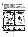
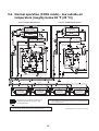
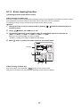
5 Combined Refrigerant Piping System Schematic Diagrams. . . . . . . . . . . . . . . . . . 32
5-1. Normal operation (COOL mode / DEFROST mode) - high outside air temperature (roughly 68 °F
(20 °C) or above) . . . . . . . . . . . . . . . . . . . . . . . . . . . . . . . . . . . . . . . . . . . . . . . . . . . . . . . . . . . . . 32
5-2. Normal operation (COOL mode) - low outside air temperature (roughly below 68 °F (20 °C)) . . 33
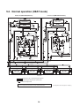
5-3. Normal operation (HEAT mode) . . . . . . . . . . . . . . . . . . . . . . . . . . . . . . . . . . . . . . . . . . . . . . . . . 34
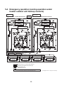
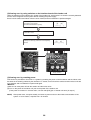
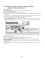
5-4. Emergency operation (cooling operation under header outdoor unit backup scenario) . . . . . . . 35
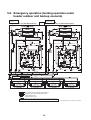
5-5. Emergency operation (heating operation under header outdoor unit backup scenario) . . . . . . . 36
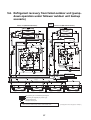
5-6. Refrigerant recovery from failed outdoor unit (pump-down operation under follower outdoor unit
backup scenario) . . . . . . . . . . . . . . . . . . . . . . . . . . . . . . . . . . . . . . . . . . . . . . . . . . . . . . . . . . . . . 37
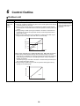
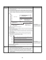
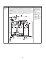
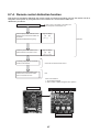
6 Control Outline. . . . . . . . . . . . . . . . . . . . . . . . . . . . . . . . . . . . . . . . . . . . . . . . . . . . . . . 38
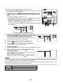
7 Applied Control and Functions . . . . . . . . . . . . . . . . . . . . . . . . . . . . . . . . . . . . . . . . . 47
7-1. Applied control for outdoor unit . . . . . . . . . . . . . . . . . . . . . . . . . . . . . . . . . . . . . . . . . . . . . . . . . . 47
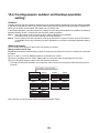
7-1-1. Outdoor fan high static pressure shift. . . . . . . . . . . . . . . . . . . . . . . . . . . . . . . . . . . . . . . 47
7-1-2. Priority operation mode setting. . . . . . . . . . . . . . . . . . . . . . . . . . . . . . . . . . . . . . . . . . . . 47
7-2. Applied control of outdoor unit . . . . . . . . . . . . . . . . . . . . . . . . . . . . . . . . . . . . . . . . . . . . . . . . . . . 49
7-2-1. Power peak-cut control (standard) . . . . . . . . . . . . . . . . . . . . . . . . . . . . . . . . . . . . . . . . . 50
7-2-2. Power peak-cut control (extended) . . . . . . . . . . . . . . . . . . . . . . . . . . . . . . . . . . . . . . . . 51
7-2-3. Snowfall fan control . . . . . . . . . . . . . . . . . . . . . . . . . . . . . . . . . . . . . . . . . . . . . . . . . . . . 52
7-2-4. External master ON/OFF control . . . . . . . . . . . . . . . . . . . . . . . . . . . . . . . . . . . . . . . . . . 52
7-2-5. Night operation (sound reduction) control . . . . . . . . . . . . . . . . . . . . . . . . . . . . . . . . . . . 53
7-2-6. Operation mode selection control. . . . . . . . . . . . . . . . . . . . . . . . . . . . . . . . . . . . . . . . . . 54
1
7-2-7. Error/operation output . . . . . . . . . . . . . . . . . . . . . . . . . . . . . . . . . . . . . . . . . . . . . . . . . . 55
7-2-8. Compressor operation output. . . . . . . . . . . . . . . . . . . . . . . . . . . . . . . . . . . . . . . . . . . . . 56
7-2-9. Operating rate output . . . . . . . . . . . . . . . . . . . . . . . . . . . . . . . . . . . . . . . . . . . . . . . . . . . 57
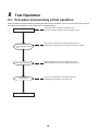
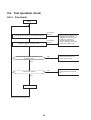
8 Test Operation . . . . . . . . . . . . . . . . . . . . . . . . . . . . . . . . . . . . . . . . . . . . . . . . . . . . . . . 58
8-1. Procedure and summary of test operation . . . . . . . . . . . . . . . . . . . . . . . . . . . . . . . . . . . . . . . . . 58
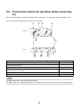
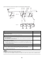
8-2. Check items before test operation (before powering-on). . . . . . . . . . . . . . . . . . . . . . . . . . . . . . . 59
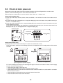
8-3. Check at main power-on . . . . . . . . . . . . . . . . . . . . . . . . . . . . . . . . . . . . . . . . . . . . . . . . . . . . . . . 63
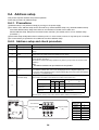
8-4. Address setup . . . . . . . . . . . . . . . . . . . . . . . . . . . . . . . . . . . . . . . . . . . . . . . . . . . . . . . . . . . . . . . 64
8-4-1. Precautions . . . . . . . . . . . . . . . . . . . . . . . . . . . . . . . . . . . . . . . . . . . . . . . . . . . . . . . . . . 64
8-4-2. Address setup and check procedure . . . . . . . . . . . . . . . . . . . . . . . . . . . . . . . . . . . . . . . 64
8-4-3. Address setup procedure . . . . . . . . . . . . . . . . . . . . . . . . . . . . . . . . . . . . . . . . . . . . . . . . 65
8-4-4. Check after address setup when central control system is connected. . . . . . . . . . . . . . 78
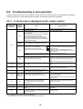
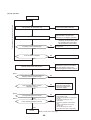
8-5. Troubleshooting in test operation . . . . . . . . . . . . . . . . . . . . . . . . . . . . . . . . . . . . . . . . . . . . . . . . 79
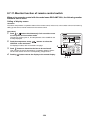
8-5-1. A check code is displayed on the remote control . . . . . . . . . . . . . . . . . . . . . . . . . . . . . . 79
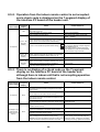
8-5-2. Operation from the indoor remote control is not accepted, and a check code is displayed
on the 7-segment display of the interface PC board of the header unit. . . . . . . . . . . . . 80
8-5-3. There is no display of a check code on the 7-segment display on the interface PC board of
the header unit, although there is indoor unit that is not accepting operation from the indoor
remote control. . . . . . . . . . . . . . . . . . . . . . . . . . . . . . . . . . . . . . . . . . . . . . . . . . . . . . . . . 80
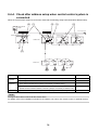
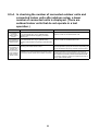
8-5-4. In checking the number of connected outdoor units and connected indoor units after address setup, a lower number of connected units is displayed. (There are outdoor/indoor
units that do not operate in a test operation.). . . . . . . . . . . . . . . . . . . . . . . . . . . . . . . . . 81
8-6. Test operation check . . . . . . . . . . . . . . . . . . . . . . . . . . . . . . . . . . . . . . . . . . . . . . . . . . . . . . . . . . 83
8-6-1. Fan check. . . . . . . . . . . . . . . . . . . . . . . . . . . . . . . . . . . . . . . . . . . . . . . . . . . . . . . . . . . . 83
8-6-2. Cooling/heating test operation check . . . . . . . . . . . . . . . . . . . . . . . . . . . . . . . . . . . . . . . 84
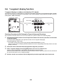
8-7. Service support function . . . . . . . . . . . . . . . . . . . . . . . . . . . . . . . . . . . . . . . . . . . . . . . . . . . . . . . 88
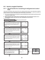
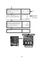
8-7-1. Check function for connecting of refrigerant and control lines . . . . . . . . . . . . . . . . . . . . 88
8-7-2. Function to start/stop (ON/OFF) indoor unit from outdoor unit . . . . . . . . . . . . . . . . . . . . 90
8-7-3. Error clearing function . . . . . . . . . . . . . . . . . . . . . . . . . . . . . . . . . . . . . . . . . . . . . . . . . . 95
8-7-4. Remote control distinction function . . . . . . . . . . . . . . . . . . . . . . . . . . . . . . . . . . . . . . . . 97
8-7-5. Pulse motor valve (PMV) forced open/close function in indoor unit . . . . . . . . . . . . . . . . 98
8-7-6. Pulse motor valve (PMV) forced open fully/close fully function in outdoor unit . . . . . . . 98
8-7-7. Solenoid valve forced open/close function in outdoor unit . . . . . . . . . . . . . . . . . . . . . . . 99
8-7-8. Fan operation check in outdoor unit . . . . . . . . . . . . . . . . . . . . . . . . . . . . . . . . . . . . . . . 100
8-7-9. Abnormal outdoor unit discrimination method by fan operating function . . . . . . . . . . . 101
8-7-10. Manual adjustment function of outside temperature (TO) sensor . . . . . . . . . . . . . . . . 102
8-7-11. Monitor function of remote control switch. . . . . . . . . . . . . . . . . . . . . . . . . . . . . . . . . . . 104
9 Troubleshooting . . . . . . . . . . . . . . . . . . . . . . . . . . . . . . . . . . . . . . . . . . . . . . . . . . . . 106
9-1. Overview . . . . . . . . . . . . . . . . . . . . . . . . . . . . . . . . . . . . . . . . . . . . . . . . . . . . . . . . . . . . . . . . . . 106
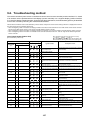
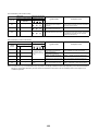
9-2. Troubleshooting method . . . . . . . . . . . . . . . . . . . . . . . . . . . . . . . . . . . . . . . . . . . . . . . . . . . . . . 107
9-3. Troubleshooting based on information displayed on remote control . . . . . . . . . . . . . . . . . . . . . 113
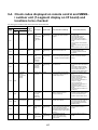
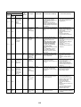
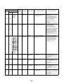
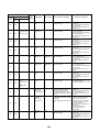
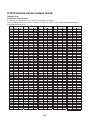
9-4. Check codes displayed on remote control and SMMS-i outdoor unit (7-segment display on I/F
board) and locations to be checked. . . . . . . . . . . . . . . . . . . . . . . . . . . . . . . . . . . . . . . . . . . . . . 117
2
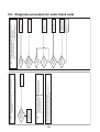
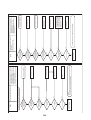
9-5. Diagnosis procedure for each check code . . . . . . . . . . . . . . . . . . . . . . . . . . . . . . . . . . . . . . . . 131
9-6. 7-segment display function . . . . . . . . . . . . . . . . . . . . . . . . . . . . . . . . . . . . . . . . . . . . . . . . . . . . 162
9-7. Oil level judgment display . . . . . . . . . . . . . . . . . . . . . . . . . . . . . . . . . . . . . . . . . . . . . . . . . . . . . 168
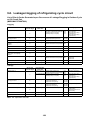
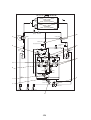
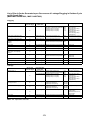
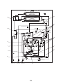
9-8. Leakage/clogging of refrigerating cycle circuit. . . . . . . . . . . . . . . . . . . . . . . . . . . . . . . . . . . . . . 169
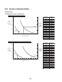
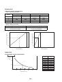
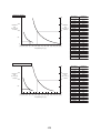
9-9. Sensor characteristics . . . . . . . . . . . . . . . . . . . . . . . . . . . . . . . . . . . . . . . . . . . . . . . . . . . . . . . . 173
9-10. Pressure sensor output check . . . . . . . . . . . . . . . . . . . . . . . . . . . . . . . . . . . . . . . . . . . . . . . . . . 176
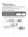
10 Backup Operation (Emergency Operation) . . . . . . . . . . . . . . . . . . . . . . . . . . . . . . . 178
10-1. Note for backup operation . . . . . . . . . . . . . . . . . . . . . . . . . . . . . . . . . . . . . . . . . . . . . . . . . . . . . 178
10-2. Compressor backup operation setting . . . . . . . . . . . . . . . . . . . . . . . . . . . . . . . . . . . . . . . . . . . . 179
10-3. Outdoor unit backup operation setting. . . . . . . . . . . . . . . . . . . . . . . . . . . . . . . . . . . . . . . . . . . . 180
10-3-1. Follower outdoor unit backup operation setting (failure of follower outdoor unit) . . . . . 180
10-3-2. Header outdoor unit backup operation setting (failure of header outdoor unit) . . . . . . 182
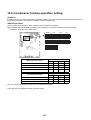
10-4. Cooling-season outdoor unit backup operation setting . . . . . . . . . . . . . . . . . . . . . . . . . . . . . . . 184
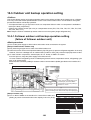
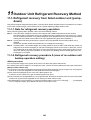
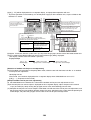
11 Outdoor Unit Refrigerant Recovery Method . . . . . . . . . . . . . . . . . . . . . . . . . . . . . . 185
11-1. Refrigerant recovery from failed outdoor unit (pump-down) . . . . . . . . . . . . . . . . . . . . . . . . . . . 185
11-1-1. Note for refrigerant recovery operation . . . . . . . . . . . . . . . . . . . . . . . . . . . . . . . . . . . . 185
11-1-2. Refrigerant recovery procedure A (case of no outdoor unit backup operation setting) 185
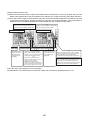
11-1-3. Refrigerant recovery procedure B (case of outdoor unit backup operation setting) . . . 188
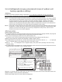
11-2. How to operate system while failed outdoor unit being repaired . . . . . . . . . . . . . . . . . . . . . . . . 190
11-3. Work procedure after repair. . . . . . . . . . . . . . . . . . . . . . . . . . . . . . . . . . . . . . . . . . . . . . . . . . . . 191
12 Replacing Compressors . . . . . . . . . . . . . . . . . . . . . . . . . . . . . . . . . . . . . . . . . . . . . . 192
12-1. Compressor replacement procedure (outline) . . . . . . . . . . . . . . . . . . . . . . . . . . . . . . . . . . . . . . 192
12-2. Replacement of compressors . . . . . . . . . . . . . . . . . . . . . . . . . . . . . . . . . . . . . . . . . . . . . . . . . . 193
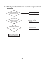
12-3. Check procedure to search cause of compressor oil shortage . . . . . . . . . . . . . . . . . . . . . . . . . 197
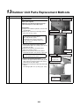
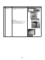
13 Outdoor Unit Parts Replacement Methods . . . . . . . . . . . . . . . . . . . . . . . . . . . . . . . 200
14 P.C. Board Exchange Procedures . . . . . . . . . . . . . . . . . . . . . . . . . . . . . . . . . . . . . . 217
14-1. Replacement of outdoor P.C.board . . . . . . . . . . . . . . . . . . . . . . . . . . . . . . . . . . . . . . . . . . . . . . 217
14-1-1. List of service P.C. boards . . . . . . . . . . . . . . . . . . . . . . . . . . . . . . . . . . . . . . . . . . . . . . 217
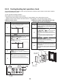
14-1-2. Configuration of inverter assembly . . . . . . . . . . . . . . . . . . . . . . . . . . . . . . . . . . . . . . . . 217
14-1-3. Interface board replacement procedure . . . . . . . . . . . . . . . . . . . . . . . . . . . . . . . . . . . . 218
14-1-4. Compressor IPDU replacement procedure . . . . . . . . . . . . . . . . . . . . . . . . . . . . . . . . . 219
14-1-5. Fan IPDU P.C. board (MCC-1610) replacement procedure. . . . . . . . . . . . . . . . . . . . . 221
14-1-6. Noise filter P.C. board (MCC-1608 A, B) replacement procedure . . . . . . . . . . . . . . . . 222
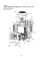
15 Exploded Diagram / Parts Price List . . . . . . . . . . . . . . . . . . . . . . . . . . . . . . . . . . . . 225
3
Generic Denomination: Air Conditioner
Definition of Qualified Installer or Qualified Service Person
The air conditioner must be installed, maintained, repaired and removed by a qualified installer or qualified service
person. When any of these jobs is to be done, ask a qualified installer or qualified service person to do them for you.
Definition of Protective Gear
When the air conditioner is to be transported, installed, maintained, repaired or removed, wear protective gloves
and ‘safety’ work clothing.
In addition to such normal protective gear, wear the protective gear described below when undertaking the special
work detailed in the table below.
Failure to wear the proper protective gear is dangerous because you will be more susceptible to injury, burns,
electric shocks and other injuries.
Work undertaken
Protective gear worn
All types of work
Protective gloves
‘Safety’ working clothing
Electrical-related work
Gloves to provide protection for electricians and from heat
Insulating shoes
Clothing to provide protection from electric shock
Work done at heights
(50 cm or more)
Helmets for use in industry
Transportation of heavy objects
Shoes with additional protective toe cap
Repair of outdoor unit
Gloves to provide protection for electricians and from heat
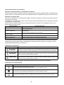
The important contents concerned to the safety are described on the product itself and on this Service Manual.
Please read this Service Manual after understanding the described items thoroughly in the following contents
(Indications/Illustrated marks), and keep them.
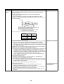
[Explanation of indications]
Indication
Explanation
DANGER
Indicates contents assumed that an imminent danger causing a death or serious injury of
the repair engineers and the third parties when an incorrect work has been executed.
WARNING
Indicates possibilities assumed that a danger causing a death or serious injury of the
repair engineers, the third parties, and the users due to troubles of the product after work
when an incorrect work has been executed.
CAUTION
Indicates contents assumed that an injury or property damage (*) may be caused on the
repair engineers, the third parties, and the users due to troubles of the product after work
when an incorrect work has been executed.
* Property damage: Enlarged damage concerned to property, furniture, and domestic animal/pet
[Explanation of illustrated marks]
Mark
Explanation
Indicates prohibited items (Forbidden items to do)
The sentences near an illustrated mark describe the concrete prohibited contents.
Indicates mandatory items (Compulsory items to do)
The sentences near an illustrated mark describe the concrete mandatory contents.
Indicates cautions (Including danger/warning)
The sentences or illustration near or in an illustrated mark describe the concrete cautious contents.
4
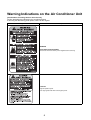
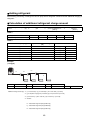
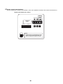
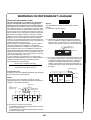
Warning Indications on the Air Conditioner Unit
[Confirmation of warning label on the main unit]
Confirm that labels are indicated on the specified positions
If removing the label during parts replace, stick it as the original.
Warning indication
Description
WARNING
ELECTRICAL SHOCK HAZARD
Disconnect all remote electric power supplies before servicing.
CAUTION
High temperature parts.
You might get burned when removing this panel.
DH79295001
5
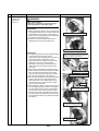
Precautions for Safety
The manufacturer shall not assume any liability for the damage caused by not observing the description of this
manual.
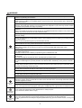
DANGER
Before carrying out the installation, maintenance, repair or removal work, be sure to set the circuit breaker for
both the indoor and outdoor units to the OFF position. Otherwise, electric shocks may result.
Before opening the intake grille of the indoor unit or service panel of the outdoor unit, set the circuit breaker to
the OFF position.
Failure to set the circuit breaker to the OFF position may result in electric shocks through contact with the interior
parts.
Only a qualified installer (*1) or qualified service person (*1) is allowed to remove the intake grille of the indoor
unit or service panel of the outdoor unit and do the work required.
Before starting to repair the outdoor unit fan or fan guard, be absolutely sure to set the circuit
breaker to the OFF position, and place a “Work in progress” sign on the circuit breaker.
Turn off
breaker.
When cleaning the filter or other parts of the indoor unit, set the circuit breaker to OFF without
fail, and place a “Work in progress” sign near the circuit breaker before proceeding with the work.
When you have noticed that some kind of trouble (such as when an error display has appeared, there is a smell
of burning, abnormal sounds are heard, the air conditioner fails to cool or heat or water is leaking) has occurred
in the air conditioner, do not touch the air conditioner yourself but set the circuit breaker to the OFF position,
and contact a qualified service person. Take steps to ensure that the power will not be turned on (by marking
“out of service” near the circuit breaker, for instance) until qualified service person arrives. Continuing to use the
air conditioner in the trouble status may cause mechanical problems to escalate or result in electric shocks or
other failure.
When you access inside of the service panel to repair electric parts, wait for about five minutes after turning off
the breaker. Do not start repairing immediately.Otherwise you may get electric shock by touching terminals of
Electric shock high-voltage capacitors. Natural discharge of the capacitor takes about five minutes.
hazard
Place a “Work in progress” sign near the circuit breaker while the installation, maintenance, repair or removal
work is being carried out.
There is a danger of electric shocks if the circuit breaker is set to ON by mistake.
Prohibition
Stay on
protection
Before operating the air conditioner after having completed the work, check that the electrical parts box cover
of the indoor unit and service panel of the outdoor unit are closed, and set the circuit breaker to the ON position.
You may receive an electric shock if the power is turned on without first conducting these checks.
If, in the course of carrying out repairs, it becomes absolutely necessary to check out the electrical parts with
the electrical parts box cover of one or more of the indoor units and the service panel of the outdoor unit
removed in order to find out exactly where the trouble lies, wear insulated heat-resistant gloves, insulated boots
and insulated work overalls, and take care to avoid touching any live parts.
You may receive an electric shock if you fail to heed this warning. Only qualified service person (*1) is allowed
to do this kind of work.
6
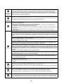
WARNING
Before starting to repair the air conditioner, read carefully through the Service Manual, and repair the air
conditioner by following its instructions.
Only qualified service person (*1) is allowed to repair the air conditioner.
Repair of the air conditioner by unqualified person may give rise to a fire, electric shocks, injury, water leaks
and/or other problems.
Do not use any refrigerant different from the one specified for complement or replacement.
Otherwise, abnormally high pressure may be generated in the refrigeration cycle, which may result in a failure
or explosion of the product or an injury to your body.
Only a qualified installer (*1) or qualified service person (*1) is allowed to carry out the electrical work of the air
conditioner.
Under no circumstances must this work be done by an unqualified individual since failure to carry out the work
properly may result in electric shocks and/or electrical leaks.
When transporting the air conditioner, wear shoes with protective toe caps, protective gloves and other
protective clothing.
When connecting the electrical wires, repairing the electrical parts or undertaking other electrical jobs, wear
gloves to provide protection for electricians and from heat, insulating shoes and clothing to provide protection
from electric shocks.
Failure to wear this protective gear may result in electric shocks.
Electrical wiring work shall be conducted according to law and regulation in the community and installation
manual. Failure to do so may result in electrocution or short circuit.
General
Only a qualified installer (*1) or qualified service person (*1) is allowed to undertake work at
heights using a stand of 19.7 in (50 cm) or more or to remove the intake grille of the indoor unit to
undertake work.
When working at heights, use a ladder which complies with the ISO 14122 standard, and follow the procedure
in the ladder’s instructions.
Also wear a helmet for use in industry as protective gear to undertake the work.
When working at heights, put a sign in place so that no-one will approach the work location, before proceeding
with the work.
Parts and other objects may fall from above, possibly injuring a person below.
When executing address setting, test run, or troubleshooting through the checking window on the electric parts
box, put on insulated gloves to provide protection from electric shock. Otherwise you may receive an electric
shock.
Do not touch the aluminum fin of the outdoor unit.
You may injure yourself if you do so. If the fin must be touched for some reason, first put on protective gloves
and safety work clothing, and then proceed.
Do not climb onto or place objects on top of the outdoor unit.
You may fall or the objects may fall off of the outdoor unit and result in injury.
When transporting the air conditioner, wear shoes with additional protective toe caps.
When transporting the air conditioner, do not take hold of the bands around the packing carton.
You may injure yourself if the bands should break.
Be sure that a heavy unit (10kg or heavier) such as a compressor is carried by two persons.
Before troubleshooting or repair work, check the earth wire is connected to the earth terminals of the main unit,
otherwise an electric shock is caused when a leak occurs.If the earth wire is not correctly connected, contact
an electric engineer for rework.
After completing the repair or relocation work, check that the ground wires are connected properly.
Check earth
wires.
Prohibition of
modification.
Be sure to connect earth wire. (Grounding work) Incomplete grounding causes an electric shock.
Do not connect ground wires to gas pipes, water pipes, and lightning rods or ground wires for telephone wires.
Do not modify the products.Do not also disassemble or modify the parts.
It may cause a fire, electric shock or injury.
When any of the electrical parts are to be replaced, ensure that the replacement parts satisfy the specifications
given in the Service Manual (or use the parts contained on the parts list in the Service Manual).
Use of any parts which do not satisfy the required specifications may give rise to electric shocks, smoking and/
Use specified or a fire.
parts.
7
If, in the course of carrying out repairs, it becomes absolutely necessary to check out the electrical parts with
the electrical parts box cover of one or more of the indoor units and the service panel of the outdoor unit
removed in order to find out exactly where the trouble lies, put a sign in place so that no-one will approach the
Do not bring a
child close to work location before proceeding with the work. Third-party individuals may enter the work site and receive
electric shocks if this warning is not heeded.
the
equipment.
Connect the cut-off lead wires with crimp contact, etc., put the closed end side upward and then apply a watercut method, otherwise a leak or production of fire is caused at the users’ side.
Insulating
measures
No fire
When performing repairs using a gas burner, replace the refrigerant with nitrogen gas because the oil that coats
the pipes may otherwise burn.
When repairing the refrigerating cycle, take the following measures.
1) Be attentive to fire around the cycle. When using a gas stove, etc., be sure to put out fire before work;
otherwise the oil mixed with refrigerant gas may catch fire.
2) Do not use a welder in the closed room. When using it without ventilation, carbon monoxide poisoning may
be caused.
3) Do not bring inflammables close to the refrigerant cycle, otherwise fire of the welder may catch the
inflammables.
The refrigerant used by this air conditioner is the R410A.
Check the used refrigerant name and use tools and materials of the parts which match with it.
For the products which use R410A refrigerant, the refrigerant name is indicated at a position on the outdoor unit
where is easy to see. To prevent miss-charging, the route of the service port is changed from one of the former
R22.
For an air conditioner which uses R410A, never use other refrigerant than R410A. For an air conditioner which
uses other refrigerant (R22, etc.), never use R410A.
If different types of refrigerant are mixed, abnormal high pressure generates in the refrigerating cycle and an
injury due to breakage may be caused.
When the air conditioner has been installed or relocated, follow the instructions in the Installation Manual and
purge the air completely so that no gases other than the refrigerant will be mixed in the refrigerating cycle.
Failure to purge the air completely may cause the air conditioner to malfunction.
Refrigerant
Do not charge refrigerant additionally. If charging refrigerant additionally when refrigerant gas leaks, the
refrigerant composition in the refrigerating cycle changes resulted in change of air conditioner characteristics or
refrigerant over the specified standard amount is charged and an abnormal high pressure is applied to the inside
of the refrigerating cycle resulted in cause of breakage or injury. Therefore if the refrigerant gas leaks, recover
the refrigerant in the air conditioner, execute vacuuming, and then newly recharge the specified amount of liquid
refrigerant.
In this time, never charge the refrigerant over the specified amount.
When recharging the refrigerant in the refrigerating cycle, do not mix the refrigerant or air other than R410A into
the specified refrigerant. If air or others is mixed with the refrigerant, abnormal high pressure generates in the
refrigerating cycle resulted in cause of injury due to breakage.
After installation work, check the refrigerant gas does not leak. If the refrigerant gas leaks in the room,
poisonous gas generates when gas touches to fire such as fan heater, stove or cocking stove though the
refrigerant gas itself is innocuous.
Never recover the refrigerant into the outdoor unit. When the equipment is moved or repaired, be sure to recover
the refrigerant with recovering device.
The refrigerant cannot be recovered in the outdoor unit; otherwise a serious accident such as breakage or injury
is caused.
Assembly/
Wiring
Insulator
check
Ventilation
After repair work, surely assemble the disassembled parts, and connect and lead the removed wires as before.
Perform the work so that the cabinet or panel does not catch the inner wires.
If incorrect assembly or incorrect wire connection was done, a disaster such as a leak or fire is caused at user’s
side.
After the work has finished, be sure to use an insulation tester set (500V Megger) to check the resistance is
1M: or more between the charge section and the non-charge metal section (Earth position).
If the resistance value is low, a disaster such as a leak or electric shock is caused at user’s side.
When the refrigerant gas leaks during work, execute ventilation.
If the refrigerant gas touches to a fire, poisonous gas generates. A case of leakage of the refrigerant and the
closed room full with gas is dangerous because a shortage of oxygen occurs. Be sure to execute ventilation.
8
When the refrigerant gas leaks, find up the leaked position and repair it surely.
If the leaked position cannot be found up and the repair work is interrupted, pump-down and tighten the service
valve, otherwise the refrigerant gas may leak into the room.
The poisonous gas generates when gas touches to fire such as fan heater, stove or cocking stove though the
refrigerant gas itself is innocuous.
When installing equipment which includes a large amount of charged refrigerant such as a multi air conditioner
in a sub-room, it is necessary that the density does not the limit even if the refrigerant leaks.
If the refrigerant leaks and exceeds the limit density, an accident of shortage of oxygen is caused.
Compulsion
Tighten the flare nut with a torque wrench in the specified manner.
Excessive tighten of the flare nut may cause a crack in the flare nut after a long period, which may result in
refrigerant leakage.
Nitrogen gas must be used for the airtight test.
The charge hose must be connected in such a way that it is not slack.
For the installation/moving/reinstallation work, follow to the Installation Manual.
If an incorrect installation is done, a trouble of the refrigerating cycle, water leak, electric shock or fire is caused.
Once the repair work has been completed, check for refrigerant leaks, and check the insulation resistance and
water drainage.
Then perform a trial run to check that the air conditioner is running properly.
After repair work has finished, check there is no trouble. If check is not executed, a fire, electric shock or injury
may be caused. For a check, turn off the power breaker.
Check after
repair
After repair work (installation of front panel and cabinet) has finished, execute a test run to check there is no
generation of smoke or abnormal sound.
If check is not executed, a fire or an electric shock is caused. Before test run, install the front panel and cabinet.
Be sure to fix the screws back which have been removed for installation or other purposes.
Check the following matters before a test run after repairing piping.
• Connect the pipes surely and there is no leak of refrigerant.
• The valve is opened.
Do not
Running the compressor under condition that the valve closes causes an abnormal high pressure resulted in
operate the damage of the parts of the compressor and etc. and moreover if there is leak of refrigerant at connecting section
unit with the
valve closed. of pipes, the air is sucked and causes further abnormal high pressure resulted in burst or injury.
Only a qualified installer (*1) or qualified service person (*1) is allowed to relocate the air conditioner. It is
dangerous for the air conditioner to be relocated by an unqualified individual since a fire, electric shocks, injury,
water leakage, noise and/or vibration may result.
Check the following items after reinstallation.
1) The earth wire is correctly connected.
2) The power cord is not caught in the product.
3) There is no inclination or unsteadiness and the installation is stable.
Check after
reinstallation If check is not executed, a fire, an electric shock or an injury is caused.
When carrying out the pump-down work shut down the compressor before disconnecting the refrigerant pipe.
Disconnecting the refrigerant pipe with the service valve left open and the compressor still operating will cause
air, etc. to be sucked in, raising the pressure inside the refrigeration cycle to an abnormally high level, and
possibly resulting in reputing, injury, etc.
When the service panel of the outdoor unit is to be opened in order for the compressor or the area around this
part to be repaired immediately after the air conditioner has been shut down, set the circuit breaker to the OFF
position, and then wait at least 10 minutes before opening the service panel.
If you fail to heed this warning, you will run the risk of burning yourself because the compressor pipes and other
parts will be very hot to the touch. In addition, before proceeding with the repair work, wear the kind of insulated
heat-resistant gloves designed to protect electricians.
Take care not to get burned by compressor pipes or other parts when checking the cooling cycle while running
the unit as they get heated while running. Be sure to put on gloves providing protection for electric shock and
heat.
Cooling check When the service panel of the outdoor unit is to be opened in order for the fan motor, reactor, inverter or the
areas around these parts to be repaired immediately after the air conditioner has been shut down, set the circuit
breaker to the OFF position, and then wait at least 10 minutes before opening the service panel.
If you fail to heed this warning, you will run the risk of burning yourself because the fan motor, reactor, inverter
heat sink and other parts will be very hot to the touch.
In addition, before proceeding with the repair work, wear the kind of insulated heat-resistant gloves designed to
protect electricians.
9
Only a qualified installer (*1) or qualified service person (*1) is allowed to install the air conditioner. If the air
conditioner is installed by an unqualified individual, a fire, electric shocks, injury, water leakage, noise and/or
vibration may result.
Before starting to install the air conditioner, read carefully through the Installation Manual, and follow its
instructions to install the air conditioner.
Be sure to use the company-specified products for the separately purchased parts. Use of non-specified
products may result in fire, electric shock, water leakage or other failure. Have the installation performed by a
qualified installer.
Do not supply power from the power terminal block equipped on the outdoor unit to another outdoor unit.
Capacity overflow may occur on the terminal block and may result in fire.
Do not install the air conditioner in a location that may be subject to a risk of expire to a combustible gas.
If a combustible gas leaks and becomes concentrated around the unit, a fire may occur.
Installation
Install the indoor unit at least 2.5 m above the floor level since otherwise the users may injure themselves or
receive electric shocks if they poke their fingers or other objects into the indoor unit while the air conditioner is
running.
Install a circuit breaker that meets the specifications in the installation manual and the stipulations in the local
regulations and laws.
Install the circuit breaker where it can be easily accessed by the qualified service person (*1).
If you install the unit in a small room, take appropriate measures to prevent the refrigerant from exceeding the
limit concentration even if it leaks. Consult the dealer from whom you purchased the air conditioner when you
implement the measures. Accumulation of highly concentrated refrigerant may cause an oxygen deficiency
accident.
Do not place any combustion appliance in a place where it is directly exposed to the wind of air conditioner,
otherwise it may cause imperfect combustion.
Explanations given to user
• If you have discovered that the fan grille is damaged, do not approach the outdoor unit but set the circuit breaker
to the OFF position, and contact a qualified service person to have the repairs done.
Do not set the circuit breaker to the ON position until the repairs are completed.
Relocation
• Only a qualified installer (*1) or qualified service person (*1) is allowed to relocate the air conditioner.
It is dangerous for the air conditioner to be relocated by an unqualified individual since a fire, electric shocks,
injury, water leakage, noise and/or vibration may result.
• When carrying out the pump-down work shut down the compressor before disconnecting the refrigerant pipe.
Disconnecting the refrigerant pipe with the service valve left open and the compressor still operating will cause
air, etc. to be sucked in, raising the pressure inside the refrigeration cycle to an abnormally high level, and
possibly resulting in reputing, injury, etc.
(*1) Refer to the “Definition of Qualified Installer or Qualified Service Person.”
10
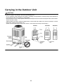
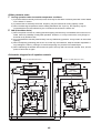
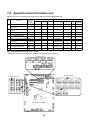
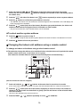
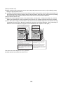
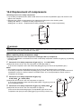
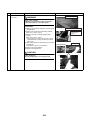
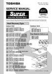
Carrying in the Outdoor Unit
CAUTION
Handle the outdoor unit carefully, observing the following items.
• To use a forklift or other machinery for loading / unloading in transportation, insert the prongs of the forklift into
the rectangular holes for handling as shown below.
• To lift up the unit, insert a rope capable of bearing the weight of the unit into the rectangular holes shown below.
Tie the unit from 4 sides.
(Apply padding in positions where the rope comes in contact with the outdoor unit so that no damage is caused
to the outer surface of the outdoor unit.)
(There are reinforcing plates on the side surfaces, so the rope cannot be passed through.)
11
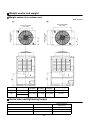
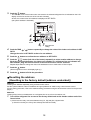
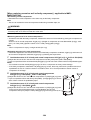
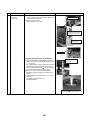
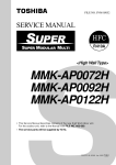
Weight centre and weight
◆ Weight centre of an outdoor unit
Model type
(A)
(B)
MAP072
MAP096
MAP114
Unit: in (mm)
X
(in (mm))
Y
(in (mm))
Z
(in (mm))
Weight (lb (kg))
19.7” (500)
15.4” (390)
25.4” (645)
546 (247)
23.8” (605)
13.8” (350)
27.6” (700)
742 (336)
Screw size and tightening torque
Power supply terminal
Ground screw
Control wire terminal
Screw size
Tightening torque
(ft•lbs (N•m))
M8
4.1 to 4.8 (5.5 to 6.6)
M8
4.1 to 4.8 (5.5 to 6.6)
M3.5
0.6 to 0.7 (0.80 to 0.96)
12
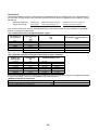
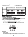
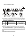
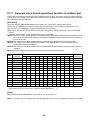
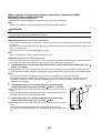
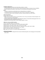
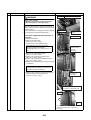
Adding refrigerant
After finishing vacuuming, exchange the vacuum pump with a refrigerant canister and start additional charging of
refrigerant.
Calculation of additional refrigerant charge amount
Additional refrigerant charge
amount
=
(lb)
Actual length of liquid
pipe
×
Additional refrigerant charge
amount per liquid pipe 1ft
[Table 3]
Adjustment amount of
refrigerant
[Table 4]
+
Table 3
Liquid pipe outer dia.
Ø1/4
Ø3/8
Ø1/2
Ø5/8
Ø3/4
Additional refrigerant amount / 1 ft (lb)
0.017
0.037
0.071
0.108
0.168
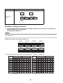
Table 4
Adjustment amount of refrigerant
(lb)
Outdoor unit capacity type
Combined outdoor units
072 type
3.31
072 type
–
096 type
13.23
096 type
–
114 type
15.43
114 type
–
144 type
0.00
072 type
072 type
168 type
16.53
096 type
072 type
192 type
27.56
096 type
096 type
228 type
27.56
114 type
114 type
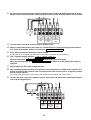
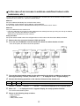
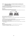
Example:
(114 type)
L3
L2
L1
a
b
c
d
L1
Ø1/2: 30 ft
L2
Ø1/2: 15 ft
L3
Ø3/8: 10 ft
a
Ø1/4: 10 ft
b
Ø3/8: 15 ft
c
Ø1/4: 10 ft
Additional charge amount (lb)
=
(Lx × 0.017 lb/ft) + (Ly × 0.037 lb/ft) + (Lz X 0.071 lb/ft) + (15.43 lb)
=
((a+c+d)×0.017 lb)+((L3+b)× 0.037 lb)+((L1+L2)× 0.017 lb+(15.43 lb)
=
(30 × 0.017 lb) + (25 × 0.037 lb) + (45 × 0.071 lb) + (15.43 lb)
=
20.06 lb
Lx : Actual total length of liquid pipe Ø1/4 (ft)
Ly : Actual total length of liquid pipe Ø3/8 (ft)
Lz : Actual total length of liquid pipe Ø1/2 (ft)
13
d
Ø1/4: 10 ft
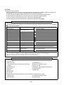
New Refrigerant (R410A)
This air conditioner adopts a new HFC type refrigerant (R410A) which does not deplete the ozone layer.
1. Safety Caution Concerned to New Refrigerant
The pressure of R410A is high 1.6 times of that of the former refrigerant (R22). Accompanied with change of
refrigerant, the refrigerating oil has been also changed. Therefore, be sure that water, dust, the former refrigerant
or the former refrigerating oil is not mixed into the refrigerating cycle of the air conditioner with new refrigerant
during installation work or service work. If an incorrect work or incorrect service is performed, there is a possibility
to cause a serious accident. Use the tools and materials exclusive to R410A to purpose a safe work.
2. Cautions on Installation/Service
(1) Do not mix the other refrigerant or refrigerating oil.
For the tools exclusive to R410A, shapes of all the joints including the service port differ from those of the former
refrigerant in order to prevent mixture of them.
(2) As the use pressure of the new refrigerant is high, use material thickness of the pipe and tools which are
specified for R410A.
(3) In the installation time, use clean pipe materials and work with great attention so that water and others do not
mix in because pipes are affected by impurities such as water, oxide scales, oil, etc. Use the clean pipes.
Be sure to brazing with flowing nitrogen gas. (Never use gas other than nitrogen gas.)
(4) For the earth protection, use a vacuum pump for air purge.
(5) R410A refrigerant is azeotropic mixture type refrigerant. Therefore use liquid type to charge the refrigerant.
(If using gas for charging, composition of the refrigerant changes and then characteristics of the air conditioner
change.)
3. Pipe Materials
For the refrigerant pipes, copper pipe and joints are mainly used. It is necessary to select the most appropriate
pipes to conform to the standard. Use clean material in which impurities adhere inside of pipe or joint to a minimum.
(1) Copper pipe
<Piping>
The pipe thickness, flare finishing size, flare nut and others differ according to a refrigerant type.
When using a long copper pipe for R410A, it is recommended to select “Copper or copper-base pipe without
seam” and one with bonded oil amount 40mg/10m or less. Also do not use crushed, deformed, discolored
(especially inside) pipes. (Impurities cause clogging of expansion valves and capillary tubes.)
<Flare nut>
Use the flare nuts which are attached to the air conditioner unit.
(2) Joint
The flare joint and socket joint are used for joints of the copper pipe. The joints are rarely used for installation
of the air conditioner. However clear impurities when using them.
14
4. Tools
(1) Required Tools for R410A
Mixing of different types of oil may cause a trouble such as generation of sludge, clogging of capillary, etc.
Accordingly, the tools to be used are classified into the following three types.
1) Tools exclusive for R410A (Those which cannot be used for conventional refrigerant (R22))
2) Tools exclusive for R410A, but can be also used for conventional refrigerant (R22)
3) Tools commonly used for R410A and for conventional refrigerant (R22)
The table below shows the tools exclusive for R410A and their interchangeability.
Tools exclusive for R410A (The following tools for R410A are required.)
Explanation of symbols
: Newly prepared (It is necessary to use it exclusively with R410A, separately from those for R22 or R407C.)
: Former tool is available.
Used tools
Usage
Gauge manifold
Proper use of tools/parts
Vacuuming, charging refrigerant
and operation check
Charging hose
Exclusive to R410A
Exclusive to R410A
Charging cylinder
Charging refrigerant
Gas leak detector
Checking gas leak
Unusable (Use the Refrigerant charging balance.)
Vacuum pump
Vacuum drying
Vacuum pump with counterflow
Vacuum drying
R22 (Existing article)
Flare tool
Flare processing of pipes
Usable by adjusting size
Bender
Bending processing of pipes
R22 (Existing article)
Refrigerant recovery device
Recovering refrigerant
Exclusive to R410A
Torque wrench
Tightening flare nut
Exclusive to Ø1/4” (6.4 mm) to Ø5/8” (15.9 mm)
Pipe cutter
Cutting pipes
R22 (Existing article)
Refrigerant canister
Charging refrigerant
Exclusive to R410A
Enter the refrigerate name for identification
Welding machine/Nitrogen gas
cylinder
Welding of pipes
R22 (Existing article)
Refrigerant charging balance
Charging refrigerant
R22 (Existing article)
Exclusive to R410A
Usable if a counter-flow preventive adapter is attached
(Note 1) When flaring is carried out for R410A using the conventional flare tools, adjustment of projection
margin is necessary. For this adjustment, a copper pipe gauge, etc. are necessary.
(Note 2) Charging cylinder for R410A is being currently developed.
General tools (Conventional tools can be used.)
In addition to the above exclusive tools, the following equipments which serve also for R22 are necessary as
the general tools.
(7) Screwdriver (+, –)
(1) Vacuum pump
(8) Spanner or Monkey wrench
Use vacuum pump by attaching vacuum pump
adapter.
(9) Hole core drill
(2) Torque wrench
(10)Hexagon wrench (Opposite side 4mm)
(3) Pipe cutter
(11)Tape measure
(4) Reamer
(12)Metal saw
(5) Pipe bender
(6) Level vial
Also prepare the following equipments for other installation method and run check.
(1) Clamp meter
(3) Insulation resistance tester
(2) Thermometer
(4) Electroscope
15
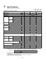
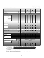
1
Specifications
(System with Non ducted indoor units)
208/230 V / 3 Ph / 60 Hz
(Heat pump model)
TOSHIBA Carrier VRF Air conditioner
Outdoor unit model name
MMY-
MAP0724HT9UL MAP0964HT9UL MAP1144HT9UL
Cooling Capacity
(*1)
kBtu/h
72
96
114
Heating Capacity
(*1)
kBtu/h
81
108
128
Power supply
Starting Current
Dimension
230 V (208/230 V) 3 phase 60 Hz
A
Soft Start
Height
In
72.9
72.9
72.9
Width
In
39.0
47.6
47.6
Depth
In
30.7
30.7
30.7
Height
In
76.3
76.3
76.3
Width
In
41.8
50.5
50.5
Depth
In
32.6
32.6
32.6
Unit
lb
546
742
742
Packed unit
lb
579
779
779
Unit
Packing
Total Weight
(*2)
Appearance (Color)
Silky shade (Munsell 1Y8.5/0.5)
Compressor
Type
Hermetic twin rotary compressor
Fan unit
Fan
Motor output
kW
2.3 x 2
Motor output
Air volume
W
1,000
1,000
1,000
5,800
6,600
7,060
Finned tube
Refrigerant R410A (Charged refrigerant amount(lb))
(*3)
High-pressure switch
psi
Protective devices
Refrigerant
piping
2.5 x 3
cfm
Heat exchanger
Electrical
specifications
2.1 x 3
Propeller fan
Unit
Connecting
port dia
(*4)
A
36
50
52
MOCP
(*5)
A
40
60
60
Gas side (main pipe)
In
7/8”
7/8”
1-1/8”
Liquid side (main pipe)
In
1/2”
1/2”
1/2”
In
3/8”
3/8”
3/8”
(Up to 3280 ft)
Shielded wire
(Up to 6560 ft)
Shielded wire
Cooling
Heating
Max external static pressure
FDB
The standard pipe
Cooling/Heating
dB(A)
AWG16 x 2 cores
AWG14 x 2 cores
23 to 109
FWB
In WG
Max. No. of connected indoor units
(*1) Rated conditions
25.4
ON: 540
MCA
Balance pipe
Sound pressure level
25.4
OFF: 420
High-pressure switch / High-pressure sensor /
Low-pressure sensor / Fusible plug / PC board fuse /
Inverter overload protector
System interconnection wiring
Operation temperature range
25.4
5 to 60
0.20
0.20
0.20
12
16
19
56/57
60/62
62/63
Cooling : Indoor 80 degF Dry Bulb / 67 degF Wet Bulb, Outdoor 95 degF Dry Bulb.
Heating : Indoor 70 degF Dry Bulb, Outdoor 47 degF Dry Bulb / 43 degF WetBulb.
P072type, P096type
Equivalent piping length : 50 ft, Hight difference : 0 ft
P114type
Equivalent piping length : 75 ft, Hight difference : 0 ft
(*2) The source voltage must not fluctuate more than ±10 %
(*3) The amount dose not consider extra piping length. Refrigerant must be added on site in accordance with the actual
piping length.
(*4) Select wire size base on the larger value of MCA.
MCA : Minimum Circuit Amps (minimum circuit Amps required for power supply design.)
(*5) MOCP : Maximum Overcurrent Protection (Amps)
16
208/230 V / 3 Ph / 60 Hz
(Heat pump model)
TOSHIBA Carrier VRF Air conditioner
Outdoor unit set model name
MMY-
Outdoor unit model name
MMY-MAP
AP1444HT9UL
AP1684HT9UL
AP1924HT9UL
AP2284HT9UL
0724HT9UL 0724HT9UL 0964HT9UL 0724HT9UL 0964HT9UL 0964HT9UL 1144HT9UL 1144HT9UL
Cooling Capacity
(*1)
kBtu/h
144
168
192
220
Heating Capacity
(*1)
kBtu/h
162
189
212
247
Power supply
Starting Current
Dimension
Unit
Packing
Total Weight
(*2)
230 V (208/230 V) 3 phase 60 Hz
A
Soft Start
Height
In
72.9
72.9
72.9
72.9
72.9
72.9
72.9
72.9
Width
In
39.0
39.0
47.6
39.0
47.6
47.6
47.6
47.6
Depth
In
30.7
30.7
30.7
30.7
30.7
30.7
30.7
30.7
Height
In
76.3
76.3
76.3
76.3
76.3
76.3
76.3
76.3
Width
In
41.8
41.8
50.5
41.8
50.5
50.5
50.5
50.5
Depth
In
32.6
32.6
32.6
32.6
32.6
32.6
32.6
32.6
Unit
lb
546
546
742
742
742
742
742
742
Packed unit
lb
579
579
779
779
779
779
779
779
Appearance (Color)
Silky shade (Munsell 1Y8.5/0.5)
Compressor
Hermetic twin rotary compressor
Type
Motor output
Fan unit
kW
2.3 x 2 2.3 x 2 2.1 x 3 2.3 x 2 2.1 x 3 2.1 x 3 2.5 x 3 2.5 x 3
Fan
Propeller fan
Motor output
Air volume
W
1,000
1,000
1,000
1,000
1,000
1,000
1,000
1,000
cfm
5,800
5,800
6,600
5,800
6,600
6,600
7,060
7,060
25.4
25.4
25.4
Heat exchanger
Finned tube
Refrigerant R410A(Charged refrigerant amount(lb))
(*3)
High-pressure switch
psi
Protective devices
MCA
(*4)
MOCP
(*5)
Refrigerant
piping
Gas side (main pipe)
Connecting
Liquid side (main pipe)
port dia
Balance pipe
System interconnection wiring
25.4
25.4
25.4
OFF: 420
ON: 540
A
36
A
40
36
50
40
60
36
50
40
60
60
60
1-1/8"
1-3/8"
In
5/8"
5/8"
5/8"
3/4"
In
3/8”
3/8”
3/8”
3/8”
(Up to 3280 ft)
Shielded wire
AWG16 x 2 cores
(Up to 6560 ft)
Shielded wire
AWG14 x 2 cores
FDB
23 to 109
5 to 60
In WG
0.20
Max. No. of connected indoor units
The standard pipe
60
52
1-1/8"
FWB
(*1) Rated conditions
52
1-1/8"
Heating
Cooling/Heating
50
In
Cooling
Max external static pressure
Sound pressure level
25.4
High-pressure switch / High-pressure sensor / Low-pressure sensor /
Fusible plug / PC board fuse / Inverter overload protector
Electrical
specifications Unit
Operation temperature
range
25.4
dB(A)
0.20
0.20
0.20
0.20
0.20
0.20
28
32
38
59/60
61.5/63.5
63/65
65/66
Cooling : Indoor 80 degF Dry Bulb / 67 degF Wet Bulb, Outdoor 95 degF Dry Bulb.
Heating : Indoor 70 degF Dry Bulb, Outdoor 47 degF Dry Bulb / 43 degC WetBulb.
P144type - P228type Equivalent piping length : 100 ft, Hight difference : 0 ft
(*2) The source voltage must not fluctuate more than ±10 %
(*3) The amount dose not consider extra piping length. Refrigerant must be added on site in accordance with the actual
piping length.
(*4) Select wire size base on the larger value of MCA.
MCA : Minimum Circuit Amps (minimum circuit Amps required for power supply design.)
(*5) MOCP : Maximum Overcurrent Protection (Amps)
17
0.20
24
CN31
CN41
U
U
U
U
MCC-1608B
BLK CN13
WHI CN12
RED CN11
F03
F02
F01
MCC-1608A
BLK
WHI
RED
BLK
WHI
RED
TB3 1 2 3
RED WHI BLK
RED WHI BLK
CN32
RED WHI BLK
CN33
CN43
CN42
CN-R
CN22 (RED)
CN50
(BLK)
RED
GRY
HEATER1
HEATER2
4
4WV1
A.HEATER
CN01
(BLU)
F02
CN400 (WHI)
F01
CN530 (BLK)
3
1
CN335(GRY)
3
1
CN331(WHI)
3
1
CN332(BLU)
3
1
CN334(RED)
3
1
CN317 (BLU)
2
1
(WHI)
1
2 CN03
6
L-CM1
7
5
5
SW16
SW12
SW13
1 2 34
3~
L-CM2
RED WHI BLK
V W
+
+ -
U
+
F02
4
ON
OFF
5
P>
63H2
CN251 (BLK)
CM2
-
(RED)
CN851
6
2
4
U V W
FM
-
CN511
CN510
RED:RED
WHI:WHITE
YEL:YELLOW
BLU:BLUE
BLK:BLACK
GRY:GRAY
PNK:PINK
ORN:ORANGE
BRN:BROWN
GRN:GREEN
Color indication
TK5
TK4
TK2
TK1
TL1
TE1
TO
TS1
TD2
TD1
V
W
U
Compressor terminal
L-FM
t°
t°
t°
t°
t°
t°
t°
t°
t°
t°
P.C.boards can be installed up to three pieces.
3~
MS
5
CN504 (BLU)
++ - -
+
1
CN535
(RED) 2
1
CN534
(YEL) 3
1
CN532
(GRN) 3
1
CN531
(BLK) 3
1
CN523
(WHI) 2
1
CN520
(GRN) 2
1
CN507
(YEL) 2
1
CN505
(WHI) 2
1
CN503
(PNK) 3
1
CN502
(WHI) 3
CN600(BLU)
RED WHI BLK
F500
(RED)
CN505
(WHI)
CN500
MCC-1610
SV3E
3
* 1Optional
SV3D
1
D600 D601 D602 D603 D604
SW01 SW02 SW03
2 34
CN500
(WHI)
3
3
1 34
CN501
(RED)
PS
PD
SW04 SW05 SW15
CN514
(GRN)
CN30 CN32
CN31
CN513
(BLU)
SV3A
3
CN852 (WHI)
F03
-
5
SV3B
2
1 2 34
SW14
1 2 34
SW10
CN512
(BLU)
ON
OFF
SV3C
1
RED WHI BLK
3
MCC-1595
SV2
1
SW09
1 23 4
CN800
SWRT
ON
OFF
ON
OFF
(Service)
1 2 34
SW17
1 2 34
ON
OFF
ON
OFF
SW07
1 2 34
CN511
(GRN)
MS
SV51
2
12
SW30
1 23 4
ON
OFF
1
SW11
1 2 34
ON
OFF
CN510
(WHI)
3~
P>
63H1
CN251(BLK)
CN852 (WHI)
CM1
-
-
F03 (RED)
CN851
SV42
5
SW06
CN509
(BLK)
1 2 34
ON
OFF
ON
OFF
ON
OFF
CN508
(RED)
Connector for optional P.C.BOARD *1
MS
RED WHI BLK
V W
+
+ -
U
+
F02
6
3
SV41
1
CN300
(WHI)
1 2 3 4
RED WHI BLK
MCC-1595
CN301
(WHI)
1 2 3 4
5
M
5
M
CN01
MCC-1606
CN04
TB2 U1 U2 U3 U4 U5 U6
CN23
PMV1
CN05
TB1 L1 L2 L3
CN24
PMV2
CN314 (WHI)
TO INDOOR TO CENTRAL TO OUTDOOR
UNIT CONTROLLER UNIT
CN04
CN312 (BLU)
CN201
CN01
3PHASE 60Hz 208/230V
CN322 (WHI)
POWER SUPPLY
CN02
CN202
CN311 (WHI)
CN05
CN321(WHI)
CN02
CN201
CN705
CN03
CN203
CN03
CN203
CN202
CN704
18
CN703
MCC-1595
(CM2)
MCC-1606
TB1
L2
TB2
U1 U2 U3 U4 U5 U6
L1
L3
TB3
1 2
3
MCC1608B
MCC1608A
BACK
*Noise filter P.C. boards are installedon a back of
terminal block. (TB1,TB2)
MCC-1595
(CM1)
MCC-1610
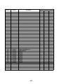
Parts layout
P.C.board
Terminal block
Terminal
Connector
FRONT
Pipe temp.sensor(discharge)
Heat exchange temp.sensor
Oil temp.sensor
Liquid temp.sensor
Air temp.sensor
Pipe temp.sensoer
Terminal block(power supply)
Terminal block(control wiring)
Terminal block(relay wiring)
Dip switch
Rotary switch
Push button switch
2-way valve coil
Accumulator case heater
Reactor for compressor
Reactor for fan
Pressure sensor(High)
Pressure sensor(Low)
Pulse motor valve(main)
Field wiring
Protective earth
SW01,SW02,SW03
SW04,SW05,SW15
SW06,SW07,SW09,SW10
SW 11,SW12,SW13,SW14
SW16,SW17,SW30
TD1,TD2
TE1
TK1,TK2,TK4,TK5
TL1
TO
TS1
TB1
TB2
TB3
A.HE ATER
L-CM1,L-CM2
L-FM
PD
PS
PMV1,PMV2
SV2,SV3A,SV3B,SV3C
SV3D,SV3E,SV41,SV42
SV51
Compressor case heater
Parts name
4-way valve coil
High pressure switch
Compressor
Relay connector
Connector
Fuse(Compressor)
30 A 250V~
Fuse(Interface)
T6.3 A 250V~
Fuse(Noise filter)
T6.3 A 250V~
Fuse(Fan)
15 A 250V~
Fan motor
Symbol
4WV1
63H1,63H2
CM1,CM2
CN-R
CN**
(MCC-1595)
F02,F03
(MCC-1606)
F01,F02
(MCC-1608A)
F01,F02,F03
(MCC-1610)
F500
FM
HE ATER1,HE ATER2
Parts name
Inverter P.C.Board(Compressor)
Interface Control
P.C.Board
Noise filter P.C.Board A
Noise filter P.C.Board B
Inverter P.C.Board(Fan)
P.C.Board
Symbol
MCC-1595
MCC-1606
MCC-1608A
MCC-1608B
MCC-1610
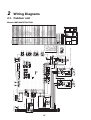
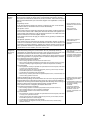
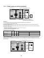
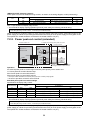
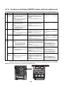
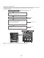
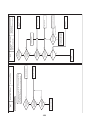
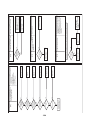
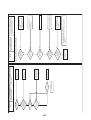
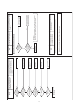
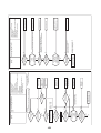
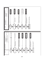
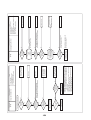
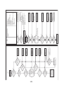
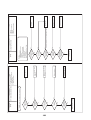
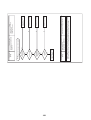
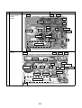
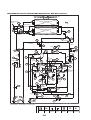
2
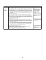
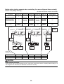
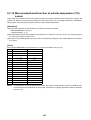
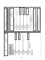
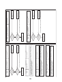
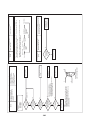
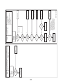
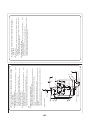
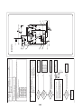
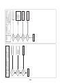
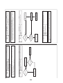
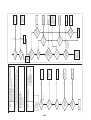
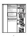
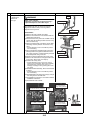
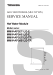
Wiring Diagrams
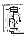
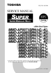
2-1. Outdoor unit
Models: MMY-MAP0724HT9UL
CN32
CN31
CN41
U
U
U
U
TB5
L-CM3 L-CM2 L-CM1
TB4 1 2 3
BLK CN13
WHI CN12
RED WHI BLK
MCC-1608B
RED CN11
F03
F02
F01
BLK
WHI
RED
BLK
WHI
RED
TB3 1 2 3
BLK BLK BLK
BLK BLK BLK
CN33
CN43
CN42
MCC-1608A
CN22 (RED)
CN50
(BLK)
RED WHI BLK
RED
GRY
HEATER1
HEATER2
HEATER3
4
CN01
(BLU)
CN03
(WHI)
-
-
CN851
(RED)
5
6
6
3
+
F02
V W
MS
3~
RED WHI BLK
U
(RED)
CN851
5
5
P>
63H2
CN251(BLK)
CM2
-
-
7
SV42
5
SW16
2
12
SW30
1 2 34
ON
OFF
1
SW11
1 2 34
3~
MS
RED WHI BLK
V W
+
+ -
U
+
F02
4
ON
OFF
ON
OFF
3
2 34
CN500
(WHI)
1 34
CN501
(RED)
6
5
5
2
SV3D
1
4
U V W
MS
RED WHI BLK
1
CN535
(RED) 2
1
CN534
(YEL) 3
1
CN532
(GRN) 3
1
CN533
(RED) 3
CN531
(BLK) 3
5
FM
-
1
1
CN521
(RED) 2
1
CN523
(WHI) 2
1
CN520
(GRN) 2
1
CN507
(YEL) 2
1
CN505
(WHI) 2
1
CN504
(BLU) 3
CN511
CN510
L-FM
t°
t°
t°
t°
t°
t°
t°
t°
t°
t°
t°
t°
t°
RED:RED
WHI:WHITE
YEL:YELLOW
BLU:BLUE
BLK:BLACK
GRY:GRAY
PNK:PINK
ORN:ORANGE
BRN:BROWN
GRN:GREEN
Color indication
V
W
U
Compressor terminal
TK5
TK4
TK3
TK2
TK1
TL1
TE2
TE1
TO
TS1
TD3
TD2
TD1
P.C.boards can be installed up to three pieces.
3~
CN502
(WHI) 3
1
1
CN503
(PNK) 3
CN504 (BLU)
++ - -
+
* 1Optional
(RED)
CN505
F500
(WHI)
CN500
3
SV3F
1
MCC-1610
SV3E
3
D600 D601 D602 D603 D604
SW01 SW02 SW03
P>
63H3
CN251(BLK)
CN852 (WHI)
3
3
CN600(BLU)
PS
PD
SW04 SW05 SW15
CN514
(GRN)
CN30 CN32
CN31
CN513
(BLU)
SV3A
(RED)
CN851
CM3
-
-
5
SV3B
2
1 2 34
SW14
1 2 34
F03
SV3C
1
RED WHI BLK
MCC-1595
3
(Service)
1 2 34
SW13
1 2 34
CN800
SWRT
ON
OFF
ON
OFF
SV2
1
1 23 4
SW17
1 23 4
SW12
1 2 34
ON
OFF
ON
OFF
ON
OFF
SW09
SW07
SW06
SW10
CN511
CN512
(BLU)
(GRN)
CN510
(WHI)
P.C.board *1
CN509
(BLK)
Connector for optional
1 234
ON
OFF
ON
OFF
ON
OFF
CN508
(RED)
CN852 (WHI)
F03
6
3
SV41
1
CN300
(WHI)
+ -
+
5
1 2 3 4
M
PMV1
RED WHI BLK
SV43
1
MCC-1595
3
SV61
1
CN301
(WHI)
1 2 3 4
5
3~
P>
63H1
CN251(BLK)
CN852 (WHI)
F03
F02
CN400 (WHI)
F01
CN530 (BLK)
3
1
CN335 (GRY)
3
1
CN331 (WHI)
3
1
CN332 (BLU)
3
1
CN333 (BLK)
3
1
CN334 (RED)
3
1
CN303
(RED)
1 2 3 4
5
MS
RED WHI BLK
V W
+
+ -
U
+
F02
2
1
1
2
CN317(BLU)
CM1
4WV1
A.HEATER
MCC-1595
CN-R
CN04
BLK BLK BLK
CN23
CN05
MCC-1606
CN315 (WHI)
TB2 U1 U2 U3 U4 U5 U6
CN24
CN01
CN201
M
CN04
CN312 (BLU)
TB1 L1 L2 L3
CN02
CN202
CN314 (WHI)
PMV2
CN04
M
CN322 (WHI)
PMV4
CN05
CN311 (WHI)
CN05
CN323 (WHI)
TO INDOOR TO CENTRAL TO OUTDOOR
UNIT CONTROLLER UNIT
CN03
CN203
CN01
CN313 (RED)
CN01
CN201
CN02
CN202
CN705
CN321(WHI)
CN02
CN201
CN03
CN203
CN03
CN203
CN202
CN704
19
CN703
POWER SUPPLY
3PHASE 60Hz 208/230V
3
MCC-1595
(CM2)
MCC-1610
MCC-1595
(CM3)
MCC-1606
L3
TB1
L2
TB2
U1 U2 U3 U4 U5 U6
L1
TB3
1 2 3
MCC1608B
MCC1608A
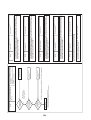
BACK
*Noise filter P.C. boards are installedon a back of
terminal block. (TB1,TB2)
MCC-1595
(CM1)
TB5
TB4
1 2
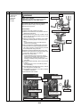
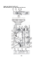
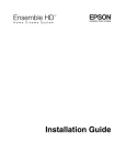
Parts layout
P.C.board
Terminal block
Terminal
Connector
FRONT
Pipe temp.sensor(discharge)
Heat exchange temp.sensor
Oil temp.sensor
Liquid temp.sensor
Air temp.sensor
Pipe temp.sensoer(Suction)
Terminal block(power supply)
Terminal block(control wiring)
Terminal block(relay wiring)
Terminal block(relay wiring)
Terminal block(relay wiring)
Dip switch
Rotary switch
Push button switch
2-way valve coil
Accumulator case heater
Reactor for compressor
Reactor for fan
Pressure sensor(High)
Pressure sensor(Low)
Pulse motor valve(main)
Pulse motor valve(sub)
Compressor case heater
Parts name
4-way valve coil
High pressure switch
Compressor
Relay connector
Connector
Fuse(Compressor)
30 A 250V~
Fuse(Interface)
T6.3 A 250V ~
Fuse(Noise filter)
T6.3 A 250V ~
Fuse(Fan)
15 A 250V ~
Fan motor
Parts name
Inverter P.C.Board (Compressor)
Interface Control P.C.Board
Noise filter P.C.Board A
Noise filter P.C.Board B
Inverter P.C.Board(Fan)
Field wiring
Protective earth
SW01,SW02,SW03
SW04,SW05,SW15
SW06,SW07,SW09,SW10
SW 11,SW12,SW13,SW14
SW16,SW17,SW30
TD1,TD2,TD3
TE1,TE2
TK1,TK2,TK3,TK4,TK5
TL1
TO
TS1
TB1
TB2
TB3
TB4
TB5
Symbol
4WV1
63H1,63H2,63H3
CM1,CM2,CM3
CN-R
CN**
(MCC-1595)
F02,F03
(MCC-1606)
F01,F02
(MCC-1608A)
F01,F02,F03
(MCC-1610)
F500
FM
HE ATER1,HE ATER2
HE ATER3
A.HE ATER
L-CM1,L-CM2,L-CM3
L-FM
PD
PS
PMV1,PMV2
PMV4
SV2,SV3A,SV3B,SV3C
SV3D,SV3E,SV3 F,SV41
SV42,SV43,SV61
P.C.Board
Symbol
MCC-1595
MCC-1606
MCC-1608 A
MCC-1608B
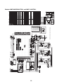
MCC-1610
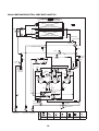
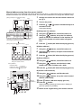
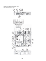
Models: MMY-MAP0964HT9UL and MAP1144HT9UL
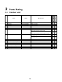
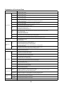
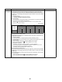
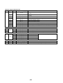
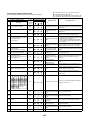
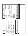
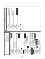
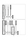
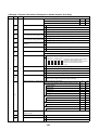
3
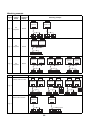
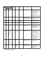
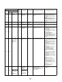
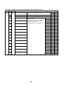
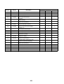
Parts Rating
Specification
1
Compressor
DA421A3FB-28M
Output: 2.3 kW×2
1
Compressor
DA421A3FB-28M
Output: 2.1 kW×3
1
Compressor
DA421A3FB-28M
Output: 2.1 kW×3
MMY-MAP1144
Model
MMY-MAP0964
Name
MMY-MAP0724
3-1. Outdoor unit
O
O
O
2
4-way valve coil
STF
AC208-230 V 60 Hz
O
O
O
3
Pulse motor valve coil
HAM-BD28TF-2
DC12 V
O
O
O
2-way valve coil
VPV
AC208-230 V 60 Hz
SV2,SV3A,SV3B,SV3C,SV3D,SV3E
O
O
O
O
O
4
AC208-230 V 60 Hz
SV2,SV3A,SV3B,SV3C,SV3D,SV3E,SV3F,SV6
2-way valve coil
FQ-D640
AC208-230 V 60 Hz
SV41,SV42,SV5
5
O
AC208-230 V 60 Hz
SV41,SV42,SV43
6
High-pressure SW
OFF:3.73 MPa ON:2.9 MPa
O
O
O
7
Pressure sensor (For high pressure) NSK-BC038F-U220
ACB-4UB
0.5~4.3 V / 0~3.73 MPa
O
O
O
8
Pressure sensor (For low pressure)
NSK-BC010F-U220
0.5~3.5 V / 0~0.98 MPa
O
O
O
9
Fan motor
STF-340A1000-1
DC280 V / 1 kW
O
O
O
AC240 V / 29 W
O
O
O
10 Case heater (For comp.)
11 Case heater (For accum.)
AC240 V / 55 W
O
O
O
12 Fusible plug
73 °C
O
O
O
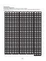
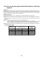
20
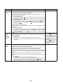
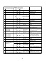
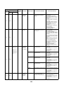
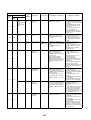
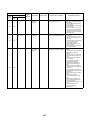
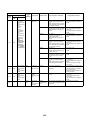
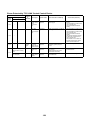
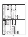
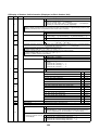
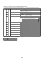
3-2. Outdoor inverter
MMY-MAP0724HT9UL
MMY-MAP0964HT9UL
MMY-MAP1144HT9UL
(60Hz model: MMY-MAP***4HT9UL)
AC600 V / 100 A, 3 P
O
O
O
Relay terminal block for power supply JXO-6003
AC600 V / 60 A, 3 P
O
Relay terminal block for power supply JXO-6003
AC600 V / 60 A, 3 P
Name
Model
Specification
1
Power supply terminal block
HP-T3015-31-3P-L3S
2
3
4
Relay terminal block for reactor
JXO-3006
AC600 V / 30 A, 6 P
5
Communication terminal block
JXO-B2H
AC30 V (or no more than DC42 V) / 1 A, 6 P
O
6
Reactor (For comp.)
CH-80
1.4 mH / 25 A
7
Reactor (For fan)
CH-55
5.8 mH / 14 A
8
Noise Filter P.C. board (MCC-1608)
MCC-1608
9
Line Filter
Inverter P.C. board for Compressor
[A3 IPDU] (MCC-1595)
12 Fuse (MCC-1595)
—
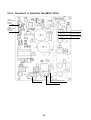
Inverter P.C. board for fan [FAN
IPDU] (MCC-1610)
O
O
O
O
O
O
O
O
O
O
O
O
O
O
O
O
—
O
O
O
—
O
O
O
0.9 mH / AC500 V / 65 A
MCC-1595
CES15 30AF924
13 Comp. Motor drive IPM (MCC-1595) PS21A79
14
O
O
—
Interface P.C. board [Outdoor control MCC-1606
10
P.C. board] (MCC-1606)
11
O
O
MCC-1610
30 A / AC250 V (P.C. board)
O
O
O
50 A / DC600 V (P.C. board)
O
O
O
O
O
O
—
15 Fuse (MCC-1610)
CES15 15AF924
15 A / AC250 V (P.C. board)
O
O
O
16 Fan motor drive IPM (MCC-1610)
FSBB20CH60C
20 A / DC600 V (P.C. board)
O
O
O
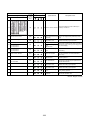
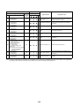
17 Pipe temp. sensor (TD)
—
-30 °C – 135 °C (Ambient temp. range)
O
O
O
18 Pipe temp. sensor (TS)
—
-20 °C – 80 °C (Ambient temp. range)
O
O
O
19 Heat exchanger temp. sensor (TE)
—
-20 °C – 80 °C (Ambient temp. range)
O
O
O
20 Outside temp. sensor (TO)
—
-20 °C – 80 °C (Ambient temp. range)
O
O
O
21 Oil temp. sensor (TK)
—
-30 °C – 135 °C (Ambient temp. range)
O
O
O
22 Liquid temp. sensor (TL)
—
-20 °C – 80 °C (Ambient temp. range)
O
O
O
21
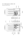
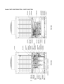
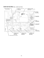
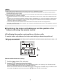
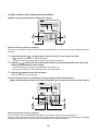
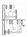
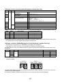
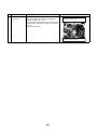
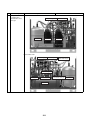
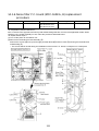
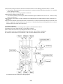
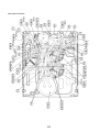
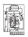
3-3. Parts layout in outdoor unit
Model: MMY-MAP0724HT9UL
22
Model: MMY-MAP0964HT9UL, MAP1144HT9UL
23
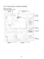
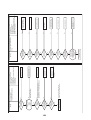
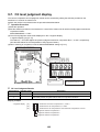
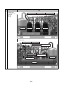
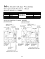
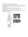
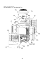
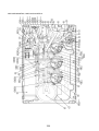
3-4. Parts layout in inverter assembly
Outdoor Unit (6ton)
Model: MMY-MAP0724HT9UL
24
Outdoor Unit (8, 10ton)
Model: MMY-MAP0964HT9UL, MAP1144HT9UL
25
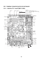
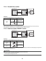
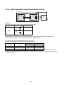
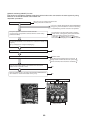
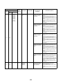
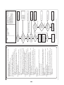
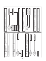
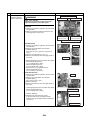
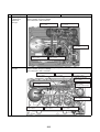
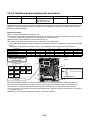
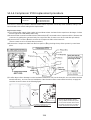
3-5. Outdoor (inverter) print circuit board
3-5-1. Interface P.C. board (MCC-1606)
Sensor input
PMV4 output
PMV2 output
PMV1 output
CN303
CN301
CN300
TD3
TD2
TD1
Option input/output
CN511
CN508
CN514
CN510
CN509
CN513
CN512
CN504
CN503
CN502
TK3
TK2
TK1
CN533
CN532
CN531
TL1
CN523
TO
TK5
TK4
CN507
CN535 TE2
CN534 TE1
CN521
CN520
High pressure SW
CN305, 306, 307
UART communication
CN600
SW04,05,15
7-segment LED
SW06,07,09,10
SW11,12,13,14
SW01,02,03
PD sensor
SW16,17
CN501
Jumper select
PS sensor
CN500
SW30
For inter-unit cable between
indoor and outdoor units
CN01
For inter-unit cable
between outdoor units
CN03
Dyna-doctor
connecting terminal
CN800
4-way valve output
CN317
Accumulator heater
CN334
SV61,62
CN315
Comp. case heater 3
CN333
Comp. case heater 2
CN332
Comp. case heater 1
SV43
CN331
CN313
SV42, SV41
CN312
SV51,52
CN314
SV2
CN311
SV3A
SV3B
SV3C
SV3E
SV3D
CN322
CN321
26
B. Heater
SV3F
CN323
SV12
CN320
CN335
TS1
CN505
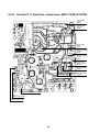
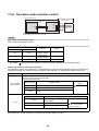
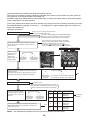
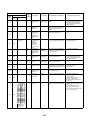
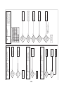
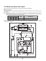
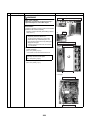
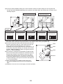
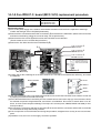
3-5-2. Inverter P.C. board for compressor (MCC-1595) A3-IPDU
Power supply
input L3
CN03
Power supply
input L2
CN02
Power supply
input L1
CN01
Reactor connecting
terminal
CN04
Reactor connecting
terminal
CN05
Compressor
output U-phase
CN201
Compressor
output V-phase
CN202
Compressor
output W-phase
CN203
SW800 For inverter address setting
CN851
UART communication
CN852
UART communication
27
3-5-3. Inverter P.C. board for fan (MCC-1610)
CN702
CN505
CN705
Fan motor output U-phase
CN704
CN705
Fan motor output V-phase
CN703
CN704
Fan motor output W-phase
CN703
CN511
CN510
UART
communication
between
A3-IPDU
CN505
CN504
CN502
UART
communication
between
interface
CN504
CN602
CN500
Reactor connecting terminal
Power supply input
CN500
Reactor connecting terminal
CN511
28
CN510
4
Refrigerant Piping Systematic Drawing
Model: MMY-MAP0724HT9UL
Fan
M
Fan motor
Right side
(TO)
Heat exchanger
Left side
Heat exchanger
(TE1)
SV
(SV5)
PMV1
Reducer
4-way valve
PMV2
(TS1)
Check valve
High-pressure sensor
Low-pressure sensor
SV
(TL)
FP
Fusible
plug
(SV2)
Fusible
plug
(SV3D)
FP
Oil separator
SV
Check
valve
SV (SV41)
High-pressure
switch
(TD1)
Liquid tank
Check
valve
SV (SV42)
High-pressure
switch
(TD2)
Accumulator
SV
(SV3C)
Compressor
A3
1
(Inverter)
(TK4)
Check
valve
Compressor
2
(Inverter)
Check
valve
(TK2)
(TK1)
SV
Oil header
(TK5)
(SV3A)
SV
(SV3E)
Check valve
SV
(SV3B)
Liquid side
packed valve
Gas side
service valve
Balance pipe
packed valve
Symbol
Check valve
SV
Solenoid
valve
Capillary
tube
29
Check
valve
Check joint
Strainer
Temperature Distributor
sensor
Model: MMY-MAP0964HT9UL, MMY-MAP1144HT9UL
Fan
M
Fan motor
Right side
(TO)
Main heat exchanger
PMV1
Sub heat exchanger at right side
PMV2
Left side
(TE1)
PMV4
Main heat exchanger
Check valve
(TE2)
Sub heat exchanger at left side
Check valve
4-way valve
High-pressure sensor
(TS1)
(SV6)
SV
SV
Low-pressure sensor
(TL)
Fusible
plug
(SV2)
(SV3D)
FP
Oil separator
Fusible
plug
SV
FP
(SV41)
SV
SV
Liquid tank
(SV3C)
High-pressure
switch
SV
(TD1)
SV
(SV42)
Accumulator
(SV43)
Highpressure
switch
(TD2)
High-pressure
switch
(TD3)
(TK4)
Compressor
1
(Inverter)
Compressor
2
(Inverter)
(TK2)
(TK1)
SV
(TK5)
(TK3)
Oil header
(SV3E)
(SV3F)
SV
SV
(SV3A)
Compressor
3
(Inverter)
Check valve
SV
(SV3B)
Check valve
Gas side
service valve
Balance pipe
packed valve
Symbol
Liquid side
packed valve
SV
Solenoid
valve
Capillary
tube
30
Check
valve
Check joint
Strainer
Temperature Distributor
sensor
Explanation of Functional Parts
Functional part name
Solenoid valve
SV3A
(Connector CN321: White)
1) Supplies oil reserved in the oil header during ON time.
SV3B
(Connector CN321: White)
1) Returns oil supplied in the balance pipe to the compressor.
SV3C
(Connector CN321: White)
1) Pressurizes oil reserved in the oil header during ON time.
SV3D
(Connector CN322: White)
1) Reserves oil in the oil separator during OFF time.
2) Returns oil reserved in the oil separator to the compressor during ON time.
SV3E
(Connector CN322: White)
1) Turns on during operation and balances oil between compressors.
SV3F
(Connector CN323: White)
1) Controls oil level balances between compressors.
SV2
(Hot gas bypass) (Connector CN311: White)
1) Low pressure release function
2) High pressure release function
3) Gas balance function during stop time
SV41
SV42
SV43
(Start compensation valve of compressor)
(SV41 Connector CN312: Blue, SV42 Connector CN312: Blue, SV43 Connector CN313: Red)
1) For gas balance start
2) High pressure release function
3) Low pressure release function
SV5
(Connector CN314: White)
1) Preventive function for high-pressure rising in heating operation
SV6
(Connector CN315: White)
1) Liquid bypass function for discharge temperature release (cooling bypass function)
(Connector CN317:Blue)
1) Cooling/heating exchange
2) Reverse defrost
4-way valve
PMV1, 2
(Connector CN300, 301: White)
1) Super heat control function in heating operation
2) Liquid line shut-down function while follower unit stops
3) Under cool adjustment function in cooling operation
4) Exchange function between main and sub exchangers in cooling operation
PMV4
(Connector CN303: Red)
1) Exchange function between main and sub exchangers in cooling operation
2) Preventive function for high-pressure rising in heating operation
Pulse motor
valve
1) Prevention for rapid decreasing of oil (Decreases oil flowing to the cycle)
2) Reserve function of surplus oil
Oil separator
Temp. Sensor
Functional outline
TD1
TD2
TD3
(TD1 Connector CN502: White, TD2 Connector CN503: Pink, TD3 Connector CN504: Blue)
1) Protection of compressor discharge temp.
2) Used for discharge temperature release
TS1
(Connector CN505: White)
1) Controls PMV super heat in heating operation
TE1
(Connector CN520: Green)
1) Controls defrost in heating operation
2) Controls outdoor fan in heating operation
TE2
(Connector CN521: Red)
1) Controls exchange function between main and sub exchangers
TK1, TK2
TK3, TK4
TK5
(TK1 Connector CN531: Black, TK2 Connector CN532: Green, TK3 Connector CN533: Red, TK4 Connector CN534: Yellow,
TK5 Connector CN535: Red)
1) Judges oil level of the compressor
TL
(Connector CN523: White)
1) Detects under cool in cooling operation
TO
(Connector CN507: Yellow)
1) Detects outside temperature
High pressure
sensor
(Connector CN501: Red)
1) Detects high pressure and controls compressor capacity
2) Detects high pressure in cooling operation, and controls the fan in low ambient cooling operation
3) Detects under cool in indoor unit in heating operation
Low pressure
sensor
(Connector CN500: White)
1) Detects low pressure in cooling operation and controls compressor capacity
2) Detects low pressure in heating operation, and controls the super heat
Compressor
case heater
(Compressor 1 Connector CN331: White, Compressor 2 Connector CN332: Blue, Compressor 3 Connector CN333: Black)
1) Prevents liquid accumulation to compressor
Accumulator
case heater
(Connector CN334: Red)
1) Prevents liquid accumulation to accumulator
Pressure sensor
Heater
Balance pipe
1) Oil balancing in each outdoor unit
31
5
Combined Refrigerant Piping System
Schematic Diagrams
5-1. Normal operation (COOL mode / DEFROST mode) high outside air temperature (roughly 68 °F (20 °C) or
above)
Header unit (MMY-MAP0964HT9UL)
Follower unit (MMY-MAP0724HT9UL)
FM
FM
TO
TO
PMV1
PMV2
TE1
TE1
PMV4
SV
TE2
SV5
PMV1
4-Way valve
Pressure sensor
(high pressure)
PMV2
4-Way valve
TS1
TS1
SV6
SV
Pressure sensor
(low pressure)
Pressure sensor
(high pressure)
SV
SV
TL
TL
Pressure sensor
(low pressure)
SV2
SV3D
O.S.
O.S.
SV3D
SV
SV2
SV
SV
SV3C
HPS
SV
TD1
HPS
SV
SV42
TD2
Liquid tank
HPS
TD1
HPS
SV3C
SV43
TD3
Compressor
2
TK4
SV
TK3
TK2
SV3
TK5
SV3F
SV3A
SV
SV
Compressor
2
TK5
SV3E
SV
SV3B
SV
SV
SV3A
Accumulator
Compressor
3
TK1
TK2
TK1
SV42
TD2
HPS
A3
Compressor
1
TK4
Compressor
1
SV
Accumulator
SV
SV
Liquid tank
SV41
SV
SV41
SV
SV3B
Balance pipe
Liquid pipe
Gas pipe
Gas pipe
Liquid pipe
PMV
TC1
TC2
TCJ
PMV
PMV
TC2
TC1
TC2
TCJ
TCJ
Indoor unit
PMV
TC1
TC2
TC1
TCJ
Note: In DEFROST mode, PMV4 also opens.
High-pressure gas or condensate liquid refrigerant
Evaporative gas refrigerant (low-pressure gas)
Normal refrigerant line
Note: The "header unit" is the outdoor unit to which the indoor-outdoor communication
line is connected. All other outdoor units are called "follower units".
32
(The diagram shows a 168 type as an example.)
5-2. Normal operation (COOL mode) - low outside air
temperature (roughly below 68 °F (20 °C))
Header unit (MMY-MAP0964HT9UL)
Follower unit (MMY-MAP0724HT9UL)
FM
FM
TO
TO
PMV1
PMV2
TE1
TE1
PMV4
SV
TE2
SV5
PMV1
4-Way valve
Pressure sensor
(high pressure)
PMV2
4-Way valve
TS1
TS1
SV6
SV
Pressure sensor
(low pressure)
Pressure sensor
(high pressure)
SV
SV
TL
TL
SV3D
Pressure sensor
(low pressure)
SV2
O.S.
SV2
O.S.
SV3D
SV
SV
SV
SV3C
HPS
SV
TD1
HPS
SV
SV42
TD2
Accumulator
Liquid tank
SV43
TD3
HPS
SV
HPS
SV3C
Compressor
2
TK4
Compressor
2
SV
SV3E
TK2
TK5
TK5
SV3E
SV3F
SV3A
SV
SV
TK3
SV
SV3B
SV
SV
SV3A
Accumulator
Compressor
3
TK1
TK2
TK1
SV42
TD2
HPS
A3
Compressor
1
TK4
Compressor
1
TD1
SV
SV
Liquid tank
SV41
SV
SV41
SV
SV3B
Balance pipe
Liquid pipe
Gas pipe
Gas pipe
Liquid pipe
TC2
TC1
TCJ
TC2
PMV
PMV
PMV
PMV
TC1
TC2
TCJ
TCJ
TC1
TC2
TC1
TCJ
Indoor unit
High-pressure gas or condensate liquid refrigerant
Evaporative gas refrigerant (low-pressure gas)
Note: With a 096 type or 114 type outdoor unit, the main heat exchanger and subheat exchanger may be switched over depending on the outside temperature
and air conditioning loads.
Normal refrigerant line
Note: The "header unit" is the outdoor unit to which the indoor-outdoor communication
line is connected. All other outdoor units are called "follower units".
33
(The diagram shows a 168 type as an example.)
5-3. Normal operation (HEAT mode)
Header unit (MMY-MAP0964HT9UL)
Follower unit (MMY-MAP0724HT9UL)
FM
FM
TO
TO
PMV1
PMV
TE1
TE1
PMV4
SV
TE2
SV5
PMV1
4-Way valve
Pressure sensor
(high pressure)
PMV2
4-Way valve
TS1
TS1
SV6
SV
Pressure sensor
(low pressure)
Pressure sensor
(high pressure)
SV
SV
TL
TL
SV3D
Pressure sensor
(low pressure)
SV2
O.S.
SV3D
SV
SV2
O.S.
SV
SV
SV
SV3C
HPS
SV
SV42
Accumulator
Liquid tank
TD2
HPS
HPS
SV
HPS
SV3C
SV43
TD3
Compressor
2
TK4
Compressor
2
SV
SV3E
TK2
TK5
TK5
SV3E
SV3F
SV3A
SV
SV
TK3
SV
SV3B
SV
SV
SV3A
Accumulator
Compressor
3
TK1
TK2
TK1
SV4 2
TD2
HPS
A3
Compressor
1
TK4
Compressor
1
TD1
SV
TD1
SV
Liquid tank
SV41
SV
SV41
SV
SV3B
Balance pipe
Liquid pipe
Gas pipe
Gas pipe
Liquid pipe
PM
TC1
TC2
TC
J
PMV
PMV
TC1
TC2
TC1
TC2
TCJ
PMV
TCJ
TC1
TC
TCJ
Indoor unit
High-pressure gas or condensate liquid refrigerant
Evaporative gas refrigerant (low-pressure gas)
Normal refrigerant line
Note: The "header unit" is the outdoor unit to which the indoor-outdoor communication
line is connected. All other outdoor units are called "follower units".
34
(The diagram shows a 168 type as an example.)
5-4. Emergency operation (cooling operation under
header outdoor unit backup scenario)
Leakage from PMV:
Liquid-side service valve
= Full closure
Set Up as Temporary
Header Unit during
Emergency Operation
Failure
Header unit (MMY-MAP0964HT9UL)
Follower unit (MMY-MAP0964HT9UL)
FM
FM
TO
PMV1
TO
PMV1
PMV2
PMV2
TE1
PMV4
TE1
PMV4
TE2
TE2
4-Way valve
4-Way valve
Pressure sensor
(high pressure)
Pressure sensor
(high pressure)
TS1
SV6
TS1
SV6
SV
SV
SV3D
SV
Pressure sensor
(low pressure)
SV2
O.S.
TL
SV3D
O.S.
SV
SV
SV41
SV41
SV
SV
TD1
SV3C
HPS
SV
Liquid tank
HPS
SV
SV42
TD2
Accumulator
SV
Compressor
1
HPS
TD1
HPS
TD2
HPS
Accumulator
SV43
TD3
HPS
TK2
Compressor
1
Compressor
3
TK2
TK1
TK3
SV
TK5
SV3E
SV
Compressor
2
SV
SV
SV3A
TK3
TK5
SV3E
SV3F
SV
Compressor
3
SV3F
SV
SV
SV
SV42
TK4
Compressor
2
TK1
SV
SV3C
Liquid tank
SV43
TD3
TK4
SV3A
Pressure sensor
(low pressure)
SV2
SV
TL
SV
SV3B
SV
SV3B
Balance pipe
Liquid pipe
Gas pipe
Gas-side service valve
= Full closure
Balance pipe packed valve
= Full opening
Gas pipe
Liquid pipe
PMV
PMV
TC2
TCJ
TC
TC2
PMV
TC1
TC2
TCJ
TCJ
PMV
TC1
TC2
TC1
TCJ
Indoor unit
High-pressure gas or condensate liquid refrigerant
Evaporative gas refrigerant (low-pressure gas)
Normal refrigerant line
Refrigerant recovery line
Note: The "header unit" is the outdoor unit to which the indoor-outdoor communication
line is connected. All other outdoor units are called "follower units".
35
(The diagram shows a 192 type as an example.)
5-5. Emergency operation (heating operation under
header outdoor unit backup scenario)
Set Up as Temporary
Header Unit during
Emergency Operation
Leakage from PMV:
Liquid-side service valve
= Full closure
Failure
Header unit (MMY-MAP0964HT9UL)
Follower unit (MMY-MAP0964HT9UL)
FM
FM
TO
TO
PMV1
PMV1
PMV2
PMV
TE1
PMV4
TE1
PMV
TE2
TE2
4-Way valve
Pressure sensor
(high pressure)
4-Way valve
Pressure sensor
(high pressure)
TS1
SV6
TS1
SV6
SV
SV
SV3D
SV
Pressure sensor
(low pressure)
SV2
O.S.
TL
SV3D
SV
O.S.
SV
SV41
SV41
SV
SV
SV
SV42
SV3C
Liquid tank
HPS
SV
TD1
TD2
HPS
Accumulator
SV
HPS
SV
Liquid tank
SV43
TD3
TD1
SV3C
HPS
TK4
Compressor
2
TK2
HPS
Accumulator
SV43
TD3
Compressor
1
Compressor
3
Compressor
2
TK2
TK1
TK3
SV
TK5
SV3E
SV
SV
SV3A
SV
TK3
TK5
SV3E
SV3F
SV
Compressor
3
SV3F
SV
SV
TK1
TD2
HPS
SV
SV42
TK4
Compressor
1
SV3A
Pressure sensor
(low pressure)
SV2
SV
TL
SV
SV3B
SV
SV3B
Balance pipe
Liquid pipe
Gas-side service valve
= Full closure
Gas pipe
Balance pipe packed valve
= Full opening
Gas pipe
Liquid pipe
PMV
PMV
TC2
TCJ
TC1
TC2
PMV
TC1
TC2
TCJ
TCJ
PMV
TC1
TC2
TC1
TCJ
Indoor unit
High-pressure gas or condensate liquid refrigerant
Evaporative gas refrigerant (low-pressure gas)
Normal refrigerant line
Refrigerant recovery line
Note: The "header unit" is the outdoor unit to which the indoor-outdoor communication
line is connected. All other outdoor units are called "follower units".
36
(The diagram shows a 192 type as an example.)
5-6. Refrigerant recovery from failed outdoor unit (pumpdown operation under follower outdoor unit backup
scenario)
Failure
Header unit (MMY-MAP0964HT9UL)
Follower unit (MMY-MAP0724HT9UL)
FM
FM
TO
TO
PMV1
PMV2
TE1
TE1
PMV4
SV
TE2
SV5
PMV1
4-Way valve
Pressure sensor
(high pressure)
PMV2
TS1
TS1
SV6
Liquid line bypass
SV
SV
TL
TL
4-Way valve
SV3D
SV
Pressure sensor
(low pressure)
SV2
O.S.
Pressure sensor
(high pressure)
SV2
O.S.
SV3D
SV
Pressure sensor
(low pressure)
SV
SV
SV
SV42
HPS
SV
SV3
Liquid tank
TD2
HPS
TD1
Liquid
tank
TK
Compressor
1
Compressor
2
HPS
SV3C
SV43
TD3
HPS
SV
Accumulator
A3
Compressor
1
TK4
Compressor
2
TK2
SV
SV3E
TK5
TK5
SV3E
SV3F
SV
SV
TK3
SV
SV3A
SV3B
SV
SV
SV3A
Accumulator
Compressor
3
TK1
TK2
TK1
SV42
TD2
HPS
SV
SV
TD1
SV41
SV
SV41
SV
SV3B
Balance pipe packed valve
= Full opening
Balance pipe
Liquid pipe
Gas-side service valve = Full opening
⇒ Full closure 10 minutes after system startup
Gas pipe
Liquid-side service valve
= Full closure
Gas pipe
Liquid pipe
PMV
TC2
TCJ
TC1
TC2
PMV
PMV
PMV
TC1
TC2
TCJ
TCJ
TC1
TC2
TC1
TCJ
Indoor unit
High-pressure gas or condensate liquid refrigerant
Evaporative gas refrigerant (low-pressure gas)
Normal refrigerant line
Refrigerant recovery line
Note: The "header unit" is the outdoor unit to which the indoor-outdoor communication
line is connected. All other outdoor units are called "follower units".
37
(The diagram shows a 168 type as an example.)
6
Control Outline
Outdoor unit
Description of operation, numerical data, and other information
Remarks
1. PMV1, 2 control (PMV1 and 2)
1) During air conditioner operation, the pulse count of a PMV (pulse motor valve) is
controlled between 90 and 1000.
2) During cooling, the PMV opening is controlled on the basis of measurements
provided by the TL temperature sensor and the Pd pressure sensor (under cool
control).
3) During heating, the PMV opening is controlled on the basis of measurements
provided by the TS and TD temperature sensors and the PS pressure sensor
(super heat control).
4) PMVs are fully closed when the air conditioner is in thermo OFF state or upon
being turned off normally or shut down due to an abnormality.
• During heating, PMV control
may be provided with PMV1
alone, operated at 45 pulses
(minimum), with PMV2
turned off.
Opening of PMV1, 2
1000
PMV 2
550
500
90
45
PMV 1
Minimum
Maximum
2. PMV4 control (applicable only to MMY-MAP0964HT9UL, MMY-MAP1144HT9UL)
1) When using a small-capacity split-type heat exchanger (mainly a sub-heat
exchanger to a combination of a sub-heat exchanger and main heat exchanger)
during cooling, the pulse count of the PMV (pulse motor valve) is controlled
between 45 and 500.
The PMV4 opening is controlled on the basis of measurements provided by the
TE1 and TE2 temperature sensors.
2) During heating, the PMV4 may be used as a pressure-relief bypass valve by
opening it to a certain degree.
500
Opening of PMV4
Item
1. Pulse
motor valve
(PMV)
control
PMV 4
45
Minimum
Maximum
38
Item
2. Outdoor
fan control
Description of operation, numerical data, and other information
Remarks
1. Cooling fan control
1) Outdoor fan speed (mode) is controlled on the basis of measurements provided by
the Pd pressure sensor.
2) For a specified period after the start of cooling operation, the header outdoor unit
controls outdoor fan speed (mode) on the basis of measurements provided by the
Pd pressure sensor. Follower units, on the other hand, control outdoor fan speed
(mode) on the basis of measurements provided by the TE1 temperature sensor.
Pd
pressure
3.0
[Current mode + 1]
(Mode raised as rapidly
as every second)
[Highest mode]
2.65
[Current mode + 1]/50 seconds
2.45
[Current mode + 1]/75 seconds
(Mode raised up to 13)
[Hold]
2.35
(Mode 1 to highest)
2.15
2.00
Mode being raised: mode 0 → 1
[Current mode - 1]/50 seconds
Mode being lowered:
Highest mode - 1 → 1
1.95
[Current mode - 1]
(Mode lowered as rapidly as
every two seconds)
(down to mode 0)
Interval control
[Mode [0]: 180 seconds
Mode [1]: 30 seconds]
• The fan speed
corresponding to the highest
mode varies with the HP
capacity of the outdoor unit.
* Available control modes are 0 (at rest) to 63.
2. Heating fan control
1) Outdoor fan speed (mode) is controlled on the basis of measurements provided by
the TE1 temperature sensor.
2) If TE1 > 25°C is continuously detected for 8 minutes, the fan may be turned off.
However, this condition is the same as normal thermo OFF, so that fan operation
will be restarted.
3) For a specified period after air conditioner startup and during defrosting, this
control is disabled.
4) When refrigerant is in extremely short supply, this control may cause the air
conditioner to be repeatedly turned on and off.
TE1 temperature
°F (°C)
Zone A: Lowest mode, timer count for forced compressor shutdown
77 (25)
Zone B: -2/15 seconds (down to lowest mode)
46.4 (8)
Zone C: -1/15 seconds (down to lowest mode)
42.8 (6)
Zone D: Hold (staying at current mode)
39.2 (4)
Zone E: +1/15 seconds (up to highest mode)
35.6 (2)
Zone F: Highest mode
3. Control while follower unit at rest
The fan is operated at mode 1 to prevent the accumulation of refrigerant inside the
outdoor heat exchanger.
3. Capacity
control
1) The compressors of the header and follower units are controlled on the basis of
capacity demand issued by indoor controllers.
2) The two or three compressors featured in an outdoor unit operate on a rotational
basis, so that, every time they come to a stop, their order of startup changes.
3) Where two or more follower units are connected, every time the system goes
thermo OFF or all the compressors featured in the follower units come to a stop,
the priority startup order of the follower units changes, as they are also subject to
rotational operation.
39
• The fan speed
corresponding to the highest
mode varies with the HP
capacity of the outdoor unit.
Remarks
• Oil level detection takes
1) Judgment as to whether an optimum amount of oil is present in the compressor
place regardless of the
cases is made on the basis of the temperature readings of sensors TK1 to TK5.
number of compressors,
This control function is performed by the header unit and each follower unit
whether it be one, two or
individually.
three.
2) In concrete terms, judgment is based on the relationship between the temperature • Rough guide for oil level
measurements provided by TK1, TK2 or TK3, on the one hand, and those provided
judgment
1) If TK1 - TK4 57.2 °F
by TK4 or TK5, on the other. If there is depletion, oil equalization control takes over.
(14 °C),
3) This control function is performed whenever at least one compressor is in
oil level of compressor 1
operation.
is optimum.
2) If TK2 - TK4 57.2 °F
SV
(14 °C),
oil level of compressor 2
is optimum.
(SV2)
Oil
separator
(SV3D)
3) If TK3 - TK4 57.2 °F
(14 °C),
SV
oil level of compressor 3
is optimum.
OFF
OFF
(SV41)
SV
SV
OFF
SV
(TD1)
High (SV3C)
pressure
SW
High
pressure
SW
SV
(SV42)
OFF
(TD2)
High
pressure
SW
(SV43)
(TD3)
(TK4)
Compressor
1
(inverter)
Compressor
2
(inverter)
(TK5)
ON
(SV3A)
Compressor
3
(inverter)
(TK2)
(TK1)
SV
4. Oil level
detection
control
Description of operation, numerical data, and other information
(TK3)
Oil header
(SV3E)
SV
(SV3F)
ON
SV
Item
OFF
OFF
SV
Check valve
(SV3B)
Check valve
Balance pipe
Packed valve
40
OFF
Item
5. Oil
equation
control
Description of operation, numerical data, and other information
Remarks
This control function is aimed at preventing compressors from running out of oil by
evening out the oil supply to outdoor units, and is basically performed by opening/
closing solenoid valves SV3A, SV3B, SV3C, SV3D, and SV3F. There are three control
patterns as described below. (For a schematic diagram of oil equalization control, see
page 46.)
1. Preparatory control
If the oil level judgment result in the memory continues to be “low” for 30 seconds,
SV3B is turned on, with SV3D turned on and off intermittently.
• Oil accumulated in the oil
separator is returned to the
compressor.
• This is normal oil
2. Oil equation control
equalization control.
This control function is performed to transfer oil to the outdoor unit whose oil level is
low from other outdoor units. It takes place whenever the header unit registers a low
oil level result while at least one of its compressors is turned on or at least one of the
follower units issues an oil level equation request.
This control function does not apply to a header unit-only system (no follower units
connected).
• This protective control is
3. Oil depletion protection control
performed when a
This control function is performed if oil equation control fails to achieve an optimum
prolonged low oil level is
oil level. In concrete terms, if a low oil level situation continues for 30 minutes, the unit
detected.
is brought to a protective shutdown, followed by a restart 2 minutes and 30 seconds
later. If protective shutdown is repeated three times, the error is confirmed as final.
(There will be no more restarts.) The error code is “H07”.
6.
Refrigerant/
oil recovery
control
• Cooling oil recovery control
1. Cooling oil (refrigerant) recovery control
takes place approximately
Performed during cooling, this control function aims to: periodically collect any
every 2 hours.
refrigerating oil condensate that has built up in inter-unit gas pipes and indoor units
• Control duration is about 2 to
and return it to outdoor units when the compressor operation command is
5 minutes, though it varies
inadequate; and prevent the accumulation of refrigerant in outdoor heat exchangers
according to the operating
while cooling operation is in progress under low outside air temperature conditions.
conditions of the system.
It is managed by the header outdoor unit.
1) Control commencement conditions
• When cooling operation has continued for at least 2 hours
• When cooling operation has started (compressors have just been turned on, though
this does not always happen depending on outside air temperature conditions).
2) Control details
• All compressors currently in operation are operated at the minimum speed, with those
currently not in operation turned on.
• Indoor units are set to the cooling oil (refrigerant) recovery control mode, with their
indoor PMVs opened to a certain degree.
• Compressors are operated at the target speed.
• After recovery control is performed for a specified period of time, it is terminated, and
normal cooling operation resumes.
• Heating oil recovery control
2. Heating refrigerant (oil) recovery control
takes place approximately
Performed during heating, this control function aims to recover any liquid refrigerant
every hour.
trapped inside indoor units that have been turned off. It also serves the additional
• Control duration is about 2 to
purposes of recovering indoor/outdoor refrigerant after defrosting and recovering oil
10 minutes, though it varies
present in outdoor heat exchangers during heating overload operation.
according to loading
This control function is managed by the header outdoor unit.
conditions.
• Compressor rotational
1) Control commencement conditions
• When heating operation has started (compressors have just been turned on)
• When heating takes over upon completion of defrosting
• When heating operation has continued for 60 minutes
2) Control details
• All compressors currently in operation are operated at the minimum speed, with those
currently not in operation turned on.
• Indoor units are set to the heating refrigerant (oil) recovery control mode, with their
indoor PMVs opened to a certain degree.
• Compressors are operated at the target speed.
• Upon completion of refrigerant recovery for all the indoor units, normal cooling
operation resumes.
41
speed varies with control
conditions, indoor unit
capacity, and outdoor unit
specification.
Item
7. Defrosting
control
(reverse
defrosting
method)
Description of operation, numerical data, and other information
Remarks
• Frost formation temperature
1. Defrosting commencement conditions
is 29.3 °F (-1.5 °C).
• During heating operation, the cumulative duration of operation in which TE1 sensor
• If the outdoor units are a
temperature falls below frost formation temperature is measured, and when this
combination of different
reaches 55 minutes, defrosting control is introduced. (Just after startup or upon
models, defrosting
changeover from cooling to heating, the target cumulative duration is 25 minutes.)
operation, once started,
* If the outdoor units are a combination of different models, all the units begin engaging
cannot be manually
in defrosting control as soon as one of them satisfies defrosting commencement
terminated for about 2
conditions.
minutes.
• To protect the refrigerating
2. Details of defrosting control
cycle circuit, the fan mode
1) All compressors currently in operation are operated at the minimum speed.
may be controlled during
2) When a specified amount of time passes from the time the compressors reached
defrosting.
the minimum speed, the outdoor fans are turned off by closing the 4-way valves.
3) All compressors currently not in operation are turned on and operated at the target
rotational speed for defrosting control.
• During defrosting control,
3. Defrosting termination conditions
compressors are controlled
• Defrosting termination conditions are met when the TE1 temperature sensor
so that their speeds do not
measurement reaches a specified value (roughly 53.6 °F (12 °C)) a certain period
exceed 76.6 rps.
of time after the commencement of defrosting control. In that event, defrosting
termination control takes over.
* If the outdoor units are a combination of different models, defrosting termination
control commences when all the units satisfy the defrosting termination conditions.
As long as one or more outdoor units are yet to satisfy the defrosting termination
conditions, those that have engage in standby operation.
4. Details of defrosting termination control
1) Compressors are operated at the standby operation speed.
2) When a specified amount of time passes, the 4-way valves are opened.
3) Indoor heating refrigerant recovery control is performed.
For control details, see “ 6. Refrigerant/oil recovery control”.
42
• During standby operation,
compressor speed is in the
24-33.5 rps range.
(It varies from outdoor unit to
outdoor unit.)
Item
Description of operation, numerical data, and other information
8. Release
valve control
1. SV2 gas balance control
This control function is aimed at achieving gas balance by opening SV2 while
compressors are turned off so as to reduce their startup load the next time they are
turned on. It is individually performed by the header outdoor unit and each follower
outdoor unit.
1) Control conditions
• In cooling, compressors have been turned off.
• In heating, the header unit has been shut down.
2) Control details
• The control point is changed according to 'P (Pd pressure - Ps pressure) registered
just before the compressors were turned off.
• When 'P P1, SV2 is opened. When this results in 'P < P2, SV2 is closed.
• When 'P < P1, SV2 is closed.
(Unit: psi (MPa))
Heating
Control points
for Pd
pressure
P1, P2
Cooling
Header unit compressors
Header unit compressors
OFF
OFF
Header unit compressors
ON
P1
P2
P1
P2
P1
P2
Header unit
188.5 (1.3)
159.5 (1.1)
188.5 (1.3)
159.5 (1.1)
—
—
Follower unit
188.5 (1.3)
159.5 (1.1)
188.5 (1.3)
159.5 (1.1)
72.5 (0.5)
58.0 (0.4)
2. SV2 high pressure release control
This control function is aimed at mitigating pressure rise while a compressor is in
operation at low speeds.
1) Control conditions
• Heating operation is in progress (except periods of defrosting control).
• A lone compressor from the header unit is in operation at low speeds of up to 36 rps.
2) Control details
• When Pd pressure becomes
• When Pd pressure becomes
493 psi (3.4 MPa), SV2 is opened.
406 psi (2.8 MPa), SV2 is closed.
3) Termination conditions
•
•
•
•
Shutdown, thermo OFF, defrosting operation, or cooling operation.
The number of header unit compressors in operation increases to two or more.
At least one follower unit compressor is turned on.
The speed of the compressor rises to 40 rps or more.
3. SV2 low pressure release control
This control function is aimed at preventing a rapid fall in pressure during transient
operation. It is individually performed by the header outdoor unit and each follower
outdoor unit.
The control is always provided except during periods of stoppage or thermo OFF.
1) Control details
• When Ps pressure becomes 23.2 psi (0.16 MPa), SV2 is opened.
• When Ps pressure becomes > 29 psi (0.20 MPa), SV2 is closed.
43
Remarks
Item
Description of operation, numerical data, and other information
8. Release
valve control
(cont’d)
4. SV41, 42, 43 low pressure release control
This control function is aimed at providing low pressure protection, and is individually
performed by the header unit and each follower unit.
The control takes place during defrost operation, heating startup pattern control
operation, and cooling operation.
1) Control details (heating)
When Ps pressure becomes 14.5 psi (0.1 MPa), SV41, 42 and 43 are opened;
when Ps pressure becomes 21.8 psi (0.15 MPa), SV41, 42 and 43 are closed.
2) Control details (cooling)
When Ps pressure and Pd pressure become 20.3 psi (0.14 MPa) and 261 psi
(1.8 MPa), respectively, SV41 and 42 are opened; when Ps pressure and Pd
pressure become 27.6 psi (0.19 MPa) and 319 psi (2.2 MPa), respectively,
SV41 and 42 are closed.
5. SV5 high pressure release control
This control function is aimed at mitigating pressure rise and is only performed by the
header unit.
1) Control details (heating)
When Pd pressure and compressor speed become 493 psi (3.4 MPa) and 38
rps, respectively, during heating, with a single compressor in operation, SV5 is
opened; when Pd pressure becomes 391.5 psi (2.7 MPa), or compressor speed
64 rps, SV5 is closed.
9. High
pressure
release
compressor
shutdown
control
This control function is aimed at automatically shutting down a compressor in an
outdoor unit depending on Pd pressure. It is individually performed by the header unit
and each follower unit.
1) Control details
10. Case
heater
control
There are two types of case heaters: a compressor case heater and an accumulator
case heater. This control function is aimed at preventing the accumulation of refrigerant
in those cases, and is performed by all outdoor units.
If the power supply has not been turned on for a specified period before a postinstallation test run, compressor failure may occur. Similarly, when starting
compressors after a long period of no power supply, it is recommended that the power
supply be turned on for a while before operation is resumed, just like a post-installation
test run.
This control function is sometimes used alongside an electrical charging of the
compressor motor windings. In this case, a charging sound may be heard, but this is
normal.
1) Control details
Remarks
• When Pd P0 = 500.3 psi
(3.45 MPa), compressor No.
2 or No. 3 (the last one of
three compressors in terms
of startup order in a three
• Compressors are shut down when Pd pressure reaches or exceeds P0.
compressor configuration) is
• The compressor restart prevention timer (2 minutes 30 seconds) is set, and the control
shut down.
terminated.
• When Pd P0 = 507.5 psi
(3.5 MPa), compressor No.
1 (the first compressor in
terms of startup order) is
shut down.
• The heaters are turned on while the compressors are turned off.
• The heaters are turned off when T0 sensor temperature becomes 82.4 °F (28 °C),
and are turned back on when T0 sensor temperature becomes 77 °F (25 °C).
• When the compressors are turned on, the heaters are kept on for 10 minutes.
44
Item
11. A3-IPDU
control
Description of operation, numerical data, and other information
Remarks
IPDU controls inverter compressors by issuing commands relating to compressor
speeds, speed increases/decreases, and current release control values via the
interface P.C. board.
The main control functions of the IPDU P.C. board are described below.
1. Current release control
To prevent inverter input current from exceeding the specified value, output
frequency is controlled with AC input current as detected by T02 mounted on the
control P.C. board.
Current
Zone B
I1
Zone C
Zone D
I2
Zone A
Zone A:Compressors are operated normally.
Zone D:The current operating frequency is maintained.
Zone B:Operating frequency is lowered.
Zone C:The lowering of operating frequency is halted
to maintain the current frequency.
Current control values for various outdoor units are shown below.
Outdoor unit
capacity type
I1
I2
114
14.0
13.5
096
13.2
12.7
072
14.0
13.5
• A3-IPDU1, 2 and 3 are each
2. Heat sink temperature detection control
provided with a TH sensor.
1) This control function is aimed at protecting IGBT from overheating via a thermistor
(TH sensor) mounted in the compressor drive module (Q201) of A3-IPDU.
2) When TH 185 °F (85 °C) is detected, the fan operation mode is raised by one
step, followed by a series of additional step-ups right up to the highest mode at a
rate of one step/5 seconds.
3) After step 2), the normal fan mode is restored when TH falls to < 185 °F (85 °C).
4) When TH 221 °F (105 °C), compressors are shut down.
5) Compressors are restarted 2 minutes and 30 seconds later, with an error count of
1 recorded. If this is repeated four times (error count reaches 4), the error is
confirmed as final. The error [P07] is displayed. (There will be no more restarts.)
* Possible causes of the confirmed error include a heat buildup in the outdoor unit, fan
abnormality, blockage of the cooling duct, and IPDU P.C. board fault.
* The TH temperature used in this control function is the highest registered by A3IPDU1, A3-IPDU2, and A3-IPDU3.
3. Overcurrent protection control
1) When the overcurrent protection circuit on an IPDU P.C. board detects an
abnormal current, the compressor is shut down.
2) The compressor is restarted 2 minutes and 30 seconds later, with an error count
of 1 recorded. If the compressor successfully operates for at least 10 minutes after
a restart, the error count is cleared.
3) If the error count reaches 8, the error is confirmed as final.
4. High pressure SW control
1) When the high pressure SW of an inverter compressor is activated, the
compressor is shut down with an error count of 1 recorded.
2) The compressor is restarted 2 minutes 30 seconds later, and, if it successfully
operates for at least 10 minutes, the error count is cleared.
3) If the error count reaches 4, the error is confirmed as final. The error “P04” is
displayed.
45
• Connected to A3-IPDU, the
high-pressure SW is
normally closed.
<Other points to note>
1
Cooling operation under low outside temperature conditions
1) If pressure falls to extremely low levels, indoor units may be shut down via freeze prevention control based
on the indoor TC sensor.
2) If pressure falls to extremely low levels, frequency may be reduced via cooling capacity control.
3) When the discharge temperature sensor reading falls below 140 °F (60 °C), the frequency may be
increased above the level called for by the command received from the indoor unit.
2
PMV (Pulse Motor Valve)
1) When the power is turned on, PMVs generate a tapping sound as they are initialized. If this sound is not
heard, there is a possibility of faulty PMV operation. However, in a noisy environment, it may simply be
drowned out by ambient noise.
2) Do not separate the actuator (head section) from any PMV during operation. It may result in an inaccurate
opening.
3) When transporting (relocating) the set, do not, under any circumstances, keep the actuator separated. It
may damage the valve by causing it to close and exposing it to pressure from sealed liquid.
4) When reattaching the actuator after its removal, push it in firmly until a click sound is heard. Then, turn the
power off and back on again.
<Schematic diagram for oil equation control>
Unit
transferring oil
Unit
receiving oil
Header unit (MMY-MAP0964HT9UL)
Follower unit (MMY-MAP0724HT9UL)
FM
FM
TO
TO
PMV2
TE1
TE1
PMV4
SV
TE2
SV5
PMV2
4-way valve
4-way valve
PMV1
High pressure sensor
TS1
TS1
SV6
SV
Low pressure sensor
High pressure sensor
SV
SV
TL
TL
SVD3
SV2
O.S.
Low pressure sensor
SV2
O.S.
SV3D
SV
SV
SV41
SV
SV41
TD1
SV
SV
SV42
Liquid tank
TD2
HPS
HPS
SV3C
HPS
A3
Compressor
1
TK
Compressor
1
TD1
SV43
TD3
HPS
SV
Compressor
2
TK4
Compressor
2
SV3
SV
TK3
TK2
TK5
TK5
SV3E
SV
SV3F
SV3A
SV
SV3A
ON
Accumulator
SV
SV
TK2
TD2
Compressor
3
TK1
TK1
SV42
Accumulator
SV
Liquid tank
ON
SV3C
HPS
SV
SV
SV
PMV1
SV
SV3B
Balance pipe
Liquid pipe
Gas pipe
46
SV3B
ON
7
Applied Control and Functions
7-1. Applied control for outdoor unit
The outdoor fan high static pressure support and priority operation mode setting (cooling / heating / number of units
/ or priority indoor unit) functions are made available by setting relevant switches provided on the interface P.C.
board of the outdoor unit.
7-1-1. Outdoor fan high static pressure shift
Purpose / characteristics
This function is used when connecting a duct to the discharge port of an outdoor unit (as part of, for example, unit
installation on the floor by floor installation.)
Setup
Turn ON the DIP switch [SW10, Bit 2] provided on the interface P.C. board of the outdoor unit.
This function must be enabled with every discharge duct connected outdoor unit for both of the header and follower
units.
Specification
Increase the speed of the propeller fan units on the outdoor fan to allow the installation of a duct with a maximum
external static pressure not greater than specified in the table below. If a discharge duct with a resistance greater
than 0.06 InWG (15 Pa) is to be used, enable this function. The maximum external static pressures of base units
are shown below (Table 1).
Table 1: Maximum External Static Pressures of Base Outdoor Units
Model
MMY-
Maximum external static pressure
(*) Outdoor unit air flow
MAP0724HT9UL
MAP0964HT9UL
MAP1144HT9UL
0.2 InGW (50 Pa)
0.2 InGW (50 Pa)
0.2 InGW (50 Pa)
5800
6600
7060
(CFM)
(*) Calculate duct resistance from outdoor unit air flow.
7-1-2. Priority operation mode setting
Purpose / characteristics
This function allows switching between priority cooling and priority heating.
Four patterns of priority operation mode setting are available as shown in the table below. Select a suitable priority
mode according to the needs of the customer.
Setup
CAUTION
In the case of the priority indoor unit mode, it is necessary to set up the specific indoor unit chosen for priority operation
(a single unit only).
(1) Outdoor unit setup method (header unit)
SW11
Operation
Bit 1
Bit 2
OFF
OFF
ON
OFF
Priority cooling
OFF
ON
Priority operation based on No. of units in operation (priority given to the operation mode with the
largest share of units in operation)
ON
ON
Priority indoor unit (priority given to the operation mode of the specific indoor unit set up for priority
operation)
Priority heating (factory default)
47
(2) Indoor unit setup method for priority indoor unit mode
The setting can be changed only when the system is at rest. (Be sure to turn
off the system prior to this operation.)
1
Push the
+
+
buttons simultaneously and hold for at
least 4 seconds. The display window will start flashing in a little
while.
Verify that the displayed CODE No. is 10.
• If the displayed CODE No. is not 10, press the
button to erase the
display and repeat the procedure from the beginning.
(Note that the system does not respond to remote controller operation
for about 1 minute after the
button is pushed.)
(In the case of group control, the indoor unit No. displayed first indicates
the header unit.)
TEMP.
FILTER
RESET TEST
TIMER SET
FAN
MODE
TIME
SAVE
VENT
SWING/FIX
UNIT LOUVER
SET
CL
5
3
6
2
ON / OFF
4
1
2
UNIT LOUVER
Each time the
button is pushed, one of the indoor
unit Nos. under group control is displayed in turn. Select
the indoor unit whose setting is to be changed.
The fan and flap of the selected indoor unit then come on, so
that the position of this unit can be confirmed.
3
4
Use the
button to select the CODE No. 04.
Use the
button to select the SET DATA 0001.
Priority set 0001
5
Push the
No priority set 0000
button.
The setup is finished when the display changes from flashing to steady.
6
Upon finishing the setup, push the
finalizes the setting.)
button. (This
When the
button is pushed, the display goes blank, and the
system returns to normal off state.
(Note that the system does not respond to remote controller
operation for about 1 minute after the
button is pushed.)
NOTE
Priority can be given to only one indoor unit. If more than one indoor unit is accidentally set to priority, an error code
(L5 or L6: Duplicated indoor unit priority setting) will be displayed.
All units displaying L5 have been set to 0001 (priority). Keep the unit to which priority should be given as it is, and
change the value back to 0000 (no priority) for all the rest.
Error code
Description
Duplicated indoor unit priority setting (The unit is set to 0001.)
Duplicated indoor unit priority setting (The unit is set to 0000.)
48
7-2. Applied control of outdoor unit
Optional control P.C. boards provide access to a range of functions as listed below.
No.
Function
Outdoor unit
for control
P.C. board
connection
Control P.C. board to be used
Outdoor unit interface P.C. board setting*
PCDM4UL
PCMO4UL
PCIN4UL
Connector No.
DIP SW No.
Bit
Jumper to be
removed
Power peak-cut Control (Standard)
Header unit
✓
–
–
CN513(blue)
SW07
1
–
Power peak-cut Control (For one
input function)
Header unit
✓
–
–
CN513(blue)
SW07
1
J16
2
Power peak-cut Control (Enhanced
Functions)
Header unit
✓
–
–
CN513(blue)
SW07
1.2
–
3
Snowfall Fan Control
Header unit
–
✓
–
CN509(black)
–
–
–
4
External master ON / OFF Control
Header unit
–
✓
–
CN512(blue)
–
–
–
5
Night operation (sound reduction)
Control
Header unit
–
✓
–
CN508(red)
–
–
–
Operation Mode Selection Control
Header unit
–
✓
–
CN510(white)
–
–
–
Operation Mode Selection Control
(forced choice)
Header unit
–
✓
–
CN510(white)
–
–
J01
Error / Operation output
Header unit
–
–
✓
CN511(green)
–
–
–
8
Compressor Operation Output
Individual
outdoor unit
–
–
✓
CN514(green)
–
–
–
9
Operating Rate Output
Header unit
–
–
✓
CN514(green)
SW16
1
–
1
6
7
Layout of Outdoor Unit Interface P.C. Board
* DIP switch settings and jumper wire statuses vary from function to function.
Connector layout
DIP switch layout
Jumper wire layout
Interface P.C. Board
49
7-2-1. Power peak-cut control (standard)
L1: Display lamp suring power peak cut control
Locally procured
Header outdoor unit
Optional PCB
Display
relay
Outdoor unit
interface PCB
L1
TB1
[OPERATION]
TB2
PJ17
COM
[ON]
ON
COM
[OFF]
OFF
CN513
SW07
ON
OFF
1 2 3 4
Bit 2 OFF
Power
supply
Shield
wire
SW1
SW1
SW2
SW2
Shield
wire
Connection cable
For SW1 and SW2, be sure to provide novoltage contacts for each terminal.
The input signals of SW1 and SW2 may be pulse
input (100 msec or more) or continuous make.
Operation
An external power peak-cut control signal limits the peak capacity of the outdoor unit.
L1: Power peak-cut control indication lamp
SW1: Power peak-cut control ON switch (ON as long as target power peak-cut control has been reached or
exceeded, normally OFF)*1
SW2: Power peak-cut control OFF switch (OFF as long as target power peak-cut control has not been reached or
exceeded, normally ON)*1
*1 The inputs of SW1 and SW2 can be either pulse (100 msec or wider) or step signals.
Do not turn on SW1 and SW2 simultaneously.
* Be sure to provide a contact for each terminal.
Power peak-cut control settings
Power peak-cut control P.C.
board
SW1
SW2
L1
Power peak-cut control ON
signal received
ON
OFF
Power peak-cut control OFF
signal received
OFF
ON
Interface P.C. board of header outdoor unit
SW07 Bit 1 OFF
SW07 Bit 1 ON
ON
0% (forced stop)
60% capacity (upper limit regulated)
OFF
100% (normal operation)
100% (normal operation)
Two-core cable support
SMMS-i models allows ON/OFF power peak-cut control to be implemented using a power peak-cut control ON
input (SW1) alone, provided that the J16 jumper wire on the interface P.C. board of the header outdoor unit has
been removed.
L1: Display lamp suring power peak cut control
Header outdoor unit
Locally procured
Optional PCB
Display
relay
Outdoor unit
interface PCB
J16 Cut
CN513
SW07
ON
OFF
1 2 3 4
Bit 2 ON
TB1
[OPERATION]
PJ17
TB2
COM
[ON]
ON
COM
[OFF]
OFF
Connection cable
50
L1
Power
supply
Shield wire
SW1
Shield wire
<SW07 Bit 2 OFF (two-step control)>
Power peak-cut control is enabled as long as SW1, as shown on the wiring diagram, is ON (continuously).
Jumper wire
J16
Cut
SW07 Bit 1
Indicator relay
Input
SW1
Bit 1 OFF
Bit 1 ON
(L1)
ON
0% (forced stop)
60% capacity (upper limit regulated)
OFF
OFF
100% (normal operation)
100% (normal operation)
ON
Note 1: Specifications of display relay contact
• The terminal for display output ([Operation] terminal) must satisfy the following electrical rating.
<Electrical Rating>
24 V or less (AC / DC), 10 mA or more, 1 A or less (non-conductive load)
When connecting a conductive load (e.g. relay coil) to the display relay load, insert a surge killer CR (for an AC
power supply) or a diode for preventing back electromotive force (for a DC power supply) on the bypass circuit.
The optional P.C. board should be connected to the header outdoor unit (U1).
7-2-2. Power peak-cut control (extended)
L1: Display lamp suring power peak cut control
Locally procured
Header outdoor unit
Optional PCB
Display
relay
Outdoor unit
interface PCB
TB1
L1
[OPERATION]
Shield wire
PJ17
TB2
COM
[ON]
ON
COM
[OFF]
OFF
CN513
SW07
ON
OFF
1 2 3 4
Bit 2 ON
Power
supply
SW1
SW2
Shield wire
For SW1 and SW2, be sure to provide
no-voltage contacts for each terminal.
Connection cable
Operation
An external power peak-cut control signal limits the peak capacity of the outdoor unit.
L1: Power peak-cut control indication lamp
SW1: Power peak-cut control ON switch*1
SW2: Power peak-cut control OFF switch*1
*1 The inputs of SW1 and SW2 can be either pulse (100 msec or wider) or step signals.
* Be sure to provide a contact for each terminal.
Extended power peak-cut control settings
Specifications of display relay contact
Indication lamp
Peak capacity
External power peak-cut control
signals
I/F SW07 Bit 1
L1
SW1
SW2
OFF
ON
OFF
OFF
OFF
100% (normal operation)
100% (normal operation)
ON
ON
OFF
80% (upper limit regulated)
85% (upper limit regulated)
ON
OFF
ON
60% (upper limit regulated)
75% (upper limit regulated)
ON
ON
ON
0% (forced stop)
60% (upper limit regulated)
Note 1: Specifications of display relay contact
• The terminal for display output ([Operation] terminal) must satisfy the following electrical rating.
<Electrical Rating>
24 V or less (AC / DC), 10 mA or more, 1 A or less (non-conductive load)
When connecting a conductive load (e.g. relay coil) to the display relay load, insert a surge killer CR (for an AC
power supply) or a diode for preventing back electromotive force (for a DC power supply) on the bypass circuit.
The optional P.C. board should be connected to the header outdoor unit (U1).
51
7-2-3. Snowfall fan control
Header outdoor unit
Locally procured
Outdoor unit
interface PCB
Connection
cable
Optional PCB
Snowfall sensor
TB1
COM
CN509
PJ17
COOL
HEAT
SW1
Shield
wire
SW1: Snowfall detection switch (snowfall sensor)
Operation
An external snowfall signal turns on the outdoor unit fan.
Terminal
Input signal
Operation
Snowfall fan control
(Turns on outdoor
unit fan)
ON
COOL
(SW1)
OFF
Normal operation
(Cancels control)
ON
OFF
The input signal is recognized during its rising/falling phase.
(After reaching the top/bottom of the rising/falling edge, the signal must remain there for at least 100 ms.)
The optional P.C. board should be connected to the header outdoor unit (U1).
7-2-4. External master ON/OFF control
Header outdoor unit
Locally procured
Outdoor unit
interface PCB
Connection
cable
Optional PCB
TB1
COM
CN512
PJ17
COOL
SW1
HEAT
SW2
Shield
wire
SW1: Operation input switch
SW2: Stop input switch
Operation
The system is started/stopped from the outdoor unit.
Terminal
COOL
(SW1)
HEAT
(SW2)
Input signal
ON
Operation
Turns on all indoor
units
OFF
ON
Turns off all indoor
units
OFF
The input signal is recognized during its falling phase. (After reaching the bottom of the falling edge, the signal must
remain there for at least 100 ms.)
CAUTION
(1) Do not turn on the COOL (SW1) and HEAT (SW2) terminals simultaneously.
(2) Be sure to provide a contact for each terminal.
External signal: No-voltage pulse contact
The optional P.C. board should be connected to the header outdoor unit (U1).
52
7-2-5. Night operation (sound reduction) control
Header outdoor unit
Locally procured
Outdoor unit
interface PCB
Connection
cable
Optional PCB
TB1
COM
CN508
PJ17
COOL
HEAT
SW1
Shield
wire
SW1: Night time signal switch
Operation
This function decreases noise at night or other times as necessary.
Terminal
Input signal
Night time control
ON
COOL
(SW1)
Operation
OFF
Normal operation
ON
OFF
The input signal is recognized during its rising/falling phase.
(After reaching the top/bottom of the rising/falling edge, the signal must remain there for at least 100 ms.)
The optional P.C. board should be connected to the header outdoor unit (U1).
The system's capacity is reduced during low-noise operation.
The table below provides a rough guide to this capacity reduction.
Capacity
Outdoor unit
(base unit)
During low-noise mode*
dB(A)
Cooling
Heating
Model 072 type
50
approx. 85%
approx. 80%
Model 096 type
53
approx. 85%
approx. 85%
Model 114 type
53
approx. 80%
approx. 80%
Relative to maximum capacity
* Position of noise measuring device: 3.3 ft (1 m) from the front face of the set and 4.9 ft (1.5 m) above ground
(anechoic sound)
53
7-2-6. Operation mode selection control
Header outdoor unit
Locally procured
Outdoor unit
interface PCB
Connection
cable
Optional PCB
TB1
COM
CN510
COOL
PJ17
SW1
HEAT
SW2
Shield
wire
SW1: Cooling mode specified input switch
SW2: Heating mode specified input switch
NOTE
SW1: COOL mode selection switch
SW2: HEAT mode selection switch
Input signal
Operation
Remarks
OFF
Only cooling
operation allowed
*
OFF
ON
Only heating
operation allowed
*
OFF
OFF
Normal operation
COOL (SW1)
HEAT (SW2)
ON
* The display “
(Operation mode selection control in progress)” appears on the remote controller
Indoor unit operation intervention function
The statuses of indoor units operating in a mode different from the selected operation mode can be changed by
changing the status of a jumper wire (J01) provided on the interface P.C. board of the header outdoor unit.
Jumper wire
Description of intervention
All indoor units operating in a mode different from the selected operation mode (prohibited-mode indoor units)
become non-priority units (thermostat OFF).
Prohibited-mode indoor units
J01 connected
(factory default)
Operation mode
Remote controller
display
Operation status
COOL
Fan operation at air flow rate set via remote controller
HEAT
Fan operation at extremely low air flow rate
“
” operation ready
Fan operation at air flow rate set via remote controller as
normal
FAN
The selected operation mode is imposed on all indoor units operating in a different mode.
Mode selected at P.C. board
Normal
J01 cut
COOL
HEAT
Remote controller operation / display
All modes (COOL, DRY, HEAT and
FAN) available
Only COOL, DRY and FAN available “
operation mode control”
(turned on during remote
controller operation)
Only HEAT and FAN available
The optional P.C. board should be connected to the header outdoor unit (U1).
54
7-2-7. Error/operation output
Locally procured
Header outdoor unit
(See “NOTE”)
Outdoor unit
interface PCB
SW16
ON
OFF
Optional PCB
C1
CN511
1 2 3 4
K1
PJ20
K2
TB1
1
OUTPUT1
2
3
OUTPUT2
4
5
OUTPUT3
6
L1
PS
L2
PS
Shield
wire
Operation
In-operation output: An in-operation indication signal is output as long as at least one indoor unit is in operation in
the line.
Error output: An error indication signal is output if an error occurs in at least one indoor/outdoor unit in the line.
Note 1: Output Relay (K1, K2, K3) Contact Specifications
• Output terminals (OUTPUT1, 2, 3) must satisfy the following electrical rating.
• When connecting a conductive load (e.g. relay coil) to loads K1, K2 and K3, insert a surge killer CR (for an AC
power supply) or a diode for preventing back electromotive force (for a DC power supply) on the bypass circuit.
<Electrical Rating>
24 V or less (AC / DC), 10 mA or more, 1 A or less (non-conductive load)
C1
Connector cable 1
CN511
Connector on Interface side (green)
K1,K2
Relays
L1
Error indication Lamp
L2
Operation indication Lamp
OUTPUT1
Error output
OUTPUT2
Operation output
PJ20
Connector on optional PCB side
TB1
Terminal block
The optional P.C. board should be connected to the header outdoor unit (U1).
55
7-2-8. Compressor operation output
Locally procured
Outdoor unit
Outdoor unit
interface PCB
TB1
C2
K1
SW16
PJ20
CN514
ON
OFF
(See “NOTE”)
Optional PCB
K2
1 2 3 4
K3
CTR1
1
OUTPUT1
2
3
OUTPUT2
4
5
OUTPUT3
6
CTR2
CTR3
L1
PS
L2
PS
L3
PS
Shield
wire
Operation
When a compressor is in operation, a relay connected to the output terminal assigned to it is turned on (closed).
When it is at rest, the relay is turned off (open).
The output terminals are named OUTPUT1, OUTPUT2 and OUTPUT3 from left to right when facing the front of
the outdoor unit, as shown in the diagram.
Note 1: Output Relay (K1, K2, K3) Contact Specifications
• Output terminals (OUTPUT1, 2, 3) must satisfy the following electrical rating.
• When connecting a conductive load (e.g. relay coil) to loads K1, K2 and K3, insert a surge killer CR (for an AC
power supply) or a diode for preventing back electromotive force (for a DC power supply) on the bypass circuit.
<Electrical Rating>
24 V or less (AC / DC), 10 mA or more, 1 A or less (non-conductive load)
Model featuring three
compressors
1
Model featuring
two compressors
2 3
1
OUTPUT1 OUTPUT2 OUTPUT3
C2
Connection cable 2
CN514
Interface-side connector (green)
CTR1
Elapsed operation counter 1
CTR2
Elapsed operation counter 2
CTR3
Elapsed operation counter 3
K1,K2,K3
Relay
L1,L2,L3
Operation indication lamp
OUTPUT1
Compressor 1 in-operation output terminal
OUTPUT2
Compressor 2 in-operation output terminal
OUTPUT3
Compressor 3 in-operation output terminal
PJ20
Optional P.C. board-side connector
PS
Power supply unit
TB1
Terminal block
56
OUTPUT1
2
OUTPUT2
7-2-9. Operating rate output
Locally procured
Header outdoor unit
TB1
C2
K1
SW16
K2
PJ20
CN514
ON
OFF
(See “NOTE”)
Optional PCB
Outdoor unit
interface PCB
1 2 3 4
K3
1
OUTPUT1
2
3
OUTPUT2
4
5
OUTPUT3
6
MONITOR
Shield
wire
Operation
At the output terminals, a signal is present (relay closed) or absent (relay open) in various combinations according
to the system operation factor, as shown in the diagram.
The operation rate (FA) is the percentage ratio of the current output of the system to the maximum output (100%).
Function
SW16
System operation
rate output
ON
OFF
1 2 3 4
Bit 1: ON
Bit 2: OFF
OUTPUT1
OUTPUT2
OUTPUT3
Operation factor (FA)
off
off
off
FA=0%
on
off
off
0%<FA<20%
off
on
off
20% FA<35%
on
on
off
35% FA<50%
off
off
on
50% FA<65%
on
off
on
65% FA<80%
off
on
on
80% FA<95%
on
on
on
95% FA
off = Relay open
on = Relay closed
C2
Connection cable 2
CN514
Interface-side connector (green)
MONITOR
Monitoring device
OUTPUT1
Output terminal for each function
OUTPUT2
Output terminal for each function
OUTPUT3
Output terminal for each function
PJ20
Connector on optional PCB side
TB1
Terminal block
* Connect the optional P.C. board to the header outdoor unit.
Note 1: Output Relay (K1, K2, K3) Contact Specifications
• Output terminals (OUTPUT1, 2, 3) must satisfy the following electrical rating.
• When connecting a conductive load (e.g. relay coil) to loads K1, K2 and K3, insert a surge killer CR (for an AC
power supply) or a diode for preventing back electromotive force (for a DC power supply) on the bypass circuit.
<Electrical Rating>
24 V or less (AC / DC), 10 mA or more, 1 A or less (non-conductive load)
57
8
Test Operation
8-1. Procedure and summary of test operation
A test operation is executed with the following procedure. When problems or an error occurs at any step, remove
the causes of the problem or error referring to “9 Troubleshooting.”
Checks before test operation
Check that the main
power supply is turned
on.
Set up the addresses.
Test operation
Check basic items, mainly the installation work.
Be sure to enter the check results in checklist 1 and 2.
This check is done after the power has been turned on.
Check that the refrigerant circuit system is turned on normally.
Start the address setup in the outdoor/indoor units.
Note: Operation does not start simply by powering-on.
Carry out a test operation. Check air blowing and
cooling/heating operation in the indoor unit.
END
58
8-2. Check items before test operation (before poweringon)
Prior to the test operation, check the following items to verify there are no problems with the installation work.
(1) In the case that a central control system is not connected:
(1)
(2) (4)
Header unit (A)
(3)
Follower unit (B)
U3
U4
U3
U4
Outdoor unit
U1
U2
U5
U6
U1
U2
U5
U6
(5)
(6)
U1
U2
U1
U2
U1
U2
U1
U2
Indoor unit
A B
Remote
control
A B
Remote
control
A B
A B
Remote
control
Main check items
Check
(1) Are the indoor and outdoor communication lines of the header unit connected to the U1/U2 terminals?
(2) Is the relay connector between the U1/U2 terminal and the U3/U4 terminal removed? (Set up at
shipment from the factory)
(3) Is the communication line between outdoor units connected to the U5/U6 terminal?
(4) Is the terminal resistance (SW30-bit 2) on the interface PC board of the header unit turned on? (Set
up at shipment from the factory)
(5) Is the end terminal of the shield wire open?
(6) Is the end terminal of the shield wire earthed at the header unit side?
NOTE
The figure above does not show all the electric wires.
For details, refer to the installation manuals for the outdoor unit, indoor unit, remote control, or optional devices.
59
(2) In the case that a central control system is connected (before address setup)
(1) (4)
Central remote control
U1
U2
U3
U4
(2) (5)
(3)
To other refrigerant line
Other
refrigerant line
U3
Header unit (A)
U4
Follower unit (B)
U3
U4
U3
U4
Outdoor unit
U1
U2
U5
U6
U1
U2
U5
U6
U1
U2
U5
U6
To indoor unit
(6)
(7)
U1
U2
U1
U2
U1
U2
U1
U2
Indoor unit
A B
Remote
control
A B
Remote
control
A B
A B
Remote
control
Main check items
Check
(1) Are the indoor and outdoor communication lines of the header unit connected to the U1/U2 terminals?
(2) Is the relay connector between the U1/U2 terminal and the U3/U4 terminal removed? (Set up at
shipment from the factory)
(Keep the relay connector disconnected before address setup.)
(3) Is the communication line between outdoor units connected to the U5/U6 terminal?
(4) Is the communication line of the central control system connected to the header unit U3/U4 terminals
of each refrigerant line?
(The communication line of the central control system may be connected to the communication lines
of the indoor/outdoor communication lines.)
(5) Is the terminal resistance (SW30-bit 2) on the interface PC board of the header unit turned on? (Set
up at shipment from the factory)
* After address setup and test operation check, turn on the SW30-bit 2 of the header unit for the
smallest line address, and turn off SW30-bit 2 of the header unit for other refrigerant lines. (See “84-3. Address setup procedure”)
(6) Is the end terminal of the shield wire open?
(7) Is the end terminal of the shield wire earthed at the header unit side?
(8) When the refrigerant line and the central control system of the SDI series are connected:
➝ Are “1:1 model” Connection Interface (TCB-PCNT31TLUL) correctly connected?
➝ When the SDI series operates with group, twin, or triple operation, are the interfaces connected to
the header unit of the indoor unit?
NOTE
The figure above does not show all the electric wires.
For details, refer to the installation manuals for the outdoor unit, indoor unit, remote control, or optional devices.
60
Checklist 1
• Using Checklist 1, check that there are no problems with the installation work.
Is the capacity of the
circuit breaker (Earth
leakage breaker)
appropriate?
Outdoor total capacity
A
Is the gauge of the
power cable correct?
Header unit (A)
A
Follower unit (B)
A
Header unit (A) AWG
Indoor unit
A
Indoor unit AWG
Follower unit (B) AWG
Indoor-outdoor connection terminals (U1, U2)
Is the control
communication line
correct?
Outdoor-outdoor connection terminals (U5, U6)
Central control system connection terminals (U3, U4)
Is the power of indoor units supplied collectively?
Is it grounded to earth?
Is the resistance sufficient? (10 M: or higher)
M: or higher
Is the main power voltage sufficient? (within 208/230 V ±10%)
V
Is the diameter of connecting pipe correct?
Is the branch kit correct?
Is the water drain of the indoor unit arranged so that it flows without accumulation?
Is the heat insulation of pipes sufficient? (connecting pipes, branch kit)
Is there no short circuit of discharge air in the indoor / outdoor units?
After an airtightness test of the pipes, are vacuuming and adding of refrigerant executed?
Are the valves of all the outdoor units fully opened?
Gas side
Header unit (A)
Follower unit (B)
61
Liquid side
Balance side
Checklist 2
Calculate the additional amount of refrigerant from the additional amount of refrigerant (A) by the pipe diameter on
the liquid side, the pipe length to be connected, and the corrective amount of refrigerant (C) according to system
horsepower.
Additional refrigerant
Adjustment amount of refrigerant
Actual length
Additional refrigerant charge
+ according to system capacity
charge amount (lb) = of liquid pipe × amount per liquid pipe 1ft
(A)
(B)
First, enter the total length for each liquid pipe diameter in the following table, and then calculate the additional
amount of refrigerant by pipe length.
<(A) : Additional amount of refrigerant by pipe length>
Pipe diameter on
the liquid side
Additional
refrigerant amount /
1ft
(lb)
Ø1/4”
Ø3/8”
Ø1/2”
Ø5/8”
Ø3/4”
0.017
0.037
0.071
0.108
0.168
Total pipe length on each liquid
side
(ft)
×
×
×
×
×
Additional amount of refrigerant
pipe diameter on each liquid side
(lb)
=
=
=
=
=
Additional amount of refrigerant by pipe length
total
Next, refer to the following table for the Adjustment amount of refrigerant according to system capacity (B).
<(B) : Adjustment amount of refrigerant according to system capacity>
Outdoor unit
capacity type
Adjustment amount
of refrigerant
(lb)
072 type
096 type
114 type
144 type
168 type
192 type
228 type
3.31
13.23
15.43
0.00
16.53
27.56
27.56
Combined outdoor units
072 type
096 type
114 type
072 type
096 type
096 type
114 type
–
–
–
072 type
072 type
096 type
114 type
Lastly, add the additional amount of refrigerant by pipe length (A) to the Adjustment amount of refrigerant according
to system capacity(B). This is the final additional amount of refrigerant.
<Additional amount of refrigerant>
(A) : Additional amount of refrigerant by pipe length
(B) : Adjustment amount of refrigerant according to system capacity
(A) + (B) : Additional amount of refrigerant
62
(lb)
(lb)
(lb)
8-3. Check at main power-on
After turning on the main power of the indoor units and outdoor unit in the refrigerant line to conduct a test
operation, check the following items in each outdoor and indoor unit.
(After turning on the main power, be sure to check in order: indoor unit ➝ outdoor unit.)
<Check on the outdoor unit>
(1) Check that all the rotary switches, SW01, SW02, and SW03, on the interface PC board of the header unit are
set to “1.”
(2) If another check code is displayed on the 7-segment display [B], remove the cause of the problem referring to
Section, “9 Troubleshooting”.
(3) Check that “L08” is displayed on the 7-segment display [B] on the interface PC board of the header unit. (L08:
Indoor address not set up)
(If the address setup operation has already been completed during servicing, etc., the above check code is not
displayed, and only “U1” is displayed on the 7-segment display [A].)
Interface PC board
SW04 SW05
SW15
Push switches
D600 D601 D602 D603 D604
7-segment display
[A]
7-segment display
[B]
SW01
SW02 SW03
Rotary switches
<Check on the indoor unit>
(1) Display check on the remote controller (in the case of a wired remote control)
Check that a frame, as shown in the following figure at left, is displayed on the LC display section of the remote
controller.
Good
No good
TEMP.
FILTER
RESET TEST
ON / OFF
TEMP.
ON / OFF
TIMER SET
FAN
MODE
TIMER SET
FAN
MODE
TIME
SAVE
VENT
TIME
SAVE
VENT
SWING/FIX
UNIT LOUVER
SET
CL
SWING/FIX
FILTER
RESET TEST
UNIT LOUVER
Normal status
(power supplied and operation stopped)
SET
CL
When power is not supplied normally
If no frame is displayed, as shown in the above figure at right, the remote control does not have a normal supply
of power; check the following items.
• Check the power supply of the indoor unit.
• Check the cabling between the indoor unit and the remote control.
• Check whether there is a cutoff of wire around the indoor control PC board or not, and check for connection
failures of the connectors.
• Check for failure of the transformer for the indoor electrical control box.
• Check for failure of the indoor control PC board.
63
8-4. Address setup
This product requires address setup before operation.
Follow this procedure for address setup.
8-4-1. Precautions
(1) Address setup is not performed simply by turning on the power supply.
(2) For indoor units, address setup can be done either by manual address setup or by automatic address setup:
Automatic address setup: Setup from SW15 on the interface PC board of the header unit
Manual address setup: Setup from the wired remote controller. (For details, refer to “8-4-3. Address setup
procedure.”)
(3) Automatic setup usually takes about 5 minutes per line. In some cases, however, it may take up to 10 minutes.
(4) It is unnecessary to operate the air conditioner to achieve address setup.
8-4-2. Address setup and check procedure
Procedure
1
2
3
Item
Operation and check contents
Indoor unit power-on
Turn on the power of the indoor unit for the refrigerant line for which the address is to be set up.
Outdoor unit power-on
Turn on the power of all the outdoor units for the refrigerant line for which the address is to be
set up.
7-segment display
check
Check that “L08” is displayed on the 7-segment display [B] on the interface PC board of the
header unit in the system where the address is to be set up.
Address setup start
Confirm the items in “8-4-3. Address setup procedure,” and then set up the address according
to the operation procedure.
(Be careful to note that the setup operation may differ in group control and central control
systems.)
4
Note:
The address cannot be set up if switches are not operated.
5
Display check after
setup
• After address setup, “U1” “ ” is displayed on the 7-segment display.
• For follower outdoor units, “U2” to “U4” are displayed on the 7-segment display [A].
• If an error code is displayed on the 7-segment display [B], remove the cause of the problem
referring to “9 Troubleshooting.”
System information
check after setup
Using the 7-segment display function, check the system information of the scheduled system.
(This check is executed on the interface PC board of the header unit.)
Rotary switch setup
SW02
SW03
[A]
[B]
1
2
3
[Nominal tons]
[ton]
Number of connected
outdoor units
1
3
3
[Number of units]
[P]
Number of connected
indoor units
1
4
3
[Number of
connected units]
System capacity
6
7-segment display
SW01
*1
After the above checks, return rotary switches SW01, SW02, and SW03 to 1/1/1.
Interface PC board
*1
SW04 SW05
Outdoor Unit
capacity type Nominal tons
SW15
Push switches
072 type
D600 D601 D602 D603 D604
7-segment display
[A]
7-segment display
[B]
SW01
6
096 type
8
114 type
10
144 type
12
168 type
14
192 type
16
228 type
20
SW02 SW03
Rotary switches
64
8-4-3. Address setup procedure
Without central control or with central control
of 1 refrigerant lines (Example 1)
: use Address setting procedure 1
With central control of 2 refrigerant lines (Example 2) : use Address setting procedure 2
Example 1
Example 2
When a single refrigerant line is centrally
cintrolled
When 2 or more refrigerant lines are centrally
controlled
See procedure 1
See procedure 2
Address setting
procedure
Control wiring
diagram
Outdoor
Central
control
Outdoor
Indoor
Indoor
Indoor
Remote
control
Remote
control
Remote
control
Central
control
Outdoor
Indoor
Outdoor
Indoor
Indoor
Indoor
Remote
control
Remote
control
Remote
control
Central
control
Indoor
◆ Address setting procedure 1
1 Turn on indoor units first, and then turn on outdoor units.
2 About one minute after turning the power on, confirm that the 7-segment display on the interface
P.C. board of the header outdoor unit indicates
3
U. 1. L08 (U. 1. flash)
.
Press SW 15 to start the automatic address setting.
(It may take up to 10 minutes (normally about 5 minutes) to complete one line’s setting.)
4
The 7-segment display indicates Auto 1 o Auto 2 o Auto 3 .
U. 1. - - - (U. 1. flash)
After the indication,
starts flashing on the display.
U. 1. - - - (U. 1. light)
When the flashing stops and
remain lit on the display, the setting is
complete.
Interface P.C. board on the header outdoor unit
SW04
SW05
SW15
D600 D601 D602 D603 D604
SW01
SW02
3
2,4
SW03
REQUIREMENT
• When 2 or more refrigerant lines are controlled as a group, be sure to turn on all the indoor units in the group
before setting addresses.
• If you set the unit addresses of each line separately, each line’s header indoor unit is set separately. In that
case, the CODE No. “L03” (Indoor header unit overlap) is indicated as running starts. Change the group address
to make one unit the header unit using wired remote controller.
65
(Example)
Controlling 2 or more refrigerant lines as a group
Outdoor
System wiring
diagram
Indoor
Outdoor
Indoor
Indoor
Indoor
(Group control)
Remote
control
◆ Address setting procedure 2
1 Set a system address for each system using SW 13 and 14 on the interface P.C. board on the
header outdoor unit of each system.
(Factory default: Address 1)
NOTE
Be sure to set a unique address on each system. Do not use a same address as another system (refrigerant line)
or a custom side.
Interface P.C. board on the header outdoor unit
SW06
SW07
SW09
SW10
1 2 3 4
1 2 3 4
1 2 3 4
1 2 3 4
SW11
SW12
SW13
SW14
1 2 3 4
1 2 3 4
1 2 3 4
1 2 3 4
Line address switches on the outdoor interface PC board ({: switch on, ✕: switch off)
Line
address
1
2
3
4
5
6
7
8
9
10
11
12
13
14
1
SW13
2
3
4
×
×
×
×
×
×
×
×
×
×
×
×
×
×
1
×
O
×
O
×
O
×
O
×
O
×
O
×
O
SW14
2
3
×
×
×
×
O
×
O
×
×
O
×
O
O
O
O
O
×
×
×
×
×
×
O
O
×
×
O
O
Line
address
15
16
17
18
19
20
21
22
23
24
25
26
27
28
4
×
×
×
×
×
×
×
×
O
O
O
O
O
O
1
SW13
2
3
Not used for setup of line address (do not change setup.)
66
4
×
×
O
O
O
1
×
O
×
O
SW14
2
3
4
O
O
O
O
O
O
×
×
×
×
×
×
×
×
×
×
×
×
×
×
×
O
O
O
O
O
O
O
O
O
O
O
×
×
×
×
O
O
O
O
O
×
O
×
O
O
O
×
×
O
O
O
O
×
×
×
×
O
O
O
O
2
Be sure to disconnect the relay connectors between the [U1U2] and [U3U4] terminals on all the
header outdoor units that will be connected to the central control. (Factory default: disconnected)
2
U1
U2
U3
TO
INDOOR
UNIT
3
4
5
U4
TO
CENTRAL
CONTROL
LER
U5
U6
TO
OUTDOOR
UNIT
Turn on indoor units first, and then turn on outdoor units.
About 1 minute after turning the power on, confirm that the 7-segment display on the interface
U. 1. L08 (U. 1. flash)
P.C. board of the header outdoor unit indicates
.
Press SW 15 to start the automatic address setting.
(It may take up to 10 minutes (normally about 5 minutes) to complete one line’s setting.)
6
7
8
The 7-segment display indicates Auto 1 o Auto 2 o Auto 3 .
U. 1. - - - (U. 1. flash)
After the indication,
starts flashing on the display.
U.
1.
(U.
1.
light)
When the flashing stops and
, remains lit on the display, the setting is
complete.
Repeat steps 4 to 6 for other refrigerant lines.
After completing address setting of all systems, turn off dip switch 2 of SW30 on the interface P.C.
boards of all the header outdoor units connected to the same central control, except the unit that
has the lowest address.
(For unifying the termination of the wiring for the central control of indoor and outdoor units)
9
Connect the relay connectors between the [U1, U2] and [U3, U4] terminals of the header outdoor
unit of each refrigerant line.
9
U1
U2
TO
INDOOR
UNIT
67
U3
U4
U5
U6
TO
TO
CENTRAL
CONTROL OUTDOOR
UNIT
LER
10
Set the central control address.
(For the setting of the central control address, refer to the installation manuals of the central control devices.)
Header unit interface P.C. board
SW15
SW04 SW05
7-segment
display
SW13
1 2
D600 D601 D602 D603 D604
SW14
SW01 SW02 SW03
SW30
* Header units are connected to the same
central control, except the header unit
with the smallest line address number.
68
Switch setting (setting example when controlling 2 or more refrigerant lines centrally)
Outdoor units (setting manually)
*The items in bold font must be set manually.
Outdoor unit’s interface
P.C. board
Header unit
Follower unit
Header unit
Follower unit
Header unit
Factory default
SW13, 14
(Line (system) address)
1
(No setting
required)
2
(No setting
required)
3
1
Dip switch 2 of SW30
(Terminator of indoor/
outdoor communication
line and central control
line)
ON
(No setting
required)
Set to OFF
after setting
addresses.
(No setting
required)
Set to OFF
after setting
addresses.
ON
Connect after
setting
addresses.
Open
Connect after
setting
addresses.
Open
Connect after
setting
addresses.
Open
Relay connector
Follower unit
Header unit
Follower unit
Header unit
Central
remote
control
Header unit
U3 U4
U3 U4
U3 U4
U3 U4
U3 U4
U1 U2 U5 U6
U1 U2 U5 U6
U1 U2 U5 U6
U1 U2 U5 U6
U1 U2 U5 U6
Relay
connector
Relay
connector
Relay
connector
U1 U2
U1 U2
U1 U2
A B
A B
A B
Remote
control
Remote
control
Remote
control
Individual
U1 U2
U1 U2
A B
A B
Remote
control
Group
Indoor units
(automatic setting)
Line (system) address
1
1
2
2
3
Indoor unit address
1
2
1
2
1
Group address
0
0
1
2
0
CAUTION
Relay connector connection
Never connect relay connectors between the [U1, U2] and [U3, U4] terminals before completing address setting of all
the refrigerant lines. Otherwise, the addresses cannot be set correctly.
69
Manual address setup from the remote control
With indoor wiring work completed and outdoor wiring work not done—in cases where indoor unit addresses are
decided in advance from the wired remote control, or in cases where addresses are change after address setup.
1
(Wiring example for 2 refrigerant lines)
Line 1
Line 2
Outdoor
2
3
Outdoor
Indoor 1 Indoor 2 Indoor 3
(Remote controller group control)
2
2
2
Follower Follower
4
5
In the above example, where remote controls are not
yet wired, set the address manually after individually
connecting the wired remote control.
6
(Wiring during manual address setup)
Line 1
Line 2
Outdoor
7
8
Indoor 1 Indoor 2 Indoor 3
Indoor 1 Indoor 2
Remote
control
Remote
control
Remote
control
9
Remote
control
Using the
buttons, set the DN code to 12.
Using the
buttons, set up the line address
(match it with the line address on the interface PC
board of the header unit on the same refrigerant
line).
Push the
button (OK when the display goes on).
Using the
buttons, set the DN code to 13.
Using the
(0001~0048)
buttons, set up the indoor address.
Push the
button (OK when the display goes on).
▼ (Group address)
10
11
After address setup, return to the original
wiring over remote controls.
Group address
Individual: 0000
Header unit: 0001
Follower unit: 0002
buttons simultaneously for 4
▼ (Indoor address)
Outdoor
Remote
control
Push the
+
+
seconds or more.
▼ (Refrigerant line address)
Remote
control
2
1
2
Turn on the power.
LCD begins blinking.
Indoor 1 Indoor 2
1
1
1
Line address
3
2
Indoor address 1
2
2
1
Group
address
Header Follower Follower
Arrange one indoor unit and one remote control set
to 1 by 1.
In cases of
remote control
group control
12
Using the
buttons, set the DN code to 14.
Using the
buttons, set Individual = 0000,
Header unit = 0001, Follower unit = 0002.
Push the
button (OK when the display goes on).
▼ (Central control address)
13
14
Set
data
4
7
10
13
TEMP.
ON / OFF
DN code
(CODE No.)
FILTER
RESET TEST
TIMER SET
FAN
MODE
TIME
SAVE
VENT
SWING/FIX
UNIT LOUVER
SET
CL
15
16
Using the
buttons, set DN code to 03.
Using the
buttons, set up the central control
address. (0001~0064)
Push
Push the
button. (OK when display goes on).
button.
Setup is finished (“Setting up” blinks; when “Setting up”
goes off, operation is possible).
17
Return to the original wiring over remote controls.
5, 8, 11, 14
6, 9, 12, 15
16 3
70
NOTE
(1) When setting the line address from the remote control, do not use addresses 29 and 30.
Addresses 29 and 30 cannot be set up on the outdoor unit. If they are incorrectly used, the code “E04” (indoor/outdoor
communication circuit error) is output.
(2) When manual address setup has been done from a remote control, and central control over refrigerant lines is to be done,
setup the header unit of each line as follows:
• Using SW13 and SW14 on the interface PC board of the header unit of each line, setup the line address for each
line.
• Except for the line with the smallest line address number, set SW03-bit 2 to “off” for the interface PC board of the
header unit of lines connected to the same central control (put the resistance of the end terminals of the central
control line, indoors and outdoors, into one).
• Connect the relay connector between U1/U2 and U3/U4 of the header unit for each refrigerant line.
• After that, set up the central control address. (For central control address setup, refer to the installation manual of
the central control devices.)
Confirming the indoor unit addresses and the position of an
indoor unit using the remote control
◆ Confirming the numbers and positions of indoor units
To see the indoor unit address of an indoor unit which you know the position of
▼ When the unit is individual (the indoor unit is paired with a wired remote control one-to-one), or it
is a group-controlled one.
CODE No.
UNIT No.
TEMP.
ON / OFF
1
Starts
running
TIMER SET
TIME
FILTER
RESET TEST
SET
CL
2
(Execute it while the units are running.)
1
2
Push the
Push the
button if the units stop.
UNIT LOUVER
button (left side of the button).
A unit numbers
is indicated on the LCD (it will disappear after a few seconds). The indicated number
shows the system address and indoor unit address of the unit.
When 2 or more indoor units are connected to the remote control (group-controlled units), a number of other
connected units appears each time you push the UNIT LOUVER button (left side of the button).
71
To find an indoor unit’s position from its address
▼ When checking unit numbers controlled as a group
CODE No.
SET DATA SETTING
UNIT No.
R.C.
No.
TEMP.
3
Stop
ON / OFF
TIMER SET
1
TIME
FILTER
RESET TEST
SET
CL
2
1
(Execute it while the units are stopped.)
The indoor unit numbers in a group are indicated one after another. The fan and louvers of the indicated units are
activated.
1
Push and hold the
and
buttons at the same time for more than 4 seconds.
•
appears on UNIT No. on the LCD display.
• The fans and louvers of all the indoor units in the group are activated.
2
UNIT LOUVER
Push the
button (left side of the button). Each time you push the button, the indoor unit
numbers are indicated one after another.
• The first-indicated unit number is the address of the header unit.
• Only the fan and louvers of the indicated indoor unit are activated.
3
Push the
button to finish the procedure.
All the indoor units in the group stop.
▼ To check all the indoor unit addresses using an arbitrary wired remote control.
(When communication wirings of 2 or more refrigerant lines are interconnected for central control)
CODE No.
SET DATA SETTING
UNIT No.
R.C.
TEMP.
1
No.
ON / OFF
TIMER SET
TIME
FILTER
RESET TEST
SET
CL
6
3
2
4
5
(Execute it while the units are stopped.)
You can check indoor unit addresses and positions of the indoor units in a single refrigerant line.
When an outdoor unit is selected, the indoor unit numbers of the refrigerant line of the selected unit are indicated
one after another and the fan and louvers of the indicated indoor units are activated.
72
1
2
3
Push and hold the TIME
and
At first, the line 1 and CODE No.
an outdoor unit.)
Push the
Push the
UNIT LOUVER
buttons at the same time for more than 4 seconds.
(Address Change) are indicated on the LCD display. (Select
(left side of the button) and
SWING/FIX
buttons repeatedly to select a system address.
button to confirm the system address selection.
• The address of an indoor unit connected to the selected refrigerant line is indicated on the LCD display and
its fan and louvers are activated.
4
UNIT LOUVER
Push the
button (left side of the button). Each time you push the button, the indoor unit
numbers of the selected refrigerant line are indicated one after another.
• Only the fan and louvers of the indicated indoor unit are activated.
◆ To select another system address
5
Push the
button to return to step 2.
6
Push the
button to finish the procedure.
• After returning to step 2, select another system address and check the indoor unit addresses of the line.
Changing the indoor unit address using a remote control
To change an indoor unit address using a wired remote control.
▼ The method to change the address of an individual indoor unit (the indoor unit is paired with a wired
remote control one-to-one), or an indoor unit in a group.
(The method is available when the addresses have already been set automatically.)
CODE No.
SET DATA SETTING
UNIT No.
R.C.
TEMP.
3
5
8
No.
ON / OFF
TIMER SET
4
TIME
FILTER
RESET TEST
SET
CL
Finish
1
2, 6, 7
(Execute it while the units are stopped.)
1
Push and hold the
,
, and
buttons at the same time for more than 4 seconds.
(If 2 or more indoor units are controlled in a group, the first indicated UNIT No. is that of the head unit.)
2
UNIT LOUVER
Push the
button (left side of the button) repeatedly to select an indoor unit number to
change if 2 or more units are controlled in a group. (The fan and louvers of the selected indoor
unit are activated.)
(The fan of the selected indoor unit is turned on.)
3
Push the TEMP.
/
buttons repeatedly to select
73
for CODE No..
4
5
6
Push the TIME
/
to that you want.
Push the
buttons repeatedly to change the value indicated in the SET DATA section
button.
Push the
change.
UNIT LOUVER
Push the
UNIT LOUVER
button (left side of the button) repeatedly to select another indoor UNIT No. to
Repeat steps 4 to 6 to change the indoor unit addresses so as to make each of them unique.
7
8
button (left side of the button) to check the changed addresses.
If the addresses have been changed correctly, push the
button to finish the procedure.
▼ To change all the indoor unit addresses using an arbitrary wired remote control.
(The method is available when the addresses have already been set automatically.)
(When communication wirings of 2 or more refrigerant lines are interconnected for central control)
NOTE
You can change the addresses of indoor units in each refrigerant line using an arbitrary wired remote control.
* Enter the address check/change mode and change the addresses.
CODE No.
SET DATA SETTING
UNIT No.
R.C.
TEMP.
No.
ON / OFF
TIMER SET
1
TIME
FILTER
RESET TEST
3
SET
CL
2
Cancels the line selection
If no number appears on UNIT No., no outdoor unit exists on the line. Push
following step 2.
button and select another line
(Execute it while the units are stopped.)
1
2
Push and hold the TIME
and
At first, the line 1 and CODE No.
Push
UNIT LOUVER
buttons at the same time for more than 4 seconds.
(Address Change) are indicated on the LCD display.
(left side of the button) and
SWING/FIX
74
buttons repeatedly to select a system address.
3
Push the
button.
• The address of one of the indoor units connected to the selected refrigerant line is indicated on the LCD
display and the fan and louvers of the unit are activated.
At first, the current indoor unit address is displayed in SET DATA.
(No system address is indicated.)
CODE No.
SET DATA SETTING
UNIT No.
R.C.
No.
TEMP.
4
8
ON / OFF
TIMER SET
TIME
FILTER
RESET TEST
SET
CL
6
Finish
5, 7
4
5
6
Press to finish
setting.
Push the TIME
/
buttons repeatedly to change the value of the indoor unit address in SET
DATA.
Change the value in SET DATA to that of a new address.
Push the
button to confirm the new address on SET DATA.
UNIT LOUVER
Push the
button (left side of the button) repeatedly to select another address to change.
Each time you push the button, the indoor unit numbers in a refrigerant line are indicated one
after another. Only the fan and louvers of the selected indoor unit are activated.
Repeat steps 4 to 6 to change the indoor unit addresses so as to make each of them unique.
7
Push the
button.
(All the segments on the LCD display light up.)
8
Push the
button to finish the procedure.
Resetting the address
(Resetting to the factory default (address undecided))
Method 1
Clearing each address separately using a wired remote control.
Set the system address, indoor unit address and group address to “0099” using a wired remote control.
(For the setting procedure, refer to the address setting procedures using the wired remote control on the previous
pages.)
Method 2
Clearing all the indoor unit addresses on a refrigerate line at once from the outdoor unit.
1
Turn off the refrigerant line to reset to the factory default and set the header outdoor unit of the
line as below.
1) Disconnect the relay connectors between the [U1, U2] and [U3, U4] terminals.
(Leave them as they are if they have already been disconnected.)
75
2) Turn on dip switch 2 of SW30 on the interface P.C. board of the header outdoor unit if the switch is OFF.
(Leave it as it is if it has already been set to ON.)
Central remote
control
Header
unit
Header
unit
Follower unit
U3 U4
U1 U2
U3 U4
U5 U6
U1 U2
U1 U2
U1 U2
U5 U6
Header
unit
Follower unit
U3 U4
U1 U2
U3 U4
U5 U6
U1 U2
U1 U2
A B
A B
A B
Remote
control
Remote
control
Remote
control
U3 U4
U5 U6
U1 U2
A B
U1 U2
U3 U4
U1 U2
U5 U6
U1 U2
A B
Remote
control
Indoor units to have their addresses initialized
2
Turn on the indoor and outdoor units of the refrigerant line for which you want to initialize the
addresses. About one minute after turning on the power, confirm that the 7-segment display on
the header outdoor unit indicates “U.1. - - -” and operate the interface P.C. board on the header
outdoor unit of the refrigerant line as follows.
SW01
3
4
SW02
SW03
SW04
Clearable addresses
2
1
2
Confirm that the 7-segment display indicates
“A.d.buS” and turn SW04 ON for more than five
seconds.
2
2
2
Confirm that the 7-segment display indicates
“A.d.nEt” and turn SW04 ON for more than five
seconds.
System/indoor unit/group address
Central control address
Confirm that the 7-segment display indicates “A.d. c.L.” and set SW01, SW02 and SW03 to 1, 1, 1
respectively.
After a time “U.1.L08” appears on the 7-segment display if the address clearing has been
completed successfully.
If the 7-segment display indicates “A.d. n.G.”, the outdoor unit may still connected with other
refrigerant lines. Check the connection of the relay connectors between [U1, U2] and [U3, U4].
NOTE
Take care to carry out the procedure above correctly; otherwise, addresses in other refrigerate lines may also be
cleared.
5
Set the addresses again after finishing the clearance.
76
In the case of an increase in address-undefined indoor units
(extension, etc.)
To set up the indoor address of a unit with an address that is undefined due to the extension of indoor units or
replacement of PC board, etc., follow the methods below.
Method 1
Set up an address individually from a wired remote control.
(Line address, Indoor address, Group address, Central address)
For the setup method, refer to “Manual address setup from the remote control.” above.
Method 2
Set up an address from the outdoor unit.
* Leave the addresses of the units for which addresses have already been set up as they are. Set up an address
only for the unit where the address is undefined.
Addresses are allocated from lower numbers.
Setup procedure
Set up the outdoor header units in the refrigerant line to which indoor units have been added, as follows.
1
2
Remove the relay connector between U1/U2 and U3/U4.
If it is off, turn on SW30-bit 2 on the interface PC board at outdoor header unit side.
*Turn off the power, and then execute the operation.
Central
control device
Header unit
Follower unit
Remote
control
Remote
control
Header unit
Follower unit
Remote
control
Header unit
Remote
control
Added indoor unit
3
4
Turn on the indoor/outdoor power for the refrigerant line for which an address is to be set up.
After approximately 1 minute, check that “U.1. - - -” is displayed on the 7-segment display.
Execute the following operation on the interface PC board of the header unit.
SW01
SW02
SW03
2
14
2
SW04
After checking that “In.At” is displayed on the 7-segment display, push SW04 for 5 seconds or more.
“AUTO1” ➝ “AUTO2” ➝ “AUTO3” ➝ ... ➝ “AUTO9” ... is counted and displayed on the 7-segment display.
5
When “U.1. - - -” is displayed on the 7-segment display, the setup operation finished.
Turn off the indoor/outdoor power.
6
Return to the following setup as before.
• Relay connector
• SW30-bit 2
• SW01, SW02, SW03
77
8-4-4. Check after address setup when central control system is
connected
When the central control system is connected, check that the following setup has finished after address setup.
(4) (1)
U1
U2
U3
U4
(5) (3)
(2)
Central remote
control
To other refrigerant line
Line address = 2
Other refrigerant line
U3
Line address = 1
Header unit (A)
Header unit (A)
U4
U3
Follower unit (B)
U4
U3
Follower unit (C)
U3
U4
U4
Outdoor unit
U1
U2
U5
U6
U1
U2
U1
U2
U5
U6
U1
U2
U5
U6
U1
U2
U5
U6
(5)
U1
U2
U1
U2
U1
U2
Indoor unit
A B
Remote
control
A B
Remote
control
A B
A B
Remote
control
Main check items
Relay
connector
(1) Is the relay connector of the header unit connected after address setup?
Terminal
resistance
(3) Is the end resistance (SW30-bit 2) of the header unit with the smallest line address number
in the central control turned on? (Setup is unnecessary for follower units.)
Check
(2) Is the relay connector of the follower unit removed?
(4) Is the terminal resistance (SW30-bit 2) of the header units, except for the line with the
smallest central control line address, turned off? (Setup is unnecessary for follower units.)
Line address (5) Are addresses in the line address (SW13, SW14) not duplicated in each refrigerant line?
NOTE
The figure above does not show all the electric wires.
For details, refer to the installation manuals for the outdoor unit, indoor unit, remote control, or optional devices.
78
8-5. Troubleshooting in test operation
If there are phenomena such as the output of a check code or the remote control is not accepted when poweredon after wiring work or during address setup operation, the following causes are considered.
8-5-1. A check code is displayed on the remote control
Check the code
displayed on the
indoor remote
control
Header
unit 7segment
display
–
Cause
Countermeasures
When outdoor power is off
Check that the header outdoor unit power is on
L08
Set up the address again.
Address setup error
• Only line addresses of the connected indoor units
are undefined.
• The outdoor line address and the line addresses
of all the indoor units do not match.
• The indoor addresses are duplicated. (Units
except those displaying E04 are duplicated.)
• A header unit is not set up in group control (except
groups displaying E04).
E08 -XX
Alternate
blinking
Duplication of indoor addresses (address number in Set up the address again.
the subcode of the check code are duplicated).
E04
E07
E06
There is no outdoor terminal resistance, or
there are two or more resistances.
(After address setup, when terminal
resistance setup is changed after poweringon)
ON
1
2
SW30
Check SW30 bit 2 of the header unit.
No connection between multiple refrigerant lines:
SW30 bit 2 is on.
Connection between multiple refrigerant lines:
SW30 bit 2 of the connected header unit is turned on
only for one line.
Transmission circuit error at the interface side (PC
board failure)
Replace the interface PC board.
After address setup, communication from all the
indoor units is interrupted under the condition that a
normal operation can be performed.
Check and correct disconnection of the indoor/
outdoor communication line (the communication line
between the header unit and the leading indoor
unit).
Check for the influence of communication noise.
Exceeded the number or capacity of connected
indoor units
Adjust the number or capacity of connected indoor
units.
E16
E16 -XX
Alternate
blinking
E23
E23
Communication between outdoor units has stopped. Check the number of connected outdoor units.
Check that outdoor unit power is on.
E25
E25
Duplication of outdoor addresses (only when an
outdoor address was manually set up)
E26
E26 -XX
Alternate
blinking
Do not use manual setup for outdoor addresses.
Number of connected outdoor units has decreased. Correction of the cause of error occurrence
• When installing an outdoor backup
• If it occurs when installing a backup, clear the error
• The power of a follower unit is not turned on.
after setup finishes.
• If the power of a follower unit is not turned on, turn
on the power.
Modify the line address setup of the header unit
between lines. (Set up SW13 and SW14 on the
interface PC board.)
L04
L04
Duplication of outdoor line addresses
• Line address setup error (occurred after
connection between U1/U2 and U3/U4
connectors)
L05(*)
L06
Duplication of indoor units with priority
Set up priority only for one indoor unit.
There are two or more indoor units set up with
priority.
Among indoor units indicating “L05,” set one unit
with priority.
L06(*)
L08
L08
Address setup error
Set up the addresses again.
• Only indoor addresses of all the connected indoor Modify the setup.
units are undefined.
* “L05”: Displayed on the indoor unit set up with priority
“L06”: Displayed on the indoor units except the one set up with priority
79
8-5-2. Operation from the indoor remote control is not accepted,
and a check code is displayed on the 7-segment display of
the interface PC board of the header unit.
Header unit
Indoor remote
7-segment
control status
display
L08
E19 -00
Alternate
blinking
Cause
Countermeasures
Line addresses and indoor addresses of all the connected
indoor units are not set.
Set up addresses.
There is no header unit of group control.
Set up a group address.
Indoor unit power is not turned on.
Turn on the power again. (In the order:
indoor ➝ outdoor)
Indoor/outdoor communication line is not correctly connected Correct wiring
to the U1/U2 terminal of the header unit ( Fig. 1). (Indoor/
outdoor cannot communicate before address setup.)
There is no of outdoor terminal resistance, or there
are two or more resistances (before address setup).
ON
1
2
No response
SW30
E19 -02
Alternate
blinking
E20 -01
Alternate
blinking
Check SW30 bit 2 of the header unit.
No connection between multiple refrigerant
lines: SW30 bit 2 is on.
Connection between multiple refrigerant
lines: SW30 bit 2 of the connected header
unit is turned on only for one line.
When connecting an indoor/outdoor communication line
between outdoor units under the condition of a connected
communication line between outdoor units ( Fig. 2).
Correct wiring
SW08 setup error
Turn all SW08 switches to “off.”
Address setup is performed with connecting an indoor/
Correct wiring
outdoor communication line between outdoor units ( Fig. 3).
Address setup is performed under the condition of
connecting multiple refrigerant lines ( Fig. 3).
Correct wiring
8-5-3. There is no display of a check code on the 7-segment
display on the interface PC board of the header unit,
although there is indoor unit that is not accepting operation
from the indoor remote control.
unit
Indoor remote Header
7-segment
control status
display
No response
None
Cause
Countermeasures
The communication line is not connected between indoor
and outdoor (the unit that does not respond to the indoor
remote control).
Modify the wiring.
Line address and indoor address are not set (the unit that
does not respond to the indoor remote control).
Set up the address.
The power of the header unit of the group is not turned on in
indoor group control (the unit that does not respond to the
indoor remote control).
Turn on the power.
Group address is set to the follower unit for individual control Set the group address to “0” in the case of
(the unit that does not respond to the indoor remote control). individual control.
No display on the
indoor remote
control (no line is
output.)
None
The power is not turned on (the unit that is not displayed on
the indoor remote control).
Turn on the power.
The indoor remote control is not connected with a wire (the
unit that is not displayed on the indoor remote control).
Modify the wiring.
Miswiring of the indoor remote control (the unit that is not
displayed on the indoor remote control)
Modify the wiring.
Indoor remote control communication circuit error (the unit
that is not displayed on the indoor remote control)
If 208/230 V is incorrectly applied to the indoor remote control
terminal, the remote control communication circuit fails.
Remove the fast-on terminal connected to
indoor remote control terminals A/B, and
check the voltage. If voltage is not applied
(normally 15 to 18 V), replace the PC board.
80
8-5-4. In checking the number of connected outdoor units and
connected indoor units after address setup, a lower
number of connected units is displayed. (There are
outdoor/indoor units that do not operate in a test
operation.)
Status
Cause
The number of
connected
outdoor units is
too few.
Miswiring of communication lines between outdoor units
or an unconnected wire ( Fig. 4). (Address setup
operation finished without recognizing a miswired
follower unit.)
The number of
connected indoor
units is too few.
Countermeasures
After modification of wiring, set up the addresses again and
check the number of connected outdoor units.
Miswiring of communication lines between indoor units After modification of wiring, set up the addresses again and
check the number of connected indoor units.
or an unconnected wire ( Fig. 5). (Address setup
operation finished without recognizing a miswired indoor
unit.)
The indoor remote control is not connected with wire.
Miswiring of the indoor remote control
The number of
outdoor units
connected to a
Indoor remote control communication circuit error
group is too few in If 208/230 V is incorrectly applied to the remote control
group operation terminal, the remote control communication circuit fails.
from an indoor
remote control.
81
Using the main indoor remote control connected to a group,
start a test operation, specify the unit that is not operating (the
unit not connected to the group), and then check the wiring.
Using the main indoor remote control connected to a group,
start a test operation and then specify the unit that is not
operating (the unit not connected to the group). Remove the
fast-on terminal connected to remote control terminals A/B,
and check the voltage. If voltage is not applied (normally 15
to18 V), replace the PC board.
Miswiring example
Figure
Fig. 1
Remote
control
status
No
response
Header unit
7-segment
display
Miswiring example
Header unit
Header unit
U3 U4
U5 U6
E19-00
U1 U2
Fig. 2
No
response
No
response
Follower unit
U1 U2 U5 U6
U1 U2 U5 U6
U1 U2
E19-02
U1 U2
Header unit
Follower unit
Header unit
Follower unit
Header unit
[Line 1]
Follower unit
[Line 2]
U1 U2
U1 U2
U1 U2
U5 U6
U1 U2
U1 U2
E20-01
U1 U2
Figure
U1 U2
Header unit
U1 U2
Fig. 3
U1 U2
U1 U2
U1 U2
Status
U1U2
U1 U2
U1 U2
Miswiring example
The number of connected
outdoor units is too few.
Header unit
Follower unit
Header unit
U1 U2
U3 U4
U1 U2 U3 U4
Follower unit
Header unit
Follower unit
U1 U2 U5 U6
Fig. 4
U1 U2
or
U1 U2
or
U3 U4
or
U1 U2
U1 U2
U1 U2
U1 U2
U5 U6
The number of connected
indoor units is too few.
Header unit
Follower unit
U1 U2
U1 U2
Fig. 5
Wiring forgotten
U1 U2
A B
U1 U2
82
U1 U2
U3 U4
U1 U2
U1 U2
8-6. Test operation check
8-6-1. Fan check
START
Check code
appears
Push the Start/Stop button on the remote control.
Check code
appears
Select the "
Fan" operating mode.
Is air discharged from the discharge port of
the indoor unit?
When a check code has been
displayed on the remote
controller, remove the cause
of the error, referring to
"Check code and check
position displayed on remote
control and outdoor unit."
NO
Check the indoor fan, fan
motor, and fan circuit.
NO
Check positions around the
fan.
YES
Is the sound normal?
YES
Normal
Check every indoor unit in turn.
83
8-6-2. Cooling/heating test operation check
The cooling/heating test operation check can be performed on both the indoor remote control and the outdoor
header unit interface PC board.
(1) Test operation start/stop operation
Test operation from the indoor remote control
• Wired remote control: Refer to the items below in “Test operation” of the wired remote control.
• Wireless remote control: Refer to the items below in “Test operation” of the wireless remote control.
▼ Wired remote control
Procedure
▼ Wireless remote control (Except the 4-way
Cassette type and the Ceiling type)
Operation content
When the Test button is pushed for 4 seconds or
more, “TEST” is displayed in the display section, and
the unit enters test operating mode.
Procedure
Operation content
1
Remove the nameplate of the receiver section by
inserting a screwdriver or similar tool into the notch at
the bottom of the plate, and set the DIP switch to
“TEST RUN ON.”
2
Execute a test operation with the
button on the
wireless remote control.
• The “ ”, “
” and “
” LEDs blink during test
operation.
• Under “TEST RUN ON” status, temperature
adjustment from the wireless remote controller is
invalid.
Do not use this method of operation other than for
test operation because the equipment will be
damaged.
3
Use either the “
COOL” or “
HEAT” operation
mode for a test operation.
* The outdoor unit does not operate for
approximately 3 minutes after powering-on or
stopping operation.
4
After the test operation is finished, stop the air
conditioner from the wireless remote controller, and
return the DIP switch of the sensor section to its
original position.
(A 60-minute timer clearing function is attached to the
sensor section in order to prevent continuous test
operation.)
1
2
3
4
Push the
button.
Using the Select Mode button, select the “
COOL”
or “
HEAT” operating mode.
• Do not use an operating mode other than
“
COOL” or “
HEAT”.
• Temperature adjustment is unavailable during test
operation.
• Error is detected as usual.
When the test operation has finished, push the
button to stop the operation.
(The same display as in procedure 1 appears in the
display section.)
Receiver unit
Spacer
M4 × 25 screw
(2 pieces)
Push the Test button to clear the test operating
mode.
(“TEST” disappears from the display section, and the
status returns to the normal stopped status.)
5
Nameplate
Notch
Small screw
2, 4
3
1, 5
84
▼ Wireless remote control (4-way Cassette type)
Procedure
Operation content
1
Turn off the air conditioner’s power.
Remove the adjustment corner cap attached to the
sensor section from the ceiling panel. For removing
method, follow the installation manual attached to the
ceiling panel. (Be careful when handling the sensor
section because it has cables connected to it.)
Remove the sensor cover from the adjustment corner
cap (held with 1 screw).
2
Change Bit 1, “TEST,” of switch S003 on the sensor
PC board from “off” to “on.”
Replace the sensor cover and attach the adjustment
corner cap with the sensors to the ceiling panel.
Turn on the air conditioner’s power.
3
Push the
button of the wireless remote control,
and select the “
COOL” or “
HEAT” operating
mode with the Mode button. (All display lamps on the
wireless remote control sensor section blink during
the test operation.)
• Do not use any operating mode other than
“
COOL” or “
HEAT”.
• Error is detected as usual.
4
When the test operation has finished, push the
button to stop the operation.
5
Turn off the air conditioner’s power.
Change Bit 1 of switch S003 on the sensor PC board
from “on” to “off.”
Attach the adjustment corner cap with the sensors to
the ceiling panel.
Bit 1
▼ Wireless remote control (Ceiling type)
Procedure
Turn on the air conditioner’s power.
1
2
3
2
Test heating operation
Set the temperature to 86
°F (30 °C) using the
Temperature setting
button.
4
After checking for the
receiving “beep” tone,
immediately push the
Temperature setting
button to set it to 66.2 °F
(19 °C).
After checking for the
receiving “beep” tone,
immediately push the
Temperature setting
button to set it to 84.2 °F
(29 °C).
5
After checking for the
receiving “beep” tone,
immediately push the
Temperature setting
button to set it to 64.4 °F
(18 °C).
After checking for the
receiving “beep” tone,
immediately push the
Temperature setting
button to set it to 86 °F
(30 °C).
6
Then repeat steps 4 ➝ 5➝ 4 ➝ 5. After
approximately 10 seconds, the “OPERATION”
(green) and “READY” (yellow) display lamps on the
sensor part of the wireless remote controller blink,
and the air conditioner starts operating.
If the lamps do not blink, repeat step 2 and the
subsequent steps.
7
After the test operation, push the Start/Stop button to
stop the operation.
1
ON
Sensor cover
Adjustment
corner cap
Sensor PC board
Push the
button and change the operating mode
to “
COOL” or “
HEAT” with the Mode button.
Then change the fan speed to “
High” using the
“Fan” button.
Set the temperature to
64.4 °F (18 °C) using the
Temperature setting
button.
3
S003
This operation is not accepted for 5 minutes when power
has been turned on for the first time after installation, and
for 1 minute when power has been turned on the second
and subsequent times after that. After the specified time
has passed, perform the test operation.
Test cooling operation
OFF➝ON
4
Operation content
Outline of test operation from the wireless remote controller
Test cooling operation:
Start ➝ 64.4 °F (18 °C) ➝ 66.2 °F (19 °C) ➝ 64.4 °F (18 °C)
➝ 66.2 °F (19 °C) ➝ 64.4 °F (18 °C) ➝ 66.2 °F (19 °C) ➝
64.4 °F (18 °C) ➝ (Test operation) ➝ Stop
Test heating operation:
Start ➝ 86 °F (30 °C) ➝ 84.2 °F (29 °C) ➝ 86 °F (30 °C) ➝
84.2 °F (29 °C) ➝ 86 °F (30 °C) ➝ 84.2 °F (29 °C) ➝ 86 °F
(30 °C) ➝ (Test operation) ➝ Stop
Always select
[
HIGH]
fan speed.
2
2
3, 4,
5, 6
2,7
Test operation from the outdoor unit
• Refer to “8-7-2. Function to start/stop (ON/OFF) indoor unit from outdoor unit” in “8-7. Service support function.”
Note: The test operation returns to normal operating mode after 60 minutes.
85
(2) Test operation
Test operation for every indoor unit in turn
START
Test operation for one indoor unit
Refer to "Test operation procedure"
of the indoor remote controller.
Operation starts
The operation does not start for
approximately 3 minutes after
powering-on or stopping operation.
Note: After powering-on, it may
require up to 10 minutes to start
the operation due to the initial
communications of the system.
NO
Is cold air or hot air discharged?
Check the operating status of the
compressor.
YES
NO
Is air circulation sufficient?
Check the direction of the louver.
YES
Execute a test operation using
"Start/Stop Function of the Indoor
Unit from Outdoor Unit" in the
"Service Support Function" section.
Operate all the indoor units at once.
Note 1
Is there adequate temperature difference
between suction and discharge?
NO
YES
NO
Is the operating voltage correct?
208/230 V ±10 %)
YES
• Check power voltage of
the main power supply.
• Check the cable size of
the power supply.
Note 2
NO
Is the operating current normal?
Note 3
YES
NO
Is the operating pressure normal?
YES
Normal
• Check the temperature load of the
indoor/outdoor units.
• Check the pipe length and refrigerant
amount.
• Check the operating Hz of the
compressor.
• Check the operation of the outdoor
fans.
• Check for abnormal sound in the
outdoor unit.
(Abnormal sound, etc. of the
compressor and other components)
Notes 1-3 are on the next page.
86
Note 1: Criteria for the difference between suction and discharge temperatures
(1) Cooling operation
After operating for a minimum of 30 minutes in “COOL” mode, if the 'T dry bulb temperature difference between
suction and discharge air of the indoor unit is 46.4 °F (8 °C) or more, it is normal.
(2) Heating operation
After operating for a minimum of 30 minutes in “HEAT” mode, if the 'T dry bulb temperature difference between
suction and discharge air of the indoor unit is 59 °F (15 °C) or more, it is normal.
* If demand from the indoor unit on the outdoor unit is low because the difference between the temperature set
by the remote controller and the temperature of the room is small, then the 'T temperature difference is small.
* Consider that 'T temperature difference may diminish in cases of a system in which the connected indoor unit
capacity exceeds the outdoor unit capacity, the pipe length is long, or a large difference exists among outdoor
units.
Note 2: Criteria for operating power current
The table below shows the maximum current for each outdoor unit. Under standard conditions, operating current
is about 80% of the value shown in the table below.
Model
MMY-MAP
Current value
0724HT9UL
0964HT9UL
1144HT9UL
36
50
52
(A)
Note 3: Criteria for cycle status
(1) These data are based on operating a 4-way Cassette type air conditioner of 100% connection with standard
piping length.
Data may vary depending on temperature conditions, installed pipe length, and room shape combinations, or
indoor unit connection capacity.
For pressure criteria in different temperature conditions, refer to (2).
Pressure
(psi)
Model
Operating
mode
MMY-MAP
Pd
Ps
Discharge
(TD)
Suction
(TS)
Indoor
Outdoor
heat
heat
exchanger exchanger
(TCJ)
(TE)
Air temp.
condition
(DB/WB) (°F)
Number of compressor
rotations
(rps)*
Pipe surface temperature
(°F)
Liquid
temp.
(TL)
Indoor
fan
Comp.1
Comp.2
Comp.3
Indoor
Outdo
or
Cooling
410
130
180
60
48
105
105
50
50
–
High
80/67
95/-
Heating
420
102
181
40
100
35
90
50
50
–
High
70/-
47/43
0724HT9UL
Cooling
415
130
181
60
48
105
105
45
45
45
High
80/67
95/-
Heating
430
102
183
38
100
35
90
50
50
50
High
70/-
47/43
0964HT9UL
Cooling
435
130
183
60
50
105
105
50
50
50
High
80/67
95/-
Heating
420
100
181
39
100
35
90
57
57
57
High
70/-
47/43
1144HT9UL
* This compressor is driven with a 4-pole motor. The value of the compressor frequency (rps) measured with a clamp meter at the compressor
lead line is two times the rotation count (rps) of the compressor.
* Each compressor may have a different frequency as a measure against resonance.
* The temperature of the indoor heat exchanger (TC) indicates TCJ sensor temperature when cooling, and TC2 sensor temperature when
heating, respectively.
(2) Criteria for operating pressure
Operating mode
Indoor temp.
(°F)
Outdoor temp.
Pressure
Cooling
Heating
64 – 90
59 – 77
(°F)
77 – 95
41 – 50
Pd
(psi)
290 – 465
365 – 475
Ps
(psi)
75 – 135
70 – 110
* Criteria after 15 minutes or more has passed since operating started
(3) On rotations of outdoor fans
Outdoor fans may rotate slowly to control pressure when cooling with low outer air temperature or heating with
excessive load. For control content, also refer to items in Section 6, “Control Outline: Outdoor Unit, Outdoor Fan
Control.”
87
8-7. Service support function
8-7-1. Check function for connecting of refrigerant and control
lines
This function is provided to check misconnection of the refrigerant pipes and the control transmission line (Wiring
over lines) between indoor unit and outdoor unit by using the switch on the interface P.C. board of the header unit.
However, be sure to check the following items prior to executing this check function.
1
2
This check function does not work when a group operation by remote control is performed and it
is used over outdoor units.
When using this check system, be sure to check for each 1 line in the unit of outdoor unit. If
checking the multiple lines at the same time, misjudgment may be caused.
(Check procedure)
Be sure to turn on the power at indoor
side before power-ON of outdoor unit.
System capacity check
Set the rotary switches SW01/SW02/SW03 on the interface
P.C. board of the header unit to [1/2/3]. Then the system
capacity is displayed on 7-segment display [A]. Check that
this display surely matches with the expected system
capacity.
Check No. of outdoor units
Set the rotary switches SW01/SW02/SW03 on the interface
P.C. board of the header unit to [1/3/3]. Then No. of outdoor
units connected to the system is displayed on 7-segment
display [A]. Check that this display surely matches with the
expected No. of outdoor units.
Check No. of indoor units/No. of units with cooling thermo
ON
Set the rotary switches SW01/SW02/SW03 on the interface
P.C. board of the header unit to [1/4/3]. Then No. of indoor
units connected to the system is displayed on 7-segment
display [A]. Check that this display surely matches with the
expected No. of indoor units.
Check No. of indoor units/No. of units with heating thermo
ON
Set the rotary switches SW01/SW02/SW03 on the interface
P.C. board of the header unit to [1/5/3]. Then No. of indoor
units connected to the system is displayed on 7-segment
display [A]. Check that this display surely matches with the
expected No. of indoor units.
Check incorrect wiring
According to the indoor temperature, select one of the
following items for setup of the rotary switches on the
interface P.C. board of the header unit.
Cooling: SW01/SW02/SW03 to [2/1/1]
Heating: SW01/SW02/SW03 to [2/2/1]
(7-segment display)
[A]
[B]
[
.]
[
HP]
System horsepower
(7-segment display)
[A]
[B]
[
.]
[
P]
No. of
connected
outdoor units
(7-segment display)
[A]
[B]
[
.]
No. of
connected
outdoor
units
[C
]
No. of units
with cooling
thermo ON
(7-segment display)
[A]
[B]
[
.]
No. of
connected
outdoor
units
[H
]
No. of units
with heating
thermo ON
(7-segment display)
[A]
[B]
Cooling [ J .C ]
[
]
Heating [ J .H ]
[
]
Indoor temperature [°F(°C)]
Power ON
89.6 (32)
SW02 to SW02 to
[2]
[1]
(Heating) (Cooling)
64.4 (18)
14 (-10)
50 (10)
109.4 (43)
Outdoor temperature [°F(°C)]
A
88
A
Operation start
Press the push-switch SW04 on the interface P.C.
board of the header unit for 2 seconds or more. The
operation starts.
Check that 7-segment display [B] shows [ CC] for
cooling and [ HH] for heating.
(7-segment display)
[A]
[B]
Cooling [ C
]
[ CC ]
Heating [ H
]
[ HH ]
Confirmation of check results (1)
Check that No. of misconnected indoor units is
displayed on 7-segment display [B] after 15 minutes.
(If there is no misconnection, [00P] is displayed.)
Operation
(7-segment display)
[A]
[
[B]
]
C or H
Confirmation of check results (2)
Press the push-switch SW05 on the interface P.C. board
of the header unit for 2 seconds or more. The indoor
address in which error is being detected is displayed on
7-segment display [B]. If there are multiple indoor
address in which error is being detected, they are
successively exchanged and displayed.
(When SW05 is turned on again, the display returns to
display of No. of units.)
[ # # P]
No. of misconnected
indoor units
This check operation
requires 15 minutes
even if there is no
misconnection or there
is any misconnection.
(7-segment display)
[A]
[
[B]
]
C or H
After check, return the rotary switches
SW01/SW02/SW03 on the interface P.C. board of the
header unit to [1/1/1].
[
##]
Address display
of misconnected
indoor unit
(7-segment display)
[A]
[B]
[U1]
[
7-segment display [A]
SW04
]
7-segment display [B]
SW05
SW01
SW02
SW03
<Rotary switches>
89
8-7-2. Function to start/stop (ON/OFF) indoor unit from outdoor unit
The following functions of the indoor unit can start or stop by the switches on the interface P.C. board of the header unit.
No
Function
Outline
Setup/Release
Cooling test
operation
Changes the mode of all the
connected indoor units collectively
to cooling test operation.
Note)
Control operation same as usual
test operation from remote
control is performed.
[Setup]
Set SW01/SW02/SW03 to [2/5/1], and
press SW04 for 2 seconds or more.
[Release]
Return SW01/SW02/SW03 to [1/1/1].
Section A
[C. ]
Section B
[ – C]
Heating test
operation
Changes the mode of all the
connected indoor units collectively
to heating test operation.
Note)
Control operation same as usual
test operation from remote
control is performed.
[Setup]
Set SW01/SW02/SW03 to [2/6/1], and
press SW04 for 2 seconds or more.
[Release]
Return SW01/SW02/SW03 to [1/1/1].
Section A
[H. ]
Section B
[ – H]
Batch start
Starts all the connected indoor
units collectively.
Note)
The contents follow to the setup
of remote controller.
[Setup]
Set SW01/SW02/SW03 to [2/7/1], and
press SW04 for 2 seconds or more.
[Release]
Return SW01/SW02/SW03 to [1].
Section A
[C.H]
Section B
[ 11]
Stops all the connected indoor
units collectively.
[Setup]
Set SW01/SW02/SW03 to [2/7/1], and
press SW05 for 2 seconds or more.
[Release]
Return SW01/SW02/SW03 to [1].
1
2
3
Batch stop
7-segment display
[ 00] is displayed on Section B for 5
seconds.
Section A
[C.H]
Section B
[ 00]
[ 00] is displayed on Section B for 5
seconds.
Individual
start
Starts the specified indoor unit.
Notes)
• The contents follow to the
setup of remote controller.
• The other indoor units keep
the status as they are.
[Setup]
Section A
Section B
Set SW01 to [16], set SW02 and SW03
[ ]
[ ]
to address No. (1 to 64) to be started,
Section A: Displays the
and press SW04 for 2 seconds or more.
corresponding indoor address.
[Release]
Section B: Displays [ 11] for 5
Return SW01/SW02/SW03 to [1/1/1].
seconds from operation-ON.
Individual
stop
Stops the specified indoor unit.
Note)
The other indoor units keep the
status as they are.
Section A
Section B
[Setup]
[ ]
[ ]
Set SW01 to [16], set SW02 and SW03
to address No. (1 to 64) to be stopped,
Section A: Displays the
and press SW05 for 2 seconds or more.
corresponding indoor address.
[Release]
Section B: Displays [ 00] for 5
Return SW01/SW02/SW03 to [1/1/1].
seconds from operation-OFF.
Individual
test
operation
Operates the specified indoor unit.
Note)
The other indoor units keep the
status as they are.
[Setup]
Section A
Section B
Set SW01 to [16], set SW02 and SW03
[ ]
[ ]
to address No. to be operated, and
Section A: Displays the
press SW04 for 10 seconds or more.
corresponding indoor address.
[Release]
Section B: Displays [ FF] for 5
Return SW01/SW02/SW03 to [1/1/1].
seconds from test operation-ON.
4
NOTE 1) This start/stop function only sends the signals from the outdoor unit to the indoor unit, such as start, stop,
operation mode, etc. It does not resend the signals even if the indoor unit does not follow the sent signals.
NOTE 2) The above controls are not used during abnormal stop.
7-segment display [A]
SW04
7-segment display [B]
SW05
SW01 SW02 SW03
<Rotary switches>
90
(1) Cooling test operation function
This function is provided to change collectively the mode of all the indoor units connected to the same system for
the cooling test operation mode, by using switches on the interface board of the header unit.
<Operation procedure>
Power ON
Be sure to turn on power at the indoor side
before power-ON of outdoor unit.
Set SW01/SW02/SW03 on the interface P.C. board of the header unit
to [2/5/1]. ([C. ] is displayed on 7-segment display [A].)
Press SW04 on the same board for 2 seconds or more.
[Test run] is displayed on the remote controller of
the indoor unit to be operated.
Check that [ – C] is displayed on 7-segment
display [B] on the interface P.C. board of the
header unit.
Start
[A]
[C.
[B]
]
[
– C]
Operation check
Return SW01/SW02/SW03 on the interface P.C. board of the header
unit to [1/1/1],
or press the push-switch SW05 for 2 seconds or more.
7-segment display [A]
Stop/End
7-segment display [B]
SW04
SW05
SW01
SW02
SW03
<Rotary switches>
NOTE)
The test operation returns to the normal operation after 60 minutes.
91
(2) Heating test operation function
This function is provided to change collectively the mode of all the indoor units connected to the same system for
the heating test operation mode, by using switches on the interface board of the header unit.
<Operation procedure>
Power ON
Be sure to turn on power at the indoor side
before power-ON of outdoor unit.
Set SW01/SW02/SW03 on the interface P.C. board of the header unit
to [2/6/1].
([H ] is displayed on 7-segment display [A].)
Press SW04 on the same board for 2 seconds or more.
[Test run] is displayed on the remote controller of
the indoor unit to be operated. Check that [ – H]
is displayed on 7-segment display [B] on the
interface P.C. board of the header unit.
Start
[A]
[H.
[B]
]
[
Operation check
– H]
Return SW01/SW02/SW03 on the interface P.C. board of the header
unit to [1/1/1],
or press the push-switch SW05 for 2 seconds or more.
7-segment display [A]
Stop/End
7-segment display [B]
SW04
SW05
SW01
SW02
SW03
<Rotary switches>
NOTE)
The test operation returns to the normal operation after 60 minutes.
92
(3) Batch start/stop (ON/OFF) function
This function is provided to start/stop collectively all the indoor units connected to the same system by using
switches on the interface board of the header unit.
<Operation procedure>
Power ON
Be sure to turn on power at the indoor side
before power-ON of outdoor unit.
If an error is already displayed with SW01/SW02/SW03
being [1/1/1], return the status to normal one according
to troubleshooting and then execute a test operation.
Set up the operation mode of the remote controller.
(If it is not set up, the operation continues with the current mode.)
(FAN/COOL/HEAT)
The unit which is not given with priority by heating
priority control, cooling priority control, and selection
of cooling or heating mode is not operated.
In this case, " operation ready" or "
operation
mode controlled" is displayed on the remote controller.
Set SW01/SW02/SW03 on the interface P.C. board of the header unit
to [2/7/1].
([C.H ] is displayed on 7-segment display [A].)
Press SW04 on the same board for 2 seconds or more.
Start
The indoor unit to be started operates.
Operation check
If the discharge temperature does not change
though COOL or HEAT has been set up from the
remote controller, misconnection is considered.
Press the push-switch SW05 on the interface P.C. board of the
header unit for 2 seconds or more.
Stop
After test operation, return the rotary switches SW01/SW02/SW03 on
the interface P.C. board of the header unit to [1/1/1].
End
7-segment display [A]
SW04
7-segment display [B]
SW05
SW01
SW02
SW03
<Rotary switches>
93
(4) Individual start/stop (ON/OFF) individual test operation function
This function is provided to start/stop (ON/OFF) individually each indoor unit connected to the same system by
using switches on the interface board of the header unit.
Set SW01 [16] and set SW02, SW03 to indoor address No. (1 to 64) to be started (Refer to the following table*) only the setup indoor unit starts operation.
(In the rotary switches of the indoor unit which operates in a group by the remote controller, the follower unit cannot
be individually started or stopped. In this case, [ - - ] is displayed on 7-segment display [B] on the interface P.C.
board of the header unit.)
<Operation procedure>
Be sure to turn on power at the indoor side
before power-ON of outdoor unit.
Power ON
If an error is already displayed with SW01/SW02/SW03
being [1/1/1], return the status to normal one according
to troubleshooting and then execute a test operation.
The unit which is not given with priority by heating
priority control, cooling priority control, and selection
of cooling or heating mode is not operated.
In this case, " operation ready" or "
operation
mode controlled" is displayed on the remote controller.
Set up the operation mode of the remote controller.
(If it is not set up, the operation continues with the
current mode.)
7-segment display [A]
7-segment display [B]
SW04
Match the rotary
switches on the
interface P.C.
board of the
header unit to the
following table*.
SW05
(7-segment display)
[A]
[B]
[
]
[
]
Address display
of corresponding
indoor unit
[ 00] is displayed
for 5 seconds after
operation-ON.
SW01
SW02
SW03
<Rotary switches>
Press the push-switch SW04 on the same board for 2
seconds or more.
(If pressed continuously for 10 seconds or more, the
operation changes to the individual test operation.)
(7-segment display)
[B]
[
]
[A]
[
]
Start
Address display [ 11] is displayed for 5 seconds after operation-ON.
of corresponding
(For individual test operation, [ FF] is displayed.)
indoor unit
The indoor unit to be started operates.
Operation check
If the discharge temperature does not change
though COOL or HEAT has been set up from the
remote controller, misconnection is considered.
Press the push-switch SW05
on the interface P.C. board of
the header unit for 2 seconds
or more.
Address display
of corresponding
indoor unit
[ 00] is displayed
for 5 seconds after
operation-ON.
After test operation, return the display select switches
SW01/SW02/SW03 on the interface P.C. board of the
header unit to [1/1/1].
NOTE)
*
(7-segment display)
[A]
[B]
[
]
[
]
SW01
SW02
SW03
Units to be operated
16
1~16
1
Address 1 to
Address 16 }
individually
16
1~16
2
Address 17 to
Address 32 }
individually
16
1~16
3
Address 33 to
Address 48 }
individually
16
1~16
4
Address 49 to
Address 64 }
individually
End
The individual test operation returns to the normal operation after 60 minutes.
94
In individual
start/stop
8-7-3. Error clearing function
(1)Clearing from the wired remote control
▼ Error clearing in outdoor unit
Error of the outdoor unit currently detected is cleared by the unit of one refrigerant circuit system to which the indoor
units operated by the remote control is connected. (Error of the indoor unit is not cleared.)
For clearing errors, the service monitor function of the remote control is used.
<Method>
1
2
3
Change the mode to service monitor mode by pushing
seconds or more.
Using
+
buttons simultaneously for 4
buttons, set CODE No. to “FF”.
The display in Section A in the following figure is counted with interval of 5 seconds as
“0005” --> “0004” --> “0003” --> “0002” --> “0001” --> “0000”.
When the count arrives “0000”, the error is cleared.
*However, counting from “0005” is repeated on the display.
4
When
button is pushed, the status returns to the normal status.
Section A
TEMP.
2
FILTER
RESET TEST
4
ON / OFF
TIMER SET
FAN
MODE
TIME
SAVE
VENT
SWING/FIX
UNIT LOUVER
SET
CL
1
3
▼ Error clearing in indoor unit
Error in the indoor unit is cleared by
button on the remote control.
(Only error of the indoor unit connected with operating remote control is cleared.)
95
(2)Clearing error by using switches on the interface board of the header unit
Using the switches on the interface P.C. board of the header unit, this function is to clear the currently detected
error for each refrigerant circuit system without resetting the power supply.
Errors in both outdoor and indoor units are once cleared, and error detection is performed again.
Set the rotary switches on the interface P.C. board of
the header unit as follows.
Set SW01/SW02/SW03 to [2/16/1]
7-segment display
[A]
[B]
[ E r ][
]
Press the push-switch SW04 on the same board for
5 seconds or more.
7-segment display
[A]
[B]
[ E r ][ C L]
[ C L] is displayed in 7-segment display [B] on the
board (for 5 seconds), and the error is completely
cleared.
Interface P.C. board
7-segment display [A]
SW04
7-segment display [B]
SW05
SW01
SW02
SW03
<Rotary switches>
(3)Clearing error by resetting power
This function is provided to clear error in a system by resetting the power of all the outdoor and the indoor units.
As same as the clearing method by the interface P.C. board, errors of both the outdoor and the indoor units are
once cleared, and error detection is performed again.
<Method>
(1) Be sure to reset power of both the outdoor and the indoor units.
(2) Turn on the power of the indoor unit prior to the power of the outdoor unit.
(If the power is turned on in reverse order, a check code [E19] (No. of header unit error) is output.)
NOTE)
After power reset, it requires usually 3 minutes to power-on due to the initial communication of the
system. In some cases, it requires max. 10 minutes.
96
8-7-4. Remote control distinction function
This function is provided to distinguish the remote control connected to the indoor unit from the outdoor unit for a
refrigerant circuit system by using switches on the interface P.C. board of the header unit.
<Distinction procedure>
Power ON
Be sure to turn on the power of the indoor unit
prior to the power of the outdoor unit.
Set the display select switches on the
interface P.C. board of the header unit
as follows:
Set SW01/SW02/SW03 to [2/4/1]
7-segment display
[A]
[B]
[A1] [
]
Press the push-switch SW04 on the
same board for 2 seconds or more.
7-segment display
Operation
[A]
[B]
[ A 1 ] [ FF]
"Checking" display of the connected
remote control flashes.
Check the connected remote control
Press the push-switch SW05 on the
interface P.C. board of the header
unit for 2 seconds or more.
End
Other end conditions:
1. 10 minutes has passed
2. SW01, SW02, or SW03 changed to other position.
Interface P.C. board
7-segment display [A]
SW04
7-segment display [B]
SW05
SW01
SW02
SW03
<Rotary switches>
97
8-7-5. Pulse motor valve (PMV) forced open/close function in
indoor unit
This function is provided to open or close forcedly PMV for 2 minutes in all the indoor units by the switch operation
on the interface P.C. board of the header unit.
This function is also used to open PMV fully when turning off the power and executing an operation.
<Operation>
[Open fully]
Set the switches SW01/SW02/SW03 on the interface P.C. board of the header unit to [2/3/1], and press SW04 for
2 seconds or more.
(Display appears on 7-segment display for 2 minutes as follows.) [P ] [ FF]
[Close fully]
Set the switches SW01/SW02/SW03 on the interface P.C. board of the header unit to [2/3/1], and press SW05 for
2 seconds or more.
(Display appears on 7-segment display for one minute as follows.) [P ] [ 00]
[Clear]
After 2 minutes (1 minutes for “Close fully”) after setting up, the opening automatically returns to the normal
opening.
8-7-6. Pulse motor valve (PMV) forced open fully/close fully
function in outdoor unit
This function is provided to forcedly open or close fully P.M.V. (PMV1/PMV2, PMV4) used in the outdoor unit for 2
minutes.
[PMV1/PMV2 Open fully]
On the interface board of the outdoor unit, set the dip switch [SW12·bit1] to [OFF], [SW12·bit2] to [OFF], and shortcircuit CN30.
[PMV1/PMV2 Close fully]
On the interface board of the outdoor unit, set the dip switch [SW12·bit1] to [OFF], [SW12·bit2] to [OFF], and shortcircuit CN31.
[PMV4 Open fully]
On the interface board of the outdoor unit, set the dip switch [SW12·bit1] to [OFF], [SW12·bit2] to [ON], and shortcircuit CN30.
[PMV4 Close fully]
On the interface board of the outdoor unit, set the dip switch [SW12·bit1] to [OFF], [SW12·bit2] to [ON], and shortcircuit CN31.
[Clear]
For both open fully and close fully, after 2 minutes, the opening returns to the normal opening.
Be sure to remove the cord used for short-circuit after confirmation, and set the dip switch [SW12·bit1] to [OFF]
and [SW12·bit2] to [OFF].
98
8-7-7. Solenoid valve forced open/close function in outdoor unit
This function is provided to forcedly open each solenoid valve mounted in the outdoor unit by the switch operation
on the interface P.C. board in the outdoor unit. Use this function to check there is no refrigerant clogging with ON/
OFF operation of the solenoid valve.
[Operation]
(1) Set the switches SW01/SW02/SW03 on the interface P.C. board of the outdoor unit to [2/1/3].
(2) When [H. r] is displayed in 7-segment display [A], keep pressing the switch SW04 for 2 seconds or more.
(3) From when [ 2 ] is displayed in 7-segment display [B], SV2 is turned on.
(4) After then, ON and OFF of each solenoid valve are exchanged by changing the setup number of the switch
SW02.
(ON/OFF output pattern of each solenoid valve is as shown below.)
NOTE 1) Display in 7-segment display [B] is exchanged just when the number of SW02 has been changed; on the
other hand, the solenoid valve output is exchanged when SW02 has been kept with the same number for
5 seconds or more.
NOTE 2) The mark [O] in the table indicates that the corresponding solenoid valve is forcedly turned on.
NOTE 3) The mark [-] in the table indicates that ON/OFF of the solenoid valve is controlled based upon the
specifications of the air conditioner.
NOTE 4) The mark [×] in the table indicates that the corresponding solenoid valve is forcedly turned off with this
operation.
NOTE 5) The case heater output is for both the compressor and accumulator heaters.
Operation pattern of solenoid valve
SW02
7-segment
display [B]
SV2
SV5
1
[ 2 ]
O
-
2
[ 5 ]
-
O
-
-
-
-
-
-
-
O
-
-
O
3
[ 41 ]
-
-
O
-
-
-
-
-
-
O
-
-
O
4
[ 42 ]
-
-
-
O
-
-
-
-
-
O
-
-
O
5
[ 43 ]
-
-
-
-
O
-
-
-
-
O
-
-
O
6
[ 3A ]
-
-
-
-
-
O
-
-
-
O
-
-
O
7
[ 3b ]
-
-
-
-
-
-
O
-
-
O
-
-
O
8
[ 3C ]
-
-
-
-
-
-
-
O
u
O
O
-
O
9
[ 3d ]
-
-
-
-
-
-
-
-
O
u
O
-
O
10
[ 3– ]
-
-
-
-
-
O
O
O
u
O
u
-
O
11
[ 61 ]
12~15
16
ALL
SV41 SV42 SV43 SV3A SV3B SV3C SV3D SV3E SV3F SV61
-
-
-
-
-
-
-
O
-
-
Case heater
output relay
O
-
-
-
-
-
-
-
-
-
O
-
O
O
-
-
-
-
-
-
-
-
-
O
-
-
O
O
O
O
O
O
O
O
O
O
O
O
O
O
* If the outdoor unit has no valve, then 7-segment display [B] shows [ – – ].
[Clear]
Return switches SW01/SW02/SW03 on the interface P.C. board to [1/1/1].
NOTE)
As this function is not based on the specified general control, be sure to release this mode after checking.
99
8-7-8. Fan operation check in outdoor unit
This function is provided to check the fan operation of the outdoor unit by using switches on the interface P.C. board
in the outdoor unit. The frequency of the fan speed can be controlled by setting of the switches. Use this function
to check the operation or abnormal sound in the fan system. And, use this function while the system is stopped.
NOTE) Do not use this function during operation of the compressor. It may damage the compressor.
[Operation]
(1) Set the switches SW01/SW02/SW03 on the interface P.C. board of the outdoor unit to [2/1/4].
(2) When [F. d] is displayed in 7-segment display [A], keep pressing the switch SW04 for 2 seconds or more.
(3) When [ 63 ] is displayed in 7-segment display [B], the fan starts operation. (Max. mode operation)
(4) After that, by changing the setup number of the switches SW02 and SW03, 7-segment display [B] and the fan
mode are changed.
(Mode output pattern of the fan is as follows.)
SW02 SW03 7-segment display [B]
Fan mode
SW02 SW03 7-segment display [B]
Fan mode
1
[ 63 ]
63
1
[ 31 ]
31
2
[ 62 ]
62
2
[ 30 ]
30
3
[ 61 ]
61
3
[ 29 ]
29
4
[ 60 ]
60
4
[ 28 ]
28
5
[ 59 ]
59
5
[ 27 ]
27
6
[ 58 ]
58
6
[ 26 ]
26
7
[ 57 ]
57
7
[ 25 ]
25
8
[ 56 ]
56
8
[ 24 ]
24
9
4
6
[ 55 ]
55
9
[ 23 ]
23
10
[ 54 ]
54
10
[ 22 ]
22
11
[ 53 ]
53
11
[ 21 ]
21
12
[ 52 ]
52
12
[ 20 ]
20
13
[ 51 ]
51
13
[ 19 ]
19
14
[ 50 ]
50
14
[ 18 ]
18
15
[ 49 ]
49
15
[ 17 ]
17
16
[ 48 ]
48
16
[ 16 ]
16
1
[ 47 ]
47
1
[ 15 ]
15
2
[ 46 ]
46
2
[ 14 ]
14
3
[ 45 ]
45
3
[ 13 ]
13
4
[ 44 ]
44
4
[ 12 ]
12
5
[ 43 ]
43
5
[ 11 ]
11
6
[ 42 ]
42
6
[ 10 ]
10
7
[ 41 ]
41
7
[
9]
9
[ 40 ]
40
8
[
8]
8
[ 39 ]
39
9
[
7]
7
10
[ 38 ]
38
10
[
6]
6
11
[ 37 ]
37
11
[
5]
5
12
[ 36 ]
36
12
[
4]
4
13
[ 35 ]
35
13
[
3]
3
14
[ 34 ]
34
14
[
2]
2
15
[ 33 ]
33
15
[
1]
1
16
[ 32 ]
32
16
[
0]
0
8
9
5
[Clear]
This function is cleared by one of the following operations.
(1) When SW01 setting number was changed to other number.
(2) Press-switch SW05 was pressed for 2 seconds or more.
100
7
8-7-9. Abnormal outdoor unit discrimination method by fan
operating function
This function is provided to forcedly operate the fan of the outdoor unit in which an error occurred or the fan of the
normal outdoor unit by the switch operation on the interface P.C. board in the header unit.
To specify which one of the follower units connected to the system was faulty, use this function for the system stop
due to a follower unit fault (Check code [E28]).
[Operation]
<In case to operate the fan in the erroneous outdoor unit only>
(1) Check that the switches SW01/SW02/SW03 on the interface P.C. board in the header unit are set to [1/1/1].
7-segment display
[A]
[B]
Outdoor unit No.
Error code display
(2) Press the push-switch SW04 for 2 seconds or more.
(3) [E 1] is displayed on 7-segment display [A].
(4) The fan of the outdoor unit in which error occurred starts operation within approx. 10 seconds after [E 1] was
displayed.
<In case to operate the fans in all the normal outdoor units>
(1) Check that the switches SW01/SW02/SW03 on the interface P.C. board in the header unit are set to [1/1/1].
(2) Press the push-switches SW04 and SW05 at the same time for 2 seconds or more.
(3) [E 0] is displayed on 7-segment display [A].
(4) The fans of all the normal outdoor units start operation with the Max. fan speed within approx. 10 seconds after
[E 0] was displayed.
[Release]
Press the push-switch SW05 on the interface P.C. board in the header unit for 2 seconds or more.
The outdoor fan which was operated stops.
* Check that [U. 1] is displayed on 7-segment display [A], and then finish the work.
101
8-7-10. Manual adjustment function of outside temperature (TO)
sensor
This function is provided to fix TO sensor value manually by the switch operation on the interface P.C. board in the
outdoor unit. When the unit stops abnormally due to TO sensor failure, etc, an emergent operation is available by
setting up the value manually to position near the current outside temperature.
[Operation]
(1) Set the rotary switches on the interface P.C. board to numbers as follows:
• SW01/SW02/SW03 to [2/1/15]
• 7-segment display: [ t o ]
(2) Keep pressing the push-switch SW04 on the interface P.C. board for 1 second or more. The mode changes to
the TO sensor value fix manual mode.
(3) As shown in the following table, TO sensor value can be fixed by setting the rotary switch SW02 on the interface
P.C. board.
[Clear]
Return SW01/SW02/SW03 on the interface P.C. board in the outdoor unit to [1/1/1].
SW02 7-segment display [B]
TO sensor value
1
[
50 ]
50 °F
2
[
59 ]
59 °F
3
[
68 ]
68 °F
4
[
77 ]
77 °F
5
[
86 ]
86 °F
6
[
95 ]
95 °F
7
[ 104 ]
104 °F
8
[ 109 ]
109 °F
113 °F
9
[ 113 ]
10
[
5]
5 °F
11
[
14 ]
14 °F
12
[
23 ]
23 °F
13
[
32 ]
32 °F
14
[
35 ]
35 °F
15
[
41 ]
41 °F
16
[
44 ]
44 °F
NOTE)
If operated with TO sensor fixed by this function, the system control operation of the air conditioner may
not be based on the specification of the product. Therefore an emergent operation should be restricted
to a day or so.
102
<Service support function list>
SW01
2
SW02
SW03
7-segment display [A]
Function contents
1
[J . C]
Refrigerant circuit and control communication line check function (Cooling
operation)
2
[J . H]
Refrigerant circuit and control communication line check function (Heating
operation)
3
[P . ]
Indoor PMV forced full open function
4
[A . 1]
Indoor remote controller discriminating function
[C . ]
Cooling test operation function
1
5
6
[H . ]
Heating test operation function
7
[C . H]
Indoor collective start/stop (ON/OFF) function
11
[r . d]
Outdoor refrigerant recovery operation function (Pump down function)
16
[E . r]
Error clear function
2
2
1~16
2
16
1~16
3
[H . r]
Solenoid valve forced open/close function
4~7
[F . d]
Fan forced operation function
15
[t . o]
Outside temperature sensor manual adjustment function
1
[0 1]~[1 6]
Indoor No. 1 to 16 unit
2
[1 7]~[3 2]
Indoor No. 17 to 32 unit
3
[3 3]~[4 8]
Indoor No. 33 to 48 unit
4
[4 9]~[6 4]
Indoor No. 49 to 64 unit
SW01
SW02
SW03
7-segment display [A/B]
1
1
1
[U 1] [ E28 ]
Indoor individual start/stop (ON/OFF) function
Function contents
Follower unit error / Corresponding unit fan operation function
103
8-7-11. Monitor function of remote control switch
When using a remote control with the model name RBC-AMT32UL, the following monitor
functions can be used.
Calling of display screen
<Content>
The sensor temperature or operation status of the remote control, indoor unit, or the outdoor unit can be known by
calling up the service monitor mode from the remote control.
[Procedure]
1
Push
+
buttons simultaneously for 4 seconds or more
to call up the service monitor mode.
The service monitor goes on, and temperature of the CODE No. 00
is firstly displayed.
2
Push the temperature setup
CODE No. to be monitored.
buttons to select the
TEMP.
For displayed codes, refer to the table next page.
3
Push
Pushing
TIMER SET
button to determine the item to be monitored.
Then monitor the sensor temperature or operation status of indoor
unit and the outdoor unit in the corresponding refrigerant line.
4
2
ON / OFF
TIME
FILTER
RESET TEST
SET
CL
button returns the display to the normal display.
4 3 1
104
FAN
MODE
SAVE
VENT
SWING/FIX
UNIT LOUVER
System data
Indoor unit data *2
CODE No.
Display format
Unit
00
Room temperature (During control)
Data name
×1
°C
01
Room temperature (Remote controller)
×1
°C
02
Indoor suction temperature (TA)
×1
°F
03
Indoor coil temperature (TCJ)
×1
°F
04
Indoor coil temperature (TC2)
×1
°F
05
Indoor coil temperature (TC1)
×1
°F
06
Indoor discharge temperature (TF) *1
08
Indoor PMV opening
0A
Outdoor unit individual data 1 *3
[0080]=80 °F
×1
°F
pls
[0150]=1500 pulse
No. of connected indoor units
×1
unit
[0024]=24 units
0B
Total capacity of connected indoor units
×10
ton
[0215]=21.5 ton
0C
No. of connected outdoor units
×1
unit
[0002]=2 units
0D
Total capacity of outdoor units
×10
ton
[0160]=16 ton
Display format
Unit
Data name
U2
10
20
High-pressure sensor detention pressure (Pd)
×10
psi
11
21
Low-pressure sensor detention pressure (Ps)
×10
psi
12
22
Compressor 1 discharge temperature (Td1)
×1
°F
13
23
Compressor 2 discharge temperature (Td2)
×1
°F
14
24
Compressor 3 discharge temperature (Td3)
×1
°F
15
25
Suction temperature (TS)
×1
°F
16
26
Outdoor coil temperature 1 (TE1)
×1
°F
17
27
Outdoor coil temperature 2 (TE2)
×1
°F
18
28
Temperature at liquid side (TL)
×1
°F
19
29
Outside ambient temperature (TO)
×1
°F
1A
2A
PMV1 + 2 opening
×1
pls
1B
2B
PMV4 opening
×1
pls
1C
2C
Compressor 1 current (I1)
×10
A
1D
2D
Compressor 2 current (I2)
×10
A
1E
2E
Compressor 3 current (I3)
×10
A
1F
2F
Outdoor fan current (IFan)
×10
A
Display format
Unit
CODE No.
Outdoor unit individual data 2 *4
[0027]=27 °C
×1/10
CODE No.
U1
Remote controller display example
Data name
U1
U2
50
60
Compressor 1 revolutions
×10
rps
51
61
Compressor 2 revolutions
×10
rps
52
62
Compressor 3 revolutions
×10
rps
53
63
Outdoor fan mode
×1
mode
54
64
Compressor IPDU 1 heat sink temperature
×1
°F
55
65
Compressor IPDU 2 heat sink temperature
×1
°F
56
66
Compressor IPDU 3 heat sink temperature
×1
°F
57
67
Outdoor fan IPDU heat sink temperature
×1
°F
58
-
Heating/cooling recovery controlled *5
0: Normal
1: Recovery controlled
Remote controller display example
[4350]=435 psi
[0080]=80 °F
[0500]=500 pulse
[0135]=13.5 A
Remote controller display example
[0642]=64.2 rps
[0058]= 58 mode
[0080]=80 °F
[0010]=Heating recovery controlled
[0001]=Cooling recovery controlled
59
-
Pressure release *5
[0010]=Pressure release controlled
5A
-
Discharge temperature release *5
[0001]=Discharge temperature release controlled
5B
-
Follower unit release
(U2/U2/U4 outdoor units) *5
5F
6F
Outdoor unit capacity
0: Normal
1: Release controlled
×10
ton
[0100]=U2 outdoor unit release controlled
[0010]=U3 outdoor unit release controlled
[0001]=U4 outdoor unit release controlled
[0080]=8 ton
*1 Only a part of indoor unit types is installed with the discharge temperature sensor. This temperature is not displayed for other types.
*2 When the units are connected to a group, data of the header indoor unit only can be displayed.
*3 The first digit of an CODE No. indicates the outdoor unit number.
*4 The upper digit of an CODE No. -4 indicates the outdoor unit number.
1 , 5 ... U1 outdoor unit (Header unit)
2 , 6 ... U2 outdoor unit (Follower unit 1)
*5 Only the CODE No. 5* of U1 outdoor unit (Header unit) is displayed.
105
9
Troubleshooting
9-1. Overview
(1) Before engaging in troubleshooting
(a) Applicable models
All Super Module Multi (SMMS-i) models.
(Indoor units: MMO-APOOO, Outdoor units: MMY-MAPOOO4HT9UL)
(b) Tools and measuring devices required
• Screwdrivers (Philips, flat head), spanners, long-nose pliers, nipper, pin to push reset switch, etc.
• Multimeter, thermometer, pressure gauge, etc.
(c) Things to check prior to troubleshooting (behaviors listed below are normal)
NO.
Behavior
Possible cause
A compressor would not start
• Could it just be the 3-minute delay period (3 minutes after compressor
shutdown)?
• Could it just be the air conditioner having gone thermo OFF?
• Could it just be the air conditioner operating in fan mode or put on the timer?
• Could it just be the system going through initial communication?
An indoor fan would not start
• Could it just be cold air discharge prevention control, which is part of
heating?
An outdoor fan would not start or would
change speed for no reason
• Could it just be cooling operation under low outside temperature
conditions?
• Could it just be defrosting operation?
An indoor fan would not stop
• Could it just be the elimination of residual heat being performed as part of
the air conditioner shutdown process after heating operation?
The air conditioner would not respond to a
start/stop command from a remote control
• Could it just be the air conditioner operation under external or remote
control?
1
2
3
4
5
(2) Troubleshooting procedure
When a fault occurs, proceed with troubleshooting in accordance with the procedure shown below.
"E28" error
Fault
Investigate check code
displayed on interface P.C. board
of header unit
Investigate check code
displayed on interface P.C.
board of relevant follower unit
Check fault site or
faulty part
Any other fault
NOTE
Rather than a genuine fault (see the List of Check Codes below), the problem could have been caused by a
microprocessor malfunction attributable to a poor quality of the power source or an external noise. Check for
possible noise sources, and shield the remote control wiring and signal wires as necessary.
106
9-2. Troubleshooting method
The remote controllers (main remote controller and central control remote controller) and the interface P.C. board
of an outdoor unit are provided with an LCD display (remote controller) or a 7-segment display (outdoor interface
P.C. board) to display operational status. Using this self-diagnosis feature, the fault site/faulty part may be identified
in the event of a fault by following the method described below.
The list below summarizes check codes detected by various devices. Analyze the check code according to where it is displayed and work out
the nature of the fault in consultation with the list.
• When investigating a fault on the basis of a display provided on the indoor remote controller or TCC-LINK central control remote controller See the “TCC-LINK remote control or main remote controller display” section of the list.
• When investigating a fault on the basis of a display provided on an outdoor unit - See the “Outdoor 7-segment display” section of the list.
• When investigating a fault on the basis of a wireless remote controller-controlled indoor unit - See the “Light sensor indicator light block”
section of the list.
List of Check Codes (Indoor Unit)
IPDU: Intelligent Power Drive Unit (Inverter P.C. board)
: Lighting,
: Flashing,
: Goes off
ALT.: Flashing is alternately when there are two flashing LED
SIM: Simultaneous flashing when there are two flashing LED
(Error detected by indoor unit)
Check code
Display of receiving unit
TCC-LINK central Outdoor 7-segment display
Indicator light block
control or main
remote controller
Operation Timer Ready
Flash
Sub-code
display
Typical fault site
Description of error
E03
–
–
Indoor-remote controller periodic
communication error
Communication from remote controller or network
adaptor has been lost (so has central control
communication).
E04
–
–
Indoor-outdoor periodic
communication error
Signals are not being received from outdoor unit.
E08
E08 Duplicated indoor address
Duplicated indoor address
Indoor unit detects address identical to its own.
MCU communication between main controller and
motor microcontroller is faulty.
E10
–
–
Indoor inter-MCU communication
error
E18
–
–
Error in periodic communication
Periodic communication between indoor header
between indoor header and follower
and follower units cannot be maintained.
unit
F01
–
–
ALT
Indoor heat exchanger temperature Heat exchanger temperature sensor (TCJ) has
sensor (TCJ) error
been open/short-circuited.
F02
–
–
ALT
Indoor heat exchanger temperature Heat exchanger temperature sensor (TC2) has
sensor (TC2) error
been open/short-circuited.
F03
–
–
ALT
Indoor heat exchanger temperature Heat exchanger temperature sensor (TC1) has
sensor (TC1) error
been open/short-circuited.
F10
–
–
ALT
Ambient temperature sensor (TA)
error
F11
–
–
ALT
Discharge temperature sensor (TF) Discharge temperature sensor (TF) has been
error
open/short-circuited.
F29
–
–
SIM P.C. board or other indoor error
L03
–
–
SIM Duplicated indoor group header unit There is more than one header unit in group.
L07
–
–
SIM
L08
L08
–
SIM Indoor group address not set
Address setting has not been performed for one or
more indoor units (also detected at outdoor unit
end).
L09
–
–
SIM Indoor capacity not set
Capacity setting has not been performed for indoor
unit.
L20
–
–
SIM Duplicated central control address
There is duplication in central control address
setting.
L30
P01
P10
L30 Detected indoor unit No.
–
–
P10 Detected indoor unit No.
SIM
Connection of group control cable
to stand-alone indoor unit
Indoor external error input
(interlock)
Ambient temperature sensor (TA) has been open/
short-circuited.
Indoor EEPROM is abnormal (some other error
may be detected).
There is at least one stand-alone indoor unit to
which group control cable is connected.
Unit shutdown has been caused by external error
input (CN80).
ALT Indoor AC fan error
Indoor AC fan error is detected (activation of fan
motor thermal relay).
ALT Indoor overflow error
Float switch has been activated.
P12
–
–
ALT Indoor DC fan error
Indoor DC fan error (e.g. overcurrent or lock-up) is
detected.
P31
–
–
ALT Other indoor unit error
Follower unit cannot be operated due to header
unit alarm (E03/L03/L07/L08).
107
(Error detected by main remote control)
Check code
Main remote
controller
Display of receiving unit
Outdoor 7-segment display
Sub-code
Indicator light block
Operation Timer Ready
Typical fault site
Description of error
Flash
E01
–
–
No master remote control, faulty
remote control communication
(reception)
Signals cannot be received from indoor unit;
master remote control has not been set (including
two remote control control).
E02
–
–
Faulty remote control
communication (transmission)
Signals cannot be transmitted to indoor unit.
E09
–
–
Duplicated master remote control
Both remote controls have been set as master
remote control in two remote control control (alarm
and shutdown for header unit and continued
operation for follower unit)
(Error detected by central control device)
Display of receiving unit
Check code
TCC-LINK
central
control
Outdoor 7-segment display
Sub-code
C05
–
–
C06
–
–
–
–
–
C12
–
–
P30
–
–
Indicator light block
Operation Timer Ready
Typical fault site
Description of error
Flash
Faulty central control
communication (transmission)
No indication (when
Faulty central control
wired remote control also
communication (reception)
in use)
Multiple “1:1 Model” Connection
Interface
–
As per alarm unit (see
above)
Central control device is unable to transmit signal
due to duplication of central control device.
Central control device is unable to receive signal.
Multiple “1:1 Model” Connection Interface are
connected to remote control communication line.
Blanket alarm for general-purpose
device control interface
Device connected to general-purpose device
control interface for TCC-LINK is faulty.
Group control follower unit error
Group follower unit is faulty (unit No. and above
detail [] displayed on main remote control)
Note: The same error, e.g. a communication error, may result in the display of different check codes depending on the device that detects it.
Moreover, check codes detected by the main remote control/central control device do not necessarily have a direct impact on air
conditioner operation.
108
List of Check Codes (Outdoor Unit)
IPDU: Intelligent Power Drive Unit (Inverter P.C. board)
: Lighting,
: Flashing,
: Goes off
ALT.: Flashing is alternately when there are two flashing LED
SIM: Simultaneous flashing when there are two flashing LED
(Errors detected by SMMS-i outdoor interface - typical examples)
Check code
Display of receiving unit
Outdoor 7-segment display
TCC-LINK
central control
or wired
remote control
display
Sub-code
Indicator light block
Operation Timer Ready
Typical fault site
Description of error
Flash
Indoor unit initially communicating normally fails to
Dropping out of indoor unit return signal (reduction in number of indoor units
connected).
E06
Number of indoor units from which
signal is received normally
E06
E07
–
(E04)
Indoor-outdoor
communication circuit
error
Signal cannot be transmitted to indoor units
(➝ indoor units left without communication from
outdoor unit).
(E08)
Duplicated indoor address
More than one indoor unit is assigned same
address (also detected at indoor unit end).
01: Indoor-outdoor communication
E12 02: Outdoor-outdoor
communication
E12
• Indoor automatic address setting is started while
automatic address setting for equipment in other
refrigerant line is in progress.
Automatic address starting
• Outdoor automatic address setting is started
error
while automatic address setting for indoor units
is in progress.
E15
E15
Indoor unit not found
during automatic address
setting
Indoor unit fails to communicate while automatic
address setting for indoor units is in progress.
Combined capacity of indoor units is too large
(more than 125 % of combined capacity of outdoor
units).
E08 Duplicated indoor address
–
E16
00: Overloading
01: Number of units connected
E16
Too many indoor units
connected/overloading
E19
00: No header unit
02: Two or more header units
E19
Error in number of outdoor There is no or more than one outdoor header unit
header units
in one refrigerant line.
E20
01: Connection of outdoor unit from
other refrigerant line
02: Connection of indoor unit from
other refrigerant line
E20
Connection to other
refrigerant line found
during automatic address
setting
Indoor unit from other refrigerant line is detected
while indoor automatic address setting is in
progress.
E23
–
E23
Outdoor-outdoor
communication
transmission error
Signal cannot be transmitted to other outdoor
units.
E25
–
E25
Duplicated follower
outdoor address
There is duplication in outdoor addresses set
manually.
E26
Address of outdoor unit from which
signal is not received normally
E26
Dropping out of outdoor
unit
Follower outdoor unit initially communicating
normally fails to do so (reduction in number of
follower outdoor units connected).
E28
Outdoor header unit detects fault relating to
Outdoor follower unit error follower outdoor unit (detail displayed on follower
outdoor unit).
E31
IPDU communication error
E28 Detected outdoor unit No.
A3-IPDU Fan
1 2 3 IPDU
E31
01
02
03
04
05
06
07
08
09
O
0A
O
0B O O
0C
O
0D O
O
0E
O O
0F O O O
O
O O
O
O
O
O O
O O O
O
A3-IPDU Fan
1 2 3 IPDU
O
O
O
O
O
O
O
O
There is no communication between IPDUs (P.C.
boards) in inverter box.
Circle (O):
Faulty IPDU
F04
–
F04
Outdoor discharge
Outdoor discharge temperature sensor (TD1) has
ALT temperature sensor (TD1)
been open/short-circuited.
error
F05
–
F05
Outdoor discharge
Outdoor discharge temperature sensor (TD2) has
ALT temperature sensor (TD2)
been open/short-circuited.
error
F06
Outdoor heat exchanger
Outdoor heat exchanger temperature sensors
ALT temperature sensor (TE1,
(TE1, TE2) have been open/short-circuited.
TE2) error
F06
01: TE1
02: TE2
Outdoor liquid temperature Outdoor liquid temperature sensor (TL) has been
sensor (TL) error
open/short-circuited.
F07
–
F07
ALT
F08
–
F08
Outdoor outside air
ALT temperature sensor (TO)
error
F11
–
F11
109
Outdoor outside air temperature sensor (TO) has
been open/short-circuited.
Check code
Outdoor 7-segment display
Sub-code
Display of receiving unit
TCC-LINK
central control
or wired
remote control
display
Indicator light block
Operation Timer Ready
Typical fault site
Description of error
Flash
F12
–
F12
Outdoor suction
Outdoor suction temperature sensor (TS1) has
ALT temperature sensor (TS1)
been open/short-circuited.
error
F15
–
F15
Outdoor temperature
ALT sensor (TE1, TL) wiring
error
F16
–
F16
ALT
F22
–
F22
Outdoor discharge
Outdoor discharge temperature sensor (TD3) has
ALT temperature sensor (TD3)
been open/short-circuited.
error
F23
–
F23
ALT
Low pressure sensor (Ps)
Output voltage of low pressure sensor (Ps) is zero.
error
F24
–
F24
ALT
Output voltage of high pressure sensor (Pd) is zero
High pressure sensor (Pd)
or provides abnormal readings when compressors
error
have been turned off.
F31
–
F31
SIM Outdoor EEPROM error
H05
–
H05
Wiring/installation error or detachment of outdoor
Outdoor discharge
temperature sensor (TD1) discharge temperature sensor (TD1) has been
detected.
wiring error
H06
–
H06
Activation of low-pressure Low pressure (Ps) sensor detects abnormally low
protection
operating pressure.
H07
–
H07
Low oil level protection
Temperature sensor for oil level detection (TK1-5)
detects abnormally low oil level.
01: TK1 sensor error
02: TK2 sensor error
H08 03: TK3 sensor error
04: TK4 sensor error
05: TK5 sensor error
H08
Error in temperature
sensor for oil level
detection (TK1-5)
Temperature sensor for oil level detection (TK1-5)
has been open/short-circuited.
H15
H15
Outdoor discharge
Wiring/installation error or detachment of outdoor
temperature sensor (TD2) discharge temperature sensor (TD2) has been
wiring error
detected.
01: TK1 oil circuit error
02: TK2 oil circuit error
H16 03: TK3 oil circuit error
04: TK4 oil circuit error
05: TK5 oil circuit error
H16
Oil level detection circuit
error
H25
–
H25
Outdoor discharge
Wiring/installation error or detachment of outdoor
temperature sensor (TD3) discharge temperature sensor (TD3) has been
wiring error
detected.
L04
–
L04
SIM
L05
Duplicated priority indoor
SIM unit (as displayed on
priority indoor unit)
More than one indoor unit has been set up as
priority indoor unit.
L06
SIM
Duplicated priority indoor
unit (as displayed on
indoor unit other than
priority indoor unit)
More than one indoor unit has been set up as
priority indoor unit.
SIM
Indoor group address not
set
Address setting has not been performed for one or
more indoor units (also detected at indoor end).
–
Number of priority indoor units
L06 (check code L05 or L06 depending
on individual unit)
Outdoor pressure sensor
(Pd, Ps) wiring error
Duplicated outdoor
refrigerant line address
Wiring error in outdoor temperature sensors (TE1,
TL) has been detected.
Wiring error in outdoor pressure sensors (Pd, Ps)
has been detected.
Outdoor EEPROM is faulty (alarm and shutdown
for header unit and continued operation for follower
unit)
No temperature change is detected by
temperature sensor for oil level detection (TK1-5)
despite compressor having been started.
Identical refrigerant line address has been
assigned to outdoor units belonging to different
refrigerant piping systems.
L08
–
(L08)
L10
–
L10
SIM Outdoor capacity not set
Outdoor unit capacity has not been set (after P.C.
board replacement).
L17
–
L17
SIM
Outdoor model
incompatibility error
Old model outdoor unit (prior to 3 series) has been
connected.
L18
–
L18
SIM
Cooling/heating selection
unit error
Cooling/heating cycle error resulting from piping
error is detected.
L28
–
L28
SIM
Too many outdoor units
connected
More than four outdoor units have been
connected.
110
Display of receiving unit
Check code
Outdoor 7-segment display
TCC-LINK
central control
or wired
remote control
display
Sub-code
A3-IPDU Fan
1 2 3 IPDU
L29
01
02
03
04
05
06
07
08
09
O
O
O
O O
O O O
O
O
Typical fault site
Description of error
Flash
A3-IPDU Fan
1 2 3 IPDU
0A
O
0B O O
0C
O
0D O
O
0E
O O
0F O O O
O
O O
Indicator light block
Operation Timer Ready
O
O
O
O
O
O
L29
SIM Error in number of IPDUs
There are insufficient number of IPDUs (P.C.
boards) in inverter box.
Circle (O):
Faulty IPDU
O
O
L30 Detected indoor unit No.
(L30)
SIM
Indoor unit has been shut down for external error
Indoor external error input
input in one refrigerant line (detected by indoor
(interlock)
unit).
P03
P03
ALT
Outdoor discharge (TD1)
temperature error
P05
ALT Inverter DC voltage (Vdc)
error
MG-CTT error
P07
ALT
–
00: Open phase detected
P05 01: Compressor 1
02: Compressor 2
03: Compressor 3
01: Compressor 1
P07 02: Compressor 2
03: Compressor 3
P10 Indoor unit No. detected
P13
P15
–
01: TS condition
02: TD condition
Open phase/power failure
(P10)
Heat sink overheating
error
ALT Indoor unit overflow
Outdoor liquid backflow
detection error
P13
ALT
P15
ALT Gas leak detection
Outdoor discharge temperature sensor (TD1) has
detected abnormally high temperature.
Open phase is detected when power is turned on.
Inverter DC voltage is too high (overvoltage) or too
low (undervoltage).
Temperature sensor built into IGBT (TH) detects
overheating.
Indoor unit has been shutdown in one refrigerant
line due to detection of overflow (detected by
indoor unit).
State of refrigerant cycle circuit indicates liquid
backflow operation.
Outdoor suction temperature sensor (TS1) detects
sustained and repeated high temperatures that
exceed standard value.
P17
–
P17
ALT
Outdoor discharge (TD2)
temperature error
Outdoor discharge temperature sensor (TD2)
detects abnormally high temperature.
P18
–
P18
ALT
Outdoor discharge (TD3)
temperature error
Outdoor discharge temperature sensor (TD3)
detects abnormally high temperature.
P19 Outdoor unit No. detected
P19
ALT
4-way valve reversing
error
Abnormality in refrigerating cycle is detected
during heating operation.
P20
P20
ALT
Activation of high-pressure High pressure (Pd) sensor detects high pressure
protection
that exceeds standard value.
–
MG-CTT: Magnet contactor
111
Check code
Outdoor 7-segment display
Sub-code
Display of receiving unit
TCC-LINK
central control
or wired
remote control
display
Indicator light block
Operation Timer Ready
Typical fault site
Description of error
Flash
01: Compressor 1
F13 02: Compressor 2
03: Compressor 3
F13
01: Compressor 1
H01 02: Compressor 2
03: Compressor 3
H01
Compressor breakdown
01: Compressor 1
H02 02: Compressor 2
03: Compressor 3
H02
Compressor error (lockup) Compressor lockup is detected
01: Compressor 1
H03 02: Compressor 2
03: Compressor 3
H03
Current detection circuit
error
01: Compressor 1
P04 02: Compressor 2
03: Compressor 3
P04
ALT
Activation of high-pressure
High-pressure SW is activated.
SW
01: Compressor 1
P07 02: Compressor 2
03: Compressor 3
P07
ALT
Heat sink overheating
error
0: IGBT circuit
1: Position detection circuit error
3: Motor lockup error
4: Motor current detection
C: TH sensor error
P22 D: TH sensor error
E: Inverter DC voltage error
(outdoor fan)
Note: Although letters 0 to F appear
at locations indicated by “”,
please ignore them.
P22
ALT Outdoor fan IPDU error
01: Compressor 1
P26 02: Compressor 2
03: Compressor 3
P26
ALT
Activation of G-Tr (IGBT)
short-circuit protection
Short-circuit protection for compressor motor
driver circuit components is activated (momentary
overcurrent).
01: Compressor 1
P29 02: Compressor 2
03: Compressor 3
P29
ALT
Compressor position
detection circuit error
Compressor motor position detection error is
detected.
Error in temperature
ALT sensor built into indoor
IGBT (TH)
Temperature sensor built into indoor IGBT (TH)
has been open/short-circuited.
Inverter current (Idc) detection circuit detects
overcurrent.
Abnormal current is detected while inverter
compressor is turned off.
Temperature sensor built into IGBT (TH) detects
overheating.
Outdoor fan IPDU detects error.
Note: The above check codes are examples only, and different check codes may be displayed depending on the outdoor unit configuration
(e.g. a Super heat recovery multi system). For details, see the service manual for the outdoor unit.
112
9-3. Troubleshooting based on information displayed on
remote control
Using main remote control (RBC-AMT32UL)
(1) Checking and testing
When a fault occurs to an air conditioner, a check
code and indoor unit No. are displayed on the
display window of the remote control.
Check codes are only displayed while the air
conditioner is in operation.
If the display has already disappeared, access
error history by following the procedure described
below.
Check code
Indoor unit No. in which
fault has occurred
(2) Error history
The error history access procedure is described below (up to four errors stored in memory).
Error history can be accessed regardless of whether the air conditioner is in operation or shut down.
<Procedure> To be performed when system at rest
1
Invoke the SERVICE CHECK mode by pressing the
+
buttons simultaneously and holding for at least 4
seconds.
The letters “
SERVICE CHECK” light up, and the check code
“01” is displayed, indicating the error history. This is
accompanied by the indoor unit No. to which the error history is
related and a check code.
2
TEMP.
2
To check other error history items, press the
button to select another check code.
Check code “01” (latest) ➝ Check code “04” (oldest)
Note: Error history contains four items.
3
When the
restored.
FILTER
RESET TEST
button is pushed, normal display is
ON / OFF
TIMER SET
FAN
MODE
TIME
SAVE
VENT
SWING/FIX
UNIT LOUVER
SET
CL
Normal display is restored.
3 1
Steps to follow
1
2
3
REQUIREMENT
Do not push the
button as it would erase the whole error history of the indoor unit.
How to read displayed information
<7-segment display symbols>
<Corresponding alphanumerical letters>
0
1
2
3
4
5
6
7
8
9
A
113
b
C
d
E
F
H
J
L
P
Using indoor unit indicators (receiving unit light block) (wireless type)
To identify the check code, check the 7-segment display on the header unit. To check for check codes not
displayed on the 7-segment display, consult the “List of Check Codes (Indoor Unit)” in “9-2. Troubleshooting
method”.
: Goes off
: Lighting
: Blinking (0.5 seconds)
Light block
Operation Timer
Check code
Cause of fault
Ready
–
Power turned off or error in wiring between receiving and indoor units
All lights out
Operation Timer
Ready
Blinking
Operation Timer
Ready
Blinking
Operation Timer
Ready
Alternate blinking
Operation Timer
Ready
E01
Faulty reception
E02
Faulty transmission
E03
Loss of communication
E08
Duplicated indoor unit No. (address)
E09
Duplicated master remote control
Receiving unit
Error or poor contact in wiring
between receiving and indoor
units
Setting error
E10
Indoor unit inter-MCU communication error
E12
Automatic address starting error
E18
Error or poor contact in wiring between indoor units, indoor power turned off
E04
Error or poor contact in wiring between indoor and outdoor units
(loss of indoor-outdoor communication)
E06
Faulty reception in indoor-outdoor communication (dropping out of indoor unit)
E07
Faulty transmission in indoor-outdoor communication
E15
Indoor unit not found during automatic address setting
E16
Too many indoor units connected/overloading
E19
Error in number of outdoor header units
E20
Detection of refrigerant piping communication error during automatic address setting
E23
Faulty transmission in outdoor-outdoor communication
E25
Duplicated follower outdoor address
E26
Faulty reception in outdoor-outdoor communication, dropping out of outdoor unit
E28
Outdoor follower unit error
E31
IPDU communication error
P01
Indoor AC fan error
P10
Indoor overflow error
P12
Indoor DC fan error
P13
Outdoor liquid backflow detection error
P03
Outdoor discharge (TD1) temperature error
P04
Activation of outdoor high-pressure SW
P05
Open phase/power failure
Inverter DC voltage (Vdc) error
MG-CTT error
P07
Outdoor heat sink overheating error - Poor cooling of electrical component (IGBT) of outdoor unit
Alternate blinking
P15
Gas leak detection - insufficient refrigerant charging
P17
Outdoor discharge (TD2) temperature error
P18
Outdoor discharge (TD3) temperature error
P19
Outdoor 4-way valve reversing error
P20
Activation of high-pressure protection
P22
Outdoor fan IPDU error
P26
Outdoor G-Tr short-circuit error
P29
Compressor position detection circuit error
P31
Shutdown of other indoor unit in group due to fault (group follower unit error)
MG-CTT: Magnet contactor
114
Light block
Operation Timer
Ready
Alternate blinking
Operation Timer
Ready
Alternate blinking
Operation Timer
Check code
Cause of fault
F01
Heat exchanger temperature sensor (TCJ) error
F02
Heat exchanger temperature sensor (TC2) error
F03
Heat exchanger temperature sensor (TC1) error
F10
Ambient temperature sensor (TA) error
F11
Discharge temperature sensor (TF) error
F04
Discharge temperature sensor (TD1) error
F05
Discharge temperature sensor (TD2) error
F06
Heat exchanger temperature sensor (TE1, TE2) error
F07
Liquid temperature sensor (TL) error
F08
Outside air temperature sensor (TO) error
F12
Suction temperature sensor (TS1) error
Indoor unit temperature sensor
errors
Outdoor unit temperature
sensor errors
F13
Heat sink sensor (TH) error
F15
Wiring error in heat exchanger sensor (TE1) and liquid temperature sensor (TL)
Outdoor unit temperature sensor wiring/installation error
F16
Wiring error in outdoor high pressure sensor (Pd) and low pressure sensor (Ps)
Outdoor pressure sensor wiring error
F22
Outdoor discharge temperature sensor (TD3) error
F23
Low pressure sensor (Ps) error
F24
High pressure sensor (Pd) error
F29
Fault in indoor EEPROM
Outdoor unit pressure sensor
errors
Ready
Synchronized blinking
Operation Timer
Ready
Blinking
Operation Timer
Ready
Synchronized blinking
Operation Timer
Ready
Synchronized blinking
H01
Compressor breakdown
H02
Compressor lockup
H03
Current detection circuit error
H05
Wiring/installation error or detachment of outdoor discharge temperature sensor (TD1)
H06
Abnormal drop in low-pressure sensor (Ps) reading
H07
Abnormal drop in oil level
H08
Error in temperature sensor for oil level detection circuit (TK1, TK2, TK3, TK4 or TK5)
H15
Wiring/installation error or detachment of outdoor discharge temperature sensor (TD2)
H16
Oil level detection circuit error - Error in outdoor unit TK1, TK2, TK3, TK4 or TK5 circuit
Outdoor unit compressorrelated errors
Protective shutdown of outdoor
unit
H25
Wiring/installation error or detachment of outdoor discharge temperature sensor (TD3)
L03
Duplicated indoor group header unit
L05
Duplicated priority indoor unit (as displayed on priority indoor unit)
L06
Duplicated priority indoor unit (as displayed on indoor unit other than priority indoor unit)
L07
Connection of group control cable to stand-alone indoor unit
L08
Indoor group address not set
L09
Indoor capacity not set
L04
Duplicated outdoor refrigerant line address
L10
Outdoor capacity not set
L17
Outdoor model incompatibility error
L18
Flow selector units error
L20
Duplicated central control address
L28
Too many outdoor units connected
L29
Error in number of IPDUs
L30
Indoor external interlock error
115
Light block
Operation Timer
Check code
Cause of fault
Ready
F31
Outdoor EEPROM error
Synchronized blinking
Other (indications not involving check code)
Light block
Operation Timer
Check code
Cause of fault
Ready
–
Test run in progress
–
Setting incompatibility
(automatic cooling/heating setting for model incapable of it and heating setting for cooling-only
model)
Synchronized blinking
Operation Timer
Ready
Alternate blinking
116
9-4. Check codes displayed on remote control and SMMSi outdoor unit (7-segment display on I/F board) and
locations to be checked
For other types of outdoor units, refer to their own service manuals.
Check code
Wired
remote
control
Outdoor 7-segment display
Check
code
Sub-code
E01
–
–
E02
–
–
E03
E04
–
–
–
System status
Error detection condition(s)
Stop of
corresponding
unit
Communication between indoor
P.C. board and remote control is
disrupted.
• Check remote control inter-unit
tie cable (A/B).
• Check for broken wire or
connector bad contact.
• Check indoor power supply.
• Check for defect in indoor P.C.
board.
• Check remote control address
settings
(when two remote controls are in
use).
• Check remote control P.C. board.
Remote
control
Remote control
transmission
error
Stop of
corresponding
unit
Signal cannot be transmitted from
remote control to indoor unit.
• Check internal transmission
circuit of remote control.
--- Replace remote control as
necessary.
Indoor
unit
Indoor-remote
control
communication
error
(detected at
indoor end)
Stop of
corresponding
unit
There is no communication from
• Check remote control and “1:1
remote control (including wireless)
Model” Connection Interface
or “1:1 Model” Connection Interface.
wiring.
Indoor
unit
Indoor-outdoor
communication
circuit error
(detected at
indoor end)
Stop of
corresponding
unit
Indoor unit is not receiving signal
from outdoor unit.
• Check order in which power was
turned on for indoor and outdoor
units.
• Check indoor address setting.
• Check indoor-outdoor tie cable.
• Check outdoor termination
resistance setting (SW30, Bit 2).
I/F
Dropping out of
indoor unit
All stop
Indoor unit initially communicating
normally fails to return signal for
specified length of time.
• Check power supply to indoor
unit.
(Is power turned on?)
• Check connection of indooroutdoor communication cable.
• Check connection of
communication connectors on
indoor P.C. board.
• Check connection of
communication connectors on
outdoor P.C. board.
• Check for defect in indoor P.C.
board.
• Check for defect in outdoor P.C.
board (I/F).
I/F
Indoor-outdoor
communication
circuit error
(detected at
outdoor end)
All stop
Signal cannot be transmitted from
outdoor to indoor units for 30
seconds continuously.
• Check outdoor termination
resistance setting (SW30, Bit 2).
• Check connection of indooroutdoor communication circuit.
Indoor
unit
I/F
Duplicated
indoor address
All stop
More than one indoor unit is
assigned same address.
• Check indoor addresses.
• Check for any change made to
remote controller connection
(group/individual) since indoor
address setting.
Remote
control
Duplicated
master remote
control
Stop of
corresponding
unit
In two remote control configuration
(including wireless), both controllers
are set up as master. (Header
indoor unit is shut down with alarm,
while follower indoor units continue
operating.)
• Check remote control settings.
• Check remote control P.C.
boards.
Indoor
unit
Indoor interMCU
communication
error
Stop of
corresponding
unit
Communication cannot be
established/maintained upon
turning on of power or during
communication.
• Check for defect in indoor P.C.
board
E06
E07
–
E08
E09
–
–
E10
–
–
Check items (locations)
Indoor-remote
control
communication
error
(detected at
remote control
end)
–
Duplicated
indoor address
E08
Description
Remote
control
–
No. of indoor
units from
which signal is
received
normally
E06
Location
of
detection
117
Check code
Wired
remote
control
E12
E15
Outdoor 7-segment display
Check
code
E12
E15
Sub-code
E18
E19
E20
Description
System status
E19
E20
Check items (locations)
Automatic
address starting
error
All stop
• Indoor automatic address setting
is started while automatic
address setting for equipment in
other refrigerant line is in
progress.
• Outdoor automatic address
setting is started while automatic
address setting for indoor units is
in progress.
• Perform automatic address
setting again after disconnecting
communication cable to that
refrigerant line.
I/F
Indoor unit not
found during
automatic
address setting
All stop
Indoor unit cannot be detected after
indoor automatic address setting is
started.
• Check connection of indooroutdoor communication line.
• Check for error in indoor power
supply system.
• Check for noise from other
devices.
• Check for power failure.
• Check for defect in indoor P.C.
board.
I/F
Too many
indoor units
connected
All stop
• Combined capacity of indoor
units exceeds 125 % of combined
capacity of outdoor units.
Note:
If this code comes up after
backup setting for outdoor
unit failure is performed,
perform “No overloading
detected” setting.
<“No overloading detected” setting
method>
Turn on SW09/Bit 2 on I/F P.C.
board of outdoor header unit.
• More than 48 indoor units are
connected.
• Check capacities of indoor units
connected.
• Check combined HP capacities of
indoor units.
• Check HP capacity settings of
outdoor units.
• Check No. of indoor units
connected.
• Check for defect in outdoor P.C.
board (I/F).
Indoor
unit
Error in
communication
between indoor
header and
follower units
Stop of
corresponding
unit
Periodic communication between
indoor header and follower units
cannot be maintained.
• Check remote control wiring.
• Check indoor power supply
wiring.
• Check P.C. boards of indoor
units.
00:
No header unit
02:
Two or more
header units
I/F
Error in number
of outdoor
header units
All stop
• There is more than one outdoor
header unit in one line.
• There is no outdoor header unit in
one line.
Outdoor header unit is outdoor unit
to which indoor-outdoor tie cable
(U1,U2) is connected.
• Check connection of indooroutdoor communication line.
• Check for defect in outdoor P.C.
board (I/F).
01:
Connection of
outdoor unit
from other line
02:
Connection of
indoor unit from
other line
I/F
Connection to
other line found
during
automatic
address setting
All stop
Equipment from other line is found
to have been connected when
indoor automatic address setting is
in progress.
Disconnect inter-line tie cable in
accordance with automatic address
setting method explained in
“Address setting” section.
I/F
Outdooroutdoor
communication
transmission
error
All stop
Signal cannot be transmitted to
other outdoor units for at least 30
seconds continuously.
• Check power supply to outdoor
units. (Is power turned on?)
• Check connection of tie cables
between outdoor units for bad
contact or broken wire.
• Check communication
connectors on outdoor P.C.
boards.
• Check for defect in outdoor P.C.
board (I/F).
• Check termination resistance
setting for communication
between outdoor units.
I/F
Duplicated
follower outdoor
address
All stop
There is duplication in outdoor
addresses set manually.
Note:
Do not set outdoor addresses
manually.
–
E16
–
Error detection condition(s)
01:
I/F
Indoor-outdoor
communication
02:
Outdooroutdoor
communication
00:
Overloading
01-:
No. of units
connected
E16
Location
of
detection
–
E23
E23
–
E25
E25
–
118
Check code
Wired
remote
control
E26
E28
E31
Outdoor 7-segment display
Check
code
E26
Sub-code
Location
of
detection
Description
System status
Error detection condition(s)
Check items (locations)
Address of
outdoor unit
from which
signal is not
received
normally
I/F
Dropping out of
outdoor unit
All stop
Outdoor unit initially communicating
normally fails to return signal for
specified length of time.
• Backup setting is being used for
outdoor units.
• Check power supply to outdoor
unit. (Is power turned on?)
• Check connection of tie cables
between outdoor units for bad
contact or broken wire.
• Check communication
connectors on outdoor P.C.
boards.
• Check for defect in outdoor P.C.
board (I/F).
Detected
outdoor unit
No.
I/F
Outdoor
follower unit
error
All stop
Outdoor header unit receives error
code from outdoor follower unit.
• Check check code displayed on
outdoor follower unit.
<Convenient functions>
If SW04 is pressed and held for at
least 1 second while [E28] is
displayed on the 7-segmentdisplay
of outdoor header unit, the fan of the
outdoor unit that has been shut
down due to an error comes on.
If SW04 and SW05 are pressed
simultaneously, the fans of normal
outdoor units come on.
To stop the fan or fans, press SW05
on its own.
I/F
IPDU
communication
error
All stop
Communication is disrupted
between IPDUs (P.C. boards) in
inverter box.
• Check wiring and connectors
involved in communication
between IPDU-I/F P.C. board for
bad contact or broken wire.
• Check for defect in outdoor P.C.
board (I/F, A3-IPDU or Fan
IPDU).
• Check for external noise.
Indoor
unit
Indoor TCJ
sensor error
Stop of
corresponding
unit
Sensor resistance is infinity or zero
(open/short circuit).
• Check connection of TCJ sensor
connector and wiring.
• Check resistance characteristics
of TCJ sensor.
• Check for defect in indoor P.C.
board.
Indoor
unit
Indoor TC2
sensor error
Stop of
corresponding
unit
Sensor resistance is infinity or zero
(open/short circuit).
• Check connection of TC2 sensor
connector and wiring.
• Check resistance characteristics
of TC2 sensor.
• Check for defect in indoor P.C.
board.
Indoor
unit
Indoor TC1
sensor error
Stop of
corresponding
unit
Sensor resistance is infinity or zero
(open/short circuit).
• Check connection of TC1 sensor
connector and wiring.
• Check resistance characteristics
of TC1 sensor.
• Check for defect in indoor P.C.
board.
I/F
TD1 sensor
error
All stop
Sensor resistance is infinity or zero
(open/short circuit).
• Check connection of TD1 sensor
connector.
• Check resistance characteristics
of TD1 sensor.
• Check for defect in outdoor P.C.
board (I/F).
E28
E31
01
02
03
04
05
06
07
08
09
0A
0B
0C
0D
0E
0F
A3-IPDU Fan
1 2 3 IPDU
O
O
O O
O
O
O
O O
O O O
O
O
O
O
O
O
O O
O O
O O
O
O O O
O O O O
Symbol O
signifies site of
IPDU error.
F01
F02
F03
F04
–
–
–
F04
–
–
–
–
119
Check code
Wired
remote
control
F05
F06
F07
F08
F10
F11
F12
F13
F15
F16
F22
Outdoor 7-segment display
Check
code
F05
F06
F07
F08
–
–
Sub-code
01:
TE1 sensor error
02:
TE2 sensor error
Error detection condition(s)
Check items (locations)
I/F
TD2 sensor
error
All stop
Sensor resistance is infinity or zero
(open/short circuit).
• Check connection of TD2 sensor
connector.
• Check resistance characteristics
of TD2 sensor.
• Check for defect in outdoor P.C.
board (I/F).
I/F
TE1/TE2
sensor error
All stop
Sensor resistance is infinity or zero
(open/short circuit).
• Check connection of TE1/TE2
sensor connectors.
• Check resistance characteristics
of TE1/TE2 sensors.
• Check for defect in outdoor P.C.
board (I/F).
I/F
TL sensor error All stop
Sensor resistance is infinity or zero
(open/short circuit).
• Check connection of TL sensor
connector.
• Check resistance characteristics
of TL sensor.
• Check for defect in outdoor P.C.
board (I/F).
I/F
TO sensor
error
All stop
Sensor resistance is infinity or zero
(open/short circuit).
• Check connection of TO sensor
connector.
• Check resistance characteristics
of TO sensor.
• Check for defect in outdoor P.C.
board (I/F).
Indoor
unit
Indoor TA
sensor error
Stop of
corresponding
unit
Sensor resistance is infinity or zero
(open/short circuit).
• Check connection of TA sensor
connector and wiring.
• Check resistance characteristics
of TA sensor.
• Check for defect in indoor P.C.
board.
Indoor
unit
Indoor TF
sensor error
Stop of
corresponding
unit
Sensor resistance is infinity or zero
(open/short circuit).
• Check connection of TF sensor
connector and wiring.
• Check resistance characteristics
of TF sensor.
• Check for defect in indoor P.C.
board.
I/F
TS1 sensor
error
All stop
Sensor resistance is infinity or zero
(open/short circuit).
• Check connection of TS1 sensor
connector.
• Check resistance characteristics
of TS1 sensor.
• Check for defect in outdoor P.C.
board (I/F).
IPDU
TH sensor
error
All stop
Sensor resistance is infinity or zero
(open/short circuit).
• Defect in IGBT built-in
temperature sensor
➝ Replace A3-IPDU P.C. board.
I/F
Outdoor
temperature
sensor wiring
error (TE1, TL)
All stop
During compressor operation in
HEAT mode, TE1 continuously
provides temperature reading
higher than indicated by TL by at
least specified margin for 3 minutes
or more.
• Check installation of TE1 and TL
sensors.
• Check resistance characteristics
of TE1 and TL sensors.
• Check for outdoor P.C. board (I/
F) error.
I/F
Outdoor
pressure
sensor wiring
error (Pd, Ps)
All stop
Readings of high-pressure Pd
sensor and low-pressure Ps sensor
are switched.
Output voltages of both sensors are
zero.
• Check connection of highpressure Pd sensor connector.
• Check connection of lowpressure Ps sensor connector.
• Check for defect in pressure
sensors Pd and Ps.
• Check for error in outdoor P.C.
board (I/F).
• Check for deficiency in
compressive output of
compressor.
I/F
TD3 sensor
error
All stop
Sensor resistance is infinity or zero.
(open/short circuit)
• Check connection of TD3 sensor
connector.
• Check resistance characteristics
of TD3 sensor.
• Check for defect in outdoor P.C.
board (I/F).
–
–
–
F13
01: Compressor
1 side
02: Compressor
2 side
03: Compressor
3 side
F22
System status
–
–
F16
Description
–
F12
F15
Location
of
detection
–
–
–
120
Check code
Wired
remote
control
F23
Outdoor 7-segment display
Check
code
F23
Sub-code
Location
of
detection
Description
System status
Error detection condition(s)
Check items (locations)
I/F
Ps sensor error
All stop
Output voltage of Ps sensor is zero. • Check for connection error
involving Ps sensor and Pd
sensor connectors.
• Check connection of Ps sensor
connector.
• Check for defect in Ps sensor.
• Check for deficiency in
compressive output of
compressor.
• Check for defect in 4-way valve.
• Check for defect in outdoor P.C.
board (I/F).
• Check for defect in SV4 circuit.
I/F
Pd sensor error
All stop
Output voltage of Pd sensor is zero • Check connection of Pd sensor
(sensor open-circuited).
connector.
Pd > 602 psi (4.15 MPa) despite
• Check for defect in Pd sensor.
compressor having been turned off. • Check for defect in outdoor P.C.
board (I/F).
Indoor
unit
Other indoor
error
Stop of
corresponding
unit
Indoor P.C. board does not operate
normally.
• Check for defect in indoor P.C.
board (faulty EEPROM)
I/F
Outdoor
EEPROM error
All stop *1
Outdoor P.C. board (I/F) does not
operate normally.
• Check power supply voltage.
• Check power supply noise.
• Check for defect in outdoor P.C.
board (I/F).
–
F24
F24
–
F29
–
–
F31
F31
–
IPDU
Compressor
breakdown
All stop
Inverter current detection circuit
detects overcurrent and shuts
system down.
H01
01:
Compressor 1
side
02:
Compressor 2
side
03:
Compressor 3
side
• Check power supply voltage. (AC
208/230 V ± 10 %).
• Check for defect in compressor.
• Check for possible cause of
abnormal overloading.
• Check for defect in outdoor P.C.
board (A3-IPDU).
01:
Compressor 1
side
02:
Compressor 2
side
03:
Compressor 3
side
IPDU
Compressor
error (lockup)
MG-CTT error
All stop
Overcurrent is detected several
seconds after startup of inverter
compressor.
• Check for defect in compressor.
• Check power supply voltage. (AC
208/230 V ± 10 %).
• Check compressor system
wiring, particularly for open
phase.
• Check connection of connectors/
terminals on A3-IPDU P.C.
board.
• Check conductivity of case
heater.
(Check for refrigerant entrapment
inside compressor.)
• Check for defect in outdoor P.C.
board (A3-IPDU).
• Check outdoor MG-CTT.
01:
Compressor 1
side
02:
Compressor 2
side
03:
Compressor 3
side
IPDU
Current
detection circuit
error
All stop
Current flow of at least specified
magnitude is detected despite
inverter compressor having been
shut turned off.
• Check current detection circuit
wiring.
• Check defect in outdoor P.C.
board (A3-IPDU).
I/F
TD1 sensor
miswiring
(incomplete
insertion)
All stop
Discharge temperature of
compressor 1 (TD1) does not
increase despite compressor being
in operation.
• Check installation of TD1 sensor.
• Check connection of TD1 sensor
connector and wiring.
• Check resistance characteristics
of TD1 sensor.
• Check for defect in outdoor P.C.
board (I/F).
H01
H02
H03
H05
H02
H03
H05
–
MG-CTT: Magnet contactor
*1 Total shutdown in case of header unit
Continued operation in case of follower unit
121
Check code
Wired
remote
control
H06
H07
Outdoor 7-segment display
Check
code
H06
H07
Sub-code
System status
Error detection condition(s)
Activation of
low-pressure
protection
All stop
Low-pressure Ps sensor detects
operating pressure lower than
0.02MPa.
• Check service valves to confirm
full opening
(both gas and liquid sides).
• Check outdoor PMVs for clogging
(PMV1, 2).
• Check for defect in SV2 or SV4
circuits.
• Check for defect in low-pressure
Ps sensor.
• Check indoor filter for clogging.
• Check valve opening status of
indoor PMV.
• Check refrigerant piping for
clogging.
• Check operation of outdoor fan
(during heating).
• Check for insufficiency in
refrigerant quantity.
I/F
Low oil level
protection
All stop
Operating compressor detects
continuous state of low oil level for
about 2 hours.
<All outdoor units in corresponding
line to be checked>
• Check balance pipe service valve
to confirm full opening.
• Check connection and installation
of TK1, TK2, TK3, TK4, and TK5
sensors.
• Check resistance characteristics
of TK1, TK2, TK3, TK4, and TK5
sensors.
• Check for gas or oil leak in same
line.
• Check for refrigerant entrapment
inside compressor casing.
• Check SV3A, SV3B, SV3C,
SV3D, SV3E, and SV3F valves
for defect.
• Check oil return circuit of oil
separator for clogging.
• Check oil equalizing circuit for
clogging.
I/F
Error in
temperature
sensor for oil
level detection
All stop
Sensor resistance is infinity or zero
(open/short circuit).
• Check connection of TK1 sensor
connector.
• Check resistance characteristics
of TK1 sensor.
• Check for defect in outdoor P.C.
board (I/F).
All stop
Sensor resistance is infinity or zero
(open/short circuit).
• Check connection of TK2 sensor
connector.
• Check resistance characteristics
of TK2 sensor.
• Check for defect in outdoor P.C.
board (I/F).
All stop
Sensor resistance is infinity or zero
(open/short circuit).
• Check connection of TK3 sensor
connector.
• Check resistance characteristics
of TK3 sensor.
• Check for defect in outdoor P.C.
board (I/F).
All stop
Sensor resistance is infinity or zero
(open/short circuit).
• Check connection of TK4 sensor
connector.
• Check resistance characteristics
of TK4 sensor.
• Check for defect in outdoor P.C.
board (I/F).
All stop
Sensor resistance is infinity or zero
(open/short circuit).
• Check connection of TK5 sensor
connector.
• Check resistance characteristics
of TK5 sensor.
• Check for defect in outdoor P.C.
board (I/F).
All stop
Air discharge temperature of (TD2)
does not increase despite
compressor 2 being in operation.
• Check installation of TD2 sensor.
• Check connection of TD2 sensor
connector and wiring.
• Check resistance characteristics
of TD2 sensor.
• Check for defect in outdoor P.C.
board (I/F).
–
H08
H15
–
Check items (locations)
I/F
I/F
H15
Description
–
01: TK1 sensor
error
02: TK2 sensor
error
03: TK3 sensor
error
04: TK4 sensor
error
05: TK5 sensor
error
H08
Location
of
detection
TD2 sensor
miswiring
(incomplete
insertion)
122
Check code
Wired
remote
control
Outdoor 7-segment display
Check
code
Sub-code
01: TK1 oil
circuit error
02: TK2 oil
circuit error
03: TK3 oil
circuit error
04: TK4 oil
circuit error
05: TK5 oil
circuit error
H16
Location
of
detection
I/F
Oil level
detection circuit
error
System status
All stop
Error detection
condition(s)
H25
–
TD3 sensor
miswiring
(incomplete
insertion)
All stop
123
Check items (locations)
No temperature change is
detected by TK1 despite
compressor 1 having
been started.
• Check for disconnection of TK1 sensor.
• Check resistance characteristics of TK1
sensor.
• Check for connection error involving TK1,
TK2, TK3, TK4, and TK5 sensors
• Check for faulty operation in SV3E or SV3F
valve.
• Check for clogging in oil equalizing circuit
capillary and faulty operation in check
valve.
• Check for refrigerant entrapment inside
compressor.
No temperature change is
detected by TK2 despite
compressor 2 having
been started.
• Check for disconnection of TK2 sensor.
• Check resistance characteristics of TK2
sensor.
• Check for connection error involving TK1,
TK2, TK3, TK4, and TK5 sensors
• Check for faulty operation in SV3E or SV3F
valve.
• Check for clogging in oil equalizing circuit
capillary and faulty operation in check
valve.
• Check for refrigerant entrapment inside
compressor.
No temperature change is
detected by TK3 despite
compressor 3 having
been started.
• Check for disconnection of TK3 sensor.
• Check resistance characteristics of TK3
sensor.
• Check for connection error involving TK1,
TK2, TK3, TK4, and TK5 sensors
• Check for faulty operation in SV3E or SV3F
valve.
• Check for clogging in oil equalizing circuit
capillary and faulty operation in check
valve.
• Check for refrigerant entrapment inside
compressor.
No temperature change is
detected by TK4 despite
compressor having been
started.
• Check for disconnection of TK4 sensor.
• Check resistance characteristics of TK4
sensor.
• Check for connection error involving TK1,
TK2, TK3, TK4, and TK5 sensors
• Check for faulty operation in SV3E or SV3F
valve.
• Check for clogging in oil equalizing circuit
capillary and faulty operation in check
valve.
• Check for refrigerant entrapment inside
compressor.
No temperature change is
detected by TK5 despite
compressor having been
started.
• Check for disconnection of TK5 sensor.
• Check resistance characteristics of TK5
sensor.
• Check for connection error involving TK1,
TK2, TK3, TK4, and TK5 sensors
• Check for faulty operation in SV3E valve.
• Check for clogging in oil equalizing circuit
capillary and faulty operation in check
valve.
• Check for refrigerant entrapment inside
compressor.
Air discharge temperature
(TD3) does not increase
despite compressor 3
being in operation.
• Check installation of TD3 sensor.
• Check connection of TD3 sensor
connector and wiring.
• Check resistance characteristics of TD3
sensor.
• Check for defect in outdoor P.C. board (I/
F).
H16
I/F
H25
Description
Check code
Wired
remote
control
Outdoor 7-segment display
Check
code
Sub-code
L03
–
–
L04
L04
–
L05
–
Description
System status
Error detection condition(s)
Check items (locations)
Indoor
unit
Duplicated
indoor header
unit
Stop of
corresponding
unit
There is more than one header unit
in group.
• Check indoor addresses.
• Check for any change made to
remote controller connection
(group/individual) since indoor
address setting.
I/F
Duplicated
outdoor line
address
All stop
There is duplication in line address
setting for outdoor units belonging
to different refrigerant piping
systems.
• Check line addresses.
I/F
Duplicated
priority indoor
unit (as
displayed on
priority indoor
unit)
All stop
More than one indoor unit has been
set up as priority indoor unit.
• Check display on priority indoor
unit.
I/F
Duplicated
priority indoor
unit (as
displayed on
indoor unit
other than
priority indoor
unit)
All stop
More than one indoor unit have
been set up as priority indoor unit.
• Check displays on priority indoor
unit and outdoor unit.
Indoor
unit
Connection of
group control
cable to standalone indoor
unit
Stop of
corresponding
unit
There is at least one stand-alone
indoor unit to which group control
cable is connected.
• Check indoor addresses.
–
No. of priority
indoor units
L06
Location
of
detection
L06
L07
–
–
L08
L08
–
Indoor
unit
Indoor group /
addresses not
set
Stop of
corresponding
unit
Address setting has not been
performed for indoor units.
• Check indoor addresses.
• This code is displayed when
power is turned on for the first
time after installation.
–
–
Indoor
unit
Indoor capacity
not set
Stop of
corresponding
unit
Capacity setting has not been
performed for indoor unit.
Set indoor capacity. (DN = 11)
L09
I/F
L10
L10
–
Outdoor
All stop
capacity not set
Jumper wire provided on P.C. board
for servicing I/F P.C. board has not
been removed as required for given
model.
Check model setting of P.C. board
for servicing outdoor
I/F P.C. board.
–
Duplicated
central control
address
There is duplication in central
control address setting.
• Check central control addresses.
–
Indoor
unit
All stop
L20
I/F
Too many
outdoor units
connected
All stop
There are more than four outdoor
units.
• Check No. of outdoor units
connected (Only up to 4 units per
system allowed).
• Check communication lines
between outdoor units.
• Check for defect in outdoor P.C.
board (I/F).
I/F
Error in No. of
IPDUs
All stop
Insufficient number of IPDUs are
detected when power is turned on.
• Check model setting of P.C.
board for servicing outdoor I/F
P.C. board.
• Check connection of UART
communication connector.
• Check A3-IPDU, fan IPDU, and I/
F P.C. board for defect.
L28
L29
L28
L29
–
01
02
03
04
05
06
07
08
09
0A
0B
0C
0D
0E
0F
A3-IPDU Fan
1 2 3 IPDU
O
O
O O
O
O
O
O O
O O O
O
O
O
O
O
O
O O
O O
O
O O
O O O
O O O O
Symbol O
signifies site of
IPDU error.
124
Check code
Wired
remote
control
Outdoor 7-segment display
Check
code
Sub-code
Detected indoor
address
Error detection condition(s)
• Signal is present at external error
input terminal (CN80) for 1
minute.
I/F
Extended IC
error
Continued
operation
There is part failure in P.C. board (I/ Check outdoor P.C. board
F).
(I/F).
Indoor
unit
Indoor fan
motor error
Stop of
corresponding
unit
I/F
Discharge
temperature
TD1 error
All stop
Discharge temperature (TD1)
exceeds 239 °F (115 °C).
• Check outdoor service valves
(gas side, liquid side) to confirm
full opening.
• Check outdoor PMVs (PMV1, 2,
4) for clogging.
• Check resistance characteristics
of TD1 sensor.
• Check for insufficiency in
refrigerant quantity.
• Check for defect in 4-way valve.
• Check for leakage of SV4 circuit.
• Check SV4 circuit (wiring or
installation error in SV41, SV42 or
SV43).
01: Compressor
1 side
02: Compressor
2 side
03: Compressor
3 side
IPDU
Activation of
high-pressure
SW
All stop
High-pressure SW is activated.
• Check connection of highpressure SW connector.
• Check for defect in Pd pressure
sensor.
• Check outdoor service valves
(gas side, liquid side) to confirm
full opening.
• Check for defect in outdoor fan.
• Check for defect in outdoor fan
motor.
• Check outdoor PMVs (PMV1, 2)
for clogging.
• Check indoor/outdoor heat
exchangers for clogging.
• Check for short-circuiting of
outdoor suction/discharge air
flows.
• Check SV2 circuit for clogging.
• Check for defect in outdoor P.C.
board (I/F).
• Check for error in indoor fan
system (possible cause of air flow
reduction).
• Check opening status of indoor
PMV.
• Check indoor-outdoor
communication line for wiring
error.
• Check for faulty operation of
check valve in discharge pipe
convergent section.
• Check gas balancing SV4 valve
circuit.
• Check SV5 valve circuit.
• Check for refrigerant
overcharging.
00:
I/F
Detection of
open phase/
phase
sequence
All stop
• Open phase is detected when
power is turned on.
• Inverter DC voltage is too high
(overvoltage) or too low
(undervoltage).
• Check for defect in outdoor P.C.
board (I/F).
L31
–
P01
–
–
P03
–
01: Compressor
1 side
02: Compressor
2 side
03: Compressor
3 side
Inverter DC
voltage (Vdc)
error
(compressor)
MG-CTT error
When external device is
connected to CN80 connector:
1) Check for defect in external
device.
2) Check for defect in indoor P.C.
board.
When external device is not
connected to CN80 connector:
1) Check for defect in indoor P.C.
board.
• Check the lock of fan motor (AC
fan).
• Check wiring.
P04
P05
Check items (locations)
Stop of
corresponding
unit
–
P05
System status
External
interlock of
indoor unit
L30
P04
Description
Indoor
unit
L30
P03
Location
of
detection
MG-CTT: Magnet contactor
125
Check code
Wired
remote
control
P07
P10
P12
P13
P15
Outdoor 7-segment display
Check
code
P07
Sub-code
Location
of
detection
System status
P13
Heat sink
overheating
error
All stop
Temperature sensor built into
IGBT (TH) is overheated.
• Check power supply voltage.
• Check outdoor fan system error.
• Check heat sink cooling duct for
clogging.
• Check IGBT and heat sink for
thermal performance for faulty
installation.
(e.g. mounting screws and
thermal conductivity)
• Check for defect in A3-IPDU.
(faulty IGBT built-in temperature
sensor (TH))
Detected indoor
address
Indoor
unit
Indoor overflow
error
All stop
• Float switch operates.
• Float switch circuit is opencircuited or disconnected at
connector.
•
•
•
•
•
Indoor
unit
Indoor fan motor
error
Stop of
corresponding
unit
• Motor speed measurements
continuously deviate from target
value.
• Overcurrent protection is
activated.
• Check connection of fan
connector and wiring.
• Check for defect in fan motor.
• Check for defect in indoor P.C.
board.
• Check impact of outside air
treatment (OA).
I/F
Outdoor liquid
backflow
detection error
All stop
<During cooling operation>
When system is in cooling
operation, high pressure is
detected in follower unit that has
been turned off.
<During heating operation>
When system is in heating
operation, outdoor PMV 1 or 2
continuously registers opening of
100p or less while under SH
control.
• Check full-close operation of
outdoor PMV (1, 2, 4).
• Check for defect in Pd or Ps
sensor.
• Check gas balancing circuit
(SV2) for clogging.
• Check balance pipe.
• Check SV3B circuit for clogging.
• Check defect in outdoor P.C.
board (I/F).
• Check capillary of oil separator oil
return circuit for clogging.
• Check for leakage of check valve
in discharge pipe convergent
section.
01: TS condition I/F
Gas
leakdetection
(TS1 condition)
All stop
Protective shutdown due to
sustained suction temperature at
or above judgment criterion
for at least 10 minutes is repeated
four times or more.
<TS error judgment criterion>
In cooling operation: 140 °F (60
°C)
In heating operation: 104 °F (40
°C)
• Check for insufficiency in
refrigerant quantity.
• Check outdoor service valves
(gas side, liquid side) to confirm
full opening.
• Check PMVs (PMV1, 2) for
clogging.
• Check resistance characteristics
of TS1 sensor.
• Check for defect in 4-way valve.
• Check SV4 circuit for leakage
02: TD condition I/F
Gas leak
detection
(TD condition)
All stop
Protective shutdown due to
sustained discharge temperature
(TD1, TD2 or TD3) at or above
226.4 °F (108 °C) for at least 10
minutes is repeated four times or
more.
• Check for insufficiency in
refrigerant quantity.
• Check PMVs (PMV 1, 2) for
clogging.
• Check resistance characteristics
of TD1, TD2 and TD3 sensors.
• Check indoor filter for clogging.
• Check piping for clogging.
• Check SV4 circuit (for leakage or
coil installation error).
Discharge
temperature
TD2 error
All stop
Discharge temperature (TD2)
exceeds 239 °F (115 °C).
• Check outdoor service valves
(gas side, liquid side) to confirm
full opening.
• Check outdoor PMVs (PMV1, 2,
4) for clogging.
• Check resistance characteristics
of TD2 sensor.
• Check for defect in 4-way valve.
• Check SV4 circuit for leakage.
• Check SV4 circuit (for wiring or
installation error involving SV41,
SV42 and SV43).
–
–
P15
P17
Check items (locations)
IPDU
I/F
P10
–
Error detection condition(s)
01: Compressor
1 side
02: Compressor
2 side
03: Compressor
3 side
I/F
P17
Description
–
126
Check float switch connector.
Check operation of drain pump.
Check drain pump circuit.
Check drain pipe for clogging.
Check for defect in indoor P.C.
board.
Check code
Wired
remote
control
P18
Outdoor 7-segment display
Check
code
P18
Sub-code
P20
Description
System status
Error detection condition(s)
Discharge
temperature
TD3 error
All stop
Discharge temperature (TD3)
exceeds 239 °F (115 °C).
• Check outdoor service valves
(gas side, liquid side) to confirm
full opening.
• Check outdoor PMVs (PMV1, 2,
4) for clogging.
• Check resistance characteristics
of TD3 sensor.
• Check for defect in 4-way valve.
• Check SV43 circuit for leakage.
• Check SV4 circuit (for wiring or
installation error involving SV41,
SV42 and SV43).
I/F
4-way valve
reversing error
All stop
Abnormal refrigerating cycle data is
collected during heating operation.
• Check for defect in main body of
4-way valve.
• Check for coil defect in 4-way
valve and loose connection of its
connector.
• Check resistance characteristics
of TS1 and TE1 sensors.
• Check output voltage
characteristics of Pd and Ps
pressure sensors.
• Check for wiring error involving
TE1 and TL sensors.
I/F
Activation of
high-pressure
protection
All stop
Pd sensor detects pressure equal to
or greater than 522 psi (3.6 MPa).
• Check for defect in Pd pressure
sensor.
• Check service valves (gas side,
liquid side) to confirm full
opening.
• Check for defect in outdoor fan.
• Check for defect in outdoor fan
motor.
• Check outdoor PMVs (PMV1, 2,
4) for clogging.
• Check indoor/outdoor heat
exchangers for clogging.
• Check for short-circuiting of
outdoor suction/discharge air
flows.
• Check SV2 circuit for clogging.
• Check for defect in outdoor P.C.
board (I/F).
• Check for defect in indoor fan
system (possible cause of air flow
reduction).
• Check opening status of indoor
PMV.
• Check indoor-outdoor
communication line for wiring
error.
• Check for faulty operation of
check valve in discharge pipe
convergent section.
• Check gas balancing SV4 valve
circuit.
• Check SV5 valve circuit.
• Check for refrigerant
overcharging.
P19
P20
Check items (locations)
I/F
–
Detected
outdoor unit
No.
P19
Location
of
detection
–
127
Check code
Wired
remote
control
P22
Outdoor 7-segment display
Check
code
P22
Sub-code
Location
of
detection
0: IGBT circuit IPDU
1: Position
detection circuit
error
3: Motor lockup
error
4: Motor
current
detection
C: TH sensor
temperature
error
D: TH sensor
error
E: Inverter DC
voltage error
(outdoor fan)
Note:
Although
letters 0 to F
appear at
locations
indicated by
“”, please
ignore them.
Description
Outdoor fan
IPDU error
System status
Error detection condition(s)
Check items (locations)
All stop
(Sub code: 0)
Fan IPDU over current protection
circuit
Flow of current equal to or greater
than the specified value is detected
during startup of the fan.
• Check fan motor.
• Check for defect in fan IPDU P.C.
board.
All stop
(Sub code: 1)
Fan IPDU position detection circuit
Position detection is not going on
normally.
• Check fan motor.
• Check connection of fan motor
connector.
• Check for defect in fan IPDU P.C.
board.
All stop
(Sub code: 3)
Gusty wind, an obstruction, or
another external factor
Speed estimation is not going on
normally.
• Check fan motor.
• Check for defect in fan IPDU P.C.
board.
All stop
(Sub code: 4)
Fan IPDU over current protection
circuit
Flow of current equal to or greater
than the specified value is detected
during operation of the fan.
• Check fan motor.
• Check connection of fan motor
connector.
• Check for defect in fan IPDU P.C.
board.
All stop
(Sub code: C)
Higher temperature than the
specified value is detected during
operation of the fan.
• Check fan motor.
• Check for defect in fan IPDU P.C.
board.
All stop
(Sub code: D)
The resistance value of the sensor
is infinite or zero (open or short
circuit).
• Check for defect in fan IPDU P.C.
board.
All stop
(Sub code: E)
Fan IPDU DC voltage protection
circuit
The DC voltage higher or lower than
the specified value is detected.
• Check power voltage of the main
power supply.
• Check for defect in fan IPDU P.C.
board.
• Check connection of fan IPDU
P.C. board.
IPDU
G-TR shortcircuit
protection error
All stop
P26
01: Compressor
1 side
02: Compressor
2 side
03: Compressor
3 side
Overcurrent is momentarily
detected during startup of
compressor.
• Check connector connection and
wiring on A3-IPDU P.C. board.
• Check for defect in compressor
(layer short-circuit).
• Check for defect in outdoor P.C.
board (A3-IPDU).
IPDU
Position detection is not going on
normally.
P29
Compressor
position
detection circuit
error
All stop
P29
01: Compressor
1 side
02: Compressor
2 side
03: Compressor
3 side
• Check wiring and connector
connection.
• Check for compressor layer
short-circuit.
• Check for defect in A3-IPDU P.C.
board.
P31
–
–
Indoor
unit
Other indoor
error
(group follower
unit error)
Stop of
corresponding
unit
There is error in other indoor unit in • Check indoor P.C. board.
group, resulting in detection of E07/
L07/L03/L08.
P26
128
Errors Detected by TCC-LINK Central Control Device
Check code
Wired
remote
control
C05
Outdoor 7-segment display
Sub-code
–
C06
–
C12
–
Differs according to
nature of alarm-causing
error
Location
of
detection
Description
TCC-LINK TCC-LINK
central control
device
transmission
error
System status
Check items (locations)
Continued
operation
Central control device is unable to
transmit signal.
• Check for defect in central control
device.
• Check for defect in central control
communication line.
• Check termination resistance
setting.
TCC-LINK
Continued
operation
central control
device reception
error
Central control device is unable to
receive signal.
• Check for defect in central control
device.
• Check for defect in central control
communication line.
• Check termination resistance
setting.
• Check power supply for devices
at other end of central control
communication line.
• Check defect in P.C. boards of
devices at other end of central
control communication line.
Blanket alarm
for generalpurpose device
control interface
Continued
operation
Error signal is input to control
interface for general-purpose
devices.
• Check error input.
TCC-LINK Group control
follower unit
error
Continued
operation
Error occurs in follower unit under
group control.
([P30] is displayed on central
control remote controller.)
• Check check code of unit that has
generated alarm.
Duplicated
central control
address
Continued
operation
There is duplication in central
control addresses.
• Check address settings.
Generalpurpose
device
I/F
P30
(L20 displayed.)
Error detection condition(s)
129
▼ Points to Note When Servicing Compressor
(1) When checking the outputs of inverters, remove the wiring from all the compressors.
▼ How to Check Inverter Output
(1) Turn off the power supply.
(2) Remove compressor leads from the IPDU P.C. board (A3-IPDU). (Be sure to remove all the leads.)
(3) Turn on the power supply and start cooling or heating operation.
Be careful not to make simultaneous contact with two or more faston connectors for compressor leads or a
faston connector and some other object (e.g. the unit cabinet).
(4) Check the output voltage across each pair of inverter-side (CN201, CN202, CN203).
If the result is unsatisfactory according to the judgment criteria given in the table below, replace the IPDU P.C.
board.
No.
Measured
Criterion
1
CN201 - CN202
180 V - 300 V
2
CN202 - CN203
180 V - 300 V
3
CN203 - CN201
180 V - 300 V
* When connecting the compressor leads back to the compressor terminals after checking the output, check the
faston connectors thoroughly to ensure that they are not crooked. If there is any loose connector, tighten it with
a pair of pliers, etc. before connecting the lead.
▼ How to Check Resistance of Compressor Winding
(1) Turn off the power supply.
(2) Remove compressor leads from the compressors.
(3) With each compressor, check the phase-to-phase winding resistances and winding-to-outdoor cabinet
resistance using a multimeter.
• Earth fault?
➝ It is normal if the winding-to-outdoor cabinet resistance is 10 M: or more.
• Inter-winding short circuit?
➝ It is normal if the phase-to-phase resistances are in the 0.1-0.4 : range. (Use a digital multimeter.)
▼ How to Check Outdoor Fan Motor
(1) Turn off the power supply.
(2) Remove fan motor leads from the IPDU P.C. board for the outdoor fan (CN703-CN705).
(3) Rotate the fan by hand. If the fan does not turn, the fan motor is faulty (locked up). Replace the fan motor.
If the fan turns, measure the phase-to-phase winding resistances using a multimeter. It is normal if the
measurements are in the 1.14-1.70 : range. (Use a digital multimeter.)
130
Check code name
Signal transmission error on the
remote controller
Cause
Unable to send signals to indoor units
Check code name
Communication error between the
indoor unit and remote control
(detected on the indoor unit)
No
No communication from the remote
control/communication interface
Cause
Connect the wiring properly.
The error is detected when the indoor unit cannot receive the signal from the wired remote control.
Check the communication wiring from the remote control A and B.
The check code [E03] is not indicated on the remote control as its communication is down.
However, the code is indicated on the compliant manager of TCC-LINK.
[E03]
Check code
The transmission circuit in the
remote controller malfunctions.
➝ Replace the remote controller.
Yes
The
communication wiring
between the remote
controller and indoor units
is connected properly.
* The check code is not indicated on the central control device or the 7-segment indication on the outdoor unit.
[E02]
Check code
131
No
Is setup of two
remote controls without
header remote control?
Yes
Is power applied
to remote control?
AB terminals: Approx.
DC18V
Yes
Is power of each indoor
unit turned on?
Yes
Is a group control
operation?
No
Check code name
Yes
No
No
No
Yes
No
Communication error between the
indoor unit and remote control
(detected on the remote control)
Is there no
disconnection or
connector contact error on
harness out of terminal
block of indoor
unit?
Yes
Is the
inter-unit wire of
remote controls (A/B)
normal?
[E01]
Check code
Cause
Check remote control P.C.
board.
Defect ➝ Replace
Change one to header/other to
follower. (Remote control
address connector)
Check indoor P.C. board.
Defect ➝ Replace
Check power connection
status of indoor unit. (Turn on
power again.)
Correct connector connection
and check circuit wiring.
Correct inter-unit cable of
remote control.
1. Remote control inter-unit wire error
2. Indoor power error
3. Indoor P.C. board error
4. Remote control address setup error
5. Remote control P.C. board error
9-5. Diagnosis procedure for each check code
132
Check code name
Decreased number of indoor units
Check indoor P.C. board.
Defect ➝ Replace
No
Is there no noise, etc?
No
Did a power failure
occur?
Yes
Is power of indoor unit
turned on?
Yes
Is connection of CN01
connector on outdoor I/F
P.C. board normal?
Yes
Is connection
of CN40 connector on
indoor P.C. board
normal?
No
Is there no
miswiring/disconnection
on communication line
between indoor and
outdoor?
Yes
Yes
No
No
No
Yes
Cause
Check noise, etc, and eliminate
it if any.
Clear the check code.
Turn on power of indoor unit.
Correct wiring or connector.
Correct communication line.
1. Communication lines (U1, U2) connection error
between indoor and outdoor
2. Communication connector's connection error on
indoor unit, error on P.C. board
3. Communication connector's connection error on
outdoor unit, error on I/F board
4. Power supply of indoor unit (Is power turned on?)
(NOTE)
1. When signal is not sent for a certain period from the indoor unit which has
used to send signals normally, [E06] is displayed.
Sub-code: No. of indoor units which received signals normally
[E06]
Check code
Check indoor P.C. board.
Defect ➝ Replace
No
Is there no noise, etc?
Yes
Is power applied to fuse
(F03) on indoor P.C.
board?
Yes
Is address setup correct?
Yes
Is the end terminal
resistance setup of outdoor
unit normal?
Yes
Check code name
Yes
No
No
No
No
No
No
Cause
Check noise, etc, and
eliminate it if any.
Check connection of inter-unit
wire between indoor and outdoor
is correct, and then connect
communication line connector on
indoor P.C. board (CN40) to
CN44 (EMG).
Set up address again.
Correct the end terminal
resistance setup.
Correct connector connection.
Correct inter-unit wire.
Turn on power again in order
of indoor unit ➝ outdoor unit.
1. Power of outdoor unit was firstly turned on.
2. Connection error of communication line between
indoor and outdoor
3. End terminal resistance setup error on
communication between indoor and outdoor
4. Address setup error
For details, refer to “8-5. Troubleshooting in test operation”.
Indoor/Outdoor communication
circuit error
(Detected at indoor side)
Is connector
connection from U1/U2
terminals of indoor/outdoor
inter-unit wire
normal?
Yes
Is connection
(U1/U2 terminals) of
indoor/outdoor inter-unit
wire normal?
Yes
Was power turned on
in order of indoor unit
➝ outdoor unit?
[E04]
Check code
133
Check code name
Duplicated indoor addresses
Cause
Indoor addresses are duplicated.
Set up indoor address again.
Yes
Is indoor unit quantity
connected to outdoor
unit correct?
No
Is not communication
line connected to the
different outdoor
unit?
Yes
Is wire connection to
communication line
normal?
No
Yes
No
Correct communication line.
Correct wire connection.
Using a wired remote controller (RBC-AMT32E), check the setup CODE No.
(DN code) 12, 13, and 14.
When there is no address duplication, check to the following flowchart.
Sub-code: Duplicated indoor address
[E08]
Check code
Outdoor I/F P.C. board failure
➝ Replace
No
Is there noise source?
No
Is there no error on
power wire to outdoor
unit?
Yes
Is connection of
inter-unit wire between
indoor and outdoor
correct?
No
Check code name
Yes
Yes
No
Yes
No
No
I/F P.C. board failure
However an emergent operation is
available by inserting connector to
be connected to CN01 to CN33.
Yes
Cause
Turn on power to start operation.
Correct power wire.
Correct communication line.
Correct setup of end terminal
resistance.
1. Indoor/outdoor communication end terminal
resistance setup error
2. Indoor/outdoor communication connection error
Eliminate noise.
* Check conduction with tester.
Is F01 or F02 (fuse) on
I/F P.C. board opened?
Correct short-circuit.
Indoor/Outdoor communication
circuit error
(Detected at outdoor side)
Is inter-unit wire
(U1, U2) between indoor
and outdoor shortcircuited?
Yes
Is setup of end
terminal resistance of
outdoor unit normal?
[E07]
Check code
134
Set up address again after
resetting power supply.
No
Is there no noise source?
No
Did a power failure
occur?
No
Is there any connection
error of power wire?
Yes
Check code name
Yes
Yes
Yes
No
No
No
No corresponding indoor unit
during automatic address
Is
connection of CN01
connector on I/F P.C. board
of header outdoor unit
correct?
Yes
Is connection of
CN40 connector on
indoor P.C. board
correct?
Yes
Is communication
line between indoor
and outdoor
normal?
[E15]
Check code
Cause
Eliminate noise.
Set up address again after
resetting power supply.
Correct power wire.
Correct connection of
connector.
Correct connection of
connector.
Correct communication line.
1. Communication line connection error between
indoor and outdoor
2. Indoor power system error
3. Noise from surrounding devices
4. Power failure
5. Indoor P.C. board error
Yes
Check code name
Check code name
Automatic address start error
Cause
1. Starting automatic addressing of indoor units during
automatic addressing in another refrigerant line.
(Sub-code: 01)
2. Starting automatic addressing of outdoor units
during automatic addressing of indoor units
(Sub-code: 02)
Cause
Check power voltage. Improve the
line condition. Eliminate noise, etc.
Indoor P.C. board error.
Cause
Check remote control P.C. board.
Failure ➝ Replace
Set up one control as the header and
the other follower.
(Remote control address connector)
Setup of header remote control is duplicated.
Disconnect connector connection
of U1, U2, U3, and U4.
Yes
Are U1, U2, U3, and
U4 connectors
connected?
No
Turn on power of outdoor unit
again.
Set up address again.
(Refer to “8-4-3. Address setup
procedure”.)
Sub-code: 01: Communication between indoor and outdoor 02: Communication between outdoor units
[E12]
Check code
Check indoor control P.C. board.
Failure ➝ Replace
No
Yes
Communication error between
indoor MCUs.
Is there any trouble on
power line?
[E10]
Check code
No
Check code name
Duplicated header remote control
Are two remote
controls set up as two
header remote
controls?
[E09]
Check code
135
Yes
Are powers of all indoor
units turned on?
Yes
Is group
control operation
executed?
No
Is there any
disconnection of
connector or wiring from
terminal block of
indoor unit?
Yes
Check code name
No
No
Yes
No
Correct indoor address.
Check indoor P.C. board.
Failure ➝ Replace
Check power connection
status of indoor unit. (Turn
on the power again.)
Correct connection of
connector.
Check circuit wire.
Check code name
Number/capacity of connected
indoor units beyond the limit
Check outdoor interface
P.C. board.
NG
For a service
P.C. board, check
outdoor HP setup.
(Set up jumper 9, 10, 11,
and 12.)
Yes
Is total capacity
of connected indoor
units within 125 %?
Yes
Is setup of indoor
units' HP correct?
Yes
Is No. of connected
indoor units correct?
No
Is backup
operation of outdoor unit
being set up?
OK
No
No
No
Yes
Cause
Set up outdoor HP.
(Refer “14 P.C. Board Exchange
Procedures”.)
Set capacity of connected indoor
units within 125 % of outdoor units.
Correct HP setup.
Excessive indoor units are
connected.
Correct miswiring.
Indoor capacity over has been
detected during the backup
operation.
Perform setup of no detection for
capacity over. (*1)
1. There are 48 or more connected indoor units.
2. Capacity over of total connected indoor units.
3. Incorrect setup of indoor units' power
(*1) To deactivate the capacity-over detection
Turn SW09 Bit 2 on I/F P.C. board of header outdoor unit to ON.
(Usually OFF)
Sub-code: 00 : Capacity over, 01-: number of connected units
[E16]
Correct remote control
inter-unit wire.
Check code
Cause
Regular communication between indoor header and
follower is unavailable.
Check indoor address.
Communication error between
indoor header and follower
Are remote
controller inter-unit wires
(A/B) normal?
[E18]
Check code
136
Yes
Yes
No
Yes
No
Yes
Check outdoor I/F P.C. board.
Defect ➝ Replace
No
Is there no noise
source, etc?
No
Did power failure
occur?
Yes
Is the end
terminal resistance between
outdoor units turned on?
(SW30 Bit 1)
No
Is not main power of
outdoor unit turned
off?
Yes
Is connection
of CN03 connector on
outdoor I/F P.C. board
normal?
No
Check code name
Communication signal sending
error between outdoor units
Is there no
miswiring or disconnection
on communication line
between outdoor
units?
[E23]
Check code
Check and eliminate noise,
etc
Clear check code.
Turn the end terminal
resistance to ON.
Turn on main power of
outdoor unit.
Correct wiring or connector.
Correct communication line.
[E19]
Check code name
Header outdoor unit quantity error
Cause
Connect communication line
between indoor and outdoor.
Connect communication line
between indoor and outdoor
to one unit per 1 system.
Unit connected to other line
during automatic address
Check code name
When starting automatic indoor address, a device in
another line is connected.
Cause
Reference)
The outdoor unit connected with communication wires (U1, U2) between
indoor and outdoor is automatically recognized as the header unit.
No
Yes
1. Misconnection of inter-unit wire between indoor and
outdoor
2. Outdoor I/F P.C. board error
Separate the connection between the lines following the address setup method.
Sub-code: 01: Connection of an outdoor unit in another line 02: Connection of an indoor unit in another line
[E20]
Check code
Check I/F board.
Yes
Is
communication
line between indoor and
outdoor connected to
one unit per 1
system?
No
Are not
communication lines
(U1, U2) between indoor
and outdoor connected
to multiple outdoor
units?
Sub-code: 00: No header unit 02: Two or more header units
Check code
Cause
1. Inter-unit wire connection error between outdoor units
2. Communication connector connection error
between outdoor units, I/F P.C. board error
3. End terminal resistance setup error between
outdoor units
137
O
O
O
O
O
O
O
O
A3-IPDU
2
3
O
O
Fan
IPDU
Yes
Is there
voltage deflection
between 3 and 5 pin of
CN600 on I/F P.C. board?
(Measurement with tester:
DC0 to 5V,
5 pins GND)
Yes
Is there
voltage deflection
between 4 and 5 pin of
CN600 on I/F P.C. board?
(Measurement with tester:
DC 0 to 5V,
5 pins GND)
No
Is there
no disconnection on
communication line
between IPDU and I/F
P.C. board?
Yes
Is
communication
connector between IPDU
and I/F P.C. board
connected?
O
O
O
O
1
O
Check code name
A3-IPDU
3
2
O
O
O
O
O
O
O
O
O
O
O
1
O
O
O
O
O
O
Fan
IPDU
No
No
Yes
No
Cause
I/F P.C. board error
I/F P.C. board error
Replace communication line.
Correct connection of connector.
1. Connection error of communication line between
IPDU and I/F P.C. board
2. I/F P.C. board error
3. IPDU P.C. board error
4. External noise
In the case that All IPDUs (A3- IPDUs and
fan IPDUs) do not return response.
* Two A3-IPDUs (NO. 1 and 2) exist in 8, 10
or 12 HP models. In 14 or 16 HP models,
three A3-IPDUs (No. 1, 2, 3) exist.
O: Part where IPDU error
has occurred.
0A
0B
0C
0D
0E
0F
IPDU communication error
Replace defective IPDU
P.C. board.
01
02
03
04
05
06
07
08
09
Sub-code
[E31]
Check code
Check code name
Duplicated follower outdoor
address setup
Check code name
Decrease of connected outdoor
units
Cause
Correct connector connection.
(Communication connector: CN03)
Correct connection of
communication line.
Turn on the main power supply.
Clear the error, and then start
operation. (*1)
1. Outdoor unit backup setup
2. Outdoor power error
3. Communication line connection error between
outdoor units
4. Communication connector connection error
5. Outdoor I/F P.C. board error
Cause
Addresses are duplicated by manual setup of outdoor
address
Check code name
An error occurred on a follower unit. See the check code on the 7-segment display on I/F P.C. board of the follower
unit, and then check it according to diagnose procedure for the check code.
(How to specify the follower outdoor unit in which error occurred)
Push SW04 for 1 second or more under condition that [E28] is displayed on the 7-segment display of the header
unit. The fan of the outdoor unit which stopped due to occurrence of error starts rotating. Push SW05 to stop the fan.
Error has occurred on a follower outdoor unit.
Cause
(*1) How to clear the error
Set SW01/SW02/SW03 on I/F P.C. board of header unit to 2/16/1, and
push SW04 for 5 seconds or more.
(7-segment display: [Er.] [CL])
Follower outdoor unit error
No
No
No
Yes
Sub-code: Detected outdoor unit No.
[E28]
Check code
Check I/F P.C. board.
Yes
Is communication
connector (CN03)
between follower outdoor
units connected?
Yes
Is
communication line
between outdoor
units connected
normally?
Yes
Is main power of
follower unit turned on?
No
During setup of outdoor
unit backup?
Sub-code: Address of the outdoor unit receiving signal abnormally
[E26]
Check code
Do not set up outdoor addresses manually.
[E25]
Check code
138
Replace TC1 sensor.
Correct connection of
connector.
Check code name
TD1 sensor error
Cause
TD1 sensor Open/Short
TD2 sensor error
Check code name
TD2 sensor Open/Short
Cause
Check code name
TE1 sensor error
Cause
TE1 sensor Open/Short
This error code means detection of Open/Short of TE1 sensor. Check disconnection of circuit for connection of
connector (TE1 sensor: CN505, Green) and characteristics of sensor resistance value. (See “Outdoor unit temperature
sensor characteristics” on “9-9. Sensor characteristics”.)
If sensor is normal, replace outdoor I/F P.C. board.
[F06]
Check code
This error code means detection of Open/Short of TD2 sensor. Check disconnection of circuit for connection of
connector (TD2 sensor: CN503, Pink) and characteristics of sensor resistance value. (See “Outdoor unit temperature
sensor characteristics” on “9-9. Sensor characteristics”.)
If sensor is normal, replace outdoor I/F P.C. board.
[F05]
Check code
This error code means detection of Open/Short of TD1 sensor. Check disconnection of circuit for connection of
connector (TD1 sensor: CN502, White) and characteristics of sensor resistance value. (See “Outdoor unit temperature
sensor characteristics” on “9-9. Sensor characteristics”.)
If sensor is normal, replace outdoor I/F P.C. board.
[F04]
Check code
No
No
Cause
TC1 sensor Open/Short
* See “Indoor unit temperature sensor characteristics” on “9-9. Sensor characteristics”.
Check indoor main P.C. board.
Defect ➝ Replace
Yes
Are characteristics
of TC1 sensor resistance
value normal?
Yes
Check code name
Indoor TC1 sensor error
Is TC1
sensor connector
(CN100: Brown) on indoor
P.C. board normally
connected?
[F03]
Check code
Check indoor P.C. board.
Defect ➝ Replace
Yes
Are characteristics of
TC2 sensor resistance
value normal?
Yes
Replace TCJ sensor.
Correct connection of
connector.
Cause
TCJ sensor Open/Short
Check code name
Replace TC2 sensor.
Correct connection of
connector.
* See “Indoor unit temperature sensor characteristics” on “9-9. Sensor characteristics”.
No
No
TC2 sensor Open/Short
Cause
* See “Indoor unit temperature sensor characteristics” on “9-9. Sensor characteristics”.
No
No
Indoor TC2 sensor error
Is TC2
sensor connector
(CN101: Black) on indoor
P.C. board normally
connected?
[F02]
Check code
Check indoor P.C. board.
Defect ➝ Replace
Yes
Are characteristics
of TCJ sensor resistance
value normal?
Yes
Check code name
Indoor TCJ sensor error
Is TCJ
sensor connector
(CN102: Red) on indoor
P.C. board normally
connected?
[F01]
Check code
139
Cause
Correct connection of
connectors.
Correct connection of
connectors.
Correct installed positions of
TE1 sensor and TL sensor.
1. Misinstallation and misconnection of TE1 sensor
and TL sensor
2. Resistance characteristics error of TE1 sensor and
TL sensor
3. Outdoor P.C. board (I/F) error
* See “Outdoor unit temperature sensor characteristics” on “9-9. Sensor characteristics”.
No
No
Outdoor I/F P.C. board
TE1 sensor : CN520, Green
TL sensor : CN523, White
No
TE1 sensor: Outdoor heat exchanger temp sensor
TL sensor: Temp sensor between liquid tanks of outdoor PMV1/2
Check outdoor I/F P.C. board.
Defect ➝ Replace
Yes
Are resistance
characteristics of TL
sensor and TE1 sensor
normal?
Yes
Are connection
of TE1 sensor connector
and TL sensor connector
normal?
Yes
Check code name
Outdoor temp sensor miswiring
(TE1, TL)
Are installed positions
of TE1 sensor and TL
sensor correct?
[F15]
Check code
Check code name
TL sensor error
Cause
TL sensor Open/Short
Check code name
TO sensor error
Cause
TO sensor Open/Short
Check code name
Indoor TA sensor error
Cause
TA sensor Open/Short
Check code name
TS1 sensor error
Cause
TS1 sensor Open/Short
Check code name
TH sensor error
Cause
IGBT built-in sensor error in A3-IPDU
This error code means IGBT built-in temperature sensor error.
Check connection of connectors CN06 on IPDU P.C. board and CN600 on I/F P.C. board.
If sensor is normal, replace IPDU P.C. board.
Sub-code: 01: Compressor 1, 02: Compressor 2, 03: Compressor 3
[F13]
Check code
This error code means detection of Open/Short of TS1 sensor. Check disconnection of circuit for connection of
connector (TS1 sensor: CN505, White) and characteristics of sensor resistance value. (See “Outdoor unit temperature
sensor characteristics” on “9-9. Sensor characteristics”.)
If sensor is normal, replace outdoor I/F P.C. board.
[F12]
Check code
This error code means detection of Open/Short of TA sensor. Check disconnection of circuit for connection of
connector (TA sensor: CN104, Yellow) and characteristics of sensor resistance value. (See “Indoor unit temperature
sensor characteristics” on “9-9. Sensor characteristics”.)
If sensor is normal, replace indoor P.C. board.
[F10]
Check code
This error code means detection of Open/Short of TO sensor. Check disconnection of circuit for connection of
connector (TO sensor: CN507, Yellow) and characteristics of sensor resistance value. (See “Outdoor unit temperature
sensor characteristics” on “9-9. Sensor characteristics”.)
If sensor is normal, replace outdoor I/F P.C. board.
[F08]
Check code
This error code means detection of Open/Short of TL sensor. Check disconnection of circuit for connection of
connector (TL sensor: CN523, White) and characteristics of sensor resistance value. (See “Outdoor unit temperature
sensor characteristics” on “9-9. Sensor characteristics”.)
If sensor is normal, replace outdoor I/F P.C. board.
[F07]
Check code
140
Check 4-way valve.
Yes
Is not
refrigerant bypassed from
discharge to suction of
4-way valve?
Check code name
Pd sensor error
No
Cause
Check compressor.
Sensor error ➝ Replace
Correct connection of
connector.
Output voltage error of Pd sensor
No
(1) Pressure (Check joint) by pressure gauge
(2) Pressure display on 7-segment display
(3) Output voltage of I/F P.C. board
If (1) and (2), (3) are different, an error of pressure
sensor itself is considered.
If (2) and (3) are different, check interface P.C. board.
No
Connector: CN500, White
No
Cause
Output voltage error of Ps sensor
It is output voltage error of Pd sensor. Check disconnection of connection of connector (Pd sensor: CN501, red)
circuit and output voltage of sensor.
If the sensor is normal, replace outdoor I/F P.C. board.
[F24]
Check code
Replace SV4 valve.
Yes
Is there no leakage
from SV4 valve?
Yes
Check code name
Ps sensor error
Are output
voltage characteristics
of Ps sensor
normal?
Yes
Is connection of Ps
sensor connector
correct?
[F23]
Check code
TD3 sensor error
TD3 sensor Open/Short
Cause
Check compressor.
Sensor error ➝ Replace
Correct connection of connectors.
Pd sensor: CN501, Red
Ps sensor: CN500, White
This error code means detection of Open/Short of TD3 sensor. Check disconnection of circuit for connection of
connector (TD3 sensor: CN504, blue) and characteristics of sensor resistance value. (See “Outdoor unit temperature
sensor characteristics” on “9-9. Sensor characteristics”.)
If sensor is normal, replace outdoor I/F P.C. board.
[F22]
Check code
Check code name
Pd SW01/02/03=1/1/2
Ps SW01/02/03=1/2/2
Value can be confirmed by 7-segment
display function on outdoor I/F P.C. board.
No
Cause
1. High-pressure Pd sensor and low pressure sensor
Ps are exchanged.
2. Output voltage of each sensor is zero.
(1) Pressure (Check joint) by pressure gauge
(2) Pressure display on 7-segment display
(3) Output voltage of I/F P.C. board
If (1) and (2), (3) are different, an error of pressure
sensor itself is considered.
If (2) and (3) are different, check interface P.C. board.
No
No
Check outdoor I/F P.C. board.
Defect ➝ Replace
Yes
Are Pd/Ps
output values
Pd>Ps during
compressor
operation?
Yes
Check code name
Outdoor pressure sensor
miswiring (Pd, Ps)
Are output
voltage characteristics
of Pd sensor and Ps
sensor normal?
Yes
Are connection of
Pd sensor and Ps
sensor connectors
correct?
[F16]
Check code
141
Yes
No
Yes
Cause
U
V
W
Correct cause of overload.
Details of compressor
power connecting section
1. Check resistance between windings:
It is normal if there are 0.1Ω to 0.4Ω.
2. Check insulation between outdoor cabinet and terminal:
It is normal if there are 10MΩ or more.
Compressor error (Motor
burning, etc.)
Correct connector connection
or wiring.
Correct power line.
1. Outdoor unit power line error
2. Compressor circuit system error
3. Compressor error
4. Abnormal overload in operation
5. A3-IPDU P.C. board error
Take off lead wire of compressor.
No
* 208/230 V ± 10 %
No
Note 1
After checking the output, when connecting the compressor
lead again to the compressor terminal, check surely there is
no distortion on the Fasten receptacle terminal.
If it is loosened, caulk it with pinchers, etc and then connect
lead to the terminal firmly.
Check IPDU P.C. board.
No
Is not it an abnormal
overload?
Yes
Is winding
resistance between
phases of corresponding
compressor normal?
(Note 1)
Yes
Check code name
Compressor breakdown
Rotor-stop conduction has
occurred.
Is connection
of wiring or connection of
connector on A3-IPDU P.C.
board normal?
No
Does voltage
drop occur when
other compressor
starts?
Yes
Is power voltage
of outdoor unit
normal?
Sub-code:
01: Compressor 1,
02: Compressor 2,
03: Compressor 3
[H01]
Check code
Check code name
Indoor other error
Cause
Indoor P.C. board error
Check code name
No
(Repetition)
[SET DATA]
disappears.
(Approx. 1 minute)
[SET DATA]
is displayed
on remote
control.
Outdoor EEPROM error
Check I/F P.C. board.
Yes
Is there any trouble
of outdoor unit
power supply?
[F31]
Check code
(Power ON)
(Approx. 3 minutes)
Cause
Reboot (Reset)
Check power voltage and line.
Correct power line.
Check external noise, etc.
1. Outdoor unit power error (Voltage, noise, etc.)
2. Outdoor I/F P.C. board error
LED (D02) 1Hz
flashes for approx.
10 seconds on
indoor unit P.C.
board.
* If EEPROM was not inserted when power was turned on or it is absolutely impossible to read/write
EEPROM data, the automatic address mode is repeated.
This error is detected during operation of air conditioner of IC10 non-volatile memory (EEPROM) on
indoor unit P.C.board. Replace service P.C. board.
[F29]
Check code
142
Check code name
No
Current detective circuit system
error
Check IPDU P.C. board.
Yes
Wiring or
connector
connection on
IPDU P.C. board
normal?
Sub-code:
01: Compressor 1,
02: Compressor 2,
03: Compressor 3
[H03]
Check code
Cause
Correct connector connection
or wiring.
1. Wiring or connector connection error on A3-IPDU
P.C. board
2. A3-IPDU P.C. board error
Check A3-IPDU P.C. board.
Yes
Is compressor
normal? *3
Operation starts.
No
Is there no
refrigerant stagnation
in compressor shell?
No
Abnormal overload?
Yes
Check code name
No
Yes
Yes
No
No
Yes
Is case heater output
normal?
Check case heater.
No
Cause
Yes
MG-CTT: Magnet contactor
Compressor error
Correct refrigerant stagnation
in compressor shell.
Correct cause of overload.
*2 Check connection wiring
Check operation of MG-CTT
Check the short circuit of MG-CTT
Exchange MG-CTT
Correct connector connection
or wiring.
Correct power line.
1. Outdoor unit power line error
2. Compressor circuit system error
3. Compressor error
4. Refrigerant stagnation in compressor shell
5. A3-IPDU P.C. board error
6. MG-CTT error
*3 Check the following items mainly.
1. Existence of abnormal sound and abnormal
vibration during operation or starting
2. Abnormal overheat of case during operation or
stop time (Never touch with hands.)
3. Current of compressor lead during operation or
starting time (No sudden change of current?)
*1: 208/230 V ± 10 %
No
Compressor error (Lock)
Is MG-CTT normal? *2
Yes
Is wiring
or connector
connection on A3IPDU P.C. board
normal?
No
Does voltage drop
occur when other
compressor
starts?
Yes
Is power voltage
of outdoor unit
normal? *1
Sub-code:
01: Compressor 1,
02: Compressor 2,
03: Compressor 3
[H02]
Check code
143
No
Yes
No
No
Yes
No
Yes
Is there
clogging of outdoor heat
exchanger?
Is outdoor PMV
normal?
Yes
Cleaning
Cleaning
Exchange low-pressure
Open service valves
fully.
Refrigerant shortage,
clogging, pipe deformed
No
Repair faulty parts.
Correct wiring.
Correct SV2 and SV4
circuits.
No
Yes
No
Repair faulty parts.
Replace PMV body.
Repair faulty parts.
Check indoor P.C. board.
Failure ➝ Replace
Check outdoor I/F P.C. board.
Failure ➝ Replace
Is indoor fan system normal?
• Fan crack
• Fan coming-off
No
Is there clogging
on whole valve?
Yes
Is connector
connection or coil
normal?
Are
following items
concerned to indoor fan
motor normal?
1. Connector connection
2. Condenser
3. Motor
4. Fan
(Check with miswiring check function of outdoor unit.)
No
Yes
No
Check miswiring, misinstallation and connector connection.
Is outdoor fan
normally operated in
heating season?
(B) Heating
No
No
Cause
1. Service valve close
2. Ps sensor error
3. SV2, SV4 circuit error
4. Miswiring of communication between indoor and
outdoor
5. Indoor/outdoor fan and condenser error
6. Indoor/outdoor PMV clogging
7. Indoor/outdoor heat exchanger clogging
8. Refrigerant shortage
sensor.
* 1. Pressure by pressure gauge (Check joint)
2. Pressure display on 7-segment display
3. Output voltage of I/F P.C. board
If 1 and 2, 3 are different, an error of pressure sensor error is considered.
If 2 and 3 are different, check I/F P.C. board.
Refrigerant shortage or clogging or pipe deformed
Yes
Is indoor PMV
normal?
No
Is there
clogging of indoor air filter
or heat exchanger?
Yes
Does indoor
fan normally operate
in cooling season?
(A) Cooling
Check code name
Low-pressure protective operation
In cooling season, go to (A)
In heating season, go to (B)
No
Is any indoor unit
in a different line
connected?
Yes
Are SV2 and SV4
circuits normal?
Yes
Are
characteristics of
low-pressure sensor
normal?
Yes
Are
service valves of
gas and liquid pipe of
outdoor unit fully
opened?
[H06]
Check code
Check I/F P.C. board.
Yes
Check code name
No
Yes
No
Outdoor discharge temperature
sensor (TD1) misconnection
Are resistance
characteristics of TD1
sensor normal?
No
Is there no
miswiring or
misinstallation on
TD1/TD2/ TD3
sensors?
Yes
Is TD1 sensor
installed correctly?
[H05]
Check code
Cause
Sensor error ➝ Replace the sensor.
Correct miswiring/misinstallation.
TD1: CN502, white
TD2: CN503, pink
TD3: CN504, blue
Correct installation of sensor.
1. Coming-off of TD1 sensor
2. Misinstallation of TD1, TD2, or TD3 sensor,
miswiring, characteristics error of resistance value
144
• While outdoor unit is operated, set up SW01/02/03 = [2] [1] [3] (7-segment display [Hr] [... ... ...]), and
push SW04 for 2 seconds or more.
• Set up SW02 = [8], and turn on SV3C, SV3E, SV3F valves. (7-segment display [Hr] [... 3 C])
• While outdoor units are operating, check temperature change at secondary side of SV3F valve. ((3) in
the figure.)
➝ If temperature does not rise (equivalent to suction temperature), it is a clogging of SV3F valve.
Replace SV3F valve.
f) Clogging check for SV3F valve
Reset the power supply.
↓
Using "Valve forced open/close function" of the outdoor unit, check ON/OFF operation (Sound, coil
surface temp up) of SV3E valve is performed.
↓
Start test operation in COOL or HEAT mode.
↓
After operation for several minutes, check the pipe temperature at the secondary side of SV3E valve
whether temperature changes or not. If it is equivalent to outside temperature, clogging of SV3E is
considered. ((5) in the figure.)
(Reference)
If SV3E valve is clogged, temperature does not change at all sensors (TK1, TK2, TK3, TK4 and TK5).
e) Clogging for SV3E valve
• While outdoor unit is operated, set up SW01/02/03 = [2] [1] [3] (7-segment display [Hr] [... ... ...]), and
push SW04 for 2 seconds or more.
• Set up SW02 = [10], and turn on SV3A, SV3B, SV3C valves. (7-segment display [Hr] [... 3 -])
• While outdoor units are operating, check temperature change at secondary side of SV3B valve. ((4) in
the figure.)
➝ If temperature does not rise (equivalent to suction temperature), it is a clogging of SV3B valve.
Replace SV3B valve.
d) Clogging check for SV3B valve (For multiple outdoor unit system)
• Turn off the power supply, take off connector of SV3F valve, and then start a test operation after
power-ON.
• Check the temperature change at secondary side of SV3F valve during operation . ((3) in the figure.)
➝ If temperature is raised, leakage occurs in the SV3A valve. Replace SV3A valve.
c) Leakage check for SV3F valve (For multiple outdoor unit system)
• Turn off the power supply, take off connector of SV3C valve, and then start a test operation after
power-ON.
• After operation for several minutes, check temperature at secondary side of SV3C valve. ((2) in the
figure.)
➝ If temperature is high (equivalent to discharge temperature TD), leakage occurs in the SV3C valve.
Replace SV3C valve.
(Even if leakage does not occur in the SV3C valve, temperature of SV3C valve at secondary side
rises during operation. But the temperature is lower than TD when there is no leakage.)
b) Leakage check for SV3C valve
• Turn off the power supply, take off connector of SV3A valve, and then start a test operation after
power-ON.
• Check the temperature change at secondary side of SV3A valve during operation . ((1) in the figure.)
➝ If temperature is raised, leakage occurs in the SV3A valve. Replace SV3A valve.
a) Leakage check for SV3A valve (For multiple outdoor unit system)
(*1) Checking leakage and clogging on solenoid valves
In some cases, it may be difficult to check the leakage of clogging in the following condition of refrigerant
stagnation in low ambient temperature condition.
In this case, take a longer operating time prior to check.
(Criterion: Discharge temperature of TD1 and TD2 are 60ºC or higher)
No
No
No stagnation
Error
Leakage or
clogging
Check clogging of oil
equalization circuit. (*4)
No clogging
Check clogging
of solenoid valves (SV3A,
SV3C) of all outdoor units
in the same line. (*3)
No clogging
Replace faulty part.
Replace faulty part.
Replace faulty part.
Replace faulty part.
Specify gas leak position and
repair it.
(Recharging, refill oil)
Sensor error ➝ Replace
Correct miswiring and misinstallation.
TK1: CN531, black
TK2: CN532, green
TK3: CN533, pink
TK4: CN534, yellow
TK5: CN535, red
Open balance pipe valves
fully, reset power supply,
and start operation.
(Reference) When refrigerant stagnates in compressor shell, the oil level shortage may be
Clogging
Clogging
Clogging
No leakage or clogging
(*1) Check leakage of
valves (SV3A, SV3C) and
clogging (SV3B, SV3E,
SV3F).
(*2) Check
clogging of oil return
circuit from oil
separator. (Capillary
tube, strainer)
Check clogging of
SV3D valve.
Cause
1. Valves of balance pipes closed. (On all outdoor
units in a line)
2. Miswiring or misinstallation of TK1 to TK5 sensors
3. TK1 to TK5 sensor error
4. Gas leak or oil leak in a line
5. Refrigerant stagnation of compressor case
6. SV3A, 3B, 3C, 3D, 3E, 3F valve error
7. Clogging of oil return circuit from oil separator
8. Clogging of oil-equation circuit system
*See “Outdoor unit temperature sensor
characteristics” on “9-9. Sensor characteristics”.
No
No
Indoor/outdoor PMV error (Cause of refrigerant stagnation),
discharge check valve error, etc.
Clear cause of stagnation.
Yes
Are all oil levels
correct?
Check oil level judgment of each unit.
The check result is indicated on the 7segment display by setting
[SW01/02/03] to [1/16/1].
Correct refrigerant stagnation
in compressor, reset power
supply, and start the operation.
Stagnation
Check refrigerant
stagnation in
compressor.
No error
Check gas leak of all outdoor
units in the same line and
check soaked oil in them.
Yes
Are
characteristics of TK1 to
TK5 of error-detected unit
normal?
Yes
Are TK1, TK2,
TK3, TK4 and TK5 sensors of
the error-detected unit correctly
connected? Are all the sensors
properly connected?
Yes
Check code name
Oil level down detection
protection
Are balance
pipe valves of all outdoor
units in same line fully
opened?
[H07]
Check code
(1)
(5)
(8)
(2)
(7)
(6)
Check valve
(SV3E)
(TK5)
Distributor
Check
valve
SV3C
(TK1)
3
Compressor
1
(Inverter)
(TD1)
Check
valve
High-pressure
SW
Oil separator
SV
SV
(SV3D)
SV
High-pressure sensor
Check valve
SV
MMY-MAP0724HT9UL
2
(Inverter)
SV
Oil header
(TK2)
Check valve
SV (SV42)
Check valve
(SV3B)
(TD2)
(TK4) Compressor
Highpressure
SW
Check
valve
(SV2)
SV
(4)
(8)
• Drive the outdoor unit. (Drive all compressors in the unit.)
• After driving for 10 minutes or more, check whether temperature of TK1, TK2 and TK3 sensors and
temperature of oil-equalization circuit capillary ((8) in the figure) has increased.
(Criterion)
TK1, TK2, TK3=Td1, Td2, Td3 temperature - Approx. 10 to 30°C
Oil-equalization capillary tubes should be higher sufficiently than outside air temperature and suction
temperature.
• If temperature is low, a malfunction on check valves or clogging of capillary, strainer or distributor is
considered. Repair the defective parts.
a) Clogging check for oil-equalization circuit
(*4)
• While outdoor unit is operating, set up SW01/02/03 = [2] [1] [3] (7-segment display [Hr] [... ... ...]), and
push SW04 for 2 seconds or more.
• Set up SW02 = [8], and turn on SV3C valve. (7-segment display [Hr] [... 3 C])
• If temperature does not change (up), clogging of valve or strainer is considered. ((2) in the figure.)
b) Leakage check for SV3C valve
• While outdoor unit is operating, set up SW01/02/03 = [2] [1] [3] (7-segment display [Hr] [... ... ...]), and
push SW04 for 2 seconds or more.
• Set up SW02 = [6], and turn on SV3A valve. (7-segment display [Hr] [... 3 A])
• If temperature is low at secondary side of the valve or it does not change, clogging of valve or check
valve is considered. ((1) in the figure.)
a) Clogging check for SV3A valve
(*3) Check for solenoid valve of all outdoor units in a line (For multiple
outdoor unit system)
SV
145
• While outdoor unit is operated, set up SW01/02/03 = [2] [1] [3] (7-segment display [Hr] [... ... ...]), and
push SW04 for 2 seconds or more.
• Set up SW02 = [9], and turn on SV3D valve. (7-segment display [Hr] [... 3 d])
• If temperature is low at secondary side of the valve or it does not change, clogging of valve, capillary,
or strainer is considered. ((7) in the figure.) Replace the clogged part.
b) Clogging check for SV3D valve
• While outdoor unit is operating, check temperature (secondary side of capillary) on oil return circuit.
((6) in the figure.)
➝ If temperature is low equivalent to suction temperature), a clogging of strainer of oil return circuit or
capillary is considered. Replace the clogged part.
a) Oil return circuit
(*2) Checking the oil return circuit from oil separator and clogging in
SV3D valve
146
Check code name
Oil level detective temperature
sensor error
Cause
TK1 to TK5 sensor Open/Short
Check I/F P.C. board
No error
Check the
clogging of SV3E
valve. (Note 1)
No error
Cause
No
Yes
Yes
(Note 1) Refer to the article of the check code [H07].
Error
Compressor
1
Error
Strainer
Replace SV3E valve.
TK1
Capillary
Replace clogging part.
Sensor error
Correct miswiring/misinstallation.
TK1: CN531, black
TK2: CN532, green
TK3: CN533, pink
TK4: CN534, yellow
TK5: CN535, red
Correct installation of sensor.
1. Coming-off of TK1 sensor, miswiring, characteristics
error of resistance value
2. Oil-equalization circuit error (Check valve, capillary
clogging, strainer clogging)
3. Refrigerant stagnation in the compressor shell
*See “Outdoor unit temperature sensor
characteristics” on “9-9. Sensor characteristics”.
Start a test operation in COOL or HEAT mode.
↓
Display TK1 sensor temperature on 7-segment display with
SW01/02/03=[1] [12] [2].
↓
Check TK1 sensor temp approx. 10 minutes after compressor 1 has operated.
If low temperature continues (approximately outside temp) or temperature has
little change, a clogging of strainer of oil-equalization circuit, clogging of
capillary tube, or malfunction of check valve is considered.
Yes
Are
characteristics of
TK1 sensor resistance
value normal?
No
Is there
no miswiring or
misinstallation on
TK1/TK2/TK3/TK4/TK5
sensors?
No
Check code name
Oil level detection circuit error
TK1 temperature detective circuit
error
(Sub-code: 01)
Connector
CN531 (Black)
CN532 (Green)
CN533 (Pink)
CN534 (Yellow)
CN535 (Red)
Is not TK1 sensor
detached?
[H16]
Check code
Circuit
TK1
TK2
TK3
TK4
TK5
The detected error is an oil level detective temperature sensor error. Check disconnection of the wiring and resistance
value of the sensor.
If the sensors are normal, replace the outdoor I/F P.C. board.
Sub-code:
01: TK1 sensor error 02: TK2 sensor error 03: TK3 sensor error
04: TK4 sensor error 05: TK5 sensor error
[H08]
(1)
(8)
(5)
(2)
(7)
(6)
(SV3D)
Compressor
1
(Inverter)
Distributor
SV3E)
TK5)
(TK4)
High- (SV3C)
pressure
SW
Oil
separator
(TD1)
SV
(SV41)
SV
High-pressure sensor
MMY-MAP0964HT9UL
MMY-MAP1144HT9UL
SV
Check code
SV
SV
SV
Oil header
(TK2)
(TD2)
SV
(3)
(SV3F)
Compressor
2
(Inverter)
Highpressure
SW
(SV2)
SV
SV
SV
(TD3)
(SV3B)
(TK3)
SV
(SV43)
Compressor
3
(Inverter)
Highpressure
SW
(SV42)
(4)
(8)
147
Yes
Check code name
Check I/F P.C. board
No error
Check the clogging
of SV3E valve.
(Note 1)
No error
Cause
Compressor
2
(Note 1) Refer to the article of the check code [H07].
Error
TK2
Capillary
Strainer
Error
Replace SV3E valve.
Replace clogging part.
Sensor error
Correct miswiring/misinstallation.
TK1: CN531, black
TK2: CN532, green
TK3: CN533, pink
TK4: CN534, yellow
TK5: CN535, red
Correct installation of
sensor.
1. Coming-off of TK2 sensor, miswiring, characteristics
error of resistance value
2. Oil-equalization circuit error (Check valve, capillary
clogging, strainer clogging)
3. Refrigerant stagnation in the compressor shell
*See “Outdoor unit temperature sensor
characteristics” on “9-9. Sensor characteristics”.
No
Yes
Yes
Oil level detection circuit error
TK2 temperature detective circuit
error
(Sub-code: 02)
Start a test operation in COOL or HEAT mode.
↓
Display TK2 sensor temperature on 7-segment display with
SW01/02/03=[1] [13] [2].
↓
Check TK2 sensor temp approx. 10 minutes after compressor 1 has operated.
If low temperature continues (approximately outside temp) or temperature has
little change, a clogging of strainer of oil-equalization circuit, clogging of
capillary tube, or malfunction of check valve is considered.
After resetting
the power
Are
characteristics of TK2
sensor resistance
value normal?
No
Is there
no miswiring or
misinstallation on
TK1/TK2/TK3/TK4/TK5
sensors?
No
Is not TK2 sensor
detached?
[H16]
Check code
Check I/F P.C. board.
Yes
Check code name
No
Yes
No
Outdoor discharge temperature
sensor (TD2) misconnection
Are resistance
characteristics of TD2
sensor normal?
No
Is there no
miswiring or
misinstallation on
TD1/TD2/ TD3
sensors?
Yes
Is TD2 sensor
installed correctly?
[H15]
Check code
Cause
Sensor error ➝ Replace the sensor.
Correct miswiring/misinstallation.
TD1: CN502, white
TD2: CN503, pink
TD3: CN504, blue
Correct installation of sensor.
1. Coming-off of TD2 sensor
2. Misinstallation of TD1, TD2, or TD3 sensor,
miswiring, characteristics error of resistance value
148
No
Check the clogging of SV3E valve.
Yes
Check I/F P.C. board
No error
Check the clogging
of SV3E valve.
(Note 1)
No error
Cause
No
Yes
Yes
(Note 1) Refer to the article of the check code [H07].
Error
Error
TK4
Strainer
Replace SV3E valve.
SV3C valve
Replace clogging part (capillary).
Sensor error ➝ replace
Correct miswiring/misinstallation.
TK1: CN531, black
TK2: CN532, green
TK3: CN533, pink
TK4: CN534, yellow
TK5: CN535, red
Correct installation of sensor.
1. Coming-off of TK4 sensor, miswiring, characteristics
error of resistance value
2. Malfunction of SV3E valve circuit (Check valve,
capillary clogging, strainer clogging)
3. Refrigerant stagnation in the compressor shell
*See “Outdoor unit temperature sensor
characteristics” on “9-9. Sensor characteristics”.
Start a test operation in COOL or HEAT mode.
↓
Display TK4 sensor temperature on 7-segment display with
SW01/02/03=[1] [15] [2].
↓
Check TK4 sensor temp approx. 10 minutes after compressor 1 has operated.
If low temperature continues (approximately outside temp) or temperature has
little change, clogging of the parallel capillary tube is considered.
After resetting
the power
Are
characteristics of
TK4 sensor resistance
value normal?
Check code name
TK4 temperature detective circuit
error
(Sub-code: 04)
Is there
no miswiring or
misinstallation on
TK1/TK2/TK3/TK4/TK5
sensors?
No
Is not TK4 sensor
detached?
[H16]
Check code
Yes
Check code name
Check I/F P.C. board
No error
Check the clogging
of SV3E valve.
(Note 1)
No error
Cause
Compressor
3
(Note 1) Refer to the article of the check code [H07].
Error
TK3
Capillary
Strainer
Error
Replace SV3E valve.
Replace clogging part.
Sensor error
Correct miswiring/misinstallation.
TK1: CN531, black
TK2: CN532, green
TK3: CN533, pink
TK4: CN534, yellow
TK5: CN535, red
Correct installation of sensor.
1. Coming-off of TK3 sensor, miswiring, characteristics
error of resistance value
2. Oil-equalization circuit error (Check valve, capillary
clogging, strainer clogging)
3. Refrigerant stagnation in the compressor shell
*See “Outdoor unit temperature sensor
characteristics” on “9-9. Sensor characteristics”.
No
Yes
Yes
Oil level detection circuit error
TK3 temperature detective circuit
error
(Sub-code: 03)
Start a test operation in COOL or HEAT mode.
↓
Display TK3 sensor temperature on 7-segment display with
SW01/02/03=[1] [14] [2].
↓
Check TK3 sensor temp approx. 10 minutes after compressor 1 has operated.
If low temperature continues (approximately outside temp) or temperature has
little change, a clogging of strainer of oil-equalization circuit, clogging of
capillary tube, or malfunction of check valve is considered.
After resetting
the power
Are
characteristics of
TK3 sensor resistance
value normal?
No
Is there
no miswiring or
misinstallation on
TK1/TK2/TK3/TK4/TK5
sensors?
No
Is not TK3 sensor
detached?
[H16]
Check code
149
Check I/F P.C. board.
Yes
Check code name
No
Yes
No
Outdoor discharge temperature
sensor (TD3) misconnection
Are resistance
characteristics of TD3
sensor normal?
No
Is there no
miswiring or
misinstallation on
TD1/TD2/ TD3
sensors?
Yes
Is TD3 sensor
installed correctly?
[H25]
Check code
Cause
Sensor error ➝ Replace the sensor.
Correct miswiring/misinstallation.
TD1: CN502, white
TD2: CN503, pink
TD3: CN504, blue
Correct installation of sensor.
1. Coming-off of TD3 sensor
2. Misinstallation of TD1, TD2, or TD3 sensor,
miswiring, characteristics error of resistance value
Replace SV3E valve.
Error
Check the clogging
of SV3E valve.
(Note 1)
Yes
Are
characteristics of
TK5 sensor resistance
value normal?
No
Check code name
Cause
No error
No
Yes
Yes
Check I/F P.C. board
Sensor error ➝ replace
Correct miswiring/misinstallation.
TK1: CN531, black
TK2: CN532, green
TK3: CN533, pink
TK4: CN534, yellow
TK5: CN535, red
Correct installation of sensor.
1. Coming-off of TK5 sensor, miswiring, characteristics
error of resistance value
2. Malfunction or clogging of SV3E valve
3. Oil-equalization circuit error (Capillary or strainer
clogging)
4. Refrigerant stagnation in the compressor shell
(Note 1) Refer to the article of the check code [H07].
TK5 temperature detective circuit
error
(Sub-code: 05)
Is there
no miswiring or
misinstallation on
TK1/TK2/TK3/TK4/TK5
sensors?
No
Is not TK5 sensor
detached?
[H16]
Check code
150
Check code name
Duplicated indoor units with priority
(Displayed on the indoor units other than
ones with priority and on the outdoor unit)
Cause
Two or more indoor units with priority are duplicated.
Check indoor P.C. board.
Failure ➝ Replace
No
Check code name
Yes
No
There is individual indoor
unit.
Cause
Yes
Correct indoor group address.
A group line is connected to an individual indoor unit.
Check the addresses of setup
item code DN 12, 13, and 14.
A group line exists in an individual
indoor unit
Is there group cabling?
[L07]
Check code
When priority is given to two or more indoor units, this check code is displayed on indoor units other than the units
set as prior ones and the outdoor unit.
• As only one indoor unit with priority is valid, change the setup.
Sub-code: ammount of indoor units with priority
[L06]
Check code
Check code name
Duplicated indoor header units
Cause
There are two or more indoor header units in a group
during group control.
Check code name
Duplicated indoor units with
priority
(Displayed on indoor unit with
priority)
No
Yes
Cause
Two or more prior indoor units exist.
Cause
Re-set up the address.
(Refer to "Address setup".)
Correct the wire connection.
Correct the line address
setup.
Outdoor line addresses are duplicated.
This check code is displayed on the indoor unit set as a prior one when two or more prior indoor units are detected.
• Priority setup with two or more units is not available. As only one indoor unit with priority is valid, change the
setup.
[L05]
Check code
Check outdoor I/F P.C. board.
Failure ➝ Replace
Yes
Check code name
Duplicated setup of outdoor line
address
Are
communication
wire connections of
[U1.U2], [U3.U4], and
[U5, U6] normal?
No
Is there duplicated
line address setup?
[L04]
Check code
1) Check whether the connection on remote controllers (group and/or individual) has been changed since the
group configuration and address checking on the remote controllers finished.
2) If the group configuration and address are normal when power has been turned on, the mode automatically
shifts to address setup mode. For setting up addresses again, refer to "Address setup".
[L03]
Check code
151
Check code name
Incompatible combination of
outdoor units
Yes
Check I/F P.C. board.
Yes
Is the
communication
line between outdoor
units correctly
connected?
Yes
Check code name
No
No
Quantity over of connected
outdoor units
Is the number of
the connected outdoor
units 2 or less?
[L28]
Check code
Check the network adaptor on the
indoor P.C. board.
No
Check code name
Duplicated central control
addresses
Are not two
or more central
control devices which have
same network address
connected?
[L20]
Check code
Use it with another SMMS-i unit. (Heat pump model)
[L17]
Check code
Cause
Correct connection of the
communication line.
Max. 2 outdoor units are
connectable for one system.
1. Quantity over of connected outdoor units.
2. Connection error of communication line between
outdoor units
3. Outdoor I/F P.C. board error
Cause
Correct the network address
of the central control system.
Central control addresses are duplicated.
Cause
An SMMS-i outdoor unit (SMMS4 series unit) and an
outdoor unit of other series are connected.
No
Cause
Turn on the power of outdoor
unit again.
Turn on the power of indoor units.
Indoor unit address is unset
Check code name
Outdoor capacity unset
Yes
Cause
On the outdoor IF P.C. board for service, the model
selecting jumper has not been set up so as to match
with the model.
Cause
Check indoor P.C. board.
Defect ➝ Replace
Set up capacity data of indoor unit.
(Setup CODE No. (DN) = 11)
Indoor unit's capacity is unset
I/F P.C. board A'ssy service for the outdoor unit is common to this series. A setup for model selection different
from that for P.C. board with trouble is necessary. Set up a model based upon the P.C. board A'ssy exchange
procedure.
[L10]
Check code
No
Check code name
Indoor capacity unset
Are capacity setups of
indoor units unset?
[L09]
Check code
Note) This code is displayed when the power is turned on at the first time after installation. (Because the address
is not yet set up)
Re-execute address setup.
(Refer to "Address setup".)
Clear addresses.
(Refer to "Address clear".)
Disconnect connectors
between [U1, U2] and [U3, U4].
Yes
Check code name
Indoor group / address unset
Are powers of all the
indoor units turned on?
[L08]
Check code
152
Check code name
Check code name
Indoor fan motor error
Yes
Other IPDU errors
No
No
No
Is not there lock of fan
motor?
No
Is there no
connection error or
disconnection of CN076
connector?
Yes
Yes
* For the models equipped with AC fan motor only
[P01]
Check code
Check outdoor I/F P.C.
board.
No
Is there any trouble
of outdoor unit power
supply?
[L31]
Check code
Check cause of abnormal
input.
Yes
Does outside device
correctly operate?
Yes
Check code name
Interlock in indoor unit from
outside
Is outside device
connected to connector
CN80?
[L30]
Check code
Cause
Check indoor P.C. board.
Failure ➝ Replace
Replace fan motor.
Correct cabling circuit for
the connector connection.
1. Wiring error
2. Check fan motor.
Cause
Check power voltage and
line.
Check auxiliaty noise, etc.
1. Outdoor unit power error
2. Outdoor I/F P.C. board error
Cause
Check outside device.
Failure ➝ Replace
Check indoor P.C. board.
Failure ➝ Replace
Abnormal input from the outside
O
O
O
O
1
O
O
O
O
O
O
O
O
O
A3-IPDU
2
3
Yes
Replace the troubled
IPDU P.C. board.
Yes
Is there
voltage fluctuation
between 3 and 5 pins of
CN600 on I/F P.C. board?
(Measurement by tester:
DC0 to 5V,
5 pin GND)
Yes
Is there
voltage fluctuation
between 4 and 5 pins of
CN600 on I/F P.C. board?
(Measurement by tester:
DC0 to 5V,
5 pin GND)
No
Is there
no disconnection of
communication line between
IPDU and I/F P.C.
board?*
Yes
Is
communication
connector between IPDU
and I/F P.C. board
connected?
O
O
No
No
O
O
O
O
O
O
Cause
I/F P.C. board error
I/F P.C. board error
Replace communication line.
Correct connection of connector.
Correct connection of connector.
1. Incorrect model setup in service for I/F P.C. board
2. Communication error between A3-IPDU, fan IPDU
and I/F
3. A3-IPDU, fan IPDU, I/F P.C. board error
In the case that All IPDUs (A3- IPDUs and fan IPDUs) do not
return response.
* Two A3-IPDUs (NO. 1 and 2) exist in 072 type.
In 096 type, 114 type, three A3-IPDUs (No. 1, 2, 3) exist.
Yes
No
No
A3-IPDU
2
3
O
O
O
O
O
O
O
O
O
O
O
1
O: IPDU error part
0A
0B
0C
0D
0E
0F
Fan
IPDU
Check code name
IPDU quantity error
Fan
IPDU
Is jumper
setup of outdoor I/F
P.C. board correct?
(Check jumpers 8, 9,
10, 11 and 12)
01
02
03
04
05
06
07
08
09
Sub-code
[L29]
Check code
153
(A)
No
Is there any
interference of heatexchanging of outdoor unit?
1. Heat exchanger clogging
2. Air short circuit
No
Is outdoor PMV normal?
1. Connector connection
2. Cabling
3. Coil
4. Valve body
5. Outdoor I/F P.C. board
Yes
Does cooling outdoor
fan normally operate?
(B) Cooling operation
Are characteristics of
high-pressure sensor
normal?
Yes
Yes
No
No
Yes
Is there any crack or
coming-off of fan?
Yes
Is circuit cabling
normal?
Check A3-IPDU P.C. board.
Failure ➝ replace
Connectors: PMV1: CN300,
PMV2: CN301, PMV4: CN303
Cooling ➝ To (B)
Heating ➝ To (C)
No
No
No
Cause
No
No
Eliminate the
interference.
Repair outdoor PMV.
Connector connection, fan
IPDU, fan motor, wiring
Repair faulty parts.
Replace the highpressure sensor.
Open service valve
fully.
Check and correct
cabling.
Check parts.
Failure ➝ Replace
Note) High-pressure SW is
normally closed. (B contact)
1. High-pressure SW error
2. Service valve closed
3. Pd sensor error
4. Indoor/outdoor fan error
5. Indoor/outdoor PMV choke
6. Indoor/outdoor heat exchanger clogging, air short
circuit
7. SV2 circuit error
8. SV4 circuit error
9. SV5 circuit error
10. Discharge line check valve malfunction
11. Refrigerant overcharge
Sub-code:
01: Compressor 1, 02: Compressor 2, 03: Compressor 3
Reset power supply, and start a test
operation corresponded to the season.
Yes
Is service valve fully
opened?
Yes
Are parts of highpressure SW normal?
Yes
Check code name
Error concerning high-pressure
SW
Does high-pressure SW
operate?
[P04]
Check code
Refrigerant shortage,
clogging, pipe breakage
No
Are indoor units of a
different refrigerant line
connected?
Yes
SV4 circuit
1. Are SV41, SV42 and
SV43 valve coils
installed correctly?
2. Is SV41 circuit sealed
correctly (no leakage)?
No
Does
discharged refrigerant
gas leak to suction side
through 4-way
valve?
Yes
Are
characteristics of
TD1 sensor resistance
normal?
Yes
Is outdoor PMV normal?
1. Connector connection
2. Wiring
3. Coil
4. Valve body
5. Outdoor I/F P.C. board
Yes
Check code name
(Check there is no pipe breakage, and
then recharge the refrigerant.)
(Check it using the miswiring check
function of the outdoor unit.)
Yes
No
Yes
* See “Outdoor unit temperature sensor
characteristics” on “9-9. Sensor characteristics”.
No
Cause
Correct wiring
Correct installation of valve
coil.
Replace SV41 valve.
Check 4-way valve.
Replace TD1 sensor.
Repair outdoor PMV.
Open service valve fully.
1. Service valve of outdoor unit closed
2. Outdoor PMV error
3. TD sensor error
4. Refrigerant shortage, clogging of refrigerant piping
5. 4-way valve error
6. SV4 circuit leakage, misinstallation
Connectors: PMV1: CN300, PMV2: CN301, PMV4: CN303
No
No
Discharge temp TD1 error
Are service
valve of gas and liquid
sides fully opened?
[P03]
Check code
154
Check code name
Phase error detected, power
failure detected, abnormal inverter
DC voltage (on compressor)
Cause
Phase error or power failure of the power supply to
the outdoor unit
Check A3-IPDU P.C.
board.
No
Is there no
clogging of heat
sink cooling duct?
No
Are screws fixing
A3-IPDU and heat
sink loosened?
Yes
Is indoor fan normal?
Yes
Check code name
Heat sink overheat error
* 208/230 V ± 10 %
Is wiring of A3-IPDU
normal?
Yes
Is power voltage
normal?*
Sub-code:
01: Compressor 1,
02: Compressor 2,
03: Compressor 3
[P07]
Check code
• Check the phase of the power line to the outdoor unit.
• Check error of outdoor I/F P.C. board.
• Check there are no loosened connectors, etc.
• Check connection wiring of MG-CTT.
• Check operation of MG-CTT.
Yes
Yes
No
No
No
Clear clogging.
Tighten screws.
Check fan and fan motor.
Correct wiring to
compressor or connector
connection.
Correct power line.
1. Power voltage error
2. Outdoor fan system error
3. Heat sink installation error
4. Clogging of the cooling duct for the heat sink
5. A3-IPDU P.C. board error
Cause
Sub-code: 00: Phase error/power failure is detected. 01: Abnormal inverter DC voltage on Compressor 1,
02: Abnormal inverter DC voltage on Compressor 2, 03: Abnormal inverter DC voltage on Compressor 3
[P05]
Check code
Refrigerant overcharge,
clogging, pipe
breakage, abnormal
overload condition
No
Are any indoor units
of different refrigerant
line connected?
Yes
Is SV5 circuit
normal?
No
Is there any
interference of heatexchanging of indoor unit?
1. Filter clogging
2. Heat exchanger clogging
3. Air short circuit
Yes
Is indoor PMV
normal?
Yes
Does heating
indoor fan normally
operate?
Refrigerant
overcharge, clogging,
pipe breakage,
abnormal overload
condition
Yes
Is SV4 circuit normal?
Yes
Is SV2 circuit normal?
(A)
Yes
No
Is there clogging
on any valve?
Yes
Is connector connection
and coil normal?
Yes
Yes
No
Check indoor P.C. board.
Failure ➝ Replace
Yes
Are
No
characteristics
of TC2 and TCJ sensor
resistance value
normal?
Yes
No
Are connector
connection, condenser,
fan motor and fan
normal?
Heating operation
(Check it using the
miswiring check function
of the outdoor unit.)
No
Yes
No
No
No
No
(C)
Repair SV2 circuit.
Replace TC2 and/or
TCJ sensor.
Check and correct the
wiring.
Replace PMV body.
Repair faulty parts;
connector connection,
cabling, coil installation,
clogging, etc
Eliminate the
interference.
Repair faulty parts.
Repair faulty parts.
Repair SV4 circuit.
(Coil error, clogging,
disconnection of
wiring, etc.)
Coil error, clogging,
disconnection of wiring, etc.
155
Is there
connection error or
disconnection on connector
CN333, CN334 of indoor P.C.
board (MCC-1402)?
Yes
No
Yes
Is output
of indoor fan motor
position detective signal
correct? *3
Yes
Is resistance
value at motor side of fan
motor connector CN334 on
indoor P.C. board (MCC1402) correct? *2
CN333
CN334
*3
Check fan motor position detective signal.
• Measure voltage with tester between 1 and 5 of CN334 on
indoor P.C. board (MCC-1402) under condition of CN333
and CN334 installed and power-ON. ➝ Turn fan slowly with
hands so that pin voltage fluctuates between 0 and 5V.
• Between 4 and 5: 5V
No
*2
Check resistance value of fan motor position detective circuit.
• Is not winding 1 (Yellow lead) to 4 (Pink lead)
opened/shorted? ➝ Resistance should be 5 to 20kΩ.
No
Is
resistance value
between each phase at
No
motor side of fan motor connector
CN333 on indoor P.C.
*1
board (MCC-1402)
• Is not winding 1 (Red lead) to 3 (White lead), 3 (White lead) to 5
correct? *1
(Black lead), 5 (Black lead) to 1 (Red lead) opened/shorted? ➝
Resistance value should satisfy the follows.
Yes
[4-way Cassette type]
AP018 to AP030: Approx. 70 to 100 Ω
AP036 to AP042: Approx. 35 to 50 Ω
[Ceiling type]
AP018 to AP027: Approx. 30 to 70 Ω
AP036 to AP024: Approx. 20 to 50 Ω
[High wall type]
Approx. 70 to 100 Ω
• Is not grounded between cabinet and 1, 3, 5? ➝ Should be 10M Ω
or more.
Yes
Does fan turn
without trouble when
turning it with
hands?
Cause
Check indoor P.C. board
(MCC-1402).
Failure ➝ Replace
Replace indoor fan motor.
Replace indoor fan motor.
Replace indoor fan motor.
Replace indoor fan motor.
Correct connector connection.
1. Wiring error of fan motor connector
2. Fan motor error
3. Indoor P.C. board error
* Detectable in model equipped with DC fan motor
(4-way cassette, high wall, ceiling types)
Remove connectors CN333 and CN334
on indoor P.C. board (MCC-1402).
No
Check code name
Indoor fan motor error
Turn off power supply.
[P12]
Check code
Check code name
No
No
No
Cause
No
No
Check indoor P.C. board.
Failure ➝ Replace
Check indoor P.C. board.
Failure ➝ Replace
Check and correct wiring.
Correct connector connection.
1. Float SW malfunction
2. Drain pump malfunction
3. Clogging of drain pipe
4. Indoor P.C. board error
Replace drain pump, and check cabling.
Yes
Is power supply to
drain pump normal?*
Yes
* Check there is 220-240V voltage of 1-3 pin of CN68 on indoor P.C. board.
Check drain pipe, etc.
Yes
Does drain pump
operate?
Yes
Does float SW
operate?
Yes
Is float SW
connector (Indoor
control P.C. board
CN34) connected
normally?
Is wiring normal?
Water overflow in an indoor unit
Sub-code: Overflowing indoor unit's address
[P10]
Check code
156
Yes
Refrigerant shortage,
clogging, pipe breakage.
Yes
Is there any
leakage on SV41,
42 and 43 valve
circuits?
No
Does discharge
refrigerant gas bypass
to suction side through
4-way valve?
Yes
Are
characteristics
of TS1 sensor
resistance
normal?
Check code name
(Check there is no clogging and pipe
breakage, and then recharge refrigerant.)
No
Yes
Cause
(Coil, valve body, disconnection
of wire, etc.)
Repair SV41/SV42/SV43
valve circuits.
Check and replace 4-way
valve and coil.
Replace TS1 sensor.
Repair outdoor PMV.
Open service valves fully.
1. Outdoor unit service valve closed
2. Outdoor PMV error
3. TS1 sensor error
4. Refrigerant shortage, clogging refrigerant circuit
5. 4-way valve error
6. SV4 circuit error
* See “Outdoor unit temperature sensor
characteristics” on “9-9. Sensor characteristics”.
No
Connectors: PMV1: CN300,
PMV2: CN301, PMV4: CN303
No
No
Gas leak detection
TS condition (Sub-code: 01)
Is outdoor PMV normal?
1. Connector connection
2. Wiring
3. Coil
4. Valve body
5. Outdoor I/F P.C. board
Yes
Are service valves
at gas and liquid
side fully opened?
[P15]
Check code
Check I/F P.C. board.
Yes
Check code name
Outdoor liquid back detection
error
Is there no leakage of
check valve of main
discharge pipe in follower
units in which compressors
are driven in cooling
operation?
No
Is there no
clogging of SV3B valve
of any other unit than
malfunctioning one?
No
Is there no
clogging of SV3B
valve?
Yes
Are balance pipe
service valves of
all units fully
opened?
Yes
Is SV2 valve coil
correctly connected?
Yes
Are
characteristics of
Pd sensor/Ps sensor
output voltage
normal?
Yes
Are
operations of outdoor
PMV1/PMV2/PMV4
normal?
Yes
Are
connections of outdoor
PMV1/PMV2/PMV4
connectors correct?
[P13]
Check code
Cause
Yes
Yes
Yes
No
No
No
No
No
Replace check valve of main
discharge pipe.
Replace clogging parts.
Replace clogging parts.
Open fully balance pipe
service valves of all units.
Correct connector connection.
(CV2: CN302)
Pd sensor/Ps sensor error
PMV error
Correct connector connection.
(PMV1: CN300, PMV2:
CN301, PMV4: CN303)
1. PMV1/PMV2 error
2. Pd sensor, Ps sensor error
3. Clogging of SV2 circuit
4. Clogging of SV3B circuit and/or balance pipe
5. Leakage at a check valve on a main discharge pipe
6. Outdoor I/F P.C. board error
157
Check code name
Refrigerant shortage,
clogging, pipe breakage
No
Are indoor units of a
different refrigerant line
connected?
Yes
SV4 circuit
1. Are SV41, SV42 and SV43
valve coils installed correctly?
2. Is SV42 circuit sealed
correctly (no leakage)?
No
Does discharge
refrigerant gas bypass
to suction side through
4-way valve?
Yes
Are
characteristics
of TD2 sensor
resistance
normal?
Yes
Is outdoor PMV normal?
1. Connector connection
2. Wiring
3. Coil
4. Valve body
5. Outdoor I/F P.C. board
Yes
(Check there is no pipe breakage, and
then recharge the refrigerant.)
(Check it using the miswiring check
function of the outdoor unit.)
Yes
No
Yes
* See “Outdoor unit temperature sensor
characteristics” on “9-9. Sensor characteristics”.
No
Cause
Correct wiring
Correct installation of
valve coil.
Replace SV42 valve.
Check 4-way valve.
Replace TD2 sensor.
Repair outdoor PMV.
Open service valves fully.
1. Outdoor unit service valve closed
2. Outdoor PMV error
3. TD sensor error
4. Refrigerant shortage, clogging of refrigerant circuit
5. 4-way valve error
6. SV4 circuit leakage, misinstallation
Connectors: PMV1: CN300,
PMV2: CN301, PMV4: CN303
No
No
Discharge temp TD2 error
Are service valves
of gas and liquid
sides fully opened?
[P17]
Check code
Refrigerant shortage,
clogging, pipe breakage.
No
Are not indoor
units in different
refrigerant circuit
connected?
Yes
Is SV4 valve
circuit normal?
(Coil misinstallation,
valve leakage)
Yes
Are
characteristics
of TD1, TD2 and TD3
sensor resistance
normal?
Yes
Check code name
(Check there is no clogging and pipe
breakage, and then recharge refrigerant.)
(Check it using the miswiring check
function of the outdoor unit.)
Yes
No
Cause
Correct wiring.
(Coil, valve body, coil installation,
disconnection of cable, etc.)
Repair SV4 valve circuits.
Replace TD1, TD2 or
TD3 sensor.
Repair outdoor PMV.
Open service valves fully.
1. Outdoor unit service valve closed
2. Outdoor PMV error
3. TD sensor error
4. SV4 circuit error
5. Refrigerant shortage, clogging refrigerant circuit
* See “Outdoor unit temperature sensor
characteristics” on “9-9. Sensor characteristics”.
No
Connectors: PMV1: CN300,
PMV2: CN301, PMV4: CN303
No
No
Gas leak detection
TD condition (Sub-code: 02)
Is outdoor PMV normal?
1. Connector connection
2. Wiring
3. Coil
4. Valve body
5. Outdoor I/F P.C. board
Yes
Are service
valves of gas
and liquid sides
fully opened?
[P15]
Check code
158
4-way valve error
No
Does 4-way valve
operate?
Reset the power supply and
start heating test operation.
Are TS1, TE1
and TL sensor
connectors connected
normally?
Yes
Are
characteristics of
resistance value of TS1,
TE1 and TL sensors
normal?
Yes
Are output voltage
characteristics of Pd and
Ps sensors normal?
Yes
Is 4-way valve
coil connector
connected?
Check code name
4-way valve reverse error
Yes
No
No
If no error occurs in the test
operation, restart operation.
Correct connector connection
TS1 sensor: CN505
TE1 sensor: CN520
TL sensor: CN523
Sensor error
Sensor error
Correct connector connection.
(4-way valve coil: CN317)
*1 Check TS1 and TE1 temperature of the outdoor unit which is running.
(I/F) SW01=[1], SW02=[6], SW03=[2] ➝ TS sensor temperature
SW01=[1], SW02=[7], SW03=[2] ➝ TE sensor temperature
<Judgment criteria>
TE1 sensor: Normal if TE1 is 30°C or less in the seasons except
summer (Outside temp 20°C or lower)
TS1 sensor: Normal if TS is 50°C or less in the seasons except
summer (Outside temp 20°C or lower)
Check 4-way valve.
Yes
Does
discharge refrigerant
gas bypass to suction
side through 4-way
valve? *1
Cause
1. 4-way valve error
2. TS1 sensor/TE1 sensor error
3. Pd sensor/Ps sensor error
4. TE sensor/TL sensor misconnection
* See “Outdoor unit temperature sensor
characteristics” on “9-9. Sensor characteristics”.
No
No
No
Sub-code: Detected outdoor unit No.
[P19]
Check code
Yes
Refrigerant shortage,
clogging, pipe breakage
No
Are indoor units of a
different refrigerant line
connected?
Yes
SV4 circuit
1. Are SV41, SV42 and SV43
valve coils installed correctly?
2. Is SV42 circuit sealed
correctly (no leakage)?
No
Does
discharge refrigerant
gas bypass to suction
side through 4-way
valve?
Yes
Are
characteristics of TD3
sensor resistance
normal?
Check code name
(Check there is no pipe breakage, and
then recharge the refrigerant.)
(Check it using the miswiring check
function of the outdoor unit.)
Yes
No
Yes
Cause
Correct wiring
Correct installation of valve
coil.
Replace SV43 valve.
Check 4-way valve.
Replace TD3 sensor.
Repair outdoor PMV.
Open service valves fully.
1. Outdoor unit service valve closed
2. Outdoor PMV error
3. TD sensor error
4. Refrigerant shortage, clogging of refrigerant circuit
5. 4-way valve error
6. SV4 circuit leakage, misinstallation
* See “Outdoor unit temperature sensor
characteristics” on “9-9. Sensor characteristics”.
No
Connectors: PMV1: CN300,
PMV2: CN301, PMV4: CN303
No
No
Discharge temp TD3 error
Is outdoor PMV normal?
1. Connector connection
2. Wiring
3. Coil
4. Valve body
5. Outdoor I/F P.C. board
Yes
Are service
valves of gas and
liquid sides fully
opened?
[P18]
Check code
159
Refrigerant overcharge,
clogging, pipe breakage,
abnormal overload
No
Are any indoor
units in different
refrigerant circuit
connected?
Yes
Is SV5 circuit normal?
No
Is there any interference
of heat-exchanging of
indoor unit?
1. Filter clogging
2. Heat exchanger
clogging
3. Air short circuit
Yes
Is check valve
of main
discharge pipe
normal?
Yes
Is indoor PMV
normal?
Yes
Does heating
indoor fan normally
operate?
Heating operation
(C)
Yes
Yes
No
No
Is there
clogging in any
valves?
Yes
No
Is connector
connection and coil
normal?
No
No
No
Check indoor P.C. board.
Faulty ➝ Replace
Yes
No
Repair SV5 circuit.
Replace PMV body.
Eliminate the
interference.
Repair check valve.
➝ Replace
Repair faulty parts.
Repair faulty parts.
Replace TC2 or TCJ
sensor.
Check and correct
wiring.
(Coil error, choke,
disconnection of cables, etc.)
(Check it using the
miswiring check function
of the outdoor unit.)
Are
characteristics of
sensor TC2 and TCJ
resistance normal?
Yes
No
Yes
Is connector
connection, condenser
or fan motor normal?
No
No
No
No
No
Yes
Cause
Repair check valve. ➝ Replace
(Coil error, clogging, disconnection
of wire, etc.)
Repair SV4 circuit.
(Coil error, clogging, disconnection
of wire, etc.)
Repair SV2 bypass circuit.
Eliminate the interference.
Repair outdoor PMV.
(Connector connection, fan IPDU,
fan motor, cabling)
Repair faulty parts.
Repair faulty parts.
is considered.
If 2 and 3 are different, check I/F P.C. board.
* 1. Pressure by pressure gauge (Check joint)
2. Pressure display on 7-segment display
Check parts.
Failure ➝ Replace
Open service valves fully.
1. Pd sensor error
2. Service valve closed.
3. Indoor/outdoor fan error
4. Indoor/outdoor PMV clogging
5. Indoor/outdoor heat exchanger clogging
6. SV2 circuit error
7. SV4 circuit error
8. SV5 circuit error
9. Outdoor I/F P.C. board error
10. Operation error of check valve of main discharge
pipe
11. Refrigerant overcharge
Cooling ➝ To (B) 3. Output voltage of I/F P.C. board
Heating ➝ To (C) If 1 and 2, 3 are different, an error of pressure sensor
Connectors: PMV1: CN300,
PMV2: CN301, PMV4: CN303
No
Yes
No
(B)
Refrigerant overcharge, clogging, pipe
breakage, abnormal overload
Yes
Is check valve of
main discharge pipe
normal?
Yes
Is SV4 circuit normal?
Yes
Is SV2 bypass
circuit normal?
No
Is there any
interference of heatexchanging of outdoor unit?
1. Heat exchanger clogging
2. Air short circuit
Yes
Is outdoor PMV normal?
1. Connector connection
2. Wiring
3. Coil
4. Valve body
5. Outdoor I/F P.C. board
No
Is there
any fan crack
or coming-off?
Yes
Does
cooling outdoor fan
normally operate?
Cooling operation
Reset power supply, and start a test operation
corresponded to the season.
Yes
Are
characteristics of highpressure sensor
normal?
Yes
Check code name
High-pressure protective
operation
Are service valves fully
opened?
[P20]
Check code
160
Check code name
G-Tr short-circuit protection error
Replace A3-IPDU P.C. board.
Yes
Is smoothing
condenser normal?
(1500μF, 400V)
Yes
Is compressor
normal?
Yes
Is there no fusing
of AC30A fuse?
Yes
Is wire connector
connection on
INV P.C. board
normal?
Yes
Is power voltage
of outdoor unit
normal?
No
No
No
No
No
Sub-code:
01: Compressor 1, 02: Compressor 2, 03: Compressor 3
[P26]
Check code
Cause
Check capacity comingout/external appearance.
Replace compressor.
Replace fuse and A3-IPDU
P.C. board.
Correct connection of wire
connector.
Correct power line.
1. Outdoor unit power error
2. IPDU error/Wire connection error
3. Compressor error
4. IPDU P.C. board error
Check code name
Outdoor fan IPDU error
Check fan IPDU.
No
Is there
no problem such as
stuffing or blast blowing
to discharge port of
outdoor fan?
No
Is sub-code of
outdoor I/F P.C.
board [0*]?
Yes
Is the resistance of
the motor's winding
wire normal?
No
Is not outdoor fan
motor locked?
Yes
Is wire
connector connection
on fan IPDU P.C. board
normal?
Yes
Yes
Cause
Clear the cause of overload.
Replace fan IPDU.
Replace motor.
Correct wire connector
connection.
1. Fan lock
2. Fan IPDU P.C. board error
3. Overload
4. External cause such as blast
* Resistance of the winding: 1.1-1.7Ω (between R-S, R-T and S-T)
No
Yes
No
Sub-code:
0∗: IGBT short circuit
1∗: Position detection circuit error
3∗: Motor lock
4∗: Motor current error detected
C∗: TH sensor temperature error
D∗: TH sensor error
E∗: Fan Vdc error
Ignore the indication (0-F) on "∗" digit.
[P22]
Check code
161
Check code name
Compressor position detective
circuit error
Check code name
Other indoor error
(Group follower unit error)
No
Cause
Cause
Compressor error ➝ Replace
Compressor error ➝ Replace
Compressor error ➝ Replace
Another indoor unit in the group is abnormal.
Yes
Yes
Yes
Check and correct circuit and
cables such as wiring to
compressor, etc.
1. Wire/connector connection error
2. Compressor error
3. A3-IPDU P.C. board error
When the header unit of the group detected error [E03], [L03], [L07] or [L08], the follower unit of the group displays
[P31] error and stops. There are no check code display and alarm record of the main remote controller.
[P31]
Check code
Check A3-IPDU P.C. board.
Failure ➝ Replace
No
Is not winding
opened?
No
Is not winding
shorted? (Is winding
resistance 0.1 to
0.4Ω?)
No
Is the unit grounded?
Yes
Are connector
connection and wiring
normal?
Sub-code:
01: Compressor 1, 02: Compressor 2, 03: Compressor 3
[P29]
Check code
9-6. 7-segment display function
7-segment display on outdoor unit (interface P.C. board)
The interface control P.C. board features a 7-segment LED display designed to check operational status. Display
items can be changed by changing the combination of the number settings of rotary switches provided on the P.C.
board (SW01, SW02 and SW03).
Interface P.C. board
SW04 SW05 SW15
Push switch
D600 D601 D602 D603 D604
7-segment display
[A]
7-segment display
[B]
SW01
SW02
SW03
Rotary switches
Checking Procedure to Be Followed in Event of Abnormal Shutdown
If the system is shut down due to an error in the outdoor unit, perform checks in the following steps:
1
Open the panel of the outdoor unit and inspection window of the electric parts box, and check the
7-segment display.
The check code is displayed in the right-hand section of the 7-segment display [B].
[U1] [OOO] ([OOO]: Check code)
* To check the check code, set the rotary switches SW01/SW02/SW03 to [1/1/1].
If there is a sub-code, the display alternates between the check code [OOO] (3 seconds) and the sub-code
[OOO] (1 second).
2
3
Check the check code and follow the applicable diagnostic procedure.
If the 7-segment display shows [U1] [E28], there is an error in a follower unit.
Press the push-switch SW04 on the header unit and hold for several seconds.
As the fan of the outdoor unit in which the error has occurred comes on, open the panel of the unit, and check
the check code shown on the 7-segment display.
4
Perform checks in accordance with the diagnostic procedure applicable to the check code.
162
(1)Display of System Information (Displayed on Header Outdoor Unit Only)
SW01 SW02 SW03
Display detail
Unused
A
B
1
System capacity
2
A […6]~[10]:6 to 20 ton
B [ton]
No. of outdoor units
3
A […1]~[…2]:1 to 2
B […P]
4
No. of indoor units connected /
A […0.]~[48.]:0 to 48 (No. of units connected)
No. of units with cooling thermo ON
B [C…0]~[C48]:0 to 48 (No. of units with cooling thermo ON)
5
No. of indoor units connected /
A […0.]~[48.]:0 to 48 (No. of units connected)
No. of units with heating thermo ON
B [H…0]~[H48]:0 to 48 (No. of units with heating thermo ON)
6
Amount of compressor command
correction
A Value displayed in hexadecimal format
Release control
A Normal: [r. …], During release control: [r.1]
7
B
B –
Oil equalization control
8
Normal: [oiL-0]
During oil equalization control: [oiL-1]
Oil equalization request
A Displayed through LED segment lighting pattern
B
Display section A
Display section B
A
9
F G
B
E
C
If element F shown on sketch at right turned on:
Header unit oil equalization request
If element C shown on sketch at right turned on:
Follower unit oil equalization request
D Dp
U1
Refrigerant/oil recovery operation
10
1
U3
U4
Outdoor unit No.
A Oil recovery in cooling: [C1], Normal: [C …]
B Refrigerant recovery in heating: [H1], Normal: [H …]
3
11
U2
Automatic addressing
A [Ad]
B During automatic addressing: [… FF], Normal: [… … …]
Power pick-cut
12
A [dU]
B Normal: [… … …], During 50-90% capacity operation: [_50-_90]
While control is based on BUS line input: [E50-E90]
Optional control (P.C. board input)
Displays optional control status
A
B
h..
...
Priority cooling
c..
...
Heating only
H..
...
Cooling only
C..
...
Priority given to No. of indoor units in operation
n..
...
U..
...
.….
...
Operation mode selection: During priority heating (normal)
Priority given to specific indoor unit
13
External master ON/OFF: Normal
Start input
.1.
...
Stop input
.0.
...
..
…...
Night operation: Normal
Start input
Snowfall operation: Normal
Start input
14
Optional control
(BUS line input)
15
Unused
16
–
Same as above
A –
B –
163
..
1...
..
.…..
..
.1..
(2)Display of Outdoor Unit Information (Displayed on Each Outdoor Unit)
SW01 SW02 SW03
Display detail
Error data
A Outdoor unit No.: [U1] to [U4]
B Check code (only latest one displayed)
If there is no check code, [– – –] is displayed.
If there is sub-code, check code [ ] and sub-code [– ] are displayed
alternately, for 3 seconds and 1 second, respectively.
1
<SW04> push SW function: Fan operation at outdoor unit with error. 7-segment display section A: [E.1]
<SW04 + SW05> push SW function: Fan operation at outdoor unit without error. 7-segment display section A: [E.0]
<SW05> push SW function: Fan operation function check mode is cancelled.
2
–
A –
Operation mode
A Stop [… …]
Normal cooling: [… C], Normal heating: [… H], Normal defrosting: [… J]
Outdoor unit capacity
A 6 ton to 10 ton
B
Compressor operation command
* Operation data of each compressor is displayed in turn in 2 second intervals.
If compressor No. 3 does not exist, [– –.– – –] is displayed.
B –
3
B –
4
[ ... ... 6. 0 t. ] to [ ... 1 0. 0 t. ]
A
B
A
B
Normal: Compressor speed (rps) is displayed in decimal format.
7-segment display (A/B): [C1. ] [C2. ] [C3. ] ...
5
<SW04> push SW function: Switches to display of operating current (decimal value).
7-segment display (A/B): [i1. ] [i2. ] [i3. ] ...
Pressing of <SW05> restores normal display.
Outdoor fan mode
6
Compressor backup
8
1
–
A –
B –
Control valve output data
9
11
12
13
15
Displays control output status of solenoid valve
4-way valve: ON / 4-way valve 2: OFF
10
14
A [C.b.]
B Displays compressor backup setting status
Normal: [… … …]
Compressor No. 1 backup: [1 … …]
Compressor No. 2 backup: [… 1 …]
Compressor No. 3 backup: [… … 1]
7
1
A [FP]
B Mode 0 to 63: [… 0] to [63]
A
B
H. 1 … … …
4-way valve: OFF / 4-way valve 2: ON
H. 0 … … …
SV2: ON / SV5: OFF / SV6: OFF
2. …
100
SV2: OFF / SV5: ON / SV6: ON
2. …
010
SV2: OFF / SV5: OFF / SV6: ON
2. …
001
SV3A: ON / SV3B: OFF / SV3C: OFF / SV3D: OFF
3. 1
000
SV3A: OFF / SV3B: ON / SV3C: OFF / SV3D: OFF
3. 0
100
SV3A: OFF / SV3B: OFF / SV3C: ON / SV3D: OFF
3. 0
010
SV3A: OFF / SV3B: OFF / SV3C: OFF / SV3D: ON
3. 0
001
SV41: ON / SV42: OFF / SV43: OFF
4. …
100
SV41: OFF / SV42: ON / SV43: OFF
4. …
010
SV41: OFF / SV42: OFF / SV43: ON
4. …
001
SV3F: OFF
A. … … … 0
SV3F: ON
A. … … … 1
PMV1/PMV2 opening
Displays opening data in decimal format (total opening)
. P
PMV4 opening
Displays opening data in decimal format
…
. P
Oil level judgment status
Normal
16
A [o L.]
B Initial display: [… … …], Oil level judgment result: [#..$]
Displayed letters #, and $ represent judgment results for compressor Nos.
1, 2 and 3, respectively (“0” for normal and “1” or “2” for low level).
<SW04> push SW function: Displays low level confirmed judgment result of each compressor.
* Pressing of <SW05> restores A [L d.]
normal display.
B Compressor No. 1 low level being confirmed: [L … …]
Compressor No. 2 low level being confirmed: [… L …]
Compressor No. 3 low level being confirmed: [… … L]
164
(3)Display of Outdoor Cycle Data (Displayed at Each Outdoor Unit)
SW01 SW02 SW03
Pd pressure (psi) is displayed in decimal format.
A
B
P d.
. 2
Ps pressure data
Ps pressure (psi) is displayed in decimal format.
P S.
. 3
PL pressure conversion data
Converted PL pressure (psi) is displayed in decimal format.
P L.
. TD1 sensor data
Temperature sensor reading (°F) is displayed Letter symbol
in decimal format.
Data
• Letter symbol and data are displayed
alternately, for 1 second and display for 3
Letter symbol
seconds, respectively.
Data
• Data with negative value is displayed as [– ]
[ ].
Letter symbol
td
1……
1
4
TD2 sensor data
5
TD3 sensor data
6
7
8
1
Display detail
Pd pressure data
9
10
11
12
13
14
15
16
2
. td
2……
. td
3……
Data
. TS sensor data
Letter symbol
tS
………
Data
. TE1 sensor data
Letter symbol
tE
………
Data
. TE2 sensor data
Letter symbol
tE
2……
Data
. TL sensor data
Letter symbol
tL
………
Data
. TO sensor data
Letter symbol
to
………
Data
. TK1 sensor data
Letter symbol
F1
………
Data
. TK2 sensor data
Letter symbol
F2
………
Data
. Letter symbol
F3
………
Data
. Letter symbol
F4
………
Data
. Letter symbol
F5
………
Data
. TK3 sensor data
TK4 sensor data
TK5 sensor data
165
(4)Display of Outdoor Cycle Data (Displayed at Header Unit)
* This method is used when displaying follower unit information on the 7-segment display of the header unit.
SW01 SW02 SW03
Display detail
Error data
1
A [U.], : SW03 setting No. + 1 (Outdoor unit No. U2)
B Check code is displayed (latest one only).
If there is no check code: [– – –].
Type of compressor installed
2
A [U.], : SW03 setting No. + 1 (Outdoor unit No. U2)
B
3
Outdoor unit capacity
A 6 ton to 20 ton
B
Compressor operation command
A [U.], : SW03 setting No. + 1 (Outdoor unit No. U2 to U4)
[ ... ... 6. 0 t. ] to [ ... 2 0. 0 t. ]
A
B
A
B
B Indicates which compressor is ON.
Any unconnected compressors is represented by “–”.
4
3
5
6
7
8
9
10
11
1~3
Fan operation mode
100
When compressor No. 2 is ON
010
When compressor No. 3 is ON
001
A [U.], : SW03 setting No. + 1 (Outdoor unit No. U2)
B At rest: [F … 0], In mode 63: [F 6 3]
Release signal
A [U.], : SW03 setting No. + 1 (Outdoor unit No. U2)
B Normal: [r … …], Upon receiving release signal: [r … 1]
Oil level judgment
A [U.], : SW03 setting No. + 1 (Outdoor unit No. U2)
B Normal: [… … …], Low level: [… … L]
Compressor 1 operating current
A [U.], : SW03 setting No. + 1 (Outdoor unit No. U2)
B [.], . is value of operating current in decimal format.
Compressor 2 operating current
A [U.], : SW03 setting No. + 1 (Outdoor unit No. U2)
B [.], . is value of operating current in decimal format.
Compressor 3 operating current
A [U.], : SW03 setting No. + 1 (Outdoor unit No. U2)
Fan operating current
A [U.], : SW03 setting No. + 1 (Outdoor unit No. U2)
B [.], . is value of operating current in decimal format.
B [.], . is value of operating current in decimal format.
Note: Follower unit is selected by setting SW03.
SW03
7-segment display section A
1
U2
B
When compressor No. 1 is ON
166
(5)Display of Indoor Unit Information (Displayed on Header Unit Only)
SW01 SW02 SW03
Display detail
4
Indoor BUS communication signal
receiving status
B Upon receiving signal: [… … 1], Other times: [… … …]
5
Indoor check code
B No check code: [– – –]
6
Indoor capacity
B 0.6 to 4.5
Indoor request command
(S code, operation mode)
B [ #. … ]
# represents mode:
COOL: [C. … ], HEAT: [H. … ]
FAN: [F. … ], OFF: [S. … ]
represents S code: [#. … 0] to [#. … F]
8
Indoor PMV opening data
B Displayed in decimal format
9
Indoor TA sensor data
B Displayed in decimal format
1~4
7
1~16
11
1~4
12
13
Indoor TCJ sensor data
B Displayed in decimal format
Indoor TC1 sensor data
B Displayed in decimal format
Indoor TC2 sensor data
B Displayed in decimal format
Note: Indoor address No. is selected by setting SW02 and SW03 and displayed on 7-segment display, section A.
SW03
SW02
Indoor address
7-segment display section A
1
1~16
SW02 setting number
[01]~[16]
2
1~16
SW02 setting number +16
[17]~[32]
3
1~16
SW02 setting number +32
[33]~[48]
4
1~16
SW02 setting number +48
[49]~[64]
* Although 64 indoor unit addresses (Nos. 01-64) are theoretically available, the number of indoor units that can
be connected to the same refrigerant piping system is limited to 48.
(6)Display of Outdoor EEPROM Writing Error Code (Displayed on Header Unit Only)
* The latest error code written in the EEPROM of each outdoor unit is displayed.
(This function is used to check the error code after the resetting of the power supply.)
To display the error code, press SW04 and hold for at least 5 seconds after setting SW01 to 03 as shown in the
table below.
SW01
1
SW02
SW03
Indoor address
7-segment display section A
1
Latest error code of header unit (U1)
E. 1.
2
Latest error code of follower unit No. 1 (U2)
E. 2.
Latest error code of follower unit No. 2 (U3)
E. 3.
Latest error code of follower unit No. 3 (U4)
E. 4.
3
4
16
• 7-Segment Display
Section A
Section B
D600 D601
D602 D603 D604
Set SW01/SW02/SW03 to [1/1/16] and press SW04 and hold for at least 5 seconds. The latest error code of the
header unit (U1) will be displayed.
If the setting of SW02 is changed, the latest error code of a follow unit (U2-U4) will be displayed.
167
9-7. Oil level judgment display
The current compressor oil level judgment results can be accessed by setting the switches provided on the
interface P.C. board of an outdoor unit.
Perform the checks in accordance with the procedure described below.
1
Operation Procedure
(1) Start the operation.
(2) Set the switches provided on the interface P.C. board of the outdoor unit for which oil level judgment results are
required as follows:
SW01/SW02/SW03 = 1/16/1
(3) The oil level judgment result will be displayed on the 7-segment display.
7-segment display: [oL] [#. .$]
The letters #, and $ are digits that represent judgment results for compressor Nos. 1, 2 and 3, respectively.
(See the table below for the interpretation of the judgment results.)
(4) When checking is completed, revert the SW01/SW02/SW03 setting to [1/1/1].
Interface P.C. board of outdoor unit for
which oil level judgment results are
1
Start operation.
3
Oil level judgment
results are displayed
2
Set SW01/SW02/SW03 to
1/16/1.
2
4
Upon completion of checking, revert
SW01/SW02/SW03 setting to 1/1/1.
Oil Level Judgment Results
Displayed digit Judgment result
O
1
2
Normal
Low level
Description
The amount of oil in the compressor is sufficient.
The amount of oil in the compressor is insufficient. (Both “1” and “2” stand for insufficiency.)
If this result persists, the system will turn itself off in a protective shutdown.
Display example
7-segment display
[ oL ]
[ oL ]
[ oL ]
[ 0 0 0 ] Oil level is normal for compressors 1, 2 and 3.
[ 2 2 2 ] Oil level is low for compressors 1, 2 and 3.
[ 0 2 0 ] Oil level is low for compressor 2 and normal for compressors 1 and 3.
Judgment result for compressor 3
Judgment result for compressor 2
Judgment result for compressor 1
168
9-8. Leakage/clogging of refrigerating cycle circuit
List of Check Codes Generated upon Occurrence of Leakage/Clogging in Outdoor Cycle
or Oil Circuit Part
(MMY-MAP0724HT9UL)
Clogging
Part
Site of fault
(see next page)
Outdoor PMV1, 2
Unit generating
check code
B
Check valve in discharge pipe
C
Symptom
Corresponding unit
Activation of high-pressure protection
Activation of low-pressure protection
Discharge temp. error (TD1)
Discharge temp. error (TD2)
P20
H06
P03
P17
Rise of pressure
Fall of pressure
Rise of discharge temp.
(compressor 1)
Rise of discharge temp.
(compressor 2)
Corresponding unit
High-pressure protection error
High-pressure SW system error
P20
P04-XX
Abnormal rise of pressure
Corresponding unit
High-pressure SW system error
P04-XX
Abnormal rise of pressure
Corresponding unit
Oil level detection circuit error
H16-XX Oil circuit error or oil level low
Oil level low detection and protection H07
A
Check valve in discharge pipe
convergent section
Detected fault and check code
Check valve in oil-equalization circuit
Capillary
Strainer
D
SV3A valve
E
Other connected unit Oil level low detection and protection H07
Oil level low
SV3B valve
F
Corresponding unit
Oil level low detection and protection H07
Oil level low
SV3C valve
G
SV3D valve
SV3D valve circuit capillary
Strainer
Other connected unit Oil level low detection and protection H07
Oil level low
Corresponding unit
Oil level low detection and protection H07
Oil level low
Corresponding unit
Oil level detection circuit error
H16-05
Oil level low detection and protection H07
Oil circuit error
Oil level low
Oil level low
H
SV3E valve
I
Oil return distributor
J
Corresponding unit
Oil level low detection and protection H07
Oil level low
SV3C bypass capillary
K
Corresponding unit
Oil level detection circuit error
Oil circuit error
H16-04
Leakage
Part
Site of fault
(see next page)
Outdoor PMV1, 2
Corresponding unit
A
Check valve in discharge pipe
convergent section
Unit generating
check code
P03
P17
Symptom
Refrigerant entrapment
Rise of discharge temp.
(compressor 1)
Rise of discharge temp.
(compressor 2)
Corresponding unit
Oil level low detection and protection H07
Refrigerant entrapment
Compressor breakdown
H01-XX
Compressor error (lockup)
H02-XX
Corresponding unit
Oil level low detection and protection H07
Refrigerant entrapment
H01-XX
Compressor breakdown
Compressor error (lockup)
H02-XX
Corresponding unit
Oil level low detection and protection H07
C
Check valve in oil-equalization circuit
Outdoor liquid backflow error
P13
Oil level low detection and protection H07
Other connected unit Discharge temp. error (TD1)
Discharge temp. error (TD2)
B
Check valve in discharge pipe
Detected fault and check code
D
Excessive amount of oil
(Leaking side)
Insufficient amount of oil
(Normal side)
SV3A valve
E
Corresponding unit
Oil level low detection and protection H07
Oil level low
SV3C valve
G
Corresponding unit
Oil level low detection and protection H07
Oil level low
Note: “XX” represents sub-code
169
Fan
M
Fan motor
Right-side
(TO)
Heat exchanger
Left-side
Heat exchanger
(TE1)
SV
(SV5)
A
PMV1
Reducer
B
4-way valve
PMV2
(TS1)
Check valve
High-pressure sensor
H
Low-pressure
sensor
C
SV
(TL)
(SV2)
Fusible
plug
(SV3D)
FP
FP
Oil separator
Fusible
plug
SV
SV (SV41)
(TD1)
Liquid tank
Check valve
Check valve
High-pressure
SW
High-pressure
SW
SV (SV42 )
(TD2)
Accumulator
D
SV
(SV3C
G
Compressor
A3
1
(inverter)
(TK4)
Check valve
Check valve
K
Compressor
2
(inverter)
(TK2)
(TK1)
SV
Oil header
(SV3E)
(TK5)
F
(SV3A)
SV
I
Check valve
SV
(SV3B)
J
Check valve
Liquid-side
packed valve
Gas-side
service valve
Balance pipe
packed valve
E
170
List of Check Codes Generated upon Occurrence of Leakage/Clogging in Outdoor Cycle
or Oil Circuit Part
(MMY-MAP0964HT9UL, MAP1144HT9UL)
Clogging
Part
Site of fault
(see next page)
Outdoor PMV1, 2, 4
Unit generating
check code
Detected fault and check code
Symptom
Corresponding unit
Activation of high-pressure protection
Activation of low-pressure protection
Discharge temp. error (TD1)
Discharge temp. error (TD2)
Discharge temp. error (TD3)
P20
H06
P03
P17
P18
Rise of pressure
Fall of pressure
Rise of discharge temp.
(compressor 1)
Rise of discharge temp.
(compressor 2)
Rise of discharge temp.
(compressor 3)
Corresponding unit
High-pressure protection error
High-pressure SW system error
P20
P04-XX
Abnormal rise of pressure
Corresponding unit
High-pressure SW system error
P04-XX
Abnormal rise of pressure
Corresponding unit
Oil level detection circuit error
H16-XX Oil circuit error or oil level low
Oil level low detection and protection H07
A
Check valve in discharge pipe
convergent section
B
Check valve in discharge pipe
C
Check valve in oil-equalization circuit
Capillary
Strainer
D
SV3A valve
E
Other connected unit Oil level low detection and protection H07
SV3B valve
F
Corresponding unit
Oil level low detection and protection H07
Oil level low
SV3C valve
G
Other connected unit Oil level low detection and protection H07
Oil level low
SV3D valve
SV3D valve circuit capillary
Strainer
Corresponding unit
Oil level low detection and protection H07
Oil level low
H
Corresponding unit
Oil level detection circuit error
H16-05
Oil level low detection and protection H07
Oil circuit error
Oil level low
Oil level low
SV3E valve
I
Oil level low
SV3F valve
J
Corresponding unit
Oil level low detection and protection H07
Oil level low
Oil return distributor
K
Corresponding unit
Oil level low detection and protection H07
Oil level low
SV3C bypass capillary
L
Corresponding unit
Oil level detection circuit error
Oil circuit error
H16-04
Leakage
Part
Site of fault
(see next page)
Outdoor PMV1, 2
Corresponding unit
A
Check valve in discharge pipe
convergent section
Unit generating
check code
P03
P17
P18
Symptom
Refrigerant entrapment
Rise of discharge temp.
(compressor 1)
Rise of discharge temp.
(compressor 2)
Rise of discharge temp.
(compressor 3)
Corresponding unit
Oil level low detection and protection H07
Refrigerant entrapment
Compressor breakdown
H01-XX
Compressor error (lockup)
H02-XX
Corresponding unit
Oil level low detection and protection H07
Refrigerant entrapment
Compressor breakdown
H01-XX
Compressor error (lockup)
H02-XX
Corresponding unit
Oil level low detection and protection H07
C
Check valve in oil-equalization circuit
Outdoor liquid backflow error
P13
Oil level low detection and protection H07
Other connected unit Discharge temp. error (TD1)
Discharge temp. error (TD2)
Discharge temp. error (TD3)
B
Check valve in discharge pipe
Detected fault and check code
D
Excessive amount of oil
(Leaking side)
Insufficient amount of oil
(Normal side)
SV3A valve
E
Corresponding unit
Oil level low detection and protection H07
Oil level low
SV3C valve
G
Corresponding unit
Oil level low detection and protection H07
Oil level low
Note: “XX” represents sub-code
171
Fan
M
Fan motor
Right-side
(TO)
Main heat exchanger
PMV1
B
Right-side sub-heat exchanger
PMV2
A
Left-side
(TE1)
PMV4
Main heat exchanger
Check valve
(TE2)
Left-side sub-heat exchanger
Check valve
C
4-way valve
High-pressure sensor
(TS1)
H
(SV6)
SV
Lowpressure
sensor
SV
(TL)
Fusible
FP
plug
(SV2)
FP
Fusible plug
Oil separator
(SV3D)
SV
D
(SV41)
SV
SV
(TD1)
G
(SV3C)
Highpressure SW
(SV42)
(TD2)
High-pressure
SW
(TK4)
(TD3)
Compressor
3
(inverter)
Compressor
2
(inverter)
Compressor
1
(inverter)
Accumulator
(SV43)
Highpressure
SW
SV
Liquid tank
SV
L
J
(TK2)
(TK1)
F
(TK3)
I
SV
(TK5)
Oil pipe
(SV3E)
E
(SV3A)
(SV3F)
SV
SV
SV
Check valve
(SV3B)
Check valve
Liquid-side
service valve
Gas-side
service valve
Balance pipe
packed valve
K
172
9-9. Sensor characteristics
Outdoor Unit
▼ Temperature sensor characteristics
Outdoor TS1, TE1, TE2, TL and TO sensors
25
200
20
150
Resistance
[kΩ]
(50 °F (10 °C)
or below)
100
15
10.0 kΩ
Resistance
[kΩ]
(50 °F (10 °C)
10 or above)
50
5
35.2 kΩ
0
-22 -4
14
(-30) (-20) (-10)
32
(0)
0
50
68 86 104 122 140 158 176 194 212
(10) (20) (30) (40) (50) (60) (70) (80) (90) (100)
Temperature [°F (°C)]
Temperature
[°F (°C)]
Resistance
[kΩ]
-4 (-20)
5 (-15)
14 (-10)
23 (-5)
32 (0)
41 (5)
50 (10)
59 (15)
68 (20)
77 (25)
86 (30)
95 (35)
104 (40)
113 (45)
122 (50)
131 (55)
140 (60)
149 (65)
158 (70)
167 (75)
176 (80)
114.8
83.9
62.1
46.5
35.2
26.9
20.7
16.1
12.7
10.0
8.0
6.4
5.2
4.2
3.5
2.9
2.4
2.0
1.7
1.4
1.2
Temperature
[°F (°C)]
Resistance
[kΩ]
32 (0)
41 (5)
50 (10)
59 (15)
68 (20)
77 (25)
86 (30)
95 (35)
104 (40)
113 (45)
122 (50)
131 (55)
140 (60)
149 (65)
158 (70)
167 (75)
176 (80)
185 (85)
194 (90)
203 (95)
212 (100)
221 (105)
230 (110)
239 (115)
248 (120)
181.5
138.5
107.2
83.6
65.7
52.0
41.5
33.4
27.1
22.1
18.1
14.9
12.4
10.4
8.7
7.3
6.2
5.3
4.5
3.9
3.3
2.9
2.5
2.2
1.9
Outdoor TD1,TD2,TD3,TK1,TK2,TK3,TK4 and TK5 sensors
200
20
Resistance 150
[kΩ]
(50 °F (10 °C)
or below)
100
15
10
52.0 kΩ
50
0
3.3 kΩ
5
0
50 68 86 104 122 140 158 176 194 212 230 248 266
(10) (20) (30) (40) (50) (60) (70) (80) (90) (100) (110) (120) (130)
Temperature [°F (°C)]
173
Resistance
[kΩ]
(50 °F (10 °C)
or above)
Outdoor Unit
▼ Pressure sensor characteristics
• Input / output wiring summary
High pressure side (Pd)
Pin No.
Low pressure side (Ps)
Input / output name
Lead wire color
Input / output name
Lead wire color
1
OUTPUT
White
—
—
2
—
—
OUTPUT
White
3
GND
Black
GND
Black
4
+5V
Red
+5V
Red
• Output voltage vs. pressure
High pressure side (Pd)
Low pressure side (Ps)
0.5~4.3 V
0~540.9 psi (0~3.73 MPa)
0.5~3.5 V
0~142.1 psi (0~0.98 MPa)
5
Low pressure-side output voltage (V)
High pressure-side output voltage (V)
5
4.3
3.5
0.5
0.5
0
541
(3.73)
640
740
(4.41) (5.1)
0
142
213
(0.98) (1.47)
Pressure (psi(MPa))
740
(5.1)
Pressure (psi(MPa))
Indoor Unit
▼ Temperature sensor characteristics
30
Resistance
[kΩ]
20
10
0
50
(10)
68
(20)
86
(30)
104
(40)
122
(50)
Temperature [°F (°C)]
174
140
(60)
Temperature
[°F (°C)]
Resistance
[kΩ]
32 (0)
41 (5)
50 (10)
59 (15)
68 (20)
77 (25)
86 (30)
95 (35)
104 (40)
113 (45)
122 (50)
131 (55)
140 (60)
33.9
26.1
20.3
15.9
12.6
10.0
8.0
6.4
5.2
4.2
3.5
2.8
2.4
Indoor TC1 sensor
20
200
15
150
Resistance
[kΩ]
(55 °F (10 °C)
or below)
100
Resistance
[kΩ]
(55 °F (10 °C)
or above)
10
50
5
0
-22 -4
14
(-30) (-20) (-10)
32
(0)
0
50
68 86 104 122 140 158 176 194 212
(10) (20) (30) (40) (50) (60) (70) (80) (90) (100)
Temperature [°F (°C)]
Temperature
[°F (°C)]
Resistance
[kΩ]
-4 (-20)
5 (-15)
14 (-10)
23 (-5)
32 (0)
41 (5)
50 (10)
59 (15)
68 (20)
77 (25)
86 (30)
95 (35)
104 (40)
113 (45)
122 (50)
131 (55)
140 (60)
149 (65)
158 (70)
167 (75)
176 (80)
185 (85)
194 (90)
203 (95)
212 (100)
99.9
74.1
55.6
42.2
32.8
25.4
19.8
15.6
12.4
10.0
8.1
6.5
5.3
4.4
3.6
3.0
2.5
2.1
1.8
1.5
1.3
1.1
1.0
0.8
0.7
Temperature
[°F (°C)]
Resistance
[kΩ]
-4 (-20)
5 (-15)
14 (-10)
23 (-5)
32 (0)
41 (5)
50 (10)
59 (15)
68 (20)
77 (25)
86 (30)
95 (35)
104 (40)
113 (45)
122 (50)
131 (55)
140 (60)
149 (65)
158 (70)
167 (75)
176 (80)
115.2
84.2
62.3
46.6
35.2
26.9
20.7
16.1
12.6
10.0
8.0
6.4
5.2
4.2
3.5
2.8
2.4
2.0
1.6
1.4
1.2
Indoor TC2 and TCJ sensors
200
20
150
Resistance
[kΩ]
(55 °F (10 °C)
or below)
100
15
Resistance
[kΩ]
(55 °F (10 °C)
or below)
10
50
5
-22 -4
14
(-30) (-20) (-10)
32
(0)
0
50
68 86 104 122 140 158 176 194 212
(10) (20) (30) (40) (50) (60) (70) (80) (90) (100)
Temperature [°F (°C)]
175
9-10.Pressure sensor output check
Outdoor Unit
▼ Pd sensor characteristics
0 to 639 psi (4.41 MPa) (0.5 to 5 V output for 0 to 639 psi (4.41 MPa))
Voltage readings across pins 2 and 3 of CN501 on indoor unit main P.C. board (with negative-side probe of
multimeter placed on pin 3)
VOLT
Pd
(V) (MPa) (psi)
0.00
0.00
0
0.02
0.00
0
0.04
0.00
0
0.06
0.00
0
0.08
0.00
0
0.10
0.00
0
0.12
0.00
0
0.14
0.00
0
0.16
0.00
0
0.18
0.00
0
0.20
0.00
0
0.22
0.00
0
0.23
0.00
0
0.25
0.00
0
0.27
0.00
0
0.29
0.00
0
0.31
0.00
0
0.33
0.00
0
0.35
0.00
0
0.37
0.00
0
0.39
0.00
0
0.41
0.00
0
0.43
0.00
0
0.45
0.00
0
0.47
0.00
0
0.49
0.00
0
0.51
0.01
1
0.53
0.03
4
0.55
0.05
7
0.57
0.07
10
0.59
0.08
12
0.61
0.10
15
0.63
0.12
17
0.65
0.14
20
0.66
0.16
23
0.68
0.18
26
0.70
0.20
29
0.72
0.22
32
0.74
0.24
35
0.76
0.26
38
0.78
0.28
41
0.80
0.30
44
0.82
0.31
45
0.84
0.33
48
0.86
0.35
51
0.88
0.37
54
0.90
0.39
57
0.92
0.41
59
0.94
0.43
62
0.96
0.45
65
0.98
0.47
68
VOLT
Pd
(V) (MPa) (psi)
1.00
0.49
71
1.02
0.51
74
1.04
0.53
77
1.06
0.54
78
1.07
0.56
81
1.09
0.58
84
1.11
0.60
87
1.13
0.62
90
1.15
0.64
93
1.17
0.66
96
1.19
0.68
99
1.21
0.70
102
1.23
0.72
104
1.25
0.74
107
1.27
0.76
110
1.29
0.77
112
1.31
0.79
115
1.33
0.81
117
1.35
0.83
120
1.37
0.85
123
1.39
0.87
126
1.41
0.89
129
1.43
0.91
132
1.45
0.93
135
1.47
0.95
138
1.48
0.97
141
1.50
0.99
144
1.52
1.00
145
1.54
1.02
148
1.56
1.04
151
1.58
1.06
154
1.60
1.08
157
1.62
1.10
160
1.64
1.12
162
1.66
1.14
165
1.68
1.16
168
1.70
1.18
171
1.72
1.20
174
1.74
1.21
175
1.76
1.23
178
1.78
1.25
181
1.80
1.27
184
1.82
1.29
187
1.84
1.31
190
1.86
1.33
193
1.88
1.35
196
1.90
1.37
199
1.91
1.39
202
1.93
1.41
204
1.95
1.43
207
1.97
1.44
209
VOLT
Pd
(V) (MPa) (psi)
1.99
1.46
212
2.01
1.48
215
2.03
1.50
218
2.05
1.52
220
2.07
1.54
223
2.09
1.56
226
2.11
1.58
229
2.13
1.60
232
2.15
1.62
235
2.17
1.64
238
2.19
1.66
241
2.21
1.67
242
2.23
1.69
245
2.25
1.71
248
2.27
1.73
251
2.29
1.75
254
2.31
1.77
257
2.32
1.79
260
2.34
1.81
262
2.36
1.83
265
2.38
1.85
268
2.40
1.87
271
2.42
1.89
274
2.44
1.90
276
2.46
1.92
278
2.48
1.94
281
2.50
1.96
284
2.52
1.98
287
2.54
2.00
290
2.56
2.02
293
2.58
2.04
296
2.60
2.06
299
2.62
2.08
302
2.64
2.10
305
2.66
2.12
307
2.68
2.13
309
2.70
2.15
312
2.72
2.17
315
2.73
2.19
318
2.75
2.21
320
2.77
2.23
323
2.79
2.25
326
2.81
2.27
329
2.83
2.29
332
2.85
2.31
335
2.87
2.33
338
2.89
2.35
341
2.91
2.36
342
2.93
2.38
345
2.95
2.40
348
2.97
2.42
351
176
VOLT
Pd
(V) (MPa) (psi)
2.99
2.44
354
3.01
2.46
357
3.03
2.48
360
3.05
2.50
363
3.07
2.52
365
3.09
2.54
368
3.11
2.56
371
3.13
2.57
373
3.15
2.59
376
3.16
2.61
378
3.18
2.63
381
3.20
2.65
384
3.22
2.67
387
3.24
2.69
390
3.26
2.71
393
3.28
2.73
396
3.30
2.75
399
3.32
2.77
402
3.34
2.79
405
3.36
2.80
406
3.38
2.82
409
3.40
2.84
412
3.42
2.86
415
3.44
2.88
418
3.46
2.90
421
3.48
2.92
423
3.50
2.94
426
3.52
2.96
429
3.54
2.98
432
3.56
3.00
435
3.57
3.02
438
3.59
3.03
439
3.61
3.05
442
3.63
3.07
445
3.65
3.09
448
3.67
3.11
451
3.69
3.13
454
3.71
3.15
457
3.73
3.17
460
3.75
3.19
463
3.77
3.21
465
3.79
3.23
468
3.81
3.25
471
3.83
3.26
473
3.85
3.28
476
3.89
3.30
479
3.89
3.32
481
3.91
3.34
484
3.93
3.36
487
3.95
3.38
490
3.97
3.40
493
VOLT
Pd
(V) (MPa) (psi)
3.98
3.42
496
4.00
3.44
499
4.02
3.45
500
4.04
3.48
505
4.06
3.49
506
4.08
3.51
509
4.10
3.53
512
4.12
3.55
515
4.14
3.57
518
4.16
3.59
521
4.18
3.61
523
4.20
3.63
526
4.22
3.65
529
4.24
3.67
532
4.26
3.69
535
4.28
3.70
537
4.30
3.72
539
4.32
3.74
542
4.34
3.76
545
4.36
3.78
548
4.38
3.80
551
4.40
3.82
554
4.41
3.84
557
4.43
3.86
560
4.45
3.88
563
4.47
3.90
566
4.49
3.92
568
4.51
3.93
570
4.53
3.95
573
4.55
3.97
576
4.57
3.99
579
4.59
4.01
581
4.61
4.03
584
4.63
4.05
587
4.65
4.07
590
4.67
4.09
593
4.69
4.11
596
4.71
4.13
599
4.73
4.15
602
4.75
4.16
603
4.77
4.18
606
4.79
4.20
609
4.81
4.22
612
4.82
4.24
615
4.84
4.26
618
4.86
4.28
621
4.88
4.30
624
4.90
4.32
626
4.92
4.34
629
4.94
4.36
632
4.96
4.38
635
4.98
4.39
637
Outdoor Unit
▼ Ps sensor characteristics
0 to 215 psi (1.47 MPa) (0.5 to 5 V output for 0 to 215 psi (1.47 MPa))
Voltage readings across pins 2 and 3 of CN500 on indoor unit main P.C. board (with negative-side probe of
multimeter placed on pin 3)
VOLT
Ps
(V) (MPa) (psi)
0.00
0.00
0
0.02
0.00
0
0.04
0.00
0
0.06
0.00
0
0.08
0.00
0
0.10
0.00
0
0.12
0.00
0
0.14
0.00
0
0.16
0.00
0
0.18
0.00
0
0.20
0.00
0
0.22
0.00
0
0.23
0.00
0
0.25
0.00
0
0.27
0.00
0
0.29
0.00
0
0.31
0.00
0
0.33
0.00
0
0.35
0.00
0
0.37
0.00
0
0.39
0.00
0
0.41
0.00
0
0.43
0.00
0
0.45
0.00
0
0.47
0.00
0
0.49
0.00
0
0.51
0.00
0
0.53
0.01
1
0.55
0.02
3
0.57
0.02
3
0.59
0.03
4
0.61
0.03
4
0.63
0.04
6
0.65
0.05
7
0.66
0.05
7
0.68
0.06
9
0.70
0.07
10
0.72
0.07
10
0.74
0.08
12
0.76
0.09
13
0.78
0.09
13
0.80
0.10
15
0.82
0.11
16
0.84
0.11
16
0.86
0.12
17
0.88
1.12
162
0.90
0.13
19
0.92
0.14
20
0.94
0.14
20
0.96
0.15
22
0.98
0.16
23
VOLT
Ps
(V) (MPa) (psi)
1.00
0.16
23
1.02
0.17
25
1.04
0.18
26
1.06
0.18
26
1.07
0.19
28
1.09
0.19
28
1.11
0.20
29
1.13
0.21
30
1.15
0.21
30
1.17
0.22
32
1.19
0.23
33
1.21
0.23
33
1.23
0.24
35
1.25
0.25
36
1.27
0.25
36
1.29
0.26
38
1.31
0.26
38
1.33
0.27
39
1.35
0.28
41
1.37
0.28
41
1.39
0.29
42
1.41
0.30
44
1.43
0.30
44
1.45
0.31
45
1.47
0.32
46
1.48
0.32
46
1.50
0.33
48
1.52
0.34
49
1.54
0.34
49
1.56
0.35
51
1.58
0.35
51
1.60
0.36
52
1.62
0.37
54
1.64
0.37
54
1.66
0.38
55
1.68
0.39
57
1.70
0.39
57
1.72
0.40
58
1.74
0.41
59
1.76
0.41
59
1.78
0.42
61
1.80
0.42
61
1.82
0.43
62
1.84
0.44
64
1.86
0.44
64
1.88
0.45
65
1.90
0.46
67
1.91
0.46
67
1.93
0.47
68
1.95
0.48
70
1.97
0.48
70
VOLT
Ps
(V) (MPa) (psi)
1.99
0.49
71
2.01
0.49
71
2.03
0.50
73
2.05
0.51
74
2.07
0.51
74
2.09
0.52
75
2.11
0.53
77
2.13
0.53
77
2.15
0.54
78
2.17
0.55
80
2.19
0.55
80
2.21
0.56
81
2.23
0.56
81
2.25
0.57
83
2.27
0.58
84
2.29
0.58
84
2.31
0.59
86
2.32
0.60
87
2.34
0.60
87
2.36
0.61
88
2.38
0.62
90
2.40
0.62
90
2.42
0.63
91
2.44
0.64
93
2.46
0.64
93
2.48
0.65
94
2.50
0.65
94
2.52
0.66
96
2.54
0.67
97
2.56
0.67
97
2.58
0.68
99
2.60
0.69
100
2.62
0.69
100
2.64
0.70
102
2.66
0.71
103
2.68
0.71
103
2.70
0.72
104
2.72
0.72
104
2.73
0.73
106
2.75
0.74
107
2.77
0.74
107
2.79
0.75
109
2.81
0.76
110
2.83
0.76
110
2.85
0.77
112
2.87
0.78
113
2.89
0.78
113
2.91
0.79
115
2.93
0.79
115
2.95
0.80
116
2.97
0.81
117
177
VOLT
Ps
(V) (MPa) (psi)
2.99
0.81
117
3.01
0.82
119
3.03
0.83
120
3.05
0.83
120
3.07
0.84
122
3.09
0.85
123
3.11
0.85
123
3.13
0.86
125
3.15
0.86
125
3.16
0.87
126
3.18
0.88
128
3.20
0.88
128
3.22
0.89
129
3.24
0.90
131
3.26
0.90
131
3.28
0.91
132
3.30
0.92
133
3.32
0.92
133
3.34
0.93
135
3.36
0.94
136
3.38
0.94
136
3.40
0.95
138
3.42
0.95
138
3.44
0.96
139
3.46
0.97
141
3.48
0.97
141
3.50
0.98
142
3.52
0.99
144
3.54
0.99
144
3.56
1.00
145
3.57
1.01
146
3.59
1.01
146
3.61
1.02
148
3.63
1.02
148
3.65
1.03
149
3.67
1.04
151
3.69
1.04
151
3.71
1.05
152
3.73
1.06
154
3.75
1.06
154
3.77
1.07
155
3.79
1.08
157
3.81
1.08
157
3.83
1.09
158
3.85
1.09
158
3.89
1.10
160
3.89
1.11
161
3.91
1.11
161
3.93
1.12
162
3.95
1.13
164
3.97
1.13
164
VOLT
Ps
(V) (MPa) (psi)
3.98
1.14
165
4.00
1.15
167
4.02
1.15
167
4.04
1.16
168
4.06
1.17
170
4.08
1.17
170
4.10
1.18
171
4.12
1.18
171
4.14
1.19
173
4.16
1.20
174
4.18
1.20
174
4.20
1.21
175
4.22
1.22
177
4.24
1.22
177
4.26
1.23
178
4.28
1.24
180
4.30
1.24
180
4.32
1.25
181
4.34
1.25
181
4.36
1.26
183
4.38
1.27
184
4.40
1.27
184
4.41
1.28
186
4.43
1.29
187
4.45
1.29
187
4.47
1.30
189
4.49
1.31
190
4.51
1.31
190
4.53
1.32
191
4.55
1.32
191
4.57
1.33
193
4.59
1.34
194
4.61
1.34
194
4.63
1.35
196
4.65
1.36
197
4.67
1.36
197
4.69
1.37
199
4.71
1.38
200
4.73
1.38
200
4.75
1.39
202
4.77
1.39
202
4.79
1.40
203
4.81
1.41
204
4.82
1.41
204
4.84
1.42
206
4.86
1.43
207
4.88
1.43
207
4.90
1.44
209
4.92
1.45
210
4.94
1.45
210
4.96
1.46
212
4.98
1.47
213
5.00
1.48
215
10 Backup Operation
(Emergency Operation)
This product offers backup modes of operation to tide over certain emergency situations. If a fault occurs in one of
the compressors, it is possible to operate the system on an emergency basis by operating only the remaining
compressor(s), (compressor backup operation).
If one of the outdoor units fails in a combined outdoor unit system, the system can be operated on an emergency
basis by keeping only the remaining outdoor unit(s), (outdoor unit backup operation).
Perform backup operation setting in accordance with the procedure described below.
10-1.Note for backup operation
The method of backup operation differs according to the contents of fault as shown in the table below.
Contents of fault
Method of backup operation
Setting procedure
One of the compressors in the same unit fails (see Note 1)
Compressor backup (see Note 2)
Go to 10-2.
All the compressors in the same unit fail
Outdoor unit backup or coolingseason outdoor unit backup (see
Notes 1, 3, 4)
Go to 10-3. or 10-4.
A fault occurs in a compressor motor coil (e.g. a layer short-circuit)
A fault occurs in a refrigerating cycle part, fan or related part, or electrical part
A fault occurs in a temperature sensor or pressure sensor
Note 1: If the compressor has failed due to a fault in its motor coil (e.g. a layer short-circuit), do not preform
compressor backup operation because of severe oil degradation. It could damage other outdoor units.
Note 2: Keep the number of backed-up outdoor units under compressor backup operation to one in the system
(single refrigerant line). For a three-compressor model, the backing up of two faulty compressors is
prohibited.
Backed-up compressor Backed-up compressor
Faulty
Prohibited
Faulty
Faulty
Prohibited
Two backed-up compressors
Example
Faulty
Example
Note 3: It is prohibited to combine compressor backup operation and outdoor unit backup operation.
Backed-up compressor
Backed-up outdoor unit
Example
Prohibited
Faulty
Faulty
Note 4: With a two-outdoor unit system containing an MMYMAP0964HT9UL and a MMY-MAP0724HT9UL, do not
preform outdoor unit backup operation to back up the
MMY-MAP0964HT9UL.
It could lead to compressor failure due to the abnormal
operation.
Backed-up outdoor unit
Example
Faulty
Prohibited
MMY-MAP0964HT9UL
178
MMY-MAP0724HT9UL
10-2.Compressor backup operation setting
<Outline>
If a fault occurs to one of the compressors installed in outdoor unit, follow the procedure described below to back
up the faulty compressor by using the remaining, normal compressor(s).
<Work Procedure>
(1) Turn off the power supply to all the outdoor units connected to the system.
(2) Set the DIP switches of SW06, provided on the interface P.C. board of the outdoor unit with the faulty
compressor, as shown in the table below.
SW06
SW07
SW09
SW10
1 2 3 4
1 2 3 4
1 2 3 4
1 2 3 4
SW11
SW12
SW13
SW14
1 2 3 4
1 2 3 4
1 2 3 4
1 2 3 4
SW16
SW17
1 2 3 4
1 2 3 4
SW06
Three-compressor model
Bit 1
Bit 2
Bit 3
Bit 4
OFF
OFF
OFF
OFF
When compressor No. 1 (front left) is faulty
ON
OFF
OFF
OFF
When compressor No. 2 (front center) is faulty
OFF
ON
OFF
OFF
When compressor No. 3 (front right) is faulty
OFF
OFF
ON
OFF
Bit 1
Bit 2
Bit 3
Bit 4
OFF
OFF
OFF
OFF
When compressor No.1 (front left) is faulty
ON
OFF
OFF
OFF
When compressor No.2 (front right) is faulty
OFF
ON
OFF
OFF
Factory default setting
SW06
Two-compressor model
Factory default setting
(3) Turn on the power supply to all the units connected to the system.
This is the end of compressor backup operation setting.
179
10-3.Outdoor unit backup operation setting
<Outline>
This product allows outdoor unit backup operation setting to be performed either at the header unit or a follower
unit. If any of the fault modes specified below occurs to one of the outdoor units in a multi-outdoor unit system,
proceed with outdoor unit backup operation.
• A compressor failure (e.g. a layer short-circuit or a compressor failure in which no compressor is available to
back up the faulty compressor)
• A failure of a pressure sensor (Pd or Ps) or a temperature sensor (TD1, TD2, TD3, TS1, TE1, TE2, TK1, TK2,
TK3, TK4, TK5, or TL)
Note: Keep the number of backed-up outdoor units to one in the system (single refrigerant line).
10-3-1. Follower outdoor unit backup operation setting
(failure of follower outdoor unit)
<Work procedure>
(1) Turn off the power supply to all the indoor and outdoor units connected to the system.
[Setup of failed follower outdoor unit]
(2) Fully close the gas pipe service valve of the failed outdoor unit.
(3) Leave the service valves of the liquid and balance pipe fully open (to prevent refrigerant stagnation in the unit).
However, if there is a leakage from an outdoor PMV (unable to close), fully close the liquid pipe service valve.
(4) <In case of fault in compressor, electrical part, I/F P.C. board, or IPDU P.C. board>
From this point on, keep the power supply to the failed unit off.
<In case of fault in refrigerating circuit or related part (pressure sensor, temperature sensor, refrigerating cycle
part, or fan system part)>
Disconnect the connector [CN03] for outdoor-outdoor communication (BUS2) provided on the interface P.C.
board.
CN03
BUS2
Setup of failed follower outdoor unit
(2)
Fully close gas pipe
service valve.
(4)
In case of fault in refrigerating circuit
or related part, disconnect BUS2
communication connector [CN03] on
interface P.C. board.
(3)
Leave service valves of liquid and balance pipes fully open.
(if there is leakage from outdoor PMV, fully close liquid pipe.)
[Setup of header unit]
(5) Turn on Bit 2 of SW09 on the interface P.C. board of the header unit.
(Setting to prevent connected indoor units capacity over error. (E16))
Interface P.C. board of header unit
SW06
SW07
SW09
SW10
1 2 3 4
1 2 3 4
1 2 3 4
1 2 3 4
SW11
SW12
SW13
SW14
1 2 3 4
1 2 3 4
1 2 3 4
1 2 3 4
SW16
SW17
1 2 3 4
180
1 2 3 4
(5)
Turn on Bit 2 of SW09.
(6) Turn on the power supply to all the units connected to the system other than the failed follower unit.
Determine what to do with the power supply to the failed follower unit in the following manner.
<In case of fault in compressor, electrical part, I/F P.C. board, or IPDU P.C. board>
Leave the power supply off.
<In case of fault in refrigerating circuit or related part (pressure sensor, temperature sensor, refrigerating cycle
part, or fan system part)>
Turn on the power supply to protect the compressor (by turning on the case heater).
(When the power supply to the unit is turned on, [E19] (error in the number of outdoor header units) will be
displayed on the 7-segment display. However, this will not cause any problems.)
(7) Perform settings needed to gain permission for backup operation from the header unit (error clearance).
1) Set SW01/02/03 on the interface P.C. board to 1/1/1 and confirm that [U1] [E26] (dropping out of an outdoor
unit) is displayed on the 7-segment display.
2) Set SW01/02/03 on the interface P.C. board to 2/16/1. Upon confirming that [Er] [… … …] is displayed on
the 7-segment display, press SW04 and hold for 5 seconds or more.
3) [Er] [… CL] (error clearance completed) will be displayed on the 7-segment display.
4) Set SW01/02/03 back to 1/1/1. (The display should change to [U1] [– – –].)
Interface P.C. board of header unit
Push switch
(7)
Set SW01/02/03 to 1/1/1
[U1] [E26] will be displayed.
p
Set SW01/02/03 to [2/16/1].
[Er] [… … …] will be displayed.
p
Press SW04 and hold for 5 seconds or more
[Er] [… CL] will be displayed.
p
Set SW01/02/03 back to 1/1/1.
[U1] [– – –] will be displayed.
7-segment display
Rotary switches
This is the end of follower outdoor unit backup operation setting. Check the operation.
181
10-3-2. Header outdoor unit backup operation setting
(failure of header outdoor unit)
<Work procedure>
(1) Turn off the power supply to all the units connected to the system at the source.
[Setup of failed header outdoor unit]
(2) Fully close the gas pipe service valve of the failed outdoor unit.
(3) Leave the service valves of the liquid and balance pipes fully open (to prevent refrigerant stagnation in the failed
outdoor unit).
However, if there is a leakage from an outdoor PMV (unable to close), fully close the liquid pipe service valve.
(4) <In case of fault in compressor, electrical part, I/F P.C. board, or IPDU P.C. board>
From this point on, keep the power supply to the failed unit off.
<In case of fault in refrigerating circuit or related part (pressure sensor, temperature sensor, refrigerating cycle
part, or fan system part)>
Disconnect the connector [CN03] for outdoor-outdoor communication (BUS2) provided on the interface P.C.
board.
CN03
BUS2
Setup of failed follower outdoor unit
(2)
Fully close gas pipe
service valve.
(4)
In case of fault in refrigerating circuit
or related part, disconnect BUS2
communication connector [CN03] on
interface P.C. board.
(3)
Leave service valves of liquid and balance pipes fully open.
(if there is leakage from outdoor PMV, fully close liquid pipe.)
[Selection of new header unit]
(5) Select a new header unit from the follower units on the basis of the following criteria:
• If only one follower unit is connected, select it as the header unit.
• If two or more follower units are connected, select the follower unit that is nearest to the failed header unit.
[Setup of new header unit]
(6) Set SW13 and SW14 on the interface P.C. board same as the setting of failed header unit (refrigerant line
address setting).
(7) Turn on Bit 2 of SW09 on the interface P.C. board. (Setting to prevent connected indoor unit capacity over error.
(E16))
182
(8) Set Bits 1 and 2 of SW30 on the interface P.C. board same as that of the failed header unit (terminator
resistance setting).
Outdoor interface P.C. board of unit selected as new header unit
(7)
Turn on Bit 2 of SW09.
SW06
SW07
SW09
SW10
1 2 3 4
1 2 3 4
1 2 3 4
1 2 3 4
SW11
SW12
SW13
SW14
1 2 3 4
1 2 3 4
1 2 3 4
1 2 3 4
SW16
SW17
(6)
1 2 3 4
1 2 3 4
Set SW13 and SW14
identically to failed header unit.
(8)
Set Bits 1 and 2 of SW30
identically to failed header unit.
[Wiring changes to communication line]
(9) Redirect the indoor-outdoor communication line connected to the failed header unit [U1/U2] to the unit selected
as the header unit [U1/U2].
(10)If a central control device is connected, connect the central control communication line [U3/U4] to the
communication line terminal of the unit selected as the new header unit [U3/U4], and connect up the tie
connector between the [U1/U2] and [U3/U4] terminals.
Failed header unit
Unit selected as new header unit
(previously follower unit No. 1)
Outdoor-outdoor communication line (U5/U6)
Central control communication line
(U3/U4 terminal)
Outdoor-outdoor communication line
(U1/U2 terminal)
(9)
Redirect the indoor-outdoor communication
line from failed header unit to unit selected
as header unit [U1/U2].
(10)
If central control device is connected, redirect central
control communication line from failed header unit to
unit selected as new header unit [U3/U4].
(11)Turn on the power supply to all the units connected to the system other than the failed unit.
Determine what to do with the power supply to the failed unit in the following manner.
<In case of fault in compressor, electrical part, I/F P.C. board, or IPDU P.C. board>
Leave the power supply off.
<In case of fault in refrigerating circuit or related part (pressure sensor, temperature sensor, refrigerating cycle
part, or fan system part)>
Turn on the power supply to protect the compressor (by turning on the case heater).
(When the power supply to the unit is turned on, [E19] (error in the number of outdoor header units) will be
displayed on the 7-segment display. However, this will not cause any problems.)
This is the end of header outdoor unit backup operation setting. Check the operation.
183
10-4.Cooling-season outdoor unit backup operation
setting
<Outline>
Limited to summer and other situations where there is no need for heating operation, this function makes it possible
to get backup operation up and running quickly without going through the normal setup procedure, regardless of
which type of outdoor unit has failed, the header unit or a follower unit.
In this backup operation, the system behaves in exactly the same way as described in the “Outdoor Unit Backup
Operation Setting” section, except that it cannot perform heating operation.
Note 1: When the system is set up for this function, heating operation is not available.
(The HEAT mode on the remote controller cannot be selected.)
Note 2: If the unit failure has been caused by a fault in the interface P.C. board or electric circuit, this function is
not available. In that case, follow the procedure specified in the “Outdoor Unit Backup Operation Setting”
section.
<Work procedure>
(1) Turn off the power supply to all the units connected to the system.
[Setup of failed outdoor unit]
Regardless of whether the failed outdoor unit is the header unit or a follower unit, there is no difference in the setup
procedure.
(2) Turn on Bits 1, 2 and 3 of SW06 provided on the interface P.C. board.
(3) If there is a leakage from an outdoor PMV (unable to close), fully close the liquid pipe service valve.
(4) Turn on the power supply to all the units connected to the system.
If the fault involves poor insulation of a compressor motor, remove the compressor leads before the power is
turned on.
Turn on Bits 1, 2 and 3 of SW06.
SW06
SW07
SW09
SW10
1 2 3 4
1 2 3 4
1 2 3 4
1 2 3 4
SW11
SW12
SW13
SW14
1 2 3 4
1 2 3 4
1 2 3 4
1 2 3 4
SW16
SW17
1 2 3 4
1 2 3 4
This is the end of cooling-season outdoor unit backup operation setting.
184
11 Outdoor Unit Refrigerant Recovery Method
11-1.Refrigerant recovery from failed outdoor unit (pumpdown)
This product supports refrigerant pump-down, a function which allows refrigerant to be recovered from an outdoor
unit in need of repair using a normal outdoor unit in a system featuring multiple outdoor units.
11-1-1. Note for refrigerant recovery operation
When performing pump-down operation, take note of the following matters:
Note 1: The pump-down refrigerant recovery rate changes with outside temperature and other factors.
After pump-down is completed, recover any residual gas using a refrigerant recovery device, etc., and be
sure to measure the amount of recovered refrigerant. (The refrigerant recovery rate can be improved by
heating the accumulator of the outdoor unit to be repaired during pump-down operation.)
Note 2: If pump-down has been performed, the system cannot be operated until the faulty outdoor unit is
repaired.
(Continued operation would be impossible due to a refrigerant overcharge.)
Note 3: If outdoor PMVs 1 and 2 both happen to be faulty (unable to open) or PMV 4 fails while fully closed, the
refrigerant in the heat exchangers (or sub-heat exchangers) cannot be recovered. In that case, recover
any residual gas in the heat exchangers (or sub-heat exchangers) using a tube piercing valve or some
other tool. After a pump-down operation, do not perform any welding until the residual gas in the heat
exchangers is recovered.
11-1-2. Refrigerant recovery procedure A (case of no outdoor unit
backup operation setting)
<Work procedure>
Turn on the power supply to the system at the source, but leave the system switched off.
If the fault involves poor insulation of a compressor motor, remove the motor leads before the power is turned on.
[Setup of failed outdoor unit]
(1) Connect the check joint of liquid pipe and the low pressure-side check joint using a charge hose, and purge the
hose of air (to recover refrigerant from the liquid tank and heat exchangers).
(2) Fully close the liquid pipe service valve of the failed outdoor unit.
(Leave the service valves of the gas and balance pipes fully open.)
(3) If the oil is likely to has degraded due to a compressor fault, disconnect the SV3A valve connector of the failed
outdoor unit (to prevent the degraded oil from flowing into other outdoor units).
(4) Set SW01/02/03 on the interface P.C. board of the failed outdoor unit to 2/11/1. After [rd] [… … …] is displayed
on the 7-segment display, press SW04 and hold for 5 seconds or more.
185
(5) [rd] [… FF] will be displayed on the 7-segment display, and pump-down operation will start.
* To put the operation on hold midway, turn off the power supply to all the outdoor units, or press SW05 on the
interface P.C. board.
Header unit
Failed outdoor unit
(1)
Connect liquid pipe check joint and low
pressure-side check joint using charge
hose, and purge hose of air.
(3)
If oil has degraded due to
compressor fault, undo SV3A
valve connector.
(2)
Fully close liquid pipe service valve.
(Leave service valves of gas and
balance pipes fully open.)
(4) Set SW01/02/03 to 2/11/1.
[rd] [… … …] is displayed.
Interface P.C. board of failed outdoor unit
Press SW04 and hold for 5 seconds or more.
(5) [rd] [ FF] is displayed (pump-down operation starts).
Behavior during pump-down operation
Outdoor unit
Behavior
Failed outdoor unit
Compressors: Turned off
Outdoor fan: On
PMV1, PMV2 and PMV4: Open
SV2/3A/3B/3C/3D/3E/3F: On
SV41/42/43/5/6: On
Every other outdoor unit
Operates in test cooling
operation mode
(6) Approx. 10 minutes after the system starts up, fully close the gas pipe service valve of the failed outdoor unit.
(7) Press SW04 of the failed outdoor unit to have pressure data (psi (MPa)) displayed.
(The display switches each time SW04 is pressed.)
Display Example
[rd] […11]
Initial display
[Pd] [175 (1.20)]
High-pressure sensor output
[Ps] [175 (1.20)]
Low-pressure sensor output
[Selection of outdoor unit for pressure adjustment]
(8) Of all outdoor units operating in the pump-down mode, select the one with the lowest unit No. as an outdoor
unit for pressure adjustment.
Identifying Unit No.
The unit No. is the number displayed on the 7-segment display when SW01/02/03 are set to 1/1/1.
([U#] [– – –]: # represents the unit No.)
[Setup of outdoor unit for pressure adjustment]
(9) Set SW01/02/03 on the interface P.C. board of the outdoor unit for pressure adjustment to 1/2/2.
(10)As the low-pressure sensor output is displayed on the 7-segment display, adjust the pressure to around
17 psi (0.12 MPa) by slowly closing the gas pipe service valve, with checking pressure data.
(11)Compare the low-pressure sensor outputs of the failed unit with that of the unit for pressure adjustment, and
wait until the two pressure readings become almost the same. After letting the system continue operating for
a while longer, fully close the gas pipe service valve of the unit for pressure adjustment.
186
[Setup of failed outdoor unit]
(12)When the low-pressure sensor output of the failed outdoor unit falls below 14.5 psi (0.10 MPa), fully close the
balance pipe packed valve, and press SW05 on the interface P.C. board to finish the pump-down operation.
(13)Turn off the power supply to all the outdoor units, and recover the residual refrigerant in the outdoor unit using
a refrigerant recovery device. Be sure to measure the amount of recovered refrigerant. (This is necessary to
determine how much additional refrigerant will be needed after the completion of the repair.)
(8)
Select outdoor unit with lowest unit No.
as outdoor unit for pressure adjustment.
Unit for pressure adjustment
(9)
Set SW01/02/03 to
1/2/2 to have lowpressure sensor
output displayed.
[Ps] [###]
(6)
Approx. 10 minutes after system startup,
fully close gas pipe service valve.
Failed outdoor unit
(10)
While monitoring low-pressure
sensor output, adjust pressure to
around 17 psi (0.12 MPa) by slowly
closing gas pipe service valve.
(11)
Wait until low-pressure sensor
outputs of failed outdoor unit and
outdoor unit for pressure
adjustment become almost
identical, and, after letting system
continue operating for while longer,
fully close gas pipe service valve.
(7)
Press SW04 to have
low-pressure sensor
output displayed
[Ps] [###]
(12)
When low-pressure sensor output of failed
outdoor unit falls below 14.5 psi (0.10 MPa),
fully close balance pipe packed valve.
Press SW05 to finish pump-down operation.
(13)
Turn off power supply to all outdoor units at
source, and recover residual refrigerant in
outdoor unit using refrigerant recovery device.
Measure amount of recovered refrigerant.
This is the end of the refrigerant recovery operation.
Set SW01/02/03 of the failed outdoor unit and the outdoor unit for pressure adjustment back to 1/1/1.
187
11-1-3. Refrigerant recovery procedure B (case of outdoor unit
backup operation setting)
<Outline>
If outdoor unit backup operation setting is performed, use an alternative refrigerant recovery procedure as
described below, provided that the power cannot be turned on for the failed outdoor unit. (Refrigerant will be
recovered from the failed outdoor unit using the test cooling operation function.)
Note 1: If cooling-season outdoor unit backup operation or outdoor unit backup operation is in progress with the
power supply to the failed outdoor unit turned on, follow the procedure described in “11-1-2. Refrigerant
recovery procedure A (case of no outdoor unit backup operation setting)”. If outdoor unit backup
operation setting is performed with the power supply to the failed outdoor unit turned on, recovery
operation can only start after putting the outdoor-outdoor communication connector on the interface P.C.
board of that unit [CN03] back to its initial state and resetting the power supply.
Note 2: If the power cannot be turned on the failed outdoor unit, the solenoid valves and PMVs of the unit cannot
be turned on, so that it reduces the amount of recovered refrigerant compared to a standard pump-down
operation. Recover the residual gas in the unit using a refrigerant recovery device, and be sure to
measure the amount of recovered refrigerant.
<Work procedure>
[Setup of failed outdoor unit]
(1) Connect the liquid pipe check joint and the low pressure-side check joint using a gauge manifold, and purge the
manifold of air (to recover refrigerant from the liquid tank and heat exchangers).
(2) Fully close the liquid pipe packed valve of the failed outdoor unit.
(Leave the service valve of the gas pipe and the packed valve of the balance pipe fully open.)
[Setup of unit selected as header unit (hereafter “header outdoor unit”)]
(3) Set SW01/02/03 on the interface P.C. board of the header outdoor unit to 2/5/1. After [C. ] [… … …] is displayed
on the 7-segment display, press SW04 and hold for 5 seconds or more.
(4) After [C. …] [… – C] is displayed on the 7-segment display, the system starts operating in the test cooling
operation mode.
(5) Set SW01/02/03 on the interface P.C. board of the header outdoor unit to 1/2/2 to have the low-pressure sensor
output (psi (MPa)) displayed on the 7-segment display.
(1)
Connect liquid pipe check joint and
low pressure-side check joint using
gauge manifold, and purge manifold
of air.
Failed outdoor unit
Unit selected as header unit
(2)
Fully close liquid pipe service valve.
(Leave gas and balance pipes fully
open.)
Interface P.C. board
(3) Set SW01/02/03 to 2/5/1.
[C. ] [… … …] is displayed
(4) Press SW04 and hold for 5 seconds or more.
[C. …] [… – C] is displayed. (Test cooling
operation begins).
(5) Set SW01/02/03 to 1/2/2 to have low-pressure
sensor output (psi (MPa)) displayed.
Pd Ps Td1 Td2 Td3 TS TE1 TE2 C~C
(6) Approx. 10 minutes after the system starts up, fully close the gas pipe service valve of the failed outdoor unit.
[Setup of outdoor unit for pressure adjustment]
(7) Select the header unit as the unit for pressure adjustment.
188
[Setup of header unit]
(8) While monitoring the low-pressure sensor output, adjust the pressure to around 17 psi (0.12 MPa) by slowly
closing the gas pipe service valve.
(9) Compare the manifold gauge pressure of the failed unit with the low-pressure sensor output of the header unit,
and wait until the two pressure readings become almost identical. After letting the system continue operating
for a while longer, fully close the gas pipe service valve of the unit for pressure adjustment.
[Setup of failed outdoor unit]
(10)When the manifold gauge pressure of the failed outdoor unit falls below 14.5 psi (0.10 MPa), fully close the
balance pipe packed valve, and press SW05 on the interface P.C. board to finish the test cooling operation.
(11)Turn off the power supply to all the outdoor units, and recover the residual refrigerant in the outdoor unit using
a refrigerant recovery device. Be sure to measure the amount of recovered refrigerant. (This is necessary to
determine how much additional refrigerant will be needed after the completion of the repair.)
(6)
Approx. 10 minutes after system startup,
fully close gas pipe service valve.
(7)
Select header unit as unit
for pressure adjustment.
Failed outdoor unit
Header unit (outdoor
unit selected as such)
(10)
When manifold gauge pressure of failed outdoor unit
falls below 14.5 psi (0.10 MPa), fully close balance
pipe packed valve.
Press SW05 to finish test cooling operation.
(11)
Turn off power supply to all outdoor units at source,
and recover residual refrigerant in outdoor unit using
refrigerant recovery device. Measure amount of
recovered refrigerant.
This is the end of the refrigerant recovery operation.
Set SW01/02/03 of the header unit back to 1/1/1.
189
(8)
While monitoring low-pressure sensor
output, adjust pressure to around 17 psi
(0.12 MPa) by slowly closing gas pipe
service valve.
(9)
Wait until low-pressure sensor outputs of
failed outdoor unit and outdoor unit for
pressure adjustment become almost
identical, and, after letting system continue
operating for while longer, fully close gas
pipe service valve.
11-2.How to operate system while failed outdoor unit being
repaired
<Outline>
After refrigerant is recovered from the failed outdoor unit through a pump-down operation, the overall amount of
refrigerant held by the system becomes excessive, and this makes it impossible to operate the remaining outdoor
units even though they are not faulty. However, operation is still possible if the system-wide amount of refrigerant
is adjusted in accordance with the procedure described below.
<Work procedure>
(1) Follow the steps specified in “11-1. Refrigerant recovery from failed outdoor unit (pump-down)”.
(2) Adjust the amount of refrigerant held by the system by removing some of it using a refrigerant recovery device,
etc.
Determine the amount of refrigerant to be removed according to the capacity of the failed outdoor unit. (See the
table below.)
Example: If a 114 type outdoor unit is under repair in a 228 type system:
Amount of refrigerant required by system as it was initially (228 type) = 78.3 lb (34.5 kg)
Amount of refrigerant required by system with available outdoor units only (114 type) = 40.8 lb (26.0 kg)
Amount of refrigerant to be removed from system = 78.3 (34.5) – 40.8 (26.0) = 37.5 lb (8.5 kg)
(3) Set up the outdoor unit from which refrigerant has been recovered in the manner described in “10-3. Outdoor
unit backup operation setting”.
This completes the procedure.
Outdoor unit
capacity type
Combined outdoor units
Amount of
refrigerant
(lb (Kg))
072 type
072 type
–
28.7 (13.0)
096 type
096 type
–
38.6 (17.5)
114 type
114 type
–
40.8 (18.5)
144 type
072 type
072 type
50.7 (23.0)
168 type
096 type
072 type
67.2 (30.5)
192 type
096 type
096 type
78.3 (35.5)
228 type
114 type
114 type
78.3 (35.5)
190
11-3.Work procedure after repair
When vacuuming in the repaired outdoor unit, follow the procedure described below.
<Work procedure>
(1) Fully open PMV1 and 2 and PMV4 (MMY-MAP0964HT9UL and MAP1144HT9UL only) in accordance with the
table below.
Note: PMV full-opening operation via short-circuiting of the CN30 pins is automatically undone after 2 minutes,
causing the valves to fully close. To maintain fully open state, turn off the power switch of the outdoor unit
within 2 minutes of the short-circuiting of the CN30 pins.
SW12
Bit 3
CN30
Bit 4
PMV operation
Bit 1
Bit 2
OFF
OFF
OFF
OFF
Short-circuit
PMV1 and 2 fully open for 2 minutes.
OFF
ON
OFF
OFF
Short-circuit
PMV4 fully opens for 2 minutes.
(2) Be sure to perform vacuuming in from the three check joints shown in the diagram below (liquid pipe, discharge
pipe and suction pipe).
Fan
M
Fan motor
Right-side
(TO)
Main heat exchanger
PMV1
Right-side sub-heat exchanger
PMV2
Left-side
(TE1)
PMV4
Main heat exchanger
Check valve
(TE2)
Left-side sub-heat exchanger
Check valve
4-way valve
High-pressure sensor
(TS1)
(SV6)
SV
SV
(TL)
Fusible
plug
Liquid tank
(SV2)
(SV3D)
Low-pressure sensor
Oil separator
SV
(SV41)
SV
SV
Highpressure
SW
SV
(TD1)
High- (SV3C)
pressure
SW
(TD2)
SV
(SV42)
Highpressure
SW
(SV43)
(TD3)
(TK4)
Compressor
1
(Inverter)
Compressor
2
(Inverter)
(TK2)
(TK1)
SV
(TK5)
(TK3)
Oil pipe
(SV3E)
(SV3F)
SV
SV
(SV3A)
Compressor
3
(Inverter)
SV
Check valve
(SV3B)
Check valve
Liquid-side
service valve
Gas-side
service valve
Balance pipe
packed valve
191
Accumulator
12 Replacing Compressors
12-1.Compressor replacement procedure (outline)
START
WARNING
In situations such as indoor unit relocation and repairs,
it is not possible to recover all the refrigerant held by the
system in the outdoor units.
It could cause a serious accident, such as blow out or
injury.
Be sure to perform refrigerant recovery using a
refrigerant recovery device.
Is the outdoor unit the only one in the system?
YES
NO
Manually open PMV1, 2
and 4 of the failed unit
(by short-circuiting the
pins of CN30 on I/F P.C.
board and turning off the
power switch), and
recover refrigerant using
a refrigerant recovery
device (*1).
Recover refrigerant
from the failed unit in
accordance with “11
Outdoor Unit
Refrigerant Recovery
Method”.
WARNING
When detaching a pipe by heating with a burner a
welded joint, take care as any oil left in the piping may
burn in a momentary flash of fire when the weld filler
metal melts.
Turn off the power switch of the failed outdoor unit.
Dismantle the faulty compressor.
*1 The full-opening of PMV1, 2 and 4 via short-circuiting of the CN30
pins is automatically undone after 2 minutes, causing the valves
to fully close. To maintain fully open state, turn off the power
switch of the outdoor unit within 2 minutes.
Measure the amount of oil in the faulty compressor.
Check the color of the oil in the faulty compressor.
ASTM grade: Is it 4 or above?
(Judge the condition of the oil against color samples,
and decide whether to replace the faulty compressor
only or all compressors.)
NO
Replace the faulty compressor only.
YES
Replace both the faulty compressor and the normal
compressor(s).
Measure the amount of oil in the normal compressor(s).
Adjust the amount of oil according to the oil quantity
measurement result(s).
Install the new compressor(s)
Perform a leakage check of the failed outdoor unit.
This flowchart only shows the standard compressor
replacement procedure. Since the situation can differ
site by site, perform the task in accordance with the
following judgment criteria:
(1) New compressors are charged with 0.502 gal (1900
cc) of oil per unit.
(2) The amount of oil held by an outdoor unit is as shown
below.
Perform vacuum drying in the failed outdoor unit.
Amount of oil
Refrigerant charging
END
MAP0724
MAP0964, MAP1144
1.136 gal (4300 cc)
1.770 gal (6700 cc)
(3) When a compressor is dismantled, it usually
contains 0.211 gal (800 cc) - 0.370 gal (1400 cc) oil.
The amount of oil held by an oil separator is usually 0 0.264 gal (1000 cc) for MAP0724 and 0 - 0.370 gal
(1500 cc) for MAP0964 and MAP1144.
192
12-2.Replacement of compressors
<Checking color of oil in faulty compressor>
• Lay the faulty compressor down, draw a small amount of oil via the oil equalization pipe, and check its color
against color samples.
• Determine the number of compressors to be replaced according to the color checking result.
ASTM grade: Below 4 ➝ Replace the faulty compressor only.
ASTM grade: 4 or above ➝ Replace both the faulty compressor and the normal compressor(s).
Compressor
Oil equalization
pipe
WARNING
When detaching a pipe by heating with a burner a welded joint, take care as any oil left in the piping may burn in a
momentary flash of fire when the weld filler metal melts.
[When replacing faulty compressor only]
<Adjusting amount of oil in new compressor> (0.502 gal (1900 cc) at shipment)
• Perform the adjustment on the basis of how much oil the faulty compressor contained, A [gal (cc)], by following
the steps below.
1
Amount of oil in faulty compressor A [gal (cc)]: 0
A < 0.264 (1000)
(1) Adjust the amount of oil in the new compressor to 0.264 gal (1000 cc).
(Lay the new compressor down and draw 0.238 (900) [gal (cc)] of oil via the oil-equalization pipe.)
Notes:
• Do not draw more than 0.238 (900) [gal (cc)] of oil as it may cause damage to the compressor.
• If the faulty compressor contained 0.132 (500) [gal (cc)] or less, there may have been a problem with the oil
equalization circuit, etc. Perform checks in accordance with “12-3. Check procedure to search cause of
compressor oil shortage”.
2
Amount of oil in faulty compressor A [gal (cc)]:
0.264 (1000) A < 0.502 (1900)
(1) Adjust the amount of oil in the new compressor to A gal (cc).
(Lay the new compressor down and draw (0.502 (1900) - A) [gal (cc)] of oil via
the oil equalization pipe.)
3
Amount of oil in faulty compressor A [gal (cc)]: 0.502 (1900)
A
(1) Adjust the amount of oil in the new compressor to A gal (cc).
(Insert a hose into the discharge pipe or oil equalization pipe of the new
compressor and inject (A-0.502 (1900)) [gal (cc)] of oil using a funnel, etc.)
193
Compressor
[When replacing normal as well as faulty compressor] - applicable to MMYMAP0724HT9UL
<Dismantling normal compressor>
• Dismantle the normal compressor in the same way as the faulty compressor.
Note:
• Be sure to insulate the removed compressor leads using insulation tape, etc.
WARNING
When detaching a pipe by heating with a burner a welded joint, take care as any oil left in the piping may burn in a
momentary flash of fire when the weld filler metal melts.
<Measuring amount of oil in normal compressor>
• As was the case with the faulty compressor, measure the amount of oil contained by placing the compressor on
a scale.
Amount of oil in normal compressor: B [gal (cc)] = (Weight of compressor as it was dismantled (lb (kg)) - 50.0
(22.7) × 0.1249 (1042) (Specific volume of oil: 0.1249 (1042) [gal/lb (cc/kg)])
Note:
• When a compressor is empty, it weighs 50.0 lb (22.7 kg).
<Adjusting amount of oil in new compressors>
• Perform the adjustment on the basis of how much oil the faulty compressor contained, A [gal (cc)], and how much
oil the normal compressor contained, B [gal (cc)], by following the steps below.
1
Combined amount of oil in faulty and normal compressors A+B [gal (cc)]: 0
A+B < 0.528 (2000)
(1) Adjust the amount of oil in the two new compressors to 0.264 (1000) each (total 0.528 (2000)).
• Lay the compressors down and draw 0.238 (900) [gal (cc)] of oil from each of them via their oil equalization pipes.
Notes:
• Do not draw more than 0.238 (900) [gal (cc)] of oil from a compressor as it may cause damage.
• If the faulty compressor contained 0.132 (500) [gal (cc)] or less, there may have been a problem with the oil
equalization circuit, etc. Perform checks in accordance with “12-3. Check procedure to search cause of
compressor oil shortage”.
2
Combined amount of oil in faulty and normal compressors
A+B [gal (cc)]: 0.528 (2000) A+B < 1.004 (3800)
(1) Adjust the amount of oil in the two new compressors to (A+B)/2 [gal (cc)] each.
• Lay the compressors down and draw [1.004 (3800) - (A+B)]/2 [gal (cc)] of oil from
each of them via their oil equalization pipes.
3
Combined amount of oil in faulty and normal compressors
A+B [gal (cc)]: 1.004 (3800) A+B
(1) Adjust the amount of oil in the two new compressors to (A+B)/2 [gal (cc)] each.
(Insert a hose into the discharge pipe or oil equalization pipe of each
compressor and inject (A+B)/2 - 0.502 (1900) [gal (cc)] of oil using a funnel, etc.)
194
Compressor
[When replacing normal as well as faulty compressors] - applicable to MMYMAP0964HT9UL and MAP1144HT9UL
<Dismantling normal compressors>
• Dismantle the normal compressors in the same way as the faulty compressor.
Note:
• Be sure to insulate the removed compressor leads using insulation tape, etc.
WARNING
When detaching a pipe by heating with a burner a welded joint, take care as any oil left in the piping may burn in a
momentary flash of fire when the weld filler metal melts.
<Measuring amounts of oil in normal compressors>
• As was the case with the faulty compressor, measure the amount of oil contained by placing each compressor
on a scale.
Amount of oil in normal compressor: B, C [gal (cc)] = (Weight of compressor as it was dismantled (lb (kg)) - 50.0
(22.7) × 0.1249 (1042)
(Specific volume of oil: 0.1249 (1042) [gal/lb (cc/kg)])
Note:
• When a compressor is empty, it weighs 50.0 lb (22.7 kg).
<Adjusting amount of oil in new compressors>
• Perform the adjustment on the basis of how much oil the faulty compressor contained, A [gal (cc)], and how much
oil the normal compressors contained, B and C [gal (cc)], by following the steps below.
1
Combined amount of oil in faulty compressor and two normal compressors A+B+C [gal (cc)]: 0
A+B+C < 0.8 (3000)
(1) Adjust the amount of oil in the three new compressors to 0.3 (1000) gal (cc) each (total 0.8 (3000) gal (cc)).
• Lay the compressors down and draw 0.2 (900) [gal (cc)] of oil from each of them via their oil equalization pipes.
Notes:
• Do not draw more than 0.2 (900) [gal (cc)] of oil from a compressor as it may cause damage.
• If the faulty compressor contained 0.1 (500) [gal (cc)] or less, there may have been a problem with the oil
equalization circuit, etc. Perform checks in accordance with “12-3. Check procedure to search cause of
compressor oil shortage”.
2
Combined amount of oil in faulty compressor and two normal
compressors A+B+C [gal (cc)]: 0.8 (3000) A+B+C < 1.5 (5700)
(1) Adjust the amount of oil in the three new compressors to (A+B+C)/3 gal (cc)
each.
• Lay the compressors down and draw [1.5 (5700) - (A+B+C)]/3 [gal (cc)] of oil
from each of them via their oil equalization pipes.
3
Combined amount of oil in faulty compressor and two normal
compressors A+B+C [gal (cc)]: 1.5 (5700) A+B+C
(1) Adjust the amount of oil in the three new compressors to (A+B+C)/3 gal (cc)
each.
(Insert a hose into the discharge pipe or oil equalization pipe of each
compressor and inject (A+B+C)/3 - 0.5 (1900) [gal (cc)] of oil using a funnel,
etc.)
195
Compressor
<Installing compressor>
• Install a compressor by following the dismantling procedure in reverse.
• The dismantling process may have loosened compressor leads and faston connectors. Prior to installation,
therefore, tighten them a little with a pair of pliers, and verify that they are tight after reconnection.
Notes:
• Although a compressor is provided with only two hexagonal bolts, it is standard.
• The tightening torque of the hexagonal bolts, used to mount the compressor, is 200kg/cm.
• If oil has been drawn from the accumulator, repair the cut pipe through pinching and brazing.
<Vacuum-pumping>
(Single outdoor unit system)
• Before performing vacuum-pumping, fully open PMV1, 2 and 4. If they are closed, the heat exchangers of the
outdoor unit cannot be vacuum-pumped.
• Connect a vacuum pump consecutively to the check joints placed in the liquid and discharge pipes and on the
high-pressure side of the suction pipe, and turn it on.
• Operate the vacuum drying until the vacuum gauge indicates 1 mmHg.
<Method to fully open PMV manually>
(1) Turn on the power switch of the outdoor unit.
(2) With the Bits 1 and 2 of SW12 set to off, short-circuit the pins of CN30.
(3) Disconnect the connectors of PMV1 and 2 from the I/F P.C. board.
(4) With the Bits 1 and 2 of SW12 set to off and on, respectively, short-circuit the pins of CN30.
(5) Disconnect the connector of PMV4 from the I/F P.C. board
(6) Turn off the power switch of the outdoor unit.
Note: Steps (4) and (5) are not required for MMY-MAP0724HT9UL.
<Refrigerant charging>
• Inject the same amount of refrigerant as the recovered residual refrigerant via the charging port of the liquid-side
service valve.
196
12-3.Check procedure to search cause of compressor oil
shortage
Are the balance pipes of
all outdoor units connected to the
same refrigerant line fully open?
Open the balance pipe valves fully.
No
Yes
Are there
any miswiring or incorrect
connection of TK1, TK2, TK3, TK4 and
TK5 sensor in the unit that has
replaced compressor?
No
Correct the miswiring or connection.
TK1: CN531 TK2: CN532
TK3: CN533 TK4: CN534
TK5: CN535
Yes
Are the
characteristics of the TK1,
TK2, TK3, TK4 or TK5 sensors of the
unit that has replaced compressor
correct?
Replace the faulty sensor.
No
Yes
With the compressor(s) disconnected,
check the oil circuit in accordance
with the procedure described below.
(To next page)
197
<MMY-MAP0964HT9UL and MAP1144HT9UL>
Check items and procedures to follow when checking oil circuit with compressor(s) disconnected
Check item
Location
Procedure
Leakage of outdoor PMV
Leakage of check valve in
discharge pipe convergent
section
A,B
C,D
1) With PMV1, 2 and 4 fully closed, apply pressure to the check joint of liquid pipe with nitrogen, and check the
pressure at the check joint of discharge pipe.
If the pressure at the check joint of discharge pipe increases, there is a leak from PMV1, 2 or 4 (A, B) and either
discharge pipe check valve (C, D). Replace the faulty parts.
2) If the pressure does not increase, fully open outdoor PMV 1 and 2 and check the pressure at the check joint of
discharge pipe again.
If the pressure increases, there is a leak from the check valve of discharge pipe (D). Replace the part.
With just PMV4 fully opened, check the pressure at the check joint of discharge pipe again.
If the pressure increases, there is a leak from the check valve of discharge pipe (C). Replace the part.
Leakage of check valve in
discharge pipe
E
3) With pressure applied to the check joint of discharge pipe with nitrogen, if gas escapes from the discharge pipe
section of the disconnected compressor, there is a leak from the check valve of discharge pipe (E). Replace the part.
Leakage of check valve in oil
equalization circuit
F
4) With pressure applied to the check joint of discharge pipe with nitrogen, if gas escapes from the oil equalization
pipe section of the disconnected compressor, there is a leak from the oil equalization pipe check valve (F).
Replace the part.
Leakage of SV3A valve
G
5) With pressure applied to the check joint of discharge pipe with nitrogen, manually open the SV3B valve. If gas
escapes from the suction pipe section of the disconnected compressor, there is a leak from the SV3A valve.
Replace the part.
Leakage of SV3B valve
H
6) Then manually open the SV3A valve. If gas escapes from the suction pipe section of the disconnected
compressor, there is a leak from the SV3B valve. Replace the part.
Clogging of SV3E valve
Clogging of oil-return distributor
I
7) With pressure applied to the check joint of discharge pipe with nitrogen, manually open the SV3E valve. If gas
does not escape from the suction pipe section of the disconnected compressor, the SV3E valve or oil-return
distributor is clogged. Replace the part.
Clogging of SV3D valve
Clogging of oil-return capillary
Clogging of oil-return distributor
J
8) With pressure applied to the check joint of discharge pipe with nitrogen, manually open the SV3D valve. If gas
does not escape from the suction pipe section of the disconnected compressor, the SV3D valve, oil-return
capillary or oil-return distributor is clogged. Replace the part.
Fan
M
Fan motor
Right-side
(TO)
Main heat exchanger
A
PMV1
C
Right-side sub-heat exchanger
PMV2
Left-side
(TE1)
PMV4
Main heat exchanger
Check valve (subheat exchangers)
(TE2)
Check valve
(main heat
exchangers)
Left-side sub-heat exchanger
B
4-way valve
D
High-pressure sensor
(TS1)
Discharge pipe check joint
(SV6)
J
E
SV
SV
(TL)
(SV2)
(SV3D)
Low-pressure sensor
Oil separator
SV
Fusible
plug
Oil-return capillary
Liquid tank
(SV41)
SV
SV
High- (SV3C)
pressure
SW
SV
(TD1)
Highpressure
SW
(TD2)
SV
(SV42)
Highpressure
SW
Accumulator
(SV43)
(TD3)
(TK4)
Compressor
1
(Inverter)
F
Compressor
3
(Inverter)
(TK2)
(TK1)
I
SV
(TK5)
Oil pipe
(SV3E)
SV
(SV3A)
(SV3F)
SV
Liquid pipe check
joint
G
(TK3)
Oil-return distributor
Check valve
SV
(SV3B)
Check valve
Liquid-side
service valve
Gas-side
service valve
Balance pipe
packed valve
198
H
<MMY-MAP0964HT9UL>
Check items and procedures to follow when checking oil circuit with compressor(s) disconnected
Check item
Location
Procedure
Leakage of outdoor PMV
Leakage of check valve in
discharge pipe convergent
section
A,C
1) With PMV1 and 2 fully closed, apply pressure to the check joint of liquid pipe with nitrogen, and check the
pressure at the check joint of discharge pipe.
If the pressure at the check joint of discharge pipe increases, there is a leak from PMV1 or 2 (A) and check valve
of discharge pipe (C). Replace the faulty parts.
2) If the pressure does not increase, fully open outdoor PMV 1 and 2 and check the pressure at the check joint of
discharge pipe again.
If the pressure increases, there is a leak from the check valve of discharge pipe (C). Replace the part.
Leakage of check valve in
discharge pipe
E
3) With pressure applied to the check joint of discharge pipe with nitrogen, if gas escapes from the discharge pipe
section of the disconnected compressor, there is a leak from the check valve of discharge pipe (E). Replace the
part.
Leakage of check valve in oil
equalization circuit
F
4) With pressure applied to the check joint of discharge pipe with nitrogen, if gas escapes from the oil equalization
pipe section of the disconnected compressor, there is a leak from the oil equalization pipe check valve (F).
Replace the part.
Leakage of SV3A valve
G
5) With pressure applied to the check joint of discharge pipe with nitrogen, manually open the SV3B valve. If gas
escapes from the suction pipe section of the disconnected compressor, there is a leak from the SV3A valve.
Replace the part.
Leakage of SV3B valve
H
6) Then manually open the SV3A valve. If gas escapes from the suction pipe section of the disconnected
compressor, there is a leak from the SV3B valve. Replace the part.
Clogging of SV3E valve
Clogging of oil-return distributor
I
7) With pressure applied to the check joint of discharge pipe with nitrogen, manually open the SV3E valve. If gas
does not escape from the suction pipe section of the disconnected compressor, the SV3E valve or oil-return
distributor is clogged. Replace the part.
Clogging of SV3D valve
Clogging of oil-return capillary
Clogging of oil-return distributor
J
8) With pressure applied to the check joint of discharge pipe with nitrogen, manually open the SV3D valve. If gas
does not escape from the suction pipe section of the disconnected compressor, the SV3D valve, oil-return
capillary or oil-return distributor is clogged. Replace the part.
Fan
M
Fan motor
Right-side
(TO)
Main heat exchanger
Left-side
Main heat exchanger
(TE1)
SV
(SV5)
A
PMV1
Reducer
4-way valve
PMV2
C
(TS1)
Check valve
High-pressure sensor
J
Low-pressure sensor
Discharge pipe check joint
E
SV
(TL)
(SV2)
Fusible
plug
Oil separator
(SV3D)
SV
F
Check valve
Oil-return
SV (SV42)
SV (SV41) capillary
Liquid tank
High-pressure
SW
(TD1)
High-pressure
SW
(TD2)
Accumulator
SV
(SV3C
Compressor
A3
1
(Inverter)
(TK4)
Check valve
Check valve
H
(TK2)
(SV3E)
SV
(TK1)
I
Oil pipe
(TK5 )
Oil-return
distributor
(SV3A)
G
SV
Liquid pipe check
joint
Check valve
SV
(SV3B)
Check valve
Liquid-side
service valve
Gas-side
service valve
Balance pipe
packed valve
199
13 Outdoor Unit Parts Replacement Methods
No. Part to be replaced
1
Work procedure
Cabinet
Remarks
Discharge cabinet
WARNING
Screws (4 corners)
Wear a pair of gloves.
Otherwise, you will risk an injury involving a
replacement part or some other object.
1. Detachment
1) Stop the air conditioner operation, and turn off the
circuit breaker.
2) Remove the screws for the discharge cabnet.
(M5 × 0.4' (10 mm), 4 pcs.)
Screws (4 corners)
Discharge cabinet
side cover
5) Suction cabinet (front and rear)
For 096 type and 114 type, remove the
screws from the discharge cabinet.
(M5 × 0.6' (15 mm), 4 pcs.)
For 096 type and 114 type, remove the
screws from the left and right sides of the
discharge cabinet.
3) Remove the screws for the lower cabinet.
Front and rear: (M5 × 0.4’ (10 mm), 7 pcs. for front
and 6 pcs. for rear)
4) Remove the screws for the service panel.
(M5 × 0.4’ (10 mm), 2 pcs.)
5) Remove the screws for the suction cabinet.
Front and rear: (M5 × 0.4’ (10 mm), 4 pcs. each)
In the case of a 096 type and 114 type:
M5 × 0.4’ (10 mm), 5 pcs. each
6) Remove the protective plate (back).
Remove the upper hook from the middel partition
plate, and then remove the lower hook from the
center hole of the bottom plate.
7) Remove the screws for the discharge cabinet side
cabinet.
Left and right: (M5 × 0.4’ (10 mm), 6 pcs. each)
7) Side cabinet
(left and right)
4) Service panel
3) Lower cabinet (front and rear)
6) Protective plate
(back) Remove
the upper hook
6) Protective plate (back)
6) Remove the lower
hook of the protective
plate (back)
200
No. Part to be replaced
1
Cabinet
(continued)
Work procedure
8) Remove the hook of the protective plate (side)
from the hole of the middle partition plate.
(2 locations)
Remarks
8) Remove the hook
of the protective plate
(side) from the hole of
the middle partition
plate (2 locations)
8) Protective plate (side)
2. Attachment
Hook
Carry out installation by following the detachment
procedure in reverse (10) ➝ 1)).
Be careful of the hooks provided on the suction
cabinet, service panel and lower cabinet.
Service panel
201
No. Part to be replaced
2
Propeller fan
Fan motor
Work procedure
Remarks
2) Screws (4 corners)
WARNING
Wear a pair of gloves.
Otherwise, you will risk an injury involving a
replacement part or some other object.
1. Detachment
Discharge cabinet side cover
1) Stop the air conditioner operation, and turn off the
circuit breaker.
2) Remove the screws for the discharge cabinet.
(M5 × 0.4’ (10 mm), 4 pcs.)
3) Remove the heat exchanger partition plate
(upper).
(M5 × 0.4’ (10 mm), 2 pcs.)
3) Heat exchanger
partition plate
(upper)
* With a 096 type, 114 type, the fan motor can be
replaced without removing the discharge cabinet
side covers.
4) Remove the flange nut securing the fan motor and
propeller fan.
(To loosen the nut, turn it clockwise.)
5) Remove the square washer.
6) Remove the propeller fan.
4) Flange nut
5) Square washer
CAUTION
Lift it straight up.
Do not forcibly pull it, or it may get stuck.
202
6)
No. Part to be replaced
2
Propeller fan
Fan motor
(continued)
Work procedure
Remarks
10)Disconnect the faston connectors for the fan
motor leads (3 pieces) from the Fan IPDU, and
pull the leads up and out.
11)Remove the fan motor.
(M6 × 0.8’ (20 mm), 4 pcs.)
11) Screw (4 locations)
10)
Disconnect faston
connectors and pull fan
motor leads up and out.
Fan motor lead
travel route
Close-up view of faston
connectors
Fan IPDU
2. CAUTION for replacement or attachment
1) Insert the propeller fan while aligning the D-cut
surface of the fan motor shaft with the arrow mark
( ) on the fan.
(If the propeller fan is tightly mounted on the shaft
without securing alignment between the D-cut
surface and the arrow mark ( ), it may cause the
fan to melt and fall off due to friction heat.)
2) Be sure to put the square washer in place.
(Otherwise, unusual noises and vibrations may
result.)
3) Tighten the flange nut at a torque of 11.1 ft•lbs
(15 N•m).
(To tighten the flange nut, turn it
counterclockwise.)
D-cut surface of fan
motor shaft
Arrow mark ( ) of fan
To be aligned with D-cut surface
203
No. Part to be replaced
2
Propeller fan
Fan motor
(continued)
Work procedure
4) Remove the clamp filter from the fan motor with
trouble, then attach the clamp filter to the
substitution in the same way as before
replacement. (Wind the fan motor lead once
around the clamp filter.)
204
Remarks
4) Clamp filter
No. Part to be replaced
3
Work procedure
Heat exchanger
Remarks
2) Motor base 3) Discharge cabinet anchor plate
WARNING
Wear a pair of gloves.
Otherwise, you will risk an injury involving a
replacement part or some other object.
Before the work, be sure to recover the refrigerant of
outdoor unit into cylinders or another unit connected to
the same system.
(Refer to the chapter on “refrigerant recovery methods
to be used during compressor replacement”.)
Heat exchanger
(left)
1. Detachment (Right-Side Heat Exchanger as
Example)
Heat exchanger
(right)
4) Support post
1) Remove the cabinet.
2) Remove the motor base.
(M5 × 0.4’ (10 mm), 6 pcs.)
(Detach the fan motor leads as well.)
With a 096 type, 114 type, remove the
discharge cabinet anchor plates.
Left and right: (M5 × 0.1’ (2 mm), 2 pcs.) - 2
sets
5) Waterproof board
(between left and
right heat
exchangers)
3) Remove the upper partition plate.
(M5 × 0.1’ (10 mm), 5 pcs.)
4) Remove the screws for the support post.
(M5 × 0.1’ (10 mm), 2 pcs.)
5) Remove the screws for the waterproof board.
(M4 × 0.1’ (10 mm), 2 pcs.)
6) Remove the brazed joints of the piping connected
(2 locations).
With a 096 type, 114 type, also remove the
brazed joints of the piping connected to the
sub-heat exchanger (2 locations).
7) Remove the screws for the heat exchanger end
plate and pull the heat exchanger out.
(M5 × 0.1’ (10 mm), 2 pcs.)
6) Brazed joints
(2 locations on
header side)
6) Brazed joints
(2 locations on distributor side)
7) Rear
Support
post
Pull heat exchanger out of rear end.
(Left-side heat exchanger is pulled out of
front end.)
205
No. Part to be replaced
4
Work procedure
Remarks
Inverter assembly
4) Screw (with arrow mark)
WARNING
Wear a pair of gloves.
Otherwise, you will risk an injury involving a
replacement part or some other object.
Removable design
4) Screw
(with arrow mark)
4) Connector
for fan reactor
1. Detachment
1) Stop the air conditioner operation, and turn off the
circuit breaker.
2) Remove the inverter cover.
(M4 × 0.1’ (10 mm), 2 pcs.)
3) Remove the wiring.
(e.g. the power supply wire, compressor leads,
coils, sensors and heaters)
4) Steps only applicable to a 096 type, 114 type
• Remove the reactor lead cover.
(M4 × 0.1’ (10 mm), 1 pc.)
• Remove the screws securing the box.
(M4 × 0.1’ (10 mm), 1 pc.)
• Detach the reactor leads.
(6 terminal block bolts and 2 faston
connectors)
4) Reactor
lead cover
4) Reactor terminal block
5) Screw
5) Remove the wire guard.
(M4 × 0.1’ (10 mm), 1 pc.)
6) Remove the screws securing the box.
(M5 × 0.1’ (10 mm), 1 pc. each for top and bottom)
5) Wire guard
In the case of a 096 type, 114 type: M5 × 0.1’
(10 mm), 1 pc. for top and 2 pcs for bottom
7) Disengage the hook by gently pressing down the
locking lever with your finger.
(The lower part of the box moves forward.)
8) Hold the top board with both hands to disengage
the top hook.
6) Screw
6) Screws with
arrow mark
(2 locations)
7) Locking lever
8)
Pull it forward
206
No. Part to be replaced
4
Inverter assembly
(continued)
Work procedure
Remarks
2. Attachment
Carry out installation by following the dismantling
procedure in reverse (8) ➝ 1)).
Before pushing the lower part in, pull the reactor leads
out. Take care so that the wiring does not get caught
in the way.
Reconnect all the wiring.
Before pushing lower part in, pull
leads out through hole.
When pushing lower part in, be sure
to keep wiring out of way.
207
No. Part to be replaced
5
Assembling inverter Replacing boards /
electric components
Work procedure
Remarks
1) I/F board (Control board)
WARNING
3) IPDU board for fan
1) Noise filtering board
Wear a pair of gloves.
Otherwise, you will risk an injury involving a
replacement part or some other object.
1. I/F board
1) Stop the air conditioner operation, and turn off the
circuit breaker.
2) Remove the wires and then the board from the
card edge spacer of the corner.
2) A3-IPDU board
(for driving comp 1)
2) A3-IPDU board
(for driving comp 3)
2) A3-IPDU board (for driving comp 2)
2. A3-IPDU board
1) Stop the air conditioner operation, and turn off the
circuit breaker.
2) Remove the screws that fix the heat sink
(radiation plate). *1
(M4 x 0.6' (15 mm), 2 pcs, M3 x 0.8' (20 mm),
3 pcs.)
3) Remove the comp lead (U, V, W). *2
4) Remove the board from the card edge spacer of
the corner.
2) M3 screw
2) M4 screw
*1Screw tightening torque for heat sink fixing board
M4 screw tightening torque
(0.7 ±1 ft•lbs (0.98 ±0.1 N•m))
M3 screw tightening torque
(0.4 ±1 ft•lbs (0.55 ±0.1 N•m))
*2Comp lead (U, V, W) tightening torque
M4 screw tightening torque
(0.9 ±1 ft•lbs (1.2 ±0.1 N•m))
4. IPDU board for fan
1) Stop the air conditioner operation, and turn off the
circuit breaker.
2) Remove the screws that fix the heat sink
(radiation plate). *
(M3 x 0.8' (20 mm), 5 pcs.)
3) Remove the wires.
4) Remove the board from the card edge spacer of
the corner.
* Screw tightening torque for heat sink fixing board
M3 screw tightening torque
(0.4 ±1 ft•lbs (0.55 ±0.1 N•m))
* Notes on attaching.
5) Adjust the sub heat sink to the cutout.
(If the sub heat sink is not aligned properly,
radiation may be less efficient and a malfunction
may occur.)
2) Screw
Adjust to the cutout
5) Sub heat sink
Adjust to the cutout
208
No. Part to be replaced
6
Work procedure
Remarks
Reactor assembly
• 096 type, 114 type
WARNING
3) Screw
Fixing claw (slide stopper to right)
Wear a pair of gloves.
Otherwise, you will risk an injury involving a
replacement part or some other object.
1. Detachment
1) Stop the operation, and turn off the circuit breaker.
2) Remove the inverter assembly.
(See the inverter assembly dismantling method
under item 5.)
3)
3) With a 096 type, 114 type, remove the
separately mounted reactor box.
To remove the reactor box, remove the
screws at the top and bottom (M5 × 0.4’
(10 mm)) and unlock the box by sliding the
stopper to the right.
Screw
Fixing claw (slide stopper to right)
* Before pulling the reactor box, tilt it back to
free the bottom.
4) Screws (2 locations)
4) Remove the reactor box located at the back of the
inverter assembly.
(M4 × 0.2’ (6 mm), 4 pcs.)
* The screws can be removed from the front.
With a 096 type, 114 type, remove the
separately mounted anchor plate.
(M4 × 0.2’ (6 mm), 4 pcs.)
5) Remove and replace the reactor.
(M4 × 0.2’ (6 mm), 1 pc.)
4) Screws (2 locations)
• 072 type
[
4) Screws (2 locations)
4) Screws (2 locations)
209
No. Part to be replaced
7
Work procedure
2-way valve coils
Pressure sensors
locations
072 type
Remarks
Rear
SV3B
SV3A
SV3C
Liquid tank
SV3E
SV3D
Oil separator
SV2
SV41
Accumulator
SV42
PD sensor
Compressor 1
Compressor 2
PS sensor
SV5
Inverter assembly
Front
096 type
114 type
Rear
SV3B
SV3A
SV3C
Liquid tank
SV3F
SV3E
SV3D
Oil separator
Accumulator
SV41
SV42
SV43
SV6
SV2
Compressor 3
Compressor 1
Compressor 2
PS sensor
Inverter assembly
Front
210
PD sensor
No. Part to be replaced
8
Work procedure
Temperature sensors Product Front View
- locations and
identification colors
072 type
Remarks
TD1 sensor (yellow) TD2 sensor (red)
Accumulator
Compressor 1
Compressor 2
Product Rear View
TS1 sensor (gray) TK4 sensor (white)
TK1 sensor (black)
- One closer to you
TK5 sensor (green)
Oil separator
TL sensor (white)
Liquid tank
211
TK2 sensor (blue)
- One farther from you
Accumulator
No. Part to be replaced
8
Work procedure
Temperature sensors Product Front View
- locations and
identification colors
(continued)
096 type
114 type
Accumulator
Remarks
TD1 sensor (yellow)
Compressor 1
TD2 sensor (red)
Compressor 2
TD3 sensor (black)
Compressor 3
Product Rear View
TK4 sensor (white)
TS1 sensor (gray)
TK3 sensor (yellow)
TK5 sensor (green)
Oil separator
TK1 sensor (black)
- One closer to you
TK2 sensor (blue)
- One farther from you
Accumulator
TL sensor (white)
Liquid tank
212
No. Part to be replaced
9
Pipe fixing rubber
- detachment/
attachment
072 type
Work procedure
Remarks
This product employs pipe fixing rubber (eyeglass type), combined with a SUS band, to restrain pipes
subject to vibration to improve reliability.
<Use of SUS band - total 5 locations>
Suction pipe <=> Distributor
Ø3/4' <=> Ø7/8'
Oil header <=> Liquid pipe
Ø1' <=> Ø1/2'
SV2 valve <=> Discharge pipe
Ø1/4' <=> Ø5/8'
SV41 valve <=> Suction pipe
Ø5/16' <=> Ø3/4'
096 type
114 type
SV42 valve <=> Suction pipe
Ø5/16' <=> Ø3/4'
This product employs pipe fixing rubber (eyeglass type), combined with a SUS band, to restrain pipes
subject to vibration to improve reliability.
<Use of SUS band - total 11 locations>
Suction pipe <=> Distributor
Ø7/8' <=> Ø7/8'
SV3C valve <=> Discharge pipe
Ø1/4' <=> Ø5/8'
Oil header <=> Liquid pipe
Ø1' <=> Ø1/2' 2 pees.
Liquid pipe <=> SV3 pipe
Ø5/8' <=> Ø3/8'
Suction pipe <=> SV3F valve
Ø3/4 <=> Ø3/8'
Liquid pipe <=> Balance pipe
Ø5/8' <=> Ø3/8'
(Upper side rubber damper)
SV2 valve <=> Discharge pipe
Ø1/4' <=> Ø3/4'
SV41 valve <=> Suction pipe
Ø5/16' <=> Ø3/4'
SV42 valve <=> Suction pipe
Ø5/16' <=> Ø3/4'
213
SV43 valve <=> Suction pipe
Ø5/16' <=> Ø3/4'
No. Part to be replaced
9
Pipe fixing rubber
- detachment/
attachment
(common)
Work procedure
Remarks
1)
WARNING
Wear a pair of gloves.
Otherwise, you will risk an injury involving a
replacement part or some other object.
1. Detachment
1) Hold the pipe fixing rubber in such a manner that
your fingers and thumb are in contact with the two
longitudinal ends of the piece, and squeeze it a
little to create a small gap between the rubber and
the SUS band wrapped around it.
2) Push the hook end of the SUS band down to
disengage the hook from the square hole.
Squeeze rubber to create small gap.
2)
Push band down in arrow direction.
2. Attachment
1) The pipe fixing rubbers use a two-segment design
to accommodate a wide range of pipe
combinations. When installing them, therefore, it
is recommended to first split them up into
segments and pair the segments up only after
placing them on pipes of matching sizes
separately. In this regard, make sure that the
mating tooth and slit of pairing segments face
each other.
2) When placing an SUS band around pipe fixing
rubber, make sure that the hook end of the SUS
band coincides with the slit side of the rubber.
(The band can be placed the other way around,
but only at the expense of work efficiency.)
3) Place the SUS band tightly around the pipe fixing
rubber so that there is no gap between them.
Take utmost care not to create a gap over the
curved section of the rubber where the hairpin
side of the band is located.
4) While holding the rubber, press down the base of
the hook lightly against the rubber, and engage
the hook with the square hole by squeezing the
curved section of the rubber where the square
hole side of the band is located (see the arrow).
(If the hook does not engage with the square hole,
recheck whether there is a gap between the band
and rubber.)
Place two segments of damper on pipes of
matching sizes separately, making sure tooth and
slit of pairing segments face each other.
1)
Align tooth and slit and push two
segments towards each other.
2)
Make sure that hook end of SUS band
coincides with slit side of rubber.
Slide it along.
Place band tightly around rubber
without a gap between them.
3)
Push square hole end of tape in
arrow direction by squeezing rubber.
4)
Press down hook side of
tape against rubber.
214
No. Part to be replaced
10
4-way valve
- detachment/
attachment
072 type
Work procedure
Remarks
WARNING
PMV
Wear a pair of gloves.
Otherwise, you will risk an injury involving a
replacement part or some other object.
4) Brazed point
Before starting the work, be sure to recover the
refrigerant of outdoor unit by removing it with a
refrigerant recovery device.
4) Brazed point
1. Detachment
1) Remove the lower cabinet (front side).
2) Remove the inverter box in accordance with the
dismantling instructions.
3) Disconnect the 4-way valve coil and PMV coils (2
pieces) and get all wiring located near the 4-way
valve out of the way.
4) Remove brazed points (2 locations) for the PMV
assembly, which is placed in front of the 4-way
valve.
7) End sections of pipes (3 pieces)
5) Cutting
line
* Provide adequate cover for the PMV to protect it
from overheating.
5) Since it is difficult to simultaneously remove the
brazed points for the pipes located above the 4way valve (3 pieces), cut through them just below
the brazed points using a saw, etc.
6) Detach the pipe located below the 4-way valve.
7) Remove the end sections of the pipes above the
4-way valve, which were cut in step 5).
8) Install a new 4-way valve.
4-way valve
6) Brazed point
* Provide adequate cover for the 4-way valve to
protect it from overheating. During the installation,
insert pipes firmly into the 4-way valve, or a
blockage or leakage involving brazing filler metal
may result.
9) Reinstall the PMV assembly, which was removed
in step 4).
* Provide adequate cover for the PMV to protect it
from overheating.
10) Reinstall all the coils removed in step 3), and put
the wiring back to its initial state.
11) Reinstall the inverter box in accordance with the
installation instructions.
12) Reinstall the lower cabinet.
Removing of brazed point on
left side of strainer (1 location)
Removing of brazed point at
back of PMV (1 location)
Before Removal of PMV Assembly
215
4-way valve
proper
Cutting through of
pipes located above
4-way valve (3 pieces)
Removing of brazed point
for pipe located below
4-way valve (1 location)
After Removal of PMV Assembly
PMV assembly
No. Part to be replaced
10
4-way valve
- detachment/
attachment
(continued)
096 type
114 type
Work procedure
Remarks
PMV
WARNING
Wear a pair of gloves.
Otherwise, you will risk an injury involving a
replacement part or some other object.
4) Brazed point
Before starting the work, be sure to recover the
refrigerant of outdoor unit by removing it with a
refrigerant recovery device.
4) Brazed point
1. Detachment
1) Remove the lower cabinet (front side).
2) Remove the inverter box in accordance with the
dismantling instructions.
3) Disconnect the 4-way valve coil and PMV coils (3
pieces) and get all wiring located near the 4-way
valve out of the way.
4) Remove brazed points (3 locations) for the PMV
assembly, which is placed in front of the 4-way
valve.
7) End sections of pipes (3 pieces)
5) Cutting
line
* Provide adequate cover for the PMV proper to
protect it from overheating.
5) Since it is difficult to simultaneously remove the
brazed points for the pipes located above the 4way valve (3 pieces), cut through them just below
the brazed points using a saw, etc.
6) Detach the pipe located below the 4-way valve.
7) Remove the end sections of the pipes above the
4-way valve, which were cut in step 5).
8) Install a new 4-way valve.
4-way valve
6) Brazed point
* Provide adequate cover for the 4-way valve to
protect it from overheating. During the installation,
insert pipes firmly into the 4-way valve, or a
blockage or leakage involving brazing filler metal
may result.
9) Reinstall the PMV assembly, which was removed
in step 4).
* Provide adequate cover for the PMV to protect it
from overheating.
10) Reinstall all the coils removed in step 3), and put
the wiring back to its initial state.
11) Reinstall the inverter box in accordance with the
installation instructions.
12) Reinstall the lower cabinet.
Removing of brazed point on left
side of strainer (1 location)
Cutting through of
pipes located above 4way valve (3 pieces)
4-way valve
proper
Removing of brazed point
at back of PMV (1 location)
PMV assembly
Removing of brazed point
for pipe located below
4-way valve (1 location)
Before Removal of PMV Assembly
216
After Removal of PMV Assembly
14 P.C. Board Exchange Procedures
14-1.Replacement of outdoor P.C.board
14-1-1. List of service P.C. boards
Part code
Description
Applicable model
P.C. board type code
Product code
431 6V 450
Interface P.C. board
MCC-1606
ASM-PCB (I/F)
431 6V 451
Inverter P.C. board for
Compressor
MCC-1595
ASM-PCB (A3IPDU)
431 6V 452
Inverter P.C. board for fan
MCC-1610
ASM-PCB (FANIPDU)
431 6V 453
Noise filter P.C. board
MCC-1608-A,B
ASM-PCB (N/F)
MMY-MAP0724HT9UL
MMY-MAP0964HT9UL
MMY-MAP1144HT9UL
14-1-2. Configuration of inverter assembly
217
14-1-3. Interface board replacement procedure
Parts code
431 6V 450
Description
Applicable model
Interface P.C. Board
MMY-MAP0724HT9UL
MMY-MAP0964HT9UL
MMY-MAP1144HT9UL
P.C. board type code
MCC-1606
Product code
ASM-PCB (I/F)
This Interface board is commonly installed in different models before shipment. When the board assembly is to be
replaced, check the displayed inspection contents below and replace the board in accordance with the model,
following the below procedure.
Replacement steps:
(1) Turn off the power supply of the outdoor unit.
(2) Remove all of the connectors and fast-on terminals connected to the interface board. (Remove the connectors
and fast-on terminals by pulling the connector body. Do not pull the wire).
(3) Remove the interface board from the six PCB mounts (1).
(4) Cut the jumper wires of the service board, as instructed in the table below.
The jumper setting differs from original supplied PCB, therefore be sure to configure the Jumpers as in the table
below.
If the model is not specified, inspection code "L10" is displayed and the equipment will not operate.
Model name
Service P.C. Board
J12
J11
J10
J09
J22
J25
Yes
Yes
Yes
Yes
Yes
Yes
Cut
MMY-MAP0724HT9UL
—
—
Cut
—
—
MMY-MAP1144HT9UL
Cut
Cut
Cut
—
—
Cut
MMY-MAP0964HT9UL
Cut
Cut
Cut
Cut
—
Cut
1
Interface P.C.Board
(431-6V-450)
1 PCB
Mounts
Dip Switches
SW06
SW07
SW09
SW13
1
SW10
Push this part to the
direction of the arrow.
And remove the PCB.
SW11
SW12
SW14
SW16
SW17
1
Jumpers
1
PCB Mounts 1
1
(5) Set the dip switch settings of the service board to match the switch settings of the PCB being replaced.
(6) Install the service board to the outdoor control unit (Confirm that it is securely fixed to the PCB Mounts).
(7) Connect the connectors and fast-on terminals (Confirm that they are correctly and securely inserted).
(8) If a component on the board is bent during board replacement, adjust it manually ensuring that it is not short or
contact other parts.
(9) Install the cover, then turn on the power supply. Check the operation.
218
14-1-4. Compressor IPDU replacement procedure
Parts code
431 6V 451
Description
Applicable model
Inverter P.C. board for
Compressor
MMY-MAP0724HT9UL
MMY-MAP0964HT9UL
MMY-MAP1144HT9UL
P.C. board type code
MCC-1595
Product code
ASM-PCB (A3IPDU)
This board is commonly installed in different models before shipment. Set the dip switch (SW800) setting of the
service board to the switch setting before replacement.
Replacement Steps:
(1) Turn off the power supply of the outdoor unit and allow at least 1 minute for the capacitor to discharge. Confirm
that the light of the LED (D800) fades away.
(2) Remove all the connectors and 8 screws of the terminals (1) connected to the Compressor IPDU. (Remove the
connectors by pulling the connector body. Do not pull the wire. Screws are to be re-used after procedure).
(3) Remove all the 5 screws (2) which secures the Compressor IPDU to the Heat sink.
(These screws are to be re-used after procedure.)
(4) Remove the Compressor IPDU from the four spacers (3) by pinching the top of the spacers by round-nose
pliers.
(5) Confirm that no dirt or damage is on the insulation sheet (flesh color) on the heat sink. As it can reduce the heat
transfer efficiency, and can cause a breakdown. If the insulation sheet comes off the heat sink, re-apply the
insulation sheet as shown in the following figure.
Remove the
PCB
ON
1 2 3 4
Insulation sheet (flesh color)
Spread it on the heat sink
219
Reuse the insulation sheet.
Using a little heat transfer paste
on the heat sink will make easier
to install, because the insulation
sheet will stick to the heat sink.
(6) Set the dip switch (SW800) setting of the service board to match the switch setting from the original PCB.
- Set the dip switch (SW800) depending on the position of the IPDU within the electrical box, as shown in the
following diagram.
Ex. MMY-MAP0724HT9UL
Ex. MMY-MAP0964HT9UL
MMY-MAP1144HT9UL
ON
1 2 3 4
Dip Switch
(SW800)
Compressor IPDU [Left Side]
Compressor IPDU [Right Side]
Compressor IPDU [Left Side]
Compressor IPDU [Middle]
Compressor IPDU [Right Side]
For Compressor: 1
For Compressor: 2
For Compressor: 1
For Compressor: 2
For Compressor: 3
Dip switch (SW800) setting:
Dip switch (SW800) setting:
Dip switch (SW800) setting:
Dip switch (SW800) setting:
Dip switch (SW800) setting:
ON
ON
1
2
3
4
ON OFF OFF OFF
ON
1
2
3
4
OFF ON OFF OFF
ON
1
2
3
4
ON
1
ON OFF OFF OFF
2
3
4
OFF ON OFF OFF
1
2
3
4
ON ON OFF OFF
(7) Align the insulation sheet with the screw holes on the insulation sheet and the mounting holes on the PCB with
the PCB mounts. And fix the Compressor IPDU to the outdoor control unit by the spacers (3).
(8) Screw the Compressor IPDU to the heat sink by the 5 screws
DB03
that were removed in step (3). If the screws are loose, the
effect component will generate heat, and cause it to
DB01
breakdown. Do not use an electric driver or an air driver. As
it can cause component damage. The torque of the screws
for DB01, DB02 and DB03 is “0.55N•m (0.41ft•lbs)” and it for
DB02
Q201 is “1.2 N•m (0.89 ft•lbs)”.
(9) Re-connect the connectors and terminals (1). Be sure that
all the connectors and the terminals are connected correctly
and securely inserted. If the screws are loose, the effect
Q201
component will generate heat, and cause it to breakdown.
Do not use an electric driver or an air driver. As it can cause
component damage. The torque of screws for the terminals
is “1.2 N•m (0.89 ft•lbs)”.
(10)If the components on the PCB were bent during this
procedure, straighten them so they do not touch other
parts.
(11)Install the cover, then turn on the supply. Check the operation.
ON
1 2 3 4
220
14-1-5. Fan IPDU P.C. board (MCC-1610) replacement procedure
Parts code
431 6V 452
Description
Applicable model
Inverter P.C. board for
fan
MMY-MAP0724HT9UL
MMY-MAP0964HT9UL
MMY-MAP1144HT9UL
P.C. board type code
MCC-1610
Product code
ASM-PCB (FANIPDU)
Replacement steps:
(1) Turn off the power supply of the outdoor unit and allow at least one minute for the capacitor to discharge.
Confirm that the light of the LED (D640) fades away.
(2) Remove all the connectors and the fast-on terminals (1) connected to the FAN IPDU. (Remove the connectors
and fast-on terminals by pulling the connector body. Do not pull the wire).
(3) Remove all the five screws (2) which secures the FAN IPDU to the Heat sink.
(These screws are to be re-used after procedure.)
(4) Remove the Fan IPDU from the three PCB Mounts (3).
3
Fast-on terminal 1
RED lead wire
LED
(D640)
Fast-on terminal 1
WHITE lead wire
Screw 2
2
2
Fast-on terminal 1
BLACK lead wire
Push this part to the
direction of the arrow.
And remove the PCB.
2
3
2
FAN IPDU
(MCC-1610)
PCB Mounts 3
(5) Confirm that no dirt or damage is on the sub heat sink. As it can reduce the heat transfer efficiency, and cause
a breakdown.
IC701
Remove the PCB
DB510
Heat Sink
Q590
DB509
Sub Heat Sink
(6) Align the PCB mount holes on the PCB with the PCB mounts, and fix the FAN IPDU to the outdoor control unit
by clipping the PCB into the PCB mounts (3).
(7) Screw the FAN IPDU to the heat sink by the five screws that were removed in step (3). If the screws are loose,
the effected component will generate heat, and cause in to breakdown. Do not use an electric driver or an air
driver, as it can cause component damage. The torque of 5 screws (IC701, DB509, DB510 and Q590) is “0.41
ft•lbs (0.55 N•m)”.
(8) Re-connect the connectors and fast-on terminals (1). Be sure that all the connectors and the fast-on terminals
are connected correctly and securely inserted.
(9) If the components on the PCB were bent during this procedure, straighten them so they do not to touch other
parts.
(10)Install the cover, then turn on the supply. Check the operation.
221
14-1-6. Noise filter P.C. board (MCC-1608 A, B) replacement
procedure
Parts code
431 6V 453
Description
Noise filter P.C. board
Applicable model
MMY-MAP0724HT9UL
MMY-MAP0964HT9UL
MMY-MAP1144HT9UL
P.C. board type code
MCC-1608-A, B
Product code
ASM-PCB (N/F)
<1. Preparation (model selection)>
All P.C. boards of this type leave the factory with default settings that are common to all applicable models. When
replacing a P.C. board assembly on site, follow the procedure described below.
<2. Replacement steps>
(1) Turn off the power to the outdoor unit.
(2) Remove the terminal block sub-assembly (1).
Remove the screws (2) on the power supply terminal block (4) and the screws (3) securing the terminal block
subassembly (1).
• The screws will be reused during the installation of the service P.C. board, so keep them in a safe place.
222
(3) Disconnect all the connectors and fast-on terminals used to connect wiring to the noise filter P.C. board.
• The line filter (9) and its leads, both connected to the screw-on terminals (8) of the noise filter P.C. board (A)
will be removed in step 6.
• Disconnect all the connectors and fast-on terminals.
(4) Remove the earthing screws (5), (6).
• The removed earthing screws (5), (6) will be reused during the installation of the service P.C. board, so keep
them in a safe place.
(5) Remove the noise filter P.C. board assembly by unlocking the four card edge spacers used to secure the P.C.
board (7).
(6) Remove the line filter (9) and its leads, both connected to the screw-on terminals (8) of the just-removed noise
filter P.C. board (A), and reinstall them on the service P.C. board (A) by firmly connecting them to the screw-on
terminals (8) in the same manner as before.
Line Filter installation:
Screw the line filter and the connecting wires together to the terminals as below.
The torque of 6 screws of the line filter is “1.84 ft•lbs (2.5 N•m)”.
Please check that the screws connecting the line filter are not loose.
If the screw is loose, the screw will generate heats, and cause the line filter to breakdown.
Do not use an electric driver or an air driver, as this can cause damage to the line filter.
Connect the wires according to the wiring diagram.
223
(7) Install the service P.C. boards (A) and (B) in the outdoor unit controller.
(Make sure that they are firmly secured to the card edge spacers (7).)
(8) Securely connect the service P.C. boards to the chassis using the earthing screws (5), (6) removed in step 4.
If either of the screws is loose, it will pose a risk of device failure by degrading noise control, so take care while
engaging in the work.
Nevertheless, do not use an electric or pneumatic screwdriver under any circumstances as it may lead to
component damage.
(9) Connect the wiring using the connectors and fast-on terminals removed in step 3.
Make sure that the connectors and fast-on terminals are connected correctly and securely.
(10)If any component on the P.C. board becomes crooked during replacement, straighten it without touching any
other component.
(11)Mount the terminal block sub-assembly (1) and firmly secure it using the screws (3).
(12)Securely connect the red, white and black leads from the service P.C. board (A) to the power supply terminal
block (4) using the screws (2).
(13)Put the cover on, turn on the power, and check operation.
Close-up view of screw-on terminals (8)
Screw tightening torque (ft•lbs)
Screw diameter Torque (ft•lbs)
224
M6
1.84
M4
0.89
M3
0.37
15 Exploded Diagram / Parts Price List
SMMS-i OUTDOOR UNIT
MMY-MAP0724HT9UL
225
MMY-MAP0724HT9UL
226
REFRIGERATION CIRCUIT DIAGRAM (MMY-MAP0724HT9UL)
FAN
M
M
MOTOR FAN
CONDENSER
COND
ENSER
RIGHT
RIGHTSIDE
SIDE
(TO)
CONDENSER
COND
ENSER
LEFT SIDE
LEFT SIDE
02
6
026
(TE1)
SV
085
08
5
(SV5)
REDUCER
025
02
5
02 2
VALVE 4WAY
PULSE MOTOR VALVE 2
(TS1)
023
02
3
057
05
7
PULSE MOTOR
VALVE 1
043
04
3
043
04
3
HIGH PRESSURE
SENSOR
LOW PRESSURE
SENSOR
018
01
8
02
8
028
(TL)
SV
08
3
083
07
0744
05
6
056
07
07
2
072
PLUG
FP
FUSIBLE
08
3
083
SEPARATOR
OIL
(SV3D)
03
3
033
04
0
040
SV
030
03
0
(SV2)
02
6
026
018
01
8
SV (SV42)
SV (SV41)
026
02
6
(TD1)
TANK LIQUID
HIGH PRESSURE
SWITCH
083
08
3
(SV3C)
COMPRESSOR 1
ACCUMULATOR
073
07
3
SV
00
8
008
(TD2)
008
00
8
A3 08
3
083
COMPRESSOR 2
(TK4)
007
00
7
007
00
7
01
8
018
083
08
3
07
5
075
075
07
5
(TK1)
(TK2)
SV
OIL HEADER
(SV3E)
043
04
3
(TK5)
(SV3A)
08
6
086
081
08
1
SV
018
01
8
018
01
8
084
08
4
SV (SV3B)
014
01
4
01
3
013
042
04
2
021
02
1
01
5
015
041
04
1
GAS LINE
OIL BALANCE LINE
VALVE SERVICE VALVE PACKED
Symbol
LIQUID LINE
VALVE PACKED
SV
VALVE 2WAY
CAPILLARY
TUBE
227
VALVE
CHECKED
JOINT CHECK
STRAINER
SENSOR
DISTRIBUTOR
TEMPERATURE
SMMS-i OUTDOOR UNIT
MMY-MAP0964HT9UL, MMY-MAP114HT9UL
228
MMY-MAP0964HT9UL, MMY-MAP1144HT9UL
229
REFRIGERATION CIRCUIT DIAGRAM (MMY-MAP0964HT9UL, MMY-MAP1144HT9UL)
FAN
M
PULSE MOTOR
VALVE 1
0877
08
MOTOR FAN
CONDENSER
RIGHT SIDE
( TO)
PULSE MOTOR
VALVE 2
CONDENSER
LEFT SIDE
0855
08
02
0255
023
02
3
(TE1)
PULSE MOTOR
VALVE 4
(TE2)
022
02
2
0244
02
0577
05
VALVE 4WAY
HIGH PRESSURE
SENSOR
( TS1)
0433
04
0188
01
(SV6)
043
04
3
SV
056
05
6
087
08
7
083
08
3
(SV3D)
(TL)
0188
01
072
07
2
SV
0266
02
LOW PRESSURE
SENSOR
HIGH
PRESSURE
SWITCH
0400
04
(SV41)
031
03
1
018
01
8
( SV2)
SEPARATOR
OIL
FP
PLUG FUSIBLE
SV
0299
02
0733
07
083
08
3
0400
04
SV
( SV3C )
0188
01
0088
00
COMPRESSOR 1
(TK4)
SV
(SV42)
0733
07
(TD2)
008
00
8
COMPRESSOR 2
ACCUMULATOR
(SV43)
(TD3)
040
04
0
SV
(TD1)
SV
083
08
3
HIGH PRESSURE
SWITCH
TANK LIQUID
032
03
2
026
02
6
0088
00
0266
02
HIGH
PRESSURE
SWITCH
0833
08
COMPRESSOR 3
083
08
3
0833
08
007
00
7
0755
07
0077
00
0077
00
075
07
5
(TK2)
(TK1)
(TK3)
0200
02
OIL HEADER
0433
04
SV
(TK5)
(SV3E)
SV
018
01
8
SV
(SV3A)
0200
02
(SV3F)
0211
02
086
08 6
0422
04
081
SV
(SV3B)
082
08
0844
08
0155
01
LIQUID LINE
VALVE SERVICE
0411
04
GAS LINE
OIL BALANCE LINE
VALVE SERVICE VALVE PACKED
SV
Symbol
012
01
2
0133
01
VALVE 2WAY CAPILLARY
TUBE
230
VALVE
CHECKED
JOINT
CHECK
STRAINER
SENSOR
DISTRIBUTOR
TEMPERATURE
Ref. No.
Part No.
001
43120252
MMY-MAP
Description
FAN, PROPELLER
0724HT9UL
0964HT9UL
1144HT9UL
1
1
1
1
1
1
1
002
43100471
CABINET, AIR OUTLET
1
003
43100472
CABINET, AIR INLET, FRONT
1
1
004
43100473
CABINET, AIR INLET, BACK
005
43100474
CABINET, AIR INLET, FRONT
006
43100475
CABINET, AIR INLET, BACK
1
1
007
43141517
COMPRESSOR, DA421A3FB-28M
2
3
3
008
43151308
SWITCH, PRESSURE ACB-4UB105W
2
3
3
009
43157276
HEATER, CASE, 29W 240V
2
3
3
010
43157290
HEATER, CASE, 55W 240V
1
1
1
011
4312C071
MOTOR, FAN, DC280V
1
1
1
013
43146741
VALVE, PACKED, 9.52
1
1
1
014
43046498
VALVE, PACKED, 12.7
1
1
1
1
015
4314N041
VALVE, BALL, 25.4
1
1
016
4314N046
COIL, S0LEN0ID, AC208-230 60HZ
6
8
8
017
43146739
COIL, STF-01AQ503UC1
1
1
1
018
43146711
VALVE, 2WAY
5
5
5
019
4314N028
COIL, PMV
2
3
3
020
43146712
VALVE, 2WAY
2
2
021
43146730
VALVE , 2WAY
1
1
022
4314N049
VALVE, 4WAY
1
1
1
023
43146734
VALVE, CHECK
1
1
1
024
43146742
VALVE, CHECK
1
1
025
4314N050
VALVE, PMV
2
3
3
1
026
4314N044
VALVE, 2WAY
3
3
3
027
4314N048
COIL, SOLENOID, AC208-230, 60HZ
3
3
3
028
43148241
SEPARATOR
1
029
43148249
SEPARATOR
1
1
030
43148247
TANK, LIQUID
031
43148248
TANK, LIQUID
1
1
032
43148245
ACCUMULATOR
1
1
033
43148246
ACCUMULATOR
1
035
43119519
GUARD, FAN
1
1
1
036
4314G295
CONDENSER ASSY, TWO ROW, LEFT
1
037
4314G296
CONDENSER ASSY, TWO ROW, RIGHT
1
038
4314G297
CONDENSER ASSY, THREE ROW, LEFT
1
1
039
4314G298
CONDENSER ASSY, THREE ROW, RIGHT
1
1
040
43146715
VALVE, CHECKED
2
3
3
041
43146721
VALVE, CHECK
1
1
1
042
37547751
VALVE, CHECKED
3
4
4
043
43146676
JOINT,CHECK
3
3
3
044
43149317
RUBBER, SUPPORTER, PIPE
2
2
2
045
43149338
RUBBER, SUPPORTER, PIPE
1
2
2
046
43149318
RUBBER, SUPPORTER, PIPE
3
5
5
047
43149319
RUBBER, SUPPORTER, PIPE
1
5
5
048
43149339
RUBBER, SUPPORTER, PIPE
2
049
43149358
RUBBER, SOPPORTER, PIPE
3
3
050
43149320
RUBBER, SUPPORTER, PIPE
3
3
1
2
231
Ref. No.
Part No.
MMY-MAP
Description
0724HT9UL
0964HT9UL
1144HT9UL
051
43149321
RUBBER, SUPPORTER, PIPE
1
2
2
052
4311M671
MARK, TOSHIBA CARRIER
1
1
1
053
43163063
HOLDER, SENSOR, TO
1
1
1
054
4310A016
CABINET, SIDE, UP
2
2
055
4310A011
PANEL
1
1
1
056
43149391
SENSOR ASSY, HIGH PRESSURE
1
1
1
057
43149392
SENSOR ASSY, LOW PRESSURE
1
1
1
058
43100481
CABINET ASSY, SIDE, LEFT
1
1
1
059
43100482
CABINET ASSY, SIDE, RIGHT
1
1
1
060
43100483
CABINET ASSY, FRONT, DOWN
1
061
43100484
CABINET ASSY, BACK, DOWN
1
062
43100485
CABINET ASSY, FRONT, DOWN
1
1
1
1
1
1
063
43100486
CABINET ASSY, BACK, DOWN
064
43197175
NUT, FLANGE
1
065
43197176
WASHER
1
1
1
066
43049683
BAND
4
5
5
067
43149323
RUBBER, SUPPORTER, PIPE
2
1
1
068
43149324
RUBBER, CUSHION
6
9
9
069
43147195
BONNET, 1/2 IN
1
1
1
070
43047401
BONNET, 3/8 IN
1
1
1
072
43148220
PLUG, FUSIBLE
2
2
2
073
44246235
TUBE, CAPILLARY, BYPASS
1
1
1
074
44246236
TUBE, CAPILLARY, BYPASS, 1.0X2.0X2000L
1
1
1
075
44246239
TUBE, CAPILLARY, ID 1.2
1
1
1
076
43019904
HOLDER, SENSOR (TS)
9
12
12
077
43197184
BOLT, COMPRESSOR
6
9
9
078
43149325
BAND, FIX
5
9
9
1
1
1
1
2
2
079
43149388
RUBBER, SUPPORTER, PIPE
080
431S8213
OWNER'S MANUAL
1
081
4314Q093
STRAINER
1
082
4314Q094
STRAINER
083
4314Q054
STRAINER
5
6
6
084
4314Q055
STRAINER
1
1
1
085
4314Q056
STRAINER
2
1
1
086
4314Q057
STRAINER
1
1
1
087
4314Q095
STRAINER
2
2
088
4314Q096
STRAINER
1
1
089
43162061
GUARD, WIRE
090
43162062
GUARD, WIRE
1
1
091
4310A015
PLATE, PROTECTOR, SIDE
092
4310A017
PLATE, PROTECTOR
093
4310A018
PLATE, PROTECTOR
1
2
1
232
2
2
1
1
233
707
707
706
723
715
723
714
716
712
703
722
709
710
711
705
(TK1)
(TK2)
(TK4)
(TK5)
(TS)
704
704
704
704
704
701
701
701
(TE1)
(TO)
(TL)
(TD2)
701
(TD1)
704
719
718
713
703
721
712
SMMS-i INV SERVICE PARTS LIST
MMY-MAP0724HTUL-INV
234
717
717
717
706
709
708
723
723
715
716
714
712
703
722
709
710
711
705
(TO)
(TE1)
(TE2)
701
701
(TL)
701
701
(TS)
(TK3)
704
701
(TK2)
704
(TK5)
(TK1)
704
704
(TD3)
704
(TK4)
(TD2)
704
704
(TD1)
704
719
718
713
703
721
712
SMMS-i INV SERVICE PARTS LIST
MMY-MAP0964HT9UL-INV, MMY-MAP1144HT9UL-INV
Ref. No.
Part No.
701
43050425
MMY-MAP
Description
SENSOR ASSY, SERVICE
0724HT9UL-INV
0964HT9UL-INV
1144HT9UL-INV
4
5
5
703
43063248
SUPPORTER, ASSY
2
2
2
704
43150315
SENSOR,TD (F6)
6
8
8
705
43160623
TERMINAL BLOCK, 3P, 100A
(Power supply terminal block)
1
1
1
706
43158228
REACTOR
(Reactor (for fan))
1
1
1
707
43158225
REACTOR
(Reactor (for Compressor))
2
708
43160617
TERMINAL, 6P
(Relay terminal block for reactor)
1
1
709
43160609
TERMINAL BLOCK, 3P, 60A
(Relay terminal block for power supply)
1
2
2
710
43160583
TERMINAL, 6P
(Communication terminal block)
1
1
1
711
43069524
SUPORT, SPACER
2
2
2
712
43182011
SPACER (EDGE)
11
11
11
713
4316V453
PC BOARD ASSY, NOISE FILTER, MCC-1608
(Noise Filter P.C. board)
1
1
1
714
4316V450
PC BOARD ASSY, INTERFACE, MCC-1606
(Interface P.C. board)
1
1
1
715
4316V452
PC BOARD ASSY, FAN IPDU, MCC-1610
(Inverter P.C. board for fan)
1
1
1
716
4316V451
PC BOARD ASSY, A3IPDU, MCC-1595
(Inverter P.C. board for Compressor)
2
3
3
717
43158226
REACTOR
(Reactor (for Compressor))
3
3
718
43282001
BUSHING
3
3
3
719
43183020
COLLAR
3
3
3
721
43155224
FILTER, LINE (Line filter)
1
1
1
722
43160618
CONNECTOR ASSY
4
5
5
723
43160619
WIRE ASSY
1
1
1
235
WARNINGS ON REFRIGERANT LEAKAGE
Check of Concentration Limit
Important
The room in which the air conditioner is to be installed
requires a design that in the event of refrigerant gas
leaking out, its concentration will not exceed a set limit.
The refrigerant R410A which is used in the air conditioner is
safe, without the toxicity or combustibility of ammonia, and is
not restricted by laws to be imposed which protect the ozone
layer. However, since it contains more than air, it poses the
risk of suffocation if its concentration should rise excessively.
Suffocation from leakage of R410A is almost non-existent.
With the recent increase in the number of high concentration
buildings, however, the installation of multi air conditioner
systems is on the increase because of the need for effective
use of floor space, individual control, energy conservation by
curtailing heat and carrying power etc.
Most importantly, the multi air conditioner system is able to
replenish a large amount of refrigerant compared with
conventional individual air conditioners. If a single unit of the
multi conditioner system is to be installed in a small room,
select a suitable model and installation procedure so that if the
refrigerant accidentally leaks out, its concentration does not
reach the limit (and in the event of an emergency, measures
can be made before injury can occur).
In a room where the concentration may exceed the limit,
create an opening with adjacent rooms, or install mechanical
ventilation combined with a gas leak detection device.
The concentration is as given below.
Total amount of refrigerant (lbs (kg))
Min. volume of the indoor unit installed room (ft3 (m3))
d Concentration limit (lbs/ft3 (kg/m3))
NOTE 2 :
The standards for minimum room volume are as
follows.
(1) No partition (shaded portion)
(2) When there is an effective opening with the adjacent
room for ventilation of leaking refrigerant gas (opening
without a door, or an opening 0.15 % or larger than the
respective floor spaces at the top or bottom of the door).
Outdoor unit
Refrigerant piping
Indoor unit
(3) If an indoor unit is installed in each partitioned room and
the refrigerant piping is interconnected, the smallest room
of course becomes the object. But when a mechanical
ventilation is installed interlocked with a gas leakage
detector in the smallest room where the density limit is
exceeded, the volume of the next smallest room becomes
the object.
Refrigerant piping
Concentration limit
Compliance to the local applicable regulations and standards
for the concentration limit is required.
NOTE 1 :
If there are 2 or more refrigerating systems in a single
refrigerating device, the amounts of refrigerant should be as
charged in each independent device.
Outdoor unit
e.g.,
charged amount
((22 lbs) 10 kg)
e.g.,
charged amount
(33 lbs (15 kg))
Room A Room B Room C Room D Room E Room F
Indoor unit
For the amount of charge in this example:
The possible amount of leaked refrigerant gas in rooms A,
B and C is 22 lbs (10 kg).
The possible amount of leaked refrigerant gas in rooms D,
E and F is 33 lbs (15 kg).
236
Outdoor unit
Very
small
room
Indoor unit
Small
room
Medium
room
Large room
Mechanical ventilation device - Gas leak detector
TOSHIBA CARRIER CORPORATION
23-17, TAKANAWAN,3 CHOME,MINATOKU TOKYO, 108-0075, JAPAN
Copyright © 1999 to 2012 TOSHIBA CARRIER CORPORATION, ALL Rights Reserved.
2nd publication in Mar.2012 ; File No.A10-020-1,REVISED EDITION 1
1st publication in Mar.2011 ; File No. A10-020
Specifications subject to change without notice.