1
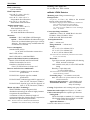
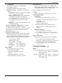
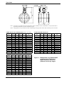
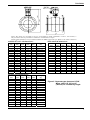
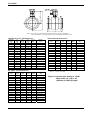
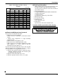
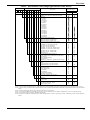
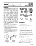
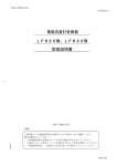
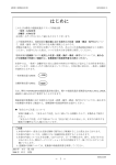
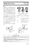
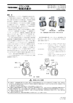
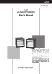
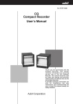
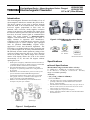
LF654 /LF620 LF654 /LF622 1/2" to 18" (15 to 450 mm) Field Intelligent Device – Mount Anywhere Series - Flanged Electromagnetic Flowmeter Introduction The electromagnetic flowmeter uses Faraday’s Law of electromagnetic induction to measure the process flow. The device consists of two units: a detector, through which the fluid to be measured flows and in which low-level signals proportional to flow rates are obtained; and a converter, which supplies excitation current to the detector, and amplifies the signals from the detector and then processes and converts the signals into the 4–20 mAdc current signal or communication signal. The meter features a Mount-Anywhere magnetic field distribution technology, the meter is highly immune to upstream flow disturbances. Combined with a multi-functional converter LF620 (combined type) or LF622 (separate type) equipped with its patented Noise-Sentry original noisesuppression circuit and advanced algorithms. The LF654 has a very high tolerance to noise, giving the unit a very stable output even for slurry fluid measurement. IR (Infrared) switches enable parameter setting of the converter without removing the cover. Flow direction can be set in either way, and its unique 128 x 128 dot matrix LCD display allows the LCD to be rotated electronically to 90, 180 and 270 degrees without opening the cover. * HART protocol (Highway Addressable Remote Transducer) is a communication protocol for industrial sensors recommended by the HCF (HART Communication Foundation). ** DevComm2000 Smart Device Communicator available through TIC for performing HART device configurations on PC or laptop. * PROFIBUS is the communications protocol for factory and process automation that the PROFIBUS Organization recommends. Instead of analog control with a conventional analog signal (4-20 mA), it is fieldbus which digitizes all signals. Flowmeters support PROFIBUS-PA. * Modbus is the communication protocol that Modicon Inc. developed. Physical layer is RS485. LF654/LF620F LF622F Figure2. LF654 Mount-Anywhere Series Flowmeters Certification No. Z01207 For PU and HR lined flowmeter Specifications Overall Specifications Measurement range in terms of flow velocity: 0 –1.0 ft/s to 0 – 39.4ft/s (0 – 0.3 m/s to 0 –12 m/s). 0 – 0.3 ft/s to 0 – 1.0 ft/s (0 – 0.1 m/s to 0 – 0.3 m/s) range is available optionally. Accuracy: < 1/2" to 18" ( 15mm to 450mm) > ±0.2 % of Rate* * * * * Combined type LF654 This pulse output error result is established under standard operating conditions at Toshiba admitted flow calibration facility. (NIST Traceable) Individual meter measurement error may vary up to ±0.5% of Rate at 1.64 ft/s (0.5m/s) or more and ±0.3% of rate ±0.039 inch/s (1mm/s) at 1.64 ft/s or less. Current output: plus ± 8µA (0.05% of span.) Refer to individual calibration data for each individual meter's measurement error. Separate type Figure1. Configuration TIC-LF654L TIC-LF654L Fluid conductivity: 3µS/cm minimum Fluid temperature: -4 to 248 °F (-20 to +120 °C): PFA lined flowmeter -4 to 140 °F (-20 to +60 °C): Polyurethane lined flowmeter 23 to 176 °F (- 5to +80 °C): Hard Rubber lined flowmeter Ambient temperature: -40 to 140 °F (-40 to +60 °C): PFA lined flowmeter -4 to 140 °F (-20 to +60 °C): PU lined and HR lined flowmeters Structure: Standard — IP 67 and NEMA 4X Watertight Option — IP68 and NEMA 6P Submersible type allows for accidental submergence up to 15m for 48 hours. This option is only available when PU or HR liners are selected. Power consumption: Standard:10W(14VA) at AC100V and Excitation current:0.2A MAX:15W (22VA) MAX:17W(24VA) with PROFIBUS Approved hazardous location certifications: Model: LF654/LF620F and LF654/LF622F cFMus Nonincendive for use in hazardous (classified) locations: Class I, II, III, Division 2, Groups A-G Detector and converter combination: LF650/LF620: Combined type for standard specification. LF650/LF622: Separate type for standard specification. LF654/LF620F: Combined type with Ex approval of Class I, II, III, Division 2 (cFMus). LF654/LF622F: Separate type with Ex approval of Class I, II, III, Division 2 (cFMus). Mount-Anywhere Technology: With TOSHIBA’s unique magnetic field distribution technology the meter is highly immune to upstream flow disturbances. A minimum of 1D (one diameter) length of upstream straight pipe from the flange is required to maintain the specification performance. Note: The test results were obtained and demonstrated at TOSHIBA's flow calibration facility, Fuchu Japan. 2 Drinking water approvals: PU and HR liner: NSF certified Model LF654 Detector Mounting style: Flange connection type Fluid pressure: -15 psi or -1.0 bar (-0.1 MPa) to the nominal pressure of the connection flange. Note: Before shipping from the manufacturer, each detector unit is tested by the following test condition. Pressure… twice of the pressure index number (ex. 300 psi in case of ASME B 16.5 class 150 flange) Time… 15 minutes Connection flange standards: ASME B16.5 class 150, ASME B16.5 class 300 EN1092-1 PN10, EN1092-1 PN16 JIS B 2220 10K, JIS B 2220 20K Principal materials: Case — carbon steel Flange material — carbon steel Linings — 1/2” to 18” (15 to 450mm): PFA 1/2” to 18” (15 to 450mm): PU 4” to 18” (100 to 450mm): HR Note: PFA liners are mechanically retained for full vacuum service (65 to 450 mm). Electrodes — Type-Super smooth, polished with self cleaning finish, and non stick shape 316L stainless steel (std.) in case of PU and HR lining Hastelloy C equivalent (std.) … in case of PFA lining Note: Electrodes are mechanically buffed and electro-chemically polished. Grounding rings — 316 stainless steel (std.) Note: See Table 4 for optional materials and other related information. Measuring tube material — 304 stainless steel Terminal box material — ADC12(Aluminum alloy die casting) Coating: Polyurethane resin coating (std.) gray colored Dimensions and weights: See Figure 3, 4, 5 and 6. Cable connection port: for separate type detectors. Cable gland — LF650: Provided as standard, G 1/2 male screws. LF654(with cFMus):Not provided, 3/4–14NPT male screws are required. Applicable diameter — 0.433 to 0.512 inch (11 to 13mm) TIC-LF654L Model LF620 and LF622 converters Input signals Analog signal — the voltage signal from detector, proportional to process flow rate (for LF622 separate type converter). Digital input DI Signal type: 20 to 30Vdc voltage signal Input resistance: 2.7k Number of inputs: one point Note: DI cannot be used with the Modbus communication. DI function — One of the following functions can be assigned to the DI signal. Range switching — Selects either the higher or lower range in the unidirectional or bidirectional 2-range setting. Totalizer control — ‘Starts and stops’ or ‘Rest and start’ the built-in totalizer. Fixed-value outputs —Outputs fixed-values for current and pulse outputs for loop check. Zero adjustment — Executes zero adjustment (on-stream at zero flow rate). Output signals Current output: 4–20mAdc (load resistance 0 to 750) Note: The current output cannot be used with the PROFIBUS-PA communication. (Refer table 6 for details) Digital outputs — Two points are available as follows. Digital output DO1: Output type: Transistor open collector Number of outputs: One point Output capacity: 30Vdc, 200mA maximum Note: DO1 cannot be used if Modbus communication connection is 3 lines. (Refer table 6 for details) Digital output DO2 : Output type: Solid-state relay output (non polarity) Number of outputs: One point Output capacity: 150Vdc, 150mA maximum or 150Vac (peak to peak), 100mA maximum Note: DO2 cannot be used with the Modbus communication. (Refer table 6 for details) DO1 and DO2 functions — One of the following functions can be assigned to DO1 and/or DO2 . • Pulse output (available only for DO1, DO2) Pulse rate: MAX 10kHz (10000pps)(DO1) MAX 100Hz (100pps)(DO2) (Over 1kpps, auto-setting) Pulse width: 0.5 to 500ms (but less than half of the period for 100% flow rate) Note: The same and simultaneous pulse is not available between DO1 and DO2.) • Multi-range selection outputs (Note 1) • High, High high, Low, and/or Low low alarm outputs (Note 2) • Empty pipe alarm output (Note 2) • Preset count output • Converter failure alarm output Note 1: Two outputs (DO1 and DO2) are needed for 4-range switching and forward/reverse 2-range switching. Note 2: Normal Open (default set) or Normal Close is selected for alarm outputs when programming. When power failure occurs, unit will be fault to Normal Open. Communications output: • HART (std.) — Digital signal is superimposed on 4–20mAdc current signal as follows: Conforms to HART protocol Load resistance: 240 to 750 Load capacitance: 0.25µF maximum Load inductance: 4mH maximum • PROFIBUS (opt.) Protocol: PROFIBUS-PA Baud rate: 31.25kbps Bus voltage: 9-30VDC Consumption electric current of bus: less than 16mA Manufacture Ident-No.: 093BHEX Standard Ident-No.: 9740HEX Slave address: 0-126 (Default address is 126) Profile: Profile Ver.3.01 for Process Control Devices Function blocks: AI(Flow)×1 , Totalizer×1 • MODBUS (opt.) Physical layer : RS485 Protocol : Modbus Mode : RTU Baudrate : 4800, 9600, 19200bps Data length : 8bit Parity bit : None, Odd, Even Stop bit : 1bit, 2bit Error check : CRC-16 Max. station number : 32(with Master device) Max. cable length : 1.2km (Note) Note: This length is specification of 3 line connection. 3 TIC-LF654L LCD display: Full dot-matrix 128×128 dot LCD display (back–light provided) A parameter change will rotate the display. Surge protection: Arresters are installed in the power supply and a current signal output circuit to help protect the meter from lightning and improve personnel safety. Parameter settings — Parameters can be set as follows: • IR Switches: Three key switches are provided to set configuration parameters. • Digital communication: HART, PROFIBUS or Modbus is needed to set parameters. • Zero adjustment: Zero point adjustment can be started by pressing the switch in the converter. • Damping: 0.1 to 60 seconds (selectable in one second increments) Case: Aluminum alloy (equal to IP 67) “Field re-verification” Mag-Prover– Toshiba’s Zero span calibration tool allows unit to be re-calibrated and verified using an internal software program (For more information contact Toshiba International Corp.) Conditions when power fails: Parameter setting values are stored in non–volatile memory and the values will be restored when the power returns to normal condition. The outputs and display will remain as follows when power fails. • Current output: 0mAdc • Digital output: OFF • LCD display: No display • HART: No communication • PROFIBUS: No communication • Modbus: No communication Power supply: One of the following can be selected: • 100 to 240Vac, 50/60Hz (allowable voltage 80 to 264Vac) 110Vdc (allowable voltage 90 to 130Vdc) • 24Vdc (allowable voltage 18 to 36Vdc) Coating: Acrylic resin-baked coating, pearl–gray colored Cable connection port: Cable glands — LF620 and LF622 without cFMus Approval: Provided as standard, outer diameter of cableφ 11~13mm Material Nylon 66 G (PF) 1/2 male threads. LF620F and LF622F with cFMus Approval: Not provided, 1/2–14NPT male threads are required. Applicable diameter — 0.433 to 0.512 inch (11 to 13mm) Note: When PROFIBUS option is specified, cable gland size is φ6〜8mm for signal cable, φ11〜13mm for power cable Vibration resistance: No resonance to the following levels of vibration: • 10 to 150Hz with acceleration of 9.8m/s2 • Vibration of 30Hz with 29.4 m/s2 in 4h in each direction will not cause any defect to unit. Note: Avoid using the flowmeter in an environment with constant vibration. Dimensions and Weights: See Figure 7 (for Separate type) MTBF: Converter: 220,000 hours (25 years) at 77 °F (25 °C) based on strict military specification MIL-HDBK-217F Detector: 350,000 hours (40 years) at 77 °F (25 °C) based on strict military specification MIL-HDBK-217F 4 TIC-LF654L Installation Dimensions Unit: inch (mm) Note1: Eye bolts are provided at the top for flowmeters sized 8" (200mm) or above, and further, a roll-prevention base is provided for flowmeters sized 10" (250mm) or larger. Note2: Cable glands are not provided for LF654 of cFMus approved type. Refer to the cable connection port at converter. JIS B 2220 10K dimensions: ASME B 16.5 class 150 dimensions: Meter size (inch) 1/2 1 1-1/4 1-1/2 2 2-1/2 3 4 5 6 8 10 12 14 16 18 L1 (inch) 5.51 6.30 7.87 6.69 7.09 7.87 9.06 9.45 9.84 10.24 11.81 13.78 15.75 17.72 19.69 21.65 L2 (inch) 8.07 8.31 8.62 8.66 9.09 9.29 9.69 10.28 10.71 11.34 12.24 13.15 14.65 14.88 15.79 16.69 L3 (inch) 9.84 10.43 10.94 11.18 12.09 12.80 13.43 14.80 15.71 16.85 19.02 21.14 24.13 25.39 27.20 29.21 No. of bolts 4 4 4 4 4 4 4 8 8 8 8 12 12 12 16 16 Weight (lbs) approx. 11.0 approx. 16..0 approx. 20.0 approx. 20.0 approx. 29.0 approx. 38.0 approx. 45..0 approx. 64.0 approx. 73.0 approx. 93.0 approx. 139.0. approx. 207.0 approx. 315.0 approx. 403.0 approx. 509.0 approx. 617.0 No. of bolts 4 4 4 4 4 4 8 8 8 8 12 12 12 16 16 20 Weight (kg) approx. 6.0 approx. 7.5 approx. 10.0 approx. 10.5 approx. 14.5 approx. 16.5 approx. 21.5 approx. 26.5 approx. 31.0 approx. 37.5 approx. 54.0 approx. 78.0 approx. 117.0 approx. 156.5 approx. 202.5 approx. 249.5 EN 1092-1 PN 16 dimensions: Meter size (mm) 15 25 32 40 50 65 80 100 125 150 200 250 300 350 400 450 L1 (mm) 140 160 200 170 180 200 230 240 250 260 300 350 400 450 500 550 L2 (mm) 203 209 217 218 232 237 255 262 273 285 310 335 365 374 397 420 L3 (mm) 251 272 285 288 310 325 347 367 399 425 475 535 588 619 677 730 Meter size (mm) 15 25 32 40 50 65 80 100 125 150 200 250 300 350 400 450 L1 (mm) 140 160 200 170 180 200 230 240 250 260 300 350 400 450 500 550 L2 (mm) 203 209 217 218 232 237 255 262 273 285 310 335 365 374 397 420 L3 (mm) 251 272 285 288 310 325 347 367 399 425 475 535 588 619 677 730 No. of bolts 4 4 4 4 4 4 8 8 8 8 12 12 16 16 16 20 Weight (kg) approx. 6.0 approx. 8.5 approx. 10.5 approx. 10.0 approx. 13.5 approx. 16.5 approx. 18.0 approx. 23.5 approx. 30.0 approx. 37.0 approx. 48.5 approx. 74.0 approx. 102.0 approx. 127.0 approx. 175.0 approx. 217.0 Note 3 : 1 inch = 25.4 mm Figure 3. LF650/LF620 and LF654/LF620F combined type flowmeters Meter Sizes 1/2" (15) to 18" (450mm) for Toshiba lay length 5 TIC-LF654L Note1: Eye bolts are provided at the top for flowmeters sized 8" (200mm) or above, and further, a roll-prevention base is provided for flowmeters sized 10" (250mm) or larger. Note2: Cable glands are not provided for LF654 of cFMus approved type. Refer to the cable connection port at converter. ASME B 16.5 class 150 dimensions: Unit: inch (mm) Meter size (inch) 1/2 1 1-1/4 1-1/2 2 2-1/2 3 4 5 6 8 10 12 14 16 18 L1 (inch) 7.90 7.90 7.90 7.90 7.90 7.90 7.90 9.80 9.80 11.80 13.80 17.70 19.70 21.70 23.60 23.60 L2 (inch) 8.07 8.31 8.62 8.66 9.09 9.29 9.69 10.28 10.71 11.34 12.24 13.15 14.65 14.88 15.79 16.69 L3 (inch) 9.84 10.43 10.94 11.18 12.09 12.80 13.43 14.80 15.71 16.85 19.02 21.14 24.13 25.39 27.20 29.21 No. of bolts 4 4 4 4 4 4 4 8 8 8 8 12 12 12 16 16 Weight (lbs) approx. 11.0 approx. 16..0 approx. 20.0 approx. 20.0 approx. 29.0 approx. 38.0 approx. 45..0 approx. 64.0 approx. 73.0 approx. 93.0 approx. 139.0. approx. 207.0 approx. 315.0 approx. 403.0 approx. 509.0 approx. 617.0 6 L1 (mm) 200 200 200 200 200 200 200 250 250 300 350 450 500 550 600 600 L2 (mm) 203 209 217 218 232 237 255 262 273 285 310 335 365 374 397 420 L3 (mm) 251 272 285 288 310 325 347 367 399 425 475 535 588 619 677 730 Meter size (mm) 15 25 32 40 50 65 80 100 125 150 200 250 300 350 400 450 L1 (mm) 200 200 200 200 200 200 200 250 250 300 350 450 500 550 600 600 L2 (mm) 203 209 217 218 232 237 255 262 273 285 310 335 365 374 397 420 L3 (mm) 251 272 285 288 310 325 347 367 399 425 475 535 588 619 677 730 No. of bolts 4 4 4 4 4 4 8 8 8 8 12 12 16 16 16 20 Weight (kg) approx. 6.5 approx. 8.5 approx. 10.5 approx. 10.5 approx. 13.5 approx. 16.5 approx. 18.0 approx. 23.5 approx. 30.0 approx. 38.0 approx. 50.0 approx. 80.0 approx. 110.5 approx. 136.0 approx. 187.5 approx. 224.5 Note 3 : 1 inch = 25.4 mm EN 1092-1 PN16 dimensions: Meter size (mm) 15 25 32 40 50 65 80 100 125 150 200 250 300 350 400 450 JIS B 2220 10K dimensions: No. of bolts 4 4 4 4 4 4 8 8 8 8 12 12 12 16 16 20 Weight (kg) approx. 6.0 approx. 7.5 approx. 10.0 approx. 10.5 approx. 15.0 approx. 17.0 approx. 21.5 approx. 26.5 approx. 31.0 approx. 38.0 approx. 55.5 approx. 83.5 approx. 125.5 approx. 166.0 approx. 215.0 approx. 257.0 Figure 4. LF650/LF620 and LF654/LF620F combined type flowmeters Meter Sizes 1/2" (15) to 18" (450mm) for ISO lay length TIC-LF654L Note1: Eye bolts are provided at the top for flowmeters sized 8”(200mm) or above, and further, a roll-prevention base is provided for flowmeters 10”(250mm) or larger. Note2: Cable glands are not provided for LF654 of cFMus approved type. Refer to the cable connection d JIS B 2220 10K dimensions: ASME B 16.5 class 150 dimensions: Meter size (inch) L1 (inch) L2 (inch) L3 (inch) No. of bolts 1/2 1 1-1/4 1-1/2 2 2-1/2 3 4 5 6 8 10 12 14 16 18 5.51 6.30 7.87 6.69 7.09 7.87 9.06 9.45 9.84 10.24 11.81 13.78 15.75 17.72 19.69 21.65 6.77 7.01 7.32 7.36 7.80 7.99 8.39 8.98 9.41 10.04 10.94 11.85 13.35 13.58 14.49 15.39 8.54 9.13 9.65 9.88 10.79 11.50 12.13 13.50 14.41 15.55 17.72 19.84 22.83 24.09 25.91 27.91 4 4 4 4 4 4 4 8 8 8 8 12 12 12 16 16 Weight (lbs) approx. 9.0 approx. 14.0 approx. 18.0 approx. 18.0 approx. 27.0 approx. 36.0 approx. 42.0 approx. 62.0 approx. 71.0 approx. 91.0 approx. 137.0 approx. 205.0 approx. 313.0 approx. 401.0 approx. 507.0 approx. 614.0 Meter size (mm) L1 (mm) (L2) (mm) L3 (mm) No. of bolts Weight (kg) 15 25 32 40 50 65 80 100 125 150 200 250 300 350 400 450 140 160 200 170 180 200 230 240 250 260 300 350 400 450 500 550 170 176 184 185 199 204 222 229 240 252 277 302 332 341 364 387 218 239 252 255 277 292 314 334 366 392 442 502 555 586 644 697 4 4 4 4 4 4 8 8 8 8 12 12 16 16 16 20 approx. 4.0 approx. 6.5 approx. 8.5 approx. 8.0 approx. 11.5 approx. 14.5 approx. 16.0 approx. 21.5 approx. 28.0 approx. 35.0 approx. 46.5 approx. 72.0 approx. 100.0 approx. 125.0 approx. 173.0 approx. 215.0 EN1092-1 PN 16 dimensions: Meter size (mm) L1 (mm) (L2) (mm) L3 (mm) No. of bolts 15 25 32 40 50 65 80 100 125 150 200 250 300 350 400 450 140 160 200 170 180 200 230 240 250 260 300 350 400 450 500 550 170 176 184 185 199 204 222 229 240 252 277 302 332 341 364 387 218 239 252 255 277 292 314 334 366 392 442 502 555 586 644 697 4 4 4 4 4 4 8 8 8 8 12 12 12 16 16 20 Weight (kg) approx. 4.0 approx. 5.5 approx. 8.0 approx. 8.5 approx. 12.5 approx. 14.5 approx. 19.5 approx. 24.5 approx. 29.0 approx. 35.5 approx. 52.0 approx. 76.0 approx. 115.0 approx. 154.5 approx. 200.5 approx. 247.5 Figure 5. Separate type detectors LF654 Meter sizes 1/2" (15) to 18" (450mm) for Toshiba lay length 7 TIC-LF654L Note1: Eye bolts are provided at the top for flowmeters sized 8" (200mm) or above, and further, a roll-prevention base is provided for flowmeters sized ASME B 16.5 class 150 dimensions: Meter size (inch) 1/2 1 1-1/4 1-1/2 2 2-1/2 3 4 5 6 8 10 12 14 16 18 L1 (inch) 7.90 7.90 7.90 7.90 7.90 7.90 7.90 9.80 9.80 11.80 13.80 17.70 19.70 21.70 23.60 23.60 JIS B 2220 10K dimensions: L2 (inch) L3 (inch) No. of bolts Weight (lbs) Meter size (mm) L1 (mm) (L2) (mm) L3 (mm) No. of bolts Weight (kg) 6.77 7.01 7.32 7.36 7.80 7.99 8.39 8.98 9.41 10.04 10.94 11.85 13.35 13.58 14.49 15.39 8.54 9.13 9.65 9.88 10.79 11.50 12.13 13.50 14.41 15.55 17.72 19.84 22.83 24.09 25.91 27.91 4 4 4 4 4 4 4 8 8 8 8 12 12 12 16 16 approx. 9.0 approx. 14.0 approx. 18.0 approx. 18.0 approx. 27.0 approx. 36.0 approx. 42.0 approx. 62.0 approx. 71.0 approx. 91.0 approx. 137.0 approx. 205.0 approx. 313.0 approx. 401.0 approx. 507.0 approx. 614.0 15 25 32 40 50 65 80 100 125 150 200 250 300 350 400 450 200 200 200 200 200 200 200 250 250 300 350 450 500 550 600 600 170 176 184 185 199 204 222 229 240 252 277 302 332 341 364 387 218 239 252 255 277 292 314 334 366 392 442 502 555 586 644 697 4 4 4 4 4 4 8 8 8 8 12 12 16 16 16 20 approx. 4.5 approx. 6.5 approx. 8.5 approx. 8.5 approx. 11.5 approx. 14.5 approx. 16.0 approx. 21.5 approx. 28.0 approx. 36.0 approx. 48.0 approx. 78.0 approx. 108.5 approx. 134.0 approx. 185.5 approx. 222.5 EN 1092-1 PN16 dimensions: Meter size (mm) L1 (mm) (L2) (mm) L3 (mm) No. of bolts 15 25 32 40 50 65 80 100 125 150 200 250 300 350 400 450 200 200 200 200 200 200 200 250 250 300 350 450 500 550 600 600 170 176 184 185 199 204 222 229 240 252 277 302 332 341 364 387 218 239 252 255 277 292 314 334 366 392 442 502 555 586 644 697 4 4 4 4 4 4 8 8 8 8 12 12 12 16 16 20 8 Weight (kg) approx. 4.0 approx. 5.5 approx. 8.0 approx. 8.5 approx. 13.0 approx. 15.0 approx. 19.5 approx. 24.5 approx. 29.0 approx. 36.0 approx. 53.5 approx. 81.5 approx. 123.5 approx. 164.0 approx. 213.0 approx. 255.0 Note 3 : 1 inch = 25.4 mm Figure 6. Separate type detectors LF654 Meter sizes 1/2" (15) to 18" (450mm) for ISO lay length TIC-LF654L ) 6 3 1 ( 5 3 . 5 ) 3 2 1 ( 4 8 . 4 ) 8 1 1 ( 0 4 . 7 ) 4 7 ( 1 9 . 2 ) 7 9 ( 2 8 . 3 ) 5 1 ( 9 5 . 0 ) 0 1 2 ( 7 2 . 8 ) 6 7 1 ( 3 9 . 6 ) 0 7 1 ( 9 6 . 6 ) 6 3 ( 2 4 . 1 Unit: inch (mm) Weight: Approx. 7 lb (3.5 kg) Note: Cable glands are not provided for LF622F cFMus approved type. Refer to the part Cable connection port at detector. Note: 1 inch = 25.4 mm Figure 7. Separate type converter LF622 and LF622F External Connections ● Combined type LF650/LF620 flowmeter and LF654/LF620F flowmeters Instrument panel : Ordered separately Grounding with 100Ω or less ground resistance Power switch (External double-pole power switch) 2 Ⅳ wire 5.5mm or more Grounding with 100Ω or less ground resistance Power supply Current output (4〜20mAdc) or PROFIBUS Digital inp ut (20〜30Vdc) or Modbus Dig ital output 2 Signal common for DI and DO Digital output 1 Grounding with 100Ω or less ground resistance NOTE: In the case of the integral type, the signal line ( A, B, G ) and the excitation line ( E, X, Y ) are the connector joints. I/O cable Powe r cable *1 Locate an external double-pole power switch on the power line near the flowmeter within easy reach of operation. Use the appropriate switch rating as shown below: Switch rating: 250Vac, 6A or more In rush current: 15A or more Figure 8. Combined type LF650/LF620 and LF654/LF620F flowmeters Wiring Diagram 9 TIC-LF654L ● Separate type LF650/LF622 flowmeter and LF654/LF622F flowmeter Instrument panel : Ordered separately Grounding with 100Ω or less ground resistance Power switch (Exte rnal double-pole power switch) Ⅳ wire 5.5mm 2 or more Grounding with 100Ω or less ground resistance Power supply or Modbus Thick walled steel conduit Signal cable (2-wire shielded hard-rubber sheathed cable) Excitation cable (3-wire shielded hard-rubber cable) Current output (4〜20mAdc) or PROFIBUS Digital input (20〜30Vdc) Digital output 2 Signal common for DI and DO Digital output 1 Grounding with 100Ω or less ground resistance I/O cable Power cable Connected detector Figure 9. Separate type LF650/LF622 and LF654/LF622F flowmeters wiring Diagram Table 1. LF620, LF620F, LF622 and LF622F Converters Signal Table Symbol L1 (+) L2 (−) GND FG DI DO1 DO2 COM Description Cable Power supply Power cable (CVV) Ground (for arrester) Frame ground Digital Input (20〜30Vdc) Digital Output 1 Digital Output 2 Signal Common for DI, DO1, DO2 I/O cable (CVV-S) + Current Output (4〜20mAdc) or PROFIBUS − Shielded cable for PROFIBUS-PA X Excitation cable Y Excitation Output (for LF622,LF622F only) E A Signal cable B Signal Input (for LF622,LF622F only) G T+ Modbus(+) Twisted-pair polyethylene TModbus(-) insulated vinyl sheath cable (JKEV,AWG24(0.2mm2)) TG Modbus(GND) Note: Symbol of the terminal is changed as follows for Modbus. DO2 → T+, DI → T-, COM → TG 10 TIC-LF654L (1) Explosion proof type flowmeters are not provided with cable glands. Refer to the part Cable connection port at detector and converter. (2) Connect the grounding wire (IV wire 5.5mm² or more) to a good earth ground (100 or less ground resistance). Make the wire as short as possible. Do not use a common ground shared with other equipment where earth current may flow. An independent earth ground is recommended. (6) The electromagnetic flowmeter is not equipped with terminating resistors. Use the terminating resistor unit for PROFIBUS-PA or junction box, if necessary. (7) Only one PROFIBUS-PA cable goes through a cable gland of the Electromagnetic Flowmeter. Please use the junction box at system configuration. (8) Install a terminator to flowmeter that connected end of Modbus network. Allowable cable length (m) Wiring Precautions (3) The allowable cable lengths between the detector and converter for the separate type flowmeter depend on the electrical conductivity of the object fluid. See Figure 10. (4) DO1, DO2 and DI use the same common terminal (COM). This COM can not be connected to other equipment which have their own ground terminal. (Power supply for connecting to DI or DO, etc…) Need to wire separately. Wiring Precautions (PROFIBUS or Modbus) (1) For wiring path, avoid places near electrical equipment that may cause electromagnetic induction or electrostatic induction interference (such as a motor, transformer and wireless transmitter). (2) Use a PROFIBUS-PA cable or a RS485 twisted-pair cable for signal cable. In addition, make sure to use a shielded cable to improve noise resistance. Installation of signal cable in metal conduit is recommended. (3) General cables are designed for indoor use where cables are not exposed to humidity, rain, etc. When you install cables, make sure to check the operating conditions such as the operating temperature range of the cable by contacting its manufacturer. (4) When you carry out cable end treatment, use a dedicated cable stripper to avoid the core wire of the cable being nicked or damaged. In addition, for cables, be careful of allowable maximum bend diameter. (Do not allow excessive twisting or bending of cables). (5) Consider installing a PROFIBUS-PA arrester in the communication path of PROFBUS-PA so that the electromagnetic flowmeter will not be affected by lightning, etc. to 300 200 100 50 30 20 10 5 3 3 5 10 20 30 50 100 200 Conductivity (S/cm) Figure 10. Electrical Conductivity and Cable Length Meter Size To select the meter size: See Table 2 and 3 to find meter sizes within the velocity of 0.3 to 39.4 ft/s (0.1 to12m/s) for a specified full-scale (measuring range high limit) flow. Select one that has its full-scale velocity between 3.0 and 10 ft/s (1 and 3m/s). Note: Make sure the full-scale flow rate used for the final planning stage stays within 39.4ft/s (12m/s) in terms of flow velocity. Table 2. Flow Rate and Flow velocity (English unit) Unit: gal/min Size (inch) 1/2' 1 1¼ 1½ 2 2½ 3 4 5 6 8 10 12 14 16 18 0.328 ft/s 0.2801 0.7781 1.275 1.992 3.112 5.260 7.967 12.45 19.45 28.01 49.80 77.81 112.0 152.5 199.2 252.1 Flow rate 0.98 ft/s 3.0ft/s 0.8403 2.561 2.334 7.115 3.824 11.66 5.975 18.21 9.337 28.46 15.78 48.09 23.90 72.85 37.35 113.8 58.35 177.9 84.03 256.1 149.4 455.3 233.4 711.5 336.1 1,025 457.5 1,394 597.5 1,821 756.3 2,305 10 ft/s 8.532 23.72 38.86 60.71 94.86 160.3 242.8 379.4 592.9 853.8 1,518 2,372 3,415 4,648 6,071 7,684 39.4 ft/s 33.61 93.37 153.0 239.0 373.5 631.2 956.1 1,494 2,334 3,361 5,975 9,337 13,445 18,300 23,902 30,251 11 TIC-LF654L Table 3. Flow Rate and Flow velocity (SI unit) Unit: m3/h Flow rate Size (mm) 15 25 32 40 50 65 80 100 125 150 200 250 300 350 400 450 0.1 m/s 0.3 m/s 1.0 m/s 0.06362 0.1767 0.2895 0.4523 0.7067 1.195 1.809 2.827 4.417 6.361 11.31 17.67 25.45 34.64 45.23 57.25 0.1908 0.5301 0.8686 1.357 2.120 3.583 5.428 8.482 13.25 19.08 33.93 53.01 76.34 103.9 135.7 171.7 0.6361 1.767 2.895 4.523 7.067 11.95 18.09 28.27 44.17 63.61 113.1 176.7 254.5 346.4 452.3 572.5 3.0 m/s 1.908 5.301 8.686 13.57 21.20 35.83 54.28 84.82 132.5 190.8 229.3 530.1 763.4 1,039 1,357 1,717 12 m/s 7.634 21.21 34.74 54.29 84.82 143.4 217.1 339.3 530.1 763.4 1,357 2,121 3,054 4,156 5,429 6,871 Ordering Information 1. When ordering the LF654 series flowmeters, refer to Tables 4 and 5 (Type Specification Codes). An entry must be made for each of the columns in each of these tables. 2. Fluid characteristics: (1) Type of fluid to be measured and its characteristics (2) Fluid temperature (3) Fluid pressure (4) Electrical conductivity of the fluid 3. Measuring range 4. I/O function setting 5. Ordering scope Flow calibration data 6. Other items Specifications other than standard items Consult a Toshiba representative when choosing materials for lining, electrodes, and grounding rings. Toshiba International Corp. (Houston) stocks Hazardous location certification type flowmeters as standard inventory. About establishment environment Do not store or install the flowmeter: • Where there is direct sunlight. • Where excessive vibration or mechanical shock occurs. • Where high temperature or high humidity conditions exist. • Where corrosive atmospheres exist. • Places that can be submerged under water. • When placing the flowmeter temporarily on the floor, support it, i.e., with a block so that the flowmeter does not topple over. In areas like the following, there may be the case that infrared switches do not function correctly. (If these are unavoidable, use an appropriate cover.) (1) Where unit (operation panel) is exposed to direct sunlight, reflection of light onto window pane and diffused light reflection. (2) Where smoke and steam may occur. (3) Where exposed to direct snow, ice or mud. 12 TIC-LF654L Table 4. Specification Code (Flange type detector LF654 Series) Model 1 2 3 4 L F 6 5 Specification Code 5 6 7 8 Description 9 10 11 12 13 14 4 D E S F G W H J U K L M N P Q R L M C D G H 1 2 5 6 Z B C D E F C N E C D E F G H Size code explanation: √ : Object Flange type electromagnetic flowmeter detector Usage cFMus Class 1 Division 2 Hazardous Location Meter size ½"(15mm) 1"(25mm) 1¼"(32mm) 1½"(40mm) 2"(50mm) 2½"(65mm) 3"(80mm) 4"(100mm) 5”(125mm) 6"(150mm) 8"(200mm) 10"(250mm) 12"(300mm) 14"(350mm) 16"(400mm) 18"(450mm) Mounting Style(Note1)(Note6) Detector/Converter combined type Detector/Converter separate type Connection flange standard, Overall length ASME B 16.5 class 150, ISO length ASME B 16.5 class 300, ISO length EN 1092-1 PN 10, ISO length EN 1092-1 PN 16, ISO length ASME B 16.5 class 150, Toshiba length ASME B 16.5 class 300, Toshiba length EN 1092-1 PN 10, Toshiba length EN 1092-1 PN 16, Toshiba length Other (Note 2) Electrode Material (Note 3)(Note 4) 316L stainless steel (Standard for PU, HR lining) Ti (titanium) Pt-Ir (platinum/iridium) Ta (tantalum) Hastelloy C (Equivalent) (Standard for PFA lining) Lining Materials (Note 3) PFA PU(Polyurethane) with NSF certified HR(Hard Rubber) with NSF certified Grounding Ring Material (Note 3)(Note 4) 316 stainless steel 316L stainless steel Ti (titanium) Ta (tantalum) Pt-Ir (platinum/iridium) Hastelloy C (Equivalent) Flow and calibration velocity range A 1.0 to 32.8 ft/s (standard range calibration) (Note 5) Excitation and Signal Cables A not provided Coating F PU coating pearl-gray colored C black tar epoxy resin : Standard : Option Detector category Gr.-A Gr.-B √ √ √ √ √ √ √ √ √ √ √ √ √ √ √ √ √ √ √ √ √ √ √ √ √ √ √ √ √ √ √ – – – – – – – –: Not available Note1: In case of LF654 with cFMus approval, Cable glands are not provided. Refer to the part of “Cable connection port” at detector and converter. Note2: Connection flange standard EN 1092-1 PN10, EN 1092-1 PN 16,JIS B 2220 10K and JIS B 2220 20K are optional for both ISO length and Toshiba length. Note3: Consult Toshiba before ordering when choosing materials at the wetting parts. Note4: In case of PU and HR lining with NSF approval, only 316/316L stainless steel are available, and Hastelloy C & Ti are undergoing testing. Note5: User specified range upon request, additional charges apply. Note6: Potting kit is available for submersible option when selecting Detector/Converter separate type with PU or HR lining. Please consult Toshiba for details. 14 TIC-LF654L Table 5. Specification Code for converters Model Specification Code Contents 1 2 3 4 5 6 7 8 9 10 11 12 13 14 L F 6 2 Electromagnetic flowmeter converter 0 Combined (Integral) type 2 Separate (Remote) type Purpose F cFMus class I, Division 2 approved Shape A Standard type with case Converter mounting fitting A None C Panel, Accessory for wall mounting (BNP material: SUS304) E Accessory for pipe installation (BNP material: SUS304) Digital input/output 2 Digital output points 2 (DO1+DO2) +Digital input point 1 (DI) Current output and Communication function(Note1) 1 Current output + HART communication 2 PROFIBUS communication 3 Current output + Modbus (RS485) communication Power supply(Note2) 100Vac-240Vac 50/60Hz, 110Vdc 24Vdc 110Vdc Instruction manual English 1 2 3 E LF620 type LF622 type – – – – Code explanation: : Standard : Option –: Not available Note 1: When PROFIBUS communication is provided, current output(4-20mA) and HART communication cannot be used. When Modbus communication is provided, digital output points 1(DO1) and digital output points (DO2), digital input point 1(DI), HART communication cannot be used. Refer to Table 6 for more details. Note2: Select 110Vdc for test report inspected under the condition of 110Vdc. Table6. Communication functions and output selection table Selection of Function Code Selected (10th digit) Communication 1 HART 2 PROFIBUS 3 Modbus Availability of outputs 4-20mAdc X DO1 (Note) DO2 X DI X Code explanation: :Available X:Not Available Note: When digital output 1 function and Modbus communication function are used at one time, TG (signal ground) of the Modbus communication function cannot be connected (2 line connection). ISO9001 and ISO14001 are certified. Misuse of this product can result in damages to property or human injury. Read related manuals carefully before using this product. 15 Specifications are subject to change without notice. Printed in Japan 2012-7 (TDOC) © TOSHIBA Corporation 2012 All Rights Reserved. http://www.toshiba.com/ind/