1
INSTRUCTION MANUAL
3 CCD CAMERA
IK-TF5
For Customer Use
Enter below the Serial No.
which is located on the
bottom of the cabinet. Retain
this information for future reference.
Model No.: IK-TF5
Serial No.:
INFORMATION
This equipment has been tested and found to comply with the limits for a Class A digital device, pursuant to Part 15 of the FCC Rules. These limits are designed to provide reasonable protection against
harmful interference when the equipment is operated in a commercial environment. This equipment
generates, uses, and can radiate radio frequency energy and, if not installed and used in accordance
with the instruction manual, may cause harmful interference to radio communications. Operation of this
equipment in a residential area is likely to cause harmful interference in which case the user will be
required to correct the interference at his own expense.
USER-INSTALLER CAUTION: Your authority to operate this FCC verified equipment could be voided if
you make changes or modifications not expressly approved by the party responsible for compliance to
Part 15 of the FCC Rules.
This Class A digital apparatus complies with Canadian ICES-003.
Cet appareil numérique de la classe A est comforme à la norme NMB-003 du Canada.
SAFETY PRECAUTIONS
Read the following safety precautions carefully before using this product. These instructions contain
valuable information on safe and proper use that will prevent harm and damage to the operator and
other persons. Make sure that you fully understand the following details (indications, graphic symbols) before proceeding to the remaining sections in this manual.
Indication definitions
Indication
Graphic symbol definitions
Symbol
Meaning
This indicates the existence of a hazard that death or catastrophic bodily
1
Warning injury* may result from improper
use.
This indicates the existence of a hazard that bodily injury*2 or property
damage*3 may result from improper
Caution
use.
Meaning
“ ” indicates a prohibited action that
must not be carried out. The actual
prohibited action is indicated in the
symbol or nearby graphically or described in text.
“ ” indicates a mandatory action
that must be carried out. The actual
instruction is indicated in the symbol or nearby graphically or described in text.
*1: Catastrophic bodily injury means loss of eyesight, burns (high and low temperatured),
shock, fracture, poisoning, etc. which leaves a sequela and require hospitalization or prolonged
treatment.
*2: Bodily injury means injuries, burns and electric shock which does not require hospitalization or
prolonged treatment.
*3: Property damage means extended harm to home, household effects, domesticated animals, and
pets.
Warning
2
•
Stop operation immediately when any abnormality or defect occurs.
Use during an abnormal condition; such as emitting smoke, burning odors, damage from
dropping invasion of foreign objects, etc. may cause fire and/or electric shock. Be always
sure to disconnect the power plug from the electrical outlet (socket) at once and contact
your dealer.
•
Avoid installing in a shower room or a bathroom.
This may cause fire and/or electric shock.
•
Do not operate in places with possibility of becoming wet.
This may cause fire and/or electric shock.
•
Do not repair, disassemble and/or modify by yourself.
This may cause fire and/or electric shock. Be always sure to contact your dealer for internal
repair, check and cleaning of the product.
•
Use the specified power supply.
Otherwise, a fire or an electric shock may occur.
•
Don’t place things or materials on the unit.
Ingress of foreign materials such as metallic things and liquid into the unit may cause a fire
or an electric shock.
•
Do not put the product in an unstable, slanting and/or vibrated place.
Drop and/or fail of the product may cause injury.
•
Do not touch the power cord or other connection cables during a thunderstorm.
This might cause electric shock.
Caution
•
Note the following instructions when installing.
• Do not put an inflammable material on the product.
• Do not put the product on an Inflammable material such as carpet or blanket.
• Do not block a vent hole.
• Do not put the product in a narrow space, since the heat generated from the product
may be difficult to emanate.
If you do not follow the above, the heat generated by the product may cause fire.
•
Do not put the product in direct sunshine and/or high temperature.
The temperature inside the product may cause fire.
•
Avoid setting in humid, smoky, vaporized or dusty places. A fire or an electric shock
may occur in such places.
This may cause fire and/or electric shock.
•
Do not point the lens directly at the sun and/or intensive light such as direct sunlight, etc.
Focusing of the light may cause injury of eye and/or fire.
•
Do not put the product in your mouth or swallow any parts.
This may cause suffocation and/or injury.
•
Ask your dealer to perform a periodical check and internal cleaning (approx. once
every five years).
Dust inside the product may cause fire and/or trouble. For check and cleaning cost, please
consult your dealer.
Disclaimer
We disclaim any responsibility and shall be held harmless for any damages or losses incurred by the
user in any of the following cases:
1. Fire, earthquake or any other act of God; acts by third parties; misuse by the user, whether intentional or accidental; use under extreme operating conditions.
2. Malfunction or non-function resulting in indirect, additional or consequential damages, including
but not limited to loss of expected income and suspension of business activities.
3. Incorrect use not in compliance with instructions in this instruction manual.
4. Malfunctions resulting from misconnection to other equipment.
5. Repairs or modifications made by the user or caused to be made by the user and carried out by
an unauthorized third party.
6. Notwithstanding the foregoing, Toshiba’s liabilities shall not, in any circumstances, exceed the
purchase price of the product.
Copyright and Right of Portrait
There may be a conflict with the Copyright Law and other laws when a customer uses, displays,
distributes, or exhibits an image picked up by a television camera without permission from the copyright holder. Please also note that transfer of an image or file covered by copyright is restricted to use
within the scope permitted by the Copyright Law.
3
TABLE OF CONTENTS
1. CAUTIONS ON USE AND INSTALLATION ..... 5
7. 3 External Sync ............................................ 22
2. COMPONENTS ................................................ 5
( 1 ) External sync signal input conditions ...... 22
( 2 ) External sync frequency range ............... 22
( 3 ) Using the unit with external sync signal .. 23
3. ITEMS CONTROLLED BY USING
ON SCREEN DISPLAY .................................... 6
4. NAMES AND FUNCTIONS .............................. 7
5. CONNECTION .................................................. 8
5. 1 Standard Connection ................................
5. 2 Cautions on Connection ...........................
5. 3 Connector Pin Assignments .....................
6. OPERATION .....................................................
8
8
8
9
6. 1 White Balance ........................................... 9
6. 2 Gain ........................................................ 10
6. 3 Shading Correction ................................. 10
7. MODE SETTING BY ON SCREEN DISPLAY ..... 11
7. 1 Using the Menues ................................... 11
7. 2 Menus ..................................................... 12
( 1 ) SHUTTER (Electronic shutter) ................ 12
(1. 1) Changing each setting in
MANU mode .....................................
(1. 2) Changing each setting in
SS (synchro. scan) mode .................
(1. 3) Changing each setting in
E.TRG mode .....................................
(1. 3. 1) Changing each setting in
1P SNR mode ...............................
(1. 3. 2) Changing each setting in
1P SR mode .................................
(1. 3. 3) Changing each setting in
PW SNR mode .............................
(1. 3. 4) Changing each setting in
PW SR mode ................................
(1. 3. 5) Changing each setting in
RR mode .......................................
( 1 ) 1P SNR (1 Pulse Sync Non Reset) ........ 24
(1. 1) 1 Pulse Trigger SYNC-NON RESET
Picture Output Timing ...................... 24
(1. 2) 1 Pulse Trigger SYNC-NON RESET
Picture Output Timing (at Time of
Internal Sync) ................................... 25
( 2 ) 1P SR (1 Pulse Sync Reset) ................... 26
(2. 1) 1 Pulse Trigger SYNC-RESET Picture
Output Timing ................................... 26
( 3 ) PW SNR (Pulse width trigger
SYNC-NON RESET) .............................. 27
(3. 1) Pulse Width Trigger SYNC-NON RESET
Picture Output Timing ...................... 27
(3. 2) Pulse Width Trigger SYNC-NON RESET
Picture Output Timing (at Time of
Internal Sync) ................................... 28
13
14
14
( 4 ) PW SR (Pulse width trigger
SYNC-RESET) ....................................... 29
15
(4. 1) 1 Pulse Width Trigger SYNC-RESET
Picture Output Timing ...................... 29
16
17
18
(2. 1) Changing each setting in GAIN ........ 18
( 3 ) WHT BAL (White balance) ...................... 19
(3. 1) Changing each setting in AWB
(Automatic White Balance) mode .... 19
(3. 2) Changing each setting in MANU
(Manual) mode ................................. 19
( 4 ) PROCESS .............................................. 20
Changing master pedestal ............... 20
Changing R pedestal ........................ 20
Changing B pedestal ........................ 20
Changing White clip .......................... 20
Changing shading correction mode ... 20
Changing manual shading correction .. 20
( 5 ) SYNC ...................................................... 21
( 5 ) RR (Reset restart) .................................. 30
(5. 1) Long Term Exposure ........................ 30
(5. 2) Input Timing Chart Example ............ 30
7. 6 Partial Read ............................................... 31
( 1 ) Partial Scanning OFF
(All pixels scanning) ................................ 31
( 2 ) Partial Scanning ON ............................... 31
( 3 ) When Partial Scanning Mode is ON ....... 31
8. INPUT OUTPUT SIGNAL SPECIFICATOINS ........ 32
(1)
(2)
(3)
(4)
(5)
(6)
HD/VD Output Amplitude Specifications ... 32
VIDEO INDEX Output Specifications ..... 32
VD Input Specifications ........................... 32
HD Input Specifications .......................... 32
Trigger Pulse Specifications .................... 32
External HD/VD Input Phase
Specifications .......................................... 32
9. CCD OUTPUT WAVEFORM TIMING CHART ... 33
( 6 ) OPTION .................................................. 21
( 1 ) Horizontal Output Waveform Timing Chart ... 33
( 2 ) Vertical Output Waveform Timing Chart ... 33
10. SPECIFICATIONS ....................................... 34
(6. 1) Changing RS232C communication
baud rate .......................................... 21
11. EXTERNAL APPEARANCE DIAGRAM ...... 35
( 7 ) Setting to factory setting status ............... 22
12. BEFORE MAKING A SERVICE CALL ........ 35
(5. 1) Adjusting horizontal phase ............... 21
(5. 2) Changing RGB SYNC ...................... 21
4
( 1 ) Setting by 1H .......................................... 23
( 2 ) Setting by the frame ................................ 23
7. 5 EXT TRIG (External trigger) ..................... 24
12
( 2 ) GAIN (Video gain) ................................... 18
(4. 1)
(4. 2)
(4. 3)
(4. 4)
(4. 5)
(4. 6)
(3. 1) H (horizontal) phase adjustment ...... 23
( 4 ) Changing HD/VD input/output ................ 23
7. 4 Synchro. Scan Operatin ........................... 23
1. CAUTIONS ON USE AND INSTALLATION
•
Carefully handle the units.
•
Do not drop, or give a strong shock or vibration to
the camera. This may cause problems. Treat the
camera cables carefully to prevent cable problems,
such as cable breakdown and loosened connections.
•
Do not shoot intense light.
If there is an intense light at a location on the
screen such as a spot light, a blooming and smearing may occur. When intense light enters, vertical
stripes may appear on the screen. This is not a
malfunction. Ghosts may occur when there is an
intense light near the object. In this case, change
the shooting angle.
•
•
•
Keep the protection cap away from children. Children may put them into mouth or swallow them
accidentally. The protection cap protects the image sensing plane when the lens is removed from
the camera, do not throw away.
•
When not using the camera for a longtime.
Stop supplying power.
•
When cleaning the camera.
Always turn off the power and clean with a piece
of soft dry cloth. Do not use benzine, alcohol, thinner, household detergents, chemically treated
cloths, etc. If used, coating and printed letters may
be discolored. When cleaning the lens, use a lens
cleaning paper, etc.
Install the camera in a location free from noise.
If the camera or the cables are located near power
utility lines or a TV, etc. undesirable noise may appear on the screen. In such a case, try to change
the location of the camera or the cable wiring.
Handling of the protection cap.
•
Avoid using or storing the camera in the following places:
Places filled with highly flammable gas.
Moire
Places near gasoline, benzene, or paint thinner.
When thin stripe patterns are shot, stripe patterns
that are not actually there (moire) may appears
as interference stripes. This is not a malfunction.
Places subject to strong vibration.
Operating ambient temperature and humidity.
Do not use the camera in places where temperature and humidity exceed the specifications. Picture quality will lower and internal parts may be
damaged.
Be particularly careful when using in places exposed to direct sunlight. When shooting in hot
places, depending on the conditions of the object
and the camera (for example when the gain is increased), noise in the form of vertical strips or
white dots may occur. This is not a malfunction.
Places contacting chemicals (such as pesticides),
rubber or vinyl products for a long period of time.
•
For the customers in Europe.
WARNING
This is a Class A product. In a domestic environment this product may cause radio interference in
which case the user may be required to take adequate measures. The cable used to connect to
the VIDEO OUT DC IN/SYNC plug should be less
than 30m in length.
2. COMPONENTS
(1) Camera Control Unit ...................................................................................................................... 1
(2) Accessories
(a) Instruction manual ................................................................................................................... 1
5
3. ITEMS CONTROLLED BY USING ON SCREEN DISPLAY
Item
MODE
E. TRG
MANU speed
Electronic shutter
Gain
White
balance
Process
Sync Option
6
Available selectins
MANU, SS, E. TRG
1P SNR, 1P SR, PW SNR, PW SR, RR
OFF, 1/100s, 1/250s, 1/500s, 1/1000s, 1/2000s,
1/4000s, 1/10000s, 1/25000s, 1/50000s, 1/1000000s
Syncro. Partial read OFF 1/525H~524/525H, OFF, 1FRM~512FRM
scan.
Partial read ON 1/175H~174/175H, OFF, 2FRM~512FRM
Partial read
OFF, ON (180 fps)
Trigger
,
(1P SNR/SR)
Trigger
,
(PW SNR/SR)
1P
0.01ms~16ms
exposure time
MODE
MANU, OFF
MANU
-3dB~18dB
MODE
AWB, MANU
Color temperature
3200K, 5600K
MANUAL R GAIN
-100~0~100
MANUAL B GAIN
-100~0~100
Master pedestal
-64~0~64
R pedestal
-64~0~64
B pedestal
-64~0~64
White clip
-50~0~50
Shading correction
MANU, OFF
mode
Manual shading
-128~0~127
correction
H phase adjustment
-100~0~100
RGB SYNC
G, ALL ON, ALL OFF
Baud rate
9600 bps, 19200 bps
Preset value
(Factory setting)
MANU
1P SNR
OFF
OFF
OFF
16 ms
OFF
0dB
AWB
3200K
0
0
0
0
0
0
MANU
0
0
G
9600 bps
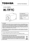
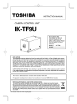
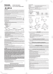
4. NAMES AND FUNCTIONS
8 DC IN 12V terminal
1 Prism faceplate
2 DISP button
4 MENU UP button
(AWB)
6 DATA UP (AWB) button
DISP
MENU DATA
DC IN 12V
PAGE
7 DATA DOWN button
RGB
5 MENU DOWN button
9 RGB terminal
3 PAGE button
[ Front ]
1 Prism faceplate
2 DISP button
3 PAGE button
[ Rear ]
The protection cap is attached on the lens mount portion. After removing the cap,
mount the lens. Be careful not to scratch or touch the optical area.
Used when switching the display.
Used when switching to the menu and when selecting the menus.
4 MENU UP button
Select the function to be confirmed or changed on the menu.
5 MENU DOWN button
6 DATA UP (AWB) button
Select the function to be confirmed or changed on the menu.
7 DATA DOWN button
8 DC IN 12V terminal
9 RGB terminal
Changes the value of the function selected by the MENU (UP/DOWN) button. (Also
used when using AWB.)
Changes the value of the function selected by the MENU (UP/DOWN) button.
Accept a DC power input (12V).
Used as the connector terminal for RGB output, and SYNC output.
HD and VD signals are input/output. When the random trigger operation is used,
the trigger signal is input and the index signal is output. This terminal also includes
an RS232C format control.
7
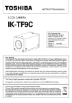
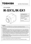
5. CONNECTION
5. 1 Standard Connection
Lens
Camera cable
(option)
RGB
IK-TF5
DC IN 12V
Less than 4 mm
DC power supply
Image processing
equipments, etc.
5. 2 Cautions on Connection
• When connecting the camera cables, be sure to turn off the camera and the other equipment connected.
• We suggest using a C mount lens made for a 3CCD camera.
When using another lens, the best camera performance of this camera may not be obtained.
(For example, low resolution may occur, focus may be lost through the range of a zoom lens, and
flare, ghost or shading may occur)
Furthermore, in order to avoid damaging the mounting portion of the camera head, use a lens which
has projection dimension from the mounting base of less than 0.157"(4mm).
• For DC power supply connecting to DC IN 12V terminal, use UL listed and/or CSA approved ungrounding
type AC adaptor with the specifications described below.
Power supply voltage
: DC12V±10%
Current rating
: More than 830 mA, Less than2.5A
Ripple voltage
: Less than 50 mV(p–p)
Connector
: HR10A–7P–4S by HIROSE electronics Co. Ltd
Pins 1, 2 : 12V
Pins 3, 4 : GND
5. 3 Connector Pin Assignments
DC IN 12V
1
2
3
4
8
+12V
+12V
GND
GND
RGB
1
3
2
4
1
2
3
4
5
6
7
8
9
10
11
12
13
14
15
R
G
B
TXD
GND
GND
GND
SYNC
12V
GND
RXD
TRIG
HD IN/OUT
VD IN/OUT
INDEX
4
5
10
15
14
2
3
8
9
13
1
6
7
12
11
6. OPERATION
1 Referring to the item " 5. CONNECTION", connect each equipment correctly.
2 Turn on the connected equipment and the camera.
3 Pointing the lens at the object, operate the lens iris adjustment, focus adjustment, etc..
4 Referring to the item "6.1 White Balance", operate the adjustment.
5 Referring to the items "6.2 Gain, 7. MODE SETTING BY ON SCREEN DISPLAY", select the necessary
items.
6. 1 White Balance
For the white balance adjustment for this unit, AWB (Automatic White Balance) and MANU (Manual white
balance) adjustments are provided. Referring to the items "7.2 (3) WHT BAL (White balance), 7. MODE SETTING BY ON SCREEN DISPLAY", select the desired mode.
Outline
Notes
AWB
(Automatic White Balance)
Adjust white balance by displaying the
white object inside the area set by AWB
menu and pressing the [DATA UP] button.
When the shutter mode is EXT TRIG,
AWB is not available.
MANU
(Manual White Balance)
Adjust the white balance manually using
the WHT BAL menu while shooting the
white object.
Adjustment is performed by confirming
with a waveform monitor.
1 AWB (Automatic white balance)
• Set the MODE to AWB on the WHT BAL menu.
Perform the C.TEMP (color temperature conversion) setting, if necessary.
(Refer to the item "7.2 (3) WHT BAL (White balance)".)
3200K : Appropriate for indoor shooting.
5600K : Appropriate for outdoor shooting.
• If the index menu/menu is displayed, press the [DISP] button to disable the color bar pattern or the
character display on the menu.
• Shoot a known white object that fills the screen and push [DATA UP] button for approx. 1 second.
• The character AWB blinks on the screen when the AWB starts.
• The character AWB stops blinking when the AWB finishes, and the result is displayed for approx. 1
second.
Result displayed
AWB OK
AWB NG LEVEL
LOW
AWB NG
LEVEL HIGH
AWB NG
C. TEMP HIGH
AWB NG
C. TEMP HIGH
Meaning
Automatic white balance adjustment finished correctly.
Automatic white balance adjustment cannot be performed because the
video level is too low.
Set the video level properly.
Automatic white balance adjustment cannot be performed because the
video level is too high.
Set the video level properly.
Automatic white balance adjustment cannot be performed because the
color temperature is too low.
If the C.TEMP is set to 5600K, set to 3200K.
If the message appears with the C.TEMP set to 3200K, change the
illumination or use a color temperature conversion filter.
Automatic white balance adjustment cannot be performed because the
color temperature is too high.
If the C.TEMP is set to 3200K, set to 5600K.
If the message appears with the C.TEMP set to 5600K, change the
illumination or use the color temperature conversion filter.
9
Result displayed
AWB NG
NOT AVAILABLE
AWB NG
Meaning
Automatic white balance adjustment cannot be performed because the
shutter speed mode is EXT TRIG mode.
Automatic white balance adjustment cannot be performed for other
reasons. Such as no white area is included in an object, etc.
2 MANU (Manual white balance)
• Set the MODE to MANUAL on the WHT BAL menu.
(Refer to the item "7.2 (3) WHT BAL (white balance)".)
• Shoot a known white object, adjust the white balance adjusting the levels of R GAIN and B GAIN on the
menu, confirming with a monitor or a waveform monitor.
(Refer to the item "7.2 (3) (3.2) Changing each setting in MANU mode".)
6. 2 Gain
When the image is dark even if the lens iris is open, change the gain (video gain) to get the proper video level.
For the gain adjustment of the unit, MANUAL (Manual) and OFF (0 dB) modes are provided. Select the mode
on the GAIN menu. (Refer to the item "7.2 (2) GAIN (Video gain)".)
1 MANU (Manual gain)
Gain adjustment is performed on the GAIN menu. The adjustment range is from -3dB to 18dB in 1dB steps.
(Refer to the item "7.2 (2) (2.1) (a) Changing the gain in MANUAL mode".)
2 OFF
Gain is fixed at 0 dB.
6. 3 Shading Correction
Due to the lens used or the environmental condition, vertical color shading may occur at the top and bottom of
the screen. In this case, the shading correction can decrease the color shading. For the shading correction of
the unit, MANU (Manual shading correction) and OFF (no shading correction) modes are provided. Select the
mode on the PROCESS menu. (Refer to the item "7.2 (4) (4.5) Changing shading correction mode".)
1 MANU (Manual Shading)
Perform the correction amount setting on the PROCESS menu, confirming with a monitor or a waveform
monitor. (Refer to the "7.2 (4) (4.6) Changing the manual shading correction setting".)
2 OFF
The status is no shading correction.
* The shading correction is effective when the lens iris or zoom ratio is fixed. Use the unit with SHADING OFF for variable lens conditions.
10
7. MODE SETTING BY ON SCREEN DISPLAY
Various settings can be controlled on the unit by using the on screen menu displayed on the monitor. The
contents once set are memorized when the power is turned off, so it is unnecessary to set again when using
the unit next time. When the setting is performed, select the menu of the item to be set.
7. 1 Using the Menus
When the power turns on, the normal screen showing only the video signal appears. Change the output to
each screen (video signal output, Index menu, and menus) by using the [DISP], [PAGE], [MENU UP], and
[MENU DOWN] buttons.
* A menu is selected when pushing the [PAGE] button after moving the "→" on the screen by the [MENU UP],
[MENU DOWN] button while the Index menu is displayed.
POWER ON
Video signal output
Index menu
DISP
DISP
DISP
PAGE
PAGE
Menues
PAGE
SHUTTER
MANU
SS
WHT BAL
GAIN
PAGE
MANU
OFF
PAGE
AWB
MANU
PROCESS
SHAD. PAGE
PAGE
MANU
SHAD.
OFF
SYNC
INT
OPTION
PAGE
BAUD
RATE
EXT
E. TRG
1P SR
E. TRG
1P SNR
E. TRG
PW SR
E. TRG
PW SNR
E. TRG
RR
11
7. 2 Menus
• Select the menu to change the setting by referring the item "7.1 Using the Menues".)
• When the [MENU UP], [MENU DOWN] buttons are pushed, the "→" on the screen moves up and down. Move
the "→" to the item to change.
( 1 ) SHUTTER (Electronic shutter)
The electronic shutter has three modes; MANU (Manual), SS (Synchro. Scan), EXT TRIG (External trigger).
Set the "→" to "MODE" and push [DATA UP], {DATA DOWN] button to select the desired mode among "MANU",
"SS", "EXT TRIG".
(1. 1) Changing each setting in MANU mode
Move up down
By pushing
MENU UP, DOWN
Set by pushing
DATA UP, DOWN
• Shutter mode MANU, SS, E.TRG
-- SHUTTER -MODE
MANU
PART
MANU
50000
OFF
• Shutter speed setting
OFF, 100 (1/100s), 250 (1/250s), 500 (1/500s)
1000 (1/1000s), 2000 (1/2000s), 4000 (1/4000s)
10000 (1/10000s), 25000 (1/25000s)
50000 (1/50000s)100000 (1/100000s)
*100 (1/100s) may not be specified at PART
(Partial read) ON setting.
• Partial read switch OFF/ON
<MODE = MANUAL>
(a) Changing the shutter speed
1 Set the "→" to MANU by pushing [MENU UP], [MENU DOWN] buttons.
2 Set the shutter speed by pushing [DATA UP], [DATA DOWN] buttons.
(b) Partial read setting
1 Set the "→" to PART by pushing [MENU UP], [MENU DOWN] buttons.
2 Select either OFF or ON by pushing [DATA UP], [DATA DOWN] buttons.
12
(1. 2) Changing each setting in SS (synchro. scan) mode
Move up down
By pushing
MENU UP, DOWN
Set by pushing
DATA UP, DOWN
• Shutter mode MANU, SS, E.TRG
-- SHUTTER -MODE
SS
PART
SS
OFF
OFF
• Synchro. scan setting
OFF : 1/525H↔524/525H↔OFF↔1FRM↔512FRM
ON : 1/175H↔174/175H↔OFF↔1FRM↔512FRM
• Partial read switch
OFF/ON
<MODE = SS>
(a) Changing the shutter speed setting
1 Set the "→" to SS by pushing [MENU UP], [MENU DOWN] buttons.
2 Select the shutter speed by pushing [DATA UP], [DATA DOWN] buttons.
(b) Partial read setting
1 Set the "→" to PART by pushing [MENU UP], [MENU DOWN] buttons.
2 Select either OFF or ON by pushing [DATA UP], [DATA DOWN] buttons.
Note:
The longer the storage time with extended exposures, the more visible certain characteristics of CCD
cameras become: fixed pattern noise, white pixels, etc.
13
(1. 3) Changing each setting in E.TRG mode
The E.TRG has five modes; 1P SNR, 1P SR, PW SNR, PW SR, RR.
First set the "→" to MODE and select E. TRG, then set the "→" to E.TRG and select the desired E.TRG mode.
(1. 3. 1) Changing each setting in 1P SNR mode
Move up down
By pushing
MENU UP, DOWN
Set by pushing
DATA UP, DOWN
• Shutter mode MANU, SS, E.TRG
-- SHUTTER -MODE
E.TRG
TRG.P
EXP.
PART
E.TRG
1P SNR
16ms
OFF
• E.TRG mode
1P SNR, 1P SR, PW SNR, PW SR, RR
• Input trigger pulse setting at 1P SNR and 1P SR
Input trigger pulse : positive polarity
Input trigger pulse : negative polarity
• Exposure time setting at 1P SNR and 1P SR
0.02 ms
0.4 ms
1 ms
16 ms
0.02 ms step
0.1 ms step 1 ms step
• Partial read switch OFF/ON
<MODE = E.TRG E.TRG = 1P SNR>
(a) Changing the polarity of inputting trigger pulse setting
1 Set the "→" to TRG.P by pushing [MENU UP], [MENU DOWN] buttons.
,
by pushing [DATA UP], [DATA DOWN] buttons.
2 Select either
(b) Changing 1P SNR exposure time setting
1 Set the "→" to EXP. by pushing [MENU UP], [MENU DOWN] buttons.
2 Set the exposure time by pushing [DATA UP], [DATA DOWN] buttons.
Note:
The longer the storage time with extended exposures, the more visible certain characteristics of CCD
cameras become: fixed pattern noise, white pixels, etc.
(c) Changing the partial read setting
1 Set the "→" to PART by pushing [MENU UP], [MENU DOWN] buttons.
2 Select either OFF or ON by pushing [DATA UP], [DATA DOWN] buttons.
14
(1. 3. 2) Changing each setting in 1P SR mode
Move up down
By pushing
MENU UP, DOWN
Set by pushing
DATA UP, DOWN
• Shutter mode MANU, SS, E.TRG
-- SHUTTER -MODE
E.TRG
TRG.P
EXP.
PART
E.TRG
1P SR
16ms
OFF
• E.TRG mode
1P SNR, 1P SR, PW SNR, PW SR, RR
• Input trigger pulse setting at 1P SNR and 1P SR
Input trigger pulse : positive polarity
Input trigger pulse : negative polarity
• Exposure time setting at 1P SNR and 1P SR
0.02 ms
0.4 ms
1 ms
16 ms
0.02 ms step
0.1 ms step 1 ms step
• Partial read switch OFF/ON
<MODE = E.TRG E.TRG = 1P SR>
(a) Changing the polarity of inputting trigger pulse setting
1 Set the "→" to TRG.P by pushing [MENU UP], [MENU DOWN] buttons.
,
by pushing [DATA UP], [DATA DOWN] buttons.
2 Select either
(b) Changing 1P SR exposure time setting
1 Set the "→" to EXP. by pushing [MENU UP], [MENU DOWN] buttons.
2 Set the exposure time by pushing [DATA UP], [DATA DOWN] buttons.
Note:
The longer the storage time with extended exposures, the more visible certain characteristics of CCD
cameras become: fixed pattern noise, white pixels, etc.
(c) Changing the partial read setting
1 Set the "→" to PART by pushing [MENU UP], [MENU DOWN] buttons.
2 Select either OFF or ON by pushing [DATA UP], [DATA DOWN] buttons.
15
(1. 3. 3) Changing each setting in PW SNR mode
Move up down
By pushing
MENU UP, DOWN
Set by pushing
DATA UP, DOWN
• Shutter mode MANU, SS, E.TRG
-- SHUTTER -MODE
E.TRG
TRG.P
PART
E.TRG
PW SNR
OFF
• E.TRG mode
1P SNR, 1P SR, PW SNR, PW SR, RR
• Input trigger pulse setting at PW SNR and PW SR
Input trigger pulse : positive polarity
Input trigger pulse : negative polarity
• Partial read switch OFF/ON
<MODE = E.TRG E.TRG = PW SNR>
(a) Changing the polarity of inputting trigger pulse setting
1 Set the "→" to TRG.P by pushing [MENU UP], [MENU DOWN] buttons.
,
by pushing [DATA UP], [DATA DOWN] buttons.
2 Select either
(b) Changing the partial read setting
1 Set the "→" to PART by pushing [MENU UP], [MENU DOWN] buttons.
2 Select either OFF or ON by pushing [DATA UP], [DATA DOWN] buttons.
Note:
The longer the storage time with extended exposures, the more visible certain characteristics of CCD
cameras become: fixed pattern noise, white pixels, etc.
16
(1. 3. 4) Changing each setting in PW SR mode
Move up down
By pushing
MENU UP, DOWN
Set by pushing
DATA UP, DOWN
• Shutter mode MANU, SS, E.TRG
-- SHUTTER -MODE
E.TRG
TRG.P
PART
E.TRG
PW SR
OFF
• E.TRG mode
1P SNR, 1P SR, PW SNR, PW SR, RR
• Input trigger pulse setting at PW SNR and PW SR
Input trigger pulse : positive polarity
Input trigger pulse : negative polarity
• Partial read switch OFF/ON
<MODE = E.TRG E.TRG = PW SR>
(a) Changing the polarity of inputting trigger pulse setting
1 Set the "→" to TRG.P by pushing [MENU UP], [MENU DOWN] buttons.
,
by pushing [DATA UP], [DATA DOWN] buttons.
2 Select either
Note:
The longer the storage time with extended exposures, the more visible certain characteristics of CCD
cameras become: fixed pattern noise, white pixels, etc.
17
(1. 3. 5) Changing each setting in RR mode
Move up down
By pushing
MENU UP, DOWN
Set by pushing
DATA UP, DOWN
• Shutter mode MANU, SS, E.TRG
-- SHUTTER -MODE
E.TRG
PART
E.TRG
RR
OFF
• E.TRG mode
1P SNR, 1P SR, PW SNR, PW SR, RR
• Partial read switch OFF/ON
<MODE = E.TRG E.TRG = SS>
(a) Changing the partial read setting
1 Set the "→" to PART by pushing [MENU UP], [MENU DOWN] buttons.
2 Select either OFF or ON by pushing [DATA UP], [DATA DOWN] buttons.
Note:
The longer the storage time with extended exposures, the more visible certain characteristics of CCD
cameras become: fixed pattern noise, white pixels, etc.
( 2 ) GAIN (Video gain)
GAIN has two modes; MANU, OFF.
Set the "→" to MODE, push the [DATA UP], [DATA DOWN], and select mode among MANU, OFF. In the OFF
mode, gain is fixed to 0dB.
(2. 1) Changing each setting in GAIN
Move up down
By pushing
MENU UP, DOWN
Set by pushing
DATA UP, DOWN
-- GAIN -MODE
MANU
MANU
0dB
• Gain mode MANU, OFF
• Manual gain -3 dB to 18 dB (10 dB step)
(a) Changing the gain in MANU mode
1 Set the "→" to MANU by pushing [MENU UP], [MENU DOWN] buttons.
2 Set the manual gain by pushing [DATA UP], [DATA DOWN] buttons.
18
( 3 ) WHT BAL (White balance)
WHT BAL has two modes; AWB, MANU.
Set the "→" to MODE, push the [DATA UP], [DATA DOWN], and select mode among AWB, MANU.
(3. 1) Changing each setting in AWB (Automatic White Balance) mode
Move up down
By pushing
MENU UP, DOWN
Set by pushing
DATA UP, DOWN
-- WHT BAL -MODE
C.TEMP
AWB
3200
• White balance mode setting (AWB, MANU)
• Color temperature setting 3200, 5600
(a) Changing color temperature setting
1 Set the "→" to C.TEMP by pushing [MENU UP], [MENU DOWN] buttons.
2 Select either 3200 or 5600 by pushing [DATA UP], [DATA DOWN] buttons.
(3. 2) Changing each setting in MANU (Manual) mode
Move up down
By pushing
MENU UP, DOWN
Set by pushing
DATA UP, DOWN
-- WHT BAL -MODE
R GAIN
B GAIN
C. TEMP
MANU
0
0
3200
• White balance mode AWB, MANU
• Red gain adjustment -100 to 100
• Blue gain adjustment -100 to 100
• Color temperature setting 3200, 5600
(a) Changing the red gain
1 Set the "→" to R GAIN by pushing [MENU UP], [MENU DOWN] buttons.
2 Set the red gain by pushing [DATA UP], [DATA DOWN] buttons.
(b) Changing the blue gain
1 Set the "→" to B GAIN by pushing [MENU UP], [MENU DOWN] buttons.
2 Set the blue gain by pushing [DATA UP], [DATA DOWN] buttons.
19
( 4 ) PROCESS
Move up down
By pushing
MENU UP, DOWN
Set by pushing
DATA UP, DOWN
-- PROCESS -MODE
R.PED
B.PED
W.CLP
SHAD.
MANU
• Master pedestal adjustment -64 to 64
0
0
0
0
MANU
0
• R pedestal adjustment -64 to 64
• B pedestal adjustment -64 to 64
• White clip adjustment -50 to 50
• Shading mode setting MANU/OFF
• Manual shading adjustment -100 to 100
(4. 1) Changing master pedestal
1 Set the "→" to M. PED by pushing [MENU UP], [MENU DOWN] buttons.
2 Set the master pedestal by pushing [DATA UP], [DATA DOWN] buttons.
(4. 2) Changing R pedestal
1 Set the "→" to R. PED by pushing [MENU UP], [MENU DOWN] buttons.
2 Set the R pedestal by pushing [DATA UP], [DATA DOWN] buttons.
(4. 3) Changing B pedestal
1 Set the "→" to B. PED by pushing [MENU UP], [MENU DOWN] buttons.
2 Set the B pedestal by pushing [DATA UP], [DATA DOWN] buttons.
(4. 4) Changing White clip
1 Set the "→" to W. CLP by pushing [MENU UP], [MENU DOWN] buttons.
2 Set the W. CLP by pushing [DATA UP], [DATA DOWN] buttons.
Note: The alignment value for shading is fixed to "0" when selecting SHAD. OFF. MANU is not displayed in the menu.
(4. 5) Changing shading correction mode
1 Set the "→" to SHAD. by pushing [MENU UP], [MENU DOWN] buttons.
2 Set the SHAD. by pushing [DATA UP], [DATA DOWN] buttons.
(4. 6) Changing manual shading correction
1 Set the "→" to MANU by pushing [MENU UP], [MENU DOWN] buttons.
2 Set the MANUAL SHADING by pushing [DATA UP], [DATA DOWN] buttons.
20
( 5 ) SYNC
When an external sync signal is input, the display changes from INT (internal sync) to EXT (external sync)
automatically.
Move up down
By pushing
MENU UP, DOWN
Set by pushing
DATA UP, DOWN
-- SYNC -MODE
H PHASE
RGB SYNC
EXT
0
G
• Sync system display
• H PHASE -100 to 100
• RGB SYNC G, ALL ON, ALL OFF
(5. 1) Adjusting horizontal phase
1 Set the "→" to H PHASE by pushing [MENU UP], [MENU DOWN] buttons.
2 Adjust the horizontal phase by pushing [DATA UP], [DATA DOWN] buttons.
(5. 2) Changing RGB SYNC
1 Set the "→" to RGB SYNC by pushing [MENU UP], [MENU DOWN] buttons.
2 Select G, ALL ON or ALL OFF by pushing [DATA UP], [DATA DOWN] buttons.
( 6 ) OPTION
Move up down
By pushing
MENU UP, DOWN
Set by pushing
DATA UP, DOWN
-- OPTION -BAUD RATE
9600
• RS232C baud rate 9600, 19200
(6. 1) Changing RS232C communication baud rate
1 Set the "→" to BAUD RATE by pushing [MENU UP], [MENU DOWN] buttons.
2 Select either 9600 or 19200 by pushing [DATA UP], [DATA DOWN] buttons.
21
( 7 ) Setting to factory setting status
The contents set of each scene file can be returned to the factory default status (preset status).
(1) If characters are displayed on the screen, press the [DISP] button to disable the character display.
(2) Push [MENU DOWN] and [DATA DOWN] buttons simultaneously for approx. 1 second.
(3) The preset operation starts. When the preset operation finishes, the character PRESET OK is displayed
for approx. 1 second.
7. 3 External Sync
When using the unit with an external sync signal, input HD and VD to RGB terminal on the rear panel, or input
SYNC to RGB terminal. When the external sync signal is input, the camera automatically switches its sync
from the internal sync to the external sync.
The operation is as shown below, depending on the unit's status and how external sync signals are input.
Shutter mode
At time of SYNC-NON
RESET mode
HD input VD input
N
N
Y
Y
N
Y
Y
N
At time of SYNC-RESET
mode
At time of reset restart
At time of manual
shutter
N
*
Y
*
Y
Y
N
Y
*
N
N
Y
Y
N
N
Y
N
Y
Note
Internal sync mode
External sync mode
Only V reset is applied due to VD input. Normally not used.
HD is synchronized to external, but video is not output
because there is no VD input. Normally not used.
Internal sync mode. The presence of VD is ignored, and after
a specified time after a trigger input, V reset is applied.
HD is synchronized to external. The presence of VD is
ignored, and after a specified time after a trigger input, V
reset is applied.
HD is synchronized to external. Video is output due to VD
input.
HD is synchronized to the inside of the camera. Video is
output due to VD input.
Video is not output because there is no VD input. Normally
not used.
Internal sync mode
External sync mode
HD is synchronized to external. Normally not used.
Disabled
* Either Y or N is permitted.
( 1 ) External sync signal input conditions
HD: 2 to 5V(p-p) Negative
VD: 2 to 5V(p-p) Negative
( 2 ) External sync frequency range
(External sync with HD, VD)
For EIA standard frequency : Within ±1% (at horizontal sync frequency of 31.469 kHz)
22
( 3 ) Using the unit with external sync signal
When adjusting H (horizontal) phase refer to the item "7.2 (5) (5.1) Adjusting horizontal phase".
External
Sync. signal
(3. 1) H (horizontal) phase adjustment
Observe the external sync signal and the video signal output
waveform of the unit with a dual trace oscilloscope, and adjust H phase so that the H phases match.
Match
the phase.
Camera
Video output
( 4 ) Changing HD/VD input/output
(1) Put off 6 screws both on flank/top of camera chassis.
(2) Change internal switch SJ01(HD/VD).
SJ01
HD/VD OUTPUT
HD/VD INPUT high-impedance
HD/VD INPUT 75Ω (factory setting)
7. 4 Synchro. Scan Operation
The shutter speed can be set by the horizontal scanning period (1H) or by the frame.
( 1 ) Setting by 1H
1/525H to 524/525H stands for the setting by the 1H and the shutter speed can be set by the 1H (31.8 ms).
( 2 ) Setting by the frame
1FRM to 512FRM stand for the setting (long period exposure) by the frame.
The video signal stored during the frame period set is output as 1 frame video image at a frame interval
specified.
VD output
Video output
Index output
(INDEX)
n
n+1
(4FRM setting)
23
7. 5 EXT TRIG (External trigger)
Charge begins to accumulate after the trigger input, and 1 frame images are output. There are five modes: 1P
SNR, 1P SR, PW SNR, PW SR, RR.
The RGB terminal trigger input and index output interface are as shown below.
5V
15kΩ
1SS357
150Ω
Trigger input
(CMOS out)
INDEX out
( 1 ) 1P SNR (1 Pulse Sync Non Reset)
Charge begins to accumulate after the trigger input to the RGB terminal, and 1 field images are output.
(1. 1) 1 Pulse Trigger SYNC-NON RESET Picture Output Timing
(At Time of One-shot or Continuous External VD/Continuous External HD Input)
Negative polarity mode
Trigger*1
Positive polarity mode
About 1 µs
Exposure period*2
Exposure period*2
External HD IN*1
External VD IN*1
About 1H
(Internal VD)
VIDEO INDEX
Video output
525H (Partial scanning OFF)
175H (Partial scanning ON)
The internal VD falling edge is within the exposure
period and thus video is not output. *3
*1: Externally input signal
*2: Exposure time is determined by the setting of "(1.3) Changing each setting in E.TRG mode".
*3: Video is output at the falling edge of the internal VD following completion of the exposure period.
The video and the VIDEO INDEX have a paired relationship.
Note:
When the next trigger is input before completion of the output of the video corresponding to the trigger, there will be an effect on the video.
24
(1. 2) 1 Pulse Trigger SYNC-NON RESET Picture Output Timing (at Time of Internal Sync)
Negative polarity mode
Trigger*1
Positive polarity mode
About 1 µs
Exposure period*2
Exposure period*2
VD OUT*3
VIDEO INDEX
Video output
525H (Partial scanning OFF)
175H (Partial scanning ON)
*1: Externally input signal
*2: Exposure time is determined by the setting of "(1.3) Changing each setting in E.TRG mode".
As long as there is no external sync input, the internal VD will be output when the rear panel HD/VD signal
input/output switch is set to the INT side.
*3: Video is output at the falling edge of the internal VD following completion of the exposure period.
The video and the VIDEO INDEX have a paired relationship.
Note:
When the next trigger is input before completion of the output of the video corresponding to the trigger, there will be an effect on the video.
25
( 2 ) 1P SR (1 Pulse Sync Reset)
Charge begins to accumulate after the trigger input to the RGB terminal, the vertical sync signal is reset and
field images are output.
(2. 1) 1 Pulse Trigger SYNC-RESET Picture Output Timing
Negative polarity mode
Trigger*
1
Positive polarity mode
About 1 µs
Exposure period*2
Exposure completion
0 to 1H*3
VD OUT
Video output
VIDEO INDEX
525H (Partial scanning OFF)
175H (Partial scanning ON)
*1: Externally input signal
*2: Exposure time is determined by the setting of "(1.3) Changing each setting in E.TRG mode".
*3: VD is generated after 0 to 1H following the completion of the exposure period and the video is synchronized to this and output.
Note:
When the next trigger is input before completion of the output of the video corresponding to the trigger, there will be an effect on the video.
26
( 3 ) PW SNR (Pulse width trigger SYNC-NON RESET)
The trigger input to the RGB terminal develops 1 field images.
(3. 1) Pulse Width Trigger SYNC-NON RESET Picture Output Timing
(At Time of One-shot or Continuous External VD/Continuous External HD Input)
Negative polarity mode
Trigger*1
About 1 µs
About 7 µs
Positive polarity mode
Exposure period*2
Exposure period*2
External HD IN*1
External VD IN*1
About 1H
(Internal VD)
VIDEO INDEX
Video output
525H (Partial scanning OFF)
175H (Partial scanning ON)
The internal VD falling edge is within the exposure
period and thus video is not output. *3
*1: Externally input signal
*2: Exposure time = Trigger pulse width + 6 ms
(Valid trigger pulse width is 2 ms or greater for external trigger shutter operation.)
*3: Video is output at the falling edge of the internal VD following completion of the exposure period.
The video and the VIDEO INDEX have a paired relationship.
Note:
When the next trigger is input before completion of the output of the video corresponding to the trigger, there will be an effect on the video.
27
(3. 2) Pulse Width Trigger SYNC-NON RESET Picture Output Timing (at Time of Internal Sync)
Negative polarity mode
Trigger*1
Positive polarity mode
About 1 µs
About 7 µs
Exposure period*2
Exposure period*2
VD OUT*3
VIDEO INDEX
Video output
525H (Partial scanning OFF)
175H (Partial scanning ON)
*1: Externally input signal
*2: Exposure time = Trigger pulse width + 6 ms
(Valid trigger pulse width is 2 ms or greater for external trigger shutter operation.)
*3: As long as there is no external sync input, the internal VD will be output when the rear panel HD/VD signal
input/output switch is set to the INT side.
*4: Video is output at the falling edge of the internal VD following completion of the exposure period.
The video and the VIDEO INDEX have a paired relationship.
Note:
When the next trigger is input before completion of the output of the video corresponding to the trigger, there will be an effect on the video.
28
( 4 ) PW SR (Pulse width trigger SYNC-RESET)
The trigger input to the RGB terminal develops 1 field images.
(4. 1) 1 Pulse Width Trigger SYNC-RESET Picture Output Timing
Negative polarity mode
Trigger*1
Positive polarity mode
About 1 µs
About 7 µs
Exposure period*2
Exposure completion
0 to 1H
VD OUT*3
Video output
VIDEO INDEX
525H (Partial scanning OFF)
175H (Partial scanning ON)
*1: Externally input signal
*2: Exposure time = Trigger pulse width + 6 ms
(Valid trigger pulse width is 2 ms or greater for external trigger shutter operation.)
*3: VD is generated after 0 to 1H following the completion of the exposure period and the video is synchronized to this and output.
Note:
When the next trigger is input before completion of the output of the video corresponding to the trigger, there will be an effect on the video.
29
( 5 ) RR (Reset restart)
Input of an external reset-restart signal (VD terminal) permits one screen of information to be output at an
arbitrary timing.
(5. 1) Long Term Exposure
When the camera is used and sufficient sensitivity cannot be obtained for the reset-restart function under
normal operating conditions, or when observation of the trail of a moving subject is desired, the exposure time
can be extended to allow high-sensitivity images to be obtained. To achieve this, please input from an external
source a VD signal that has an expanded VD pulse and VD pulse interval.
(5. 2) Input Timing Chart Example
External HD IN
External VD IN
V reset
V reset
About 1H
About 1H
(Internal VD)
Exposure period
Exposure period
Exposure period
VIDEO OUT
VIDEO INDEX
1V
External VD interval: more than 1V
30
1V
7. 6 Partial Read
( 1 ) Partial Scanning OFF (All pixels scanning)
In this mode, all pixels independent signal from the VIDEO OUT connector is output each 1/60 second (Line
order output).
External HD/VD sync is permitted.
Frame image
Frame image
Frame image
1/60s (525H)
( 2 ) Partial Scanning ON
In this mode, the pixel signal of the vertical center portion from the VIDEO OUT connector is output each 1/180
second.
External HD/VD sync is permitted.
1/180s (175H)
( 3 ) When Partial Scanning Mode is ON
VD
9H
Video output
Blanking interval
23H
Video interval Blanking interval
134H
18H
Total
175H
Video period
31
8. INPUT OUTPUT SIGNAL SPECIFICATOINS
( 1 ) HD/VD Output Amplitude Specifications
4.5V
HD
( 4 ) HD Input Specifications
2.0 to
5.0 V(p-p)
0V
5H to 21H
4.5V
VD
* Input impedance: 75Ω or 10kΩ or greater
0V
The amplitude level is the representative value when terminated with 10kΩ. Output is enabled when the rear panel
HD/VD signal input/output switch is set to the INT side.
( 2 ) VIDEO INDEX Output Specifications
* Input amplitude 2.0 to 5.0 Vp-p (75Ω termination ON
or OFF)
* Voltage and pulse width were measured at pin 6 of
the 12-pin connector located on the rear panel.
( 5 ) Trigger Pulse Specifications
2.0 to
5.0 V(p-p)
2∼5.0V
2.0 µs to 5.0 µs
More than 2 µs
The amplitude level is the representative value when terminated with 10kΩ.
2∼5.0V
( 3 ) VD Input Specifications
4.5V
0∼0.4V
(Positive polarity mode)
More than 2 µs
0∼0.4V
(Negative polarity mode)
* Input impedance: 10kΩ or greater
0V
* Voltage and pulse width were measured at pin 11
of the 12-pin connector located on the rear panel.
525H (Partial scanning OFF)
175H (Partial scanning ON)
* Input impedance: 75W or 1kΩ or greater
* Input amplitude 2.0 to 5.0 V(p-p) (75Ω termination ON
or OFF)
* Voltage and pulse width were measured at pin 7 of the
12-pin connector located on the rear panel.
( 6 ) External HD/VD Input Phase Specifications
External HD
rising edge
100
100
External HD
Unit : Clock
1 clk=40.74 nsec
Center
The phase relationship of the external HD and VD should correspond to the center phase (i.e., the external HD falling
edge) as illustrated in the above diagram.
External VD falling edge:
Please input within about 100 clock cycles of the standard center phase.
Note that V sync of the video is output with a delay of about 1H from the external VD at the time of reset-restart and
the external trigger mode.
In the normal mode:
Continuously with the HD period of 31.78 ms and VD period of 16.68 ms (partial scanning ON: 5.56 ms).
Phase timing is as illustrated in the above diagram (with only the falling edge applicable).
In the reset-restart/external trigger mode:
32
Continuously with the HD period of 31.78 ms. VD (reset) is at an arbitrary timing with the phase of HD being within the
standard of the above diagram.
9. CCD OUTPUT WAVEFORM TIMING CHART
( 1 ) Horizontal Output Waveform Timing Chart
One horizontal scan interval 780 clk
(31.8 µs)
HD
78 clk
(31.8µs)
31 clk
72 clk
40.7 ns
16 clk 2 clk
CCD
output signal
7 clk
4 Optical black Horizontal transfer Dummy
clk
portion
stop interval
pixels
Total effective pixels 659 clk
Optical black
portion
Horizontal blanking interval 132 clk
Output video interval 648 clk
(5.38 µs)
Video
output signal
(Representative
values)
(26.4 µs)
18 clk
HSYNC
58 clk
56 clk
(0.73 µs)
(2.36 µs)
(2.28 µs)
CLK=40.74 nsec
( 2 ) Vertical Output Waveform Timing Chart
525H
9H
(286 µs)
525
1
2
3
4
5
6
7
8
9
10
11
12
13
14
15
16
17
18
19
20
21
514
515
516
517
518
519
520
521
522
523
524
525
1
2
3
4
5
6
7
8
9
10
11
12
13
14
15
16
17
18
19
20
21
9H
(286 µs)
VD
HD
525
1
2 3 4 5 1 2 3 4 5 6 78
Dummy pixels Optical black
portion
Video
output signal
(Representative
values)
Vertical blanking interval 20H
(636 µs)
1
2
CCD
output signal
493
494
1
2
Video output
496
Optical black
portion
525
1
2 3 4 5 1 2 3 4 5 6 78
Dummy pixels Optical black
portion
Vertical blanking interval 20H
(636 µs)
33
10. SPECIFICATIONS
Power supply
Power consumption
Pick-up system
Image sensor
(Effective pixels)
Scanning system
Scan frequency
Sync system
Horizontal resolution
Sensitivity
Minimum illumination
SN ratio
Lens mount
Ambient temperature
Ambient humidity
Weight
External dimension
White balance
Gain
Output signal
External sync input
Sync signal output
External trigger input
Interface
Optional parts
34
DC12V±10%
Approx. 4.3W
RGB, 3CCD
1/3inch All pixels CCD
(Horizontal : 659pixels, Vertical : 494pixels)
Progressive scan
Horizontal : 31.469kHz, Vertical : 59.94Hz
Internal/External (Automatic switching)
500TV lines
F6.8 standard (2000 lx, 3000K)
14 lx (F2.2, Sensitivity + 18 dB, 3000K)
62 dB standard (G)
C mount (flange back : 17.526 mm in-air)
32 to 104°F (0 to 40°C)
Less than 90%
Approx. 5.74oz (165g)
1.73” (W) x 1.73” (H) x 3.07” (D)
(44 (W) x 44 (H) x 78 (D) mm)
(except for protruded portion)
AWB (Automatic white balance), MANUAL (Manual)
MANUAL (Manual), OFF (0 dB)
RGB : 75Ω unbalanced, D sub 15 pin connector
HD or VD :
2 – 5 V(p-p) Negative
SYNC :
2.0V±1 V(p-p) 75Ω unbalanced
HD, VD, INDEX :
5V +0.5
-1.0 V(p-p), Negative
Load impedance : More than 10 kW
TRIGGER :
Low level : Less than 0.4V, High level : 3.4 – 5V
1 Pulse : Positive/Negative/Width selectable
2 Pulse : Positive/Negative/Width selectable
Serial data interface (RS-232C)
EXC-TF05B (RGB cable), etc
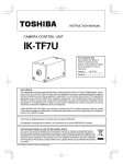
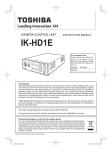
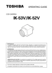
11. EXTERNAL APPEARANCE DIAGRAM
Unit : mm [inch]
26
5
2-M3 Depth 3
44
6.3
78
12
(AWB)
DISP
MENU DATA
DC IN 12V
5
56
4-M3 Depth 3
25
No.4-40UNC
26
25
26
5
10.7
22
34
44
PAGE
RGB
25
4-M2 Depth 3
12. BEFORE MAKING A SERVICE CALL
Symptom
No image
Poor color
•
•
•
•
•
•
•
•
Items to be checked
Is the power supplied correctly?
Is the lens iris adjusted correctly?
Are the cables connected correctly?
Is the shutter mode set correctly?
Is the image process equipment set correctly?
Is the monitor (TV) adjusted correctly?
Is the white balance of the camera adjusted correctly?
Is the illumination dark?
35
LIMITED WARRANTY
TOSHIBA CCD CAMERA
Promptly register your product with Toshiba on-line at www.toshiba.com/taisisd. By registering your product you will be eligible for periodic updates, announcements, and special offers. You will have access to extended
warranty options, upgrades (as applicable), useful tips, on-line troubleshooting, and the ability to schedule service
on-line if necessary. The Imaging Systems Division of Toshiba America Information Systems, Inc. ("ISD") makes
the following limited warranties. These limited warranties extend to the Original End-User ("Your[r]").
Limited One (1) Year Warranty of Labor and Parts
ISD warrants this product and parts against defects in material or workmanship for a period of one year from the
date of original retail purchase by the end-user. During this period, ISD will repair or replace a defective product or
part with a new or refurbished item. The user must deliver the entire product to an ISD authorized service center.
The user is responsible for all transportation and insurance charges for the product to the Service Center. ISD
reserves the right to substitute Factory Refurbished Parts and / or Factory Refurbished Product in place of those
in need of repair.
Step-by-step Procedures - How to Obtain Warranty Service
[1] Verify operation of the unit by checking the instruction manual
[2] If there is a defect in material or workmanship, contact an Authorized Service Provider within 30 days after the
product fails to comply with specifications.
[3] Arrange for delivery of the product to the ISD authorized service center. Products must be insured and securely
packed, preferably in the original shipping carton. A letter explaining the defect and a copy of the bill of sale or
other proof of purchase must be enclosed with a complete return street address and daytime telephone number.
Charges for transportation and insurance must be prepaid by the end-user.
Questions?
If you have any questions, please check the Toshiba Imaging Systems Division Web site as
follows:
Website:
http://www.toshiba.com/taisisd/indmed
Your Responsibility, warranties are subject to the following conditions:
[1] You must retain the bill of sale or provide other proof of purchase.
[2] You must schedule service within thirty days after you discover a defective product or part.
[3] All warranty servicing of this product must be made by a Toshiba ISD Authorized Service Provider.
[4] The warranty extends to defects in material or workmanship as limited above, and not to any products or parts
that have been lost or discarded by user. The warranty does not cover damage caused by misuse, accident,
improper installation, improper maintenance, or use in violation of instructions furnished by ISD. The warranty
does not extend to units which have been altered or modified without authorization of ISD, or to damage to products or parts thereof which have had the serial number removed, altered defaced or rendered illegible.
ALL WARRANTIES IMPLIED BY STATE LAW, INCLUDING THE IMPLIED WARRANTIES OF MERCHANTABILITY AND FITNESS FOR A PARTICULAR PURPOSE, ARE EXPRESSLY LIMITED TO THE DURATION OF
THE LIMITED WARRANTIES SET FORTH ABOVE. Some states do not allow limitations on how long an
implied warranty lasts, so the above limitation may not apply. WITH THE EXCEPTION OF ANY WARRANTIES IMPLIED BY STATE LAW AS HEREBY LIMITED, THE FOREGOING EXPRESS WARRANTY IS EXCLUSIVE AND IN LIEU OF ALL OTHER WITH RESPECT TO THE REPAIR OR REPLACEMENT OF ANY PRODUCTS OR PARTS. IN NO EVENT SHALL ISD BE LIABLE FOR CONSEQUENTIAL OR INCIDENTAL DAMAGES. Some states do not allow the exclusion or limitation of incidental or consequential damages so the
above limitation may not apply.
No person, agent, distributor, dealer, service station or company is authorized to change, modify or extend the terms of these warranties in any manner whatsoever. The time within which an action must be
commenced to enforce any obligation of ISD arising under this warranty or under any statute, or law of the
United States or any state thereof, is hereby limited to one year from the date you discover or should have
discovered, the defect. This limitation does not apply to implied warranties arising under state law. Some
states do not permit limitation of the time within which you may bring an action beyond the limits provided
by state law so the above provision may not apply to user. This warranty gives the user specific legal
rights, and user may also have other rights, which may vary from state to state.
TOSHIBA AMERICA INFORMATION SYSTEMS, INC.
Imaging Systems Division
Copyright © 2002 Toshiba America, Inc. All rights reserved.