1
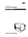
TEC Thermal Printer
B-880-QQ SERIES
Owner’s Manual
This equipment has been tested and found to comply with the limits for a Class A digital device,
pursuant to Part 15 of the FCC Rules. These limits are designed to provide reasonable protection
against harmful interference when the equipment is operated in a commercial environment. This
equipment generates, uses, and can radiate radio frequency energy and, if not installed and used in
accordance with the instruction manual, may cause harmful interference to radio communications.
Operations of this equipment in a residential area is likely to cause harmful interference in which case
the user will be required to correct the interference at his own expense.
(for USA only)
Changes or modifications not expressly approved by manufacturer for compliance could void the
user's authority to operate the equipment.
"This Class A digital apparatus meets all requirements of the Canadian Interference-Causing
Equipment Regulations."
"Cet appareil numérique de la classe A respecte toutes les exigences du Règlement sur le matériel
brouilleur de Canada."
(for CANADA only)
WARNING!
This is a Class A product. In a domestic environment this product may cause radio interference in
which case the user may be required to take adequate measures.
CAUTION:
Do not touch moving parts. To reduce the risk that fingers, jewelry, clothing, etc., be drawn into the
moving parts, push the switch in the "OFF" position to stop movement.
As an ENERGY STAR® Partner, TOSHIBA TEC has determined that
this product meets the ENERGY STAR® guidelines for energy efficiency.
-- Outline of the International ENERGY STAR® Office Equipment Program -The International ENERGY STAR® Office Equipment Program is an international program that
promotes energy saving through the penetration of energy efficient computers and other office
equipment. The program backs the development and dissemination of products with functions that
effectively reduce energy consumption. It is an open system in which business proprietors can
participate voluntarily. The targeted products are office equipment such as computers, monitors,
printers, facsimiles, copiers, scanners, and multifunction devices. Their standards and logos are
uniform among participating nations.
ENERGY STAR is a U.S. registered mark.
Copyright © 2002
by TOSHIBA TEC CORPORATION
All Rights Reserved
570 Ohito, Ohito-cho, Tagata-gun, Shizuoka-ken, JAPAN
EO1-33017
Safety Summary
Safety Summary
Personal safety in handling or maintaining the equipment is extremely important. Warnings and Cautions
necessary for safe handling are included in this manual. All warnings and cautions contained in this
manual should be read and understood before handling or maintaining the equipment.
Do not attempt to effect repairs or modifications to this equipment. If a fault occurs that cannot be rectified
using the procedures described in this manual, turn off the power, unplug the machine, then contact your
authorized TOSHIBA TEC representative for assistance.
Meanings of Each Symbol
This symbol indicates warning items (including cautions).
Specific warning contents are drawn inside the symbol.
(The symbol on the left indicates a general caution.)
This symbol indicates prohibited actions (prohibited items).
Specific prohibited contents are drawn inside or near the symbol.
(The symbol on the left indicates “no disassembling”.)
This symbol indicates actions which must be performed.
Specific instructions are drawn inside or near the symbol.
(The symbol on the left indicates “disconnect the power cord plug from the outlet”.)
WARNING
Any other than the
specified AC voltage
is prohibited.
This indicates that there is the risk of death or serious injury if the
machines are improperly handled contrary to this indication.
Do not use voltages other than the
voltage (AC) specified on the rating
plate, as this may cause fire or
electric shock.
Prohibited
Do not plug in or unplug the power
cord plug with wet hands as this may
cause electric shock.
Prohibited
If the machines share the same
outlet with any other electrical
appliances which consume large
amounts of power, the voltage will
fluctuate widely each time these
appliances operate. Be sure to
provide an exclusive outlet for the
machine as this may cause the
machines to malfunction.
Prohibited
Do not place metal objects or
water-filled containers such as flower
vases, flower pots or mugs, etc. on
top of the machines. If metal objects
or spilled liquid enter the machines,
this may cause fire or electric
shock.
Prohibited
Do not insert or drop metal,
flammable or other foreign objects into
the machines through the ventilation
slits, as this may cause fire or electric
shock.
Prohibited
Do not scratch, damage or modify
the power cords. Also, do not place
heavy objects on, pull on, or excessively bend the cords, as this may
cause fire or electrical shock.
Disconnect
the plug.
If the machines are dropped or their
cabinets damaged, first turn off the
power switches and disconnect the
power cord plugs from the outlet, and
then contact your authorized
TOSHIBA TEC representative for
assistance. Continued use of the
machine in that condition may cause
fire or electric shock.
Disconnect
the plug.
Continued use of the machines in an
abnormal condition such as when the
machines are producing smoke or
strange smells may cause fire or electric shock. In these cases, immediately turn off the power switches and
disconnect the power cord plugs from
the outlet. Then, contact your authorized TOSHIBA TEC representative for
assistance.
(i)
EO1-33017
Safety Summary
Disconnect
the plug.
Connect a
grounding
wire.
If foreign objects (metal fragments,
water, liquids) enter the machines,
first turn off the power switches and
disconnect the power cord plugs from
the outlet, and then contact your
authorized TOSHIBA TEC representative for assistance. Continued
use of the machine in that condition
may cause fire or electric shock.
Disconnect
the plug.
When unplugging the power cords,
be sure to hold and pull on the plug
portion. Pulling on the cord portion
may cut or expose the internal wires
and cause fire or electric shock.
Ensure that the equipment is
properly grounded. Extension cables
should also be grounded. Fire or
electric shock could occur on
improperly grounded equipment.
No disassembling.
Do not remove covers, repair or
modify the machine by yourself. You
may be injured by high voltage, very
hot parts or sharp edges inside the
machine.
indicates that there is the risk of personal Injury or damage to
CAUTION This
objects if the machines are improperly handled contrary to this indication.
Precautions
The following precautions will help to ensure that this machine will continue to function correctly.
• Try to avoid locations that have the following adverse conditions:
* Temperatures out of the specification
* Direct sunlight
* High humidity
* Shared power source
* Excessive vibration
* Dust/Gas
• The cover should be cleaned by wiping with a dry cloth or a cloth slightly dampened with a mild
detergent solution. NEVER USE THINNER OR ANY OTHER VOLATILE SOLVENT on the plastic
covers.
• USE ONLY TOSHIBA TEC SPECIFIED paper and ribbons.
• DO NOT STORE the paper or ribbons where they might be exposed to direct sunlight, high temperatures, high humidity, dust, or gas.
• Ensure the printer is operated on a level surface.
• Any data stored in the memory of the printer could be lost during a printer fault.
• Try to avoid using this equipment on the same power supply as high voltage equipment or equipment likely to cause mains interference.
• Unplug the machine whenever you are working inside it or cleaning it.
• Keep your work environment static free.
• Do not place heavy objects on top of the machines, as these items may become unbalanced and fall
causing injury.
• Do not block the ventilation slits of the machines, as this will cause heat to build up inside the
machines and may cause fire.
• Do not lean against the machine. It may fall on you and could cause injury.
• Care must be taken not to injure yourself with the printer paper cutter.
• Unplug the machine when it is not used for a long period of time.
Request Regarding Maintenance
•
Utilize our maintenance services.
After purchasing the machine, contact your authorized TOSHIBA TEC representative for assistance
once a year to have the inside of the machine cleaned. Otherwise, dust will build up inside the
machines and may cause a fire or a malfunction. Cleaning is particularly effective before humid
rainy seasons.
•
Our preventive maintenance service performs the periodic checks and other work required to
maintain the quality and performance of the machines, preventing accidents beforehand.
For details, please consult your authorized TOSHIBA TEC representative for assistance.
•
Using insecticides and other chemicals
Do not expose the machines to insecticides or other volatile solvents. This will cause the cabinet or
other parts to deteriorate or cause the paint to peel.
(ii)
EO1-33017
TABLE OF CONTENTS
Page
1.
INTRODUCTION ....................................................................................1- 1
1.1 APPLICABLE MODEL ...................................................................1- 1
1.2 ACCESSORIES .............................................................................1- 1
2. SPECIFICATIONS .................................................................................2- 1
2.1 PRINTER .......................................................................................2- 1
2.2 OPTION .........................................................................................2- 2
2.3 MEDIA ............................................................................................2- 3
2.4 RIBBON .........................................................................................2- 3
3. OVERVIEW ............................................................................................3- 1
3.1 FRONT/REAR VIEW......................................................................3- 1
3.2 OPERATION PANEL .....................................................................3- 1
4. PARAMETER SETTING FUNCTIONS ..................................................4- 1
5. SET UP PROCEDURE ...........................................................................5- 1
5.1 REQUIREMENTS FOR OPERATION ...........................................5- 1
5.2 SETTING UP THE PRINTER.........................................................5- 1
6. INSTALLATION PROCEDURE .............................................................6- 1
6.1 CONNECTING THE POWER CORD AND CABLES ..................... 6- 1
6.2 HOLDER STAND INSTALLATION ................................................6- 2
7. LOADING THE RIBBON ........................................................................7- 1
8. LOADING THE MEDIA ..........................................................................8- 1
9. INSERTING THE OPTIONAL PCMCIA CARD ......................................9- 1
10. CARE/HANDLING OF THE MEDIA AND RIBBON .............................10- 1
11. GENERAL MAINTENANCE ................................................................11- 1
11.1 CLEANING ...................................................................................11- 1
11.2 UNDER THE MEDIA GUIDES ..................................................... 11- 3
11.3 COVERS AND PANELS .............................................................. 11- 3
11.4 REMOVING JAMMED MEDIA ..................................................... 11- 4
11.5 THRESHOLD SETTING .............................................................. 11- 6
12. TROUBLESHOOTING .........................................................................12- 1
CAUTION:
1. This manual may not be copied in whole or in part without prior written permission of
TOSHIBA TEC.
2. The contents of this manual may be changed without notification.
3. Please refer to your local Authorized Service representative with regard to any queries
you may have in this manual.
EO1-33017
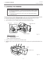
1. INTRODUCTION
1.1 APPLICABLE MODEL
1. INTRODUCTION
Thank you for choosing the TEC B-882 Series thermal/transfer printer. This new generation high
performance/quality printer is equipped with the latest hardware including the newly developed high
density (12 dot/mm, 305 dot/inch) edge print head. This will allow very clear print at a maximum speed
of 203.2 mm/sec. (8 inch/sec.). Other standard features include an automatic ribbon saver and external
media supply.
Optional features include a strip mechanism and Cutter mechanism.
This manual contains general set-up and maintenance information and should be read carefully to help
gain maximum performance and life from your printer. For most queries please refer to this manual and
keep it safe for future reference.
1.1 APPLICABLE MODEL
• B-882-TS10-QQ
• B-882-TS10-QQ-US
Model name description
B - 8 8 2 - T S 1 0 - Q Q
Destination Code
QQ-US: North America block, QQ: Except for QQ-US
Issue mode
S: Batch
Resolution
T: 12 dot/mm (305 dpi)
Thermal direct/Thermal transfer
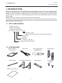
1.2 ACCESSORIES
Owner's Manual
(EO1-33017)
Power Cord
Print Head Cleaner
(24089500013)
Media Holder
Holder Shaft
Left/Right Side Holder
Holder Base
Thumbscrew
(M-4x6)
Quality control report
1-1
EO1-33017
2. SPECIFICATIONS
2.1 PRINTER
2. SPECIFICATIONS
2.1 PRINTER
Model
B-882-QQ
Item
Supply voltage
Power consumption
Operating temperature
range
Relative humidity
Print head
Printing methods
Print speeds
Maximum print width
Dispensing modes
Message display
Dimensions
Weight
Available bar-code types
Two-dimensional code
Fonts
Rotations
Standard interfaces
Optional interface
Universal (automatic switching)
85-138 V, 50/60 Hz
187-276 V, 50/60 Hz
Be sure to use a power cord which meets the standard.
3.5 A, 260 W maximum (standby: 360 mA, 20 W maximum)
5˚C ~ 40˚C
25% ~ 85%RH (no condensation)
Thermal print head 12 dots per mm (305 dots per inch)
Thermal direct or Thermal transfer
76.2 mm/sec. (3 inch/sec.), 101.6 mm/sec. (4 inch/sec.),
203.2 mm/sec. (8 inch/sec.) When the media width is 160 mm or less.
213.3 mm (8.40 inches)
Batch (Continuous), Strip (On-demand) and Cut modes
(Both cut and strip modes are available only when their respective modules
are fitted.)
20 characters x 1 line
437 mm (width) x 282 mm (depth) x 395 mm (height)
26 kg (without media and ribbon)
JAN8, JAN13, EAN8, EAN8 + 2 digits, EAN8 + 5 digits
EAN13, EAN13 + 2digits, EAN13 + 5 digits
UPC-E, UPC-E + 2 digits, UPC-E + 5 digits
UPC-A, UPC-A + 2 digits, UPC-A + 5 digits
MSI, ITF, NW-7, CODE39, CODE93, CODE128
EAN128, Industrial 2 to 5, Customer Bar Code, POSTNET, KIX CODE,
RM4SCC (ROYAL MAIL 4STATE CUSTOMER CODE),
Data Matrix, PDF417, QR Code, Maxi Code, Micro PDF417
Times Roman (6 sizes), Helvetica (6 sizes), Presentation (1 size),
Letter Gothic (1 size), Prestige Elite (2 sizes), Courier (2 sizes),
OCR (2 types), Writable characters (40 types, 2-byte character available),
Outline font (4 types), Price font (3 types)
0˚, 90˚, 180˚, 270˚
Serial interface (RS-232C)
Parallel interface (Centronics)
Expansion I/O interface
PCMCIA interface
∗ Data MatrixTM is a trademark of International Data Matrix, Inc.
PDF417 is a trademark of Symbol Technologies, Inc.
2-1
EO1-33017
2. SPECIFICATIONS
2.2 OPTION
■ Auto Ribbon Saving Mode
Auto ribbon saving function is activated by Parameter Settings (Refer to your authorized
TOSHIBA TEC representative) and none print area extends for more than 20 mm.
NOTES: 1. To activate ribbon saving function at a speed of 8"/sec., the no print area should extend
more than 25 mm.
2. Depending on the relationship between the outer diameter of rewound ribbon and print
speed, ribbon usage may vary as follows:
Print speed
3"/sec
Ribbon loss
Approx. 5 mm
4"/sec
8"/sec
Approx. 10 mm
Approx. 23 mm
3. Please contact your authorised TOSHIBA TEC representative to change the
Operation Panel setting.
2.2 OPTION
Option Name
Type
Description
Source
Cutter module
B-4208-QM
A stop and cut swing cutter
Strip module
B-4908-H-QM
This module strips the label from the back- See NOTE 1.
ing paper with the take-up block and strip
block.
PCMCIA interface
board
B-8700-PC-QM
This board enables the following PCMCIA See NOTE 1.
cards to be used.
* LAN card: 3 COM EtherLink®III (recommended)
* ATA card: Conforming to PC card ATA
standard
* Flash memory card: 4MB card (See Page
See NOTE 1.
10-1.)
NOTES:1. Available from your nearest TOSHIBA TEC representative or TOSHIBA TEC Head
Quarters.
2-2
EO1-33017
2. SPECIFICATIONS
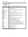
2.3 MEDIA
2.3 MEDIA
Label
Stop
position
I
Refer to the following
NOTE 2.
Black Mark
(on reverse side)
Stop
position
Tag paper
Black Mark
(on reverse side)
I
Tag paper
E
F
Cut
position
Cut
position
J
H
Reference
coordinate 1
Reference
coordinate 1
A
Reference
coordinate 2
G
D
C
Label dispensing mode
Item
A : Span of one label/tag
B:
C:
D:
E:
F:
G:
H:
Label length
Width including backing paper
Label width
Gap length
Black mark length (Tag paper)
Effective print width
Standard
Label
Effective
print length
Standard
Tag
A
H
B
Reference
coordinate 2
Feed direction
G
C
Fig. 2-1
[Unit: mm]
Batch mode
Strip mode
10.00 ~ 1368.0
25.4 ~ 1368.0
7.5 ~ 1366.0
5.5 ~ 1364.0
22.9 ~ 1366.0
101.6 ~ 225.0
98.6 ~ 222.0
2.5 ~ 20.0
2.5 ~ 10.0
10.0 ~ 213.3
20.9 ~ 1364.0
8.0 ~ 1364.0
---
2.5 ~ 20.0
I : Print speed up/slow down area
J : Black mark length (Label)
Cut mode
Label: 38 ~ 1368.0
Tag: 25.4 ~ 1368.0
25.0 ~ 1362.0
6.0 ~ 20.0
23.0 ~ 1364.0
23.4 ~ 1364.0
1.0
Refer to the following NOTE 2.
682.0
Standard
Maximum effective
length for on the fly issue
Outer roll diameter
Label
Thickness
Tag
Ø200 Max.
0.13 ~ 0.17
0.10 ~ 0.17
NOTES: 1. The media specification other than above are unchanged.
2. When marking black marks on label rolls, the following requirements must be satisfied.
When the gap length is less than 4 mm:
The black mark length should be longer than the gap length.
When the gap length is 4 mm or more:
The black mark should not overlap the gap for more than 4 mm and the following label.
3. When issuing thermal labels at 8"/sec., the print stop position should be set to a minimum of 1 mm inside
the label.
2.4 RIBBON
Type
Width
Length
Outer diameter
NOTES: 1. “On the fly issue” means that the printer can draw and print without stopping
between labels.
Spool type
2. To ensure print quality and print head life use only TOSHIBA TEC specified
media and ribbons.
115 mm ~ 224 mm
3. When using the cutter ensure that label length B plus inter label gap length
E exceeds 35 mm. (i.e. label pitch should be greater than 35 mm.)
300 m
4. Use of rough media for the ribbon saving issue may cause ribbon smudges.
Ø72 mm (max.)
5. To avoid ribbon wrinkles use the ribbon which is wider than media by 5mm
or more. However, too much difference in width between the two may
cause wrinkles.
2-3
EO1-33017
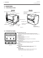
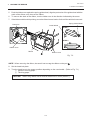
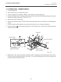
3. OVERVIEW
3.1 FRONT/REAR VIEW
3. OVERVIEW
3.1 FRONT/REAR VIEW
Front View
Rear View
Message Display (LCD)
Serial Interface
Connector
(RS-232C)
Top Cover
Head Lever
PCMCIA Card Slot
(2 slots)
Right Side Cover
AC Power Inlet
Operation Panel
Media Outlet
Power Switch
0: OFF
1: ON
Parallel I/F Connector
(Centronics)
Fig. 3-1
Expansion I/O
Interface Connector
3.2 OPERATION PANEL
MESSAGE DISPLAY (LCD)
Displays messages in the language selected by DIP switch.
When power is turned on and it is ready to print, “ON LINE” is
displayed.
POWER
ON LINE
ERROR
POWER LED (Green)
Lights when the power is turned on.
ON-LINE LED (Green)
1) Flashes when communicating with a host computer.
2) On while printing.
FEED
RESTART
PAUSE
ERROR LED (Red)
Lights when a communication error occurs, when the media/ribbon
ends or the printer does not operate correctly.
FEED Key
Feeds paper.
Fig. 3-2
RESTART Key
Resets the printer when paused or when an error occurs.
Used to set the threshold. (Refer to page 11-6)
PAUSE Key
Pauses printing.
Message display shows “PAUSE” and an unprinted count.
Used to set the threshold. (Refer to page 11-6)
3-1
EO1-33017
4. PARAMETER SETTING FUNCTIONS
4. DIP SWITCH FUNCTIONS
4. PARAMETER SETTING FUNCTIONS
The Following table illustrates settings that are selected only by changing the Printer's PARAMETER
settings. This procedure can be found in the Maintenance Manual section of the B-880 Series SERVICE
MANUAL under section 6.3. Please Contact your authorized TOSHIBA TEC representative to change the
operation panel settings.
■ Parameter Setting Mode Table
Mode Name
SPEED
DATA LENG.
STOP BIT
PARITY
XON+READY
LCD
FORWARD WAIT
HEAD UP CUT
RIBBON SAVE
CODE
RIBBON
SENS POSI
Function
Baud rate of the serial interface is selected.
Data length of the serial interface is selected.
Stop bit of the serial interface is selected.
Parity of the serial interface is selected.
Transmission control mode of the serial interface is selected.
Language which displays LCD message is selected.
Auto forward wait in cut mode is selected. When idle for 3 seconds or
more after cutting, the printer automatically feeds the paper 10mm
forward.
Print head up in cut mode is selected. If a back feed is performed when
this parameter is ON, it is done while the print head is up. (Available
only when the ribbon saving module is installed and the ribbon save
mode is ON.)
The ribbon saving module is selected. Be sure to set this parameter to
ON when using the ribbon saving module.
The command code out of AUTO, ESC/LF/NUL, or { I } is selected.
Ribbon type either transmissive or non-transmissive is selected.
The media sensor position is selected.
CENTER: Fixed
EDGE:
Movable
4-1
EO1-33017
5. SET UP PROCEDURE
5.1 REQUIREMENTS FOR OPERATION
5. SET UP PROCEDURE
5.1 REQUIREMENTS FOR OPERATION
The B-882 has the following requirements:
• The host computer must have a serial port or centronics parallel port.
• To communicate with host, either an RS-232C cable or Centronics cable is required.
(1) RS-232C cable .......... 25 pins
(2) Centronics cable ....... 36 pins
• To print the format, create the complete program using the interface/communication manual.
■ Interface Cables
To prevent radiation and reception of electrical noise, the interface cables must meet the following
requirements:
• Fully shielded and fitted with metal or metalised connector housings.
• Kept as short as possible.
• Should not be bundled tightly with power cords.
• Should not be tied to power line conduits.
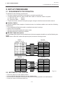
■ RS-232C Cable description
The serial data cable used to connect the printer to the host computer should be one of the following two
types:
NOTE: Use an RS-232C cable with imperial (inch) connector securing screws.
DB-25P
Connector to Printer
DB-9S
Connector to PC
PIN No.
1
2
3
4
5
6
7
8
9
Housing
Signal
N.C.
RXD
TXD
DTR
GND
DSR
RTS
CTS
N.C.
Shield
Signal
Shield
TXD
RXD
RTS
CTS
DSR
GND
DTR
3
2
20
7
6
4
5
TXD
RXD
DSR
GND
DTR
CTS
RTS
Housing
Shield
PIN No.
Signal
3
2
20
7
6
4
5
TXD
RXD
DSR
GND
DTR
CTS
RTS
Fig. 5-1
5.2 SETTING UP THE PRINTER
•
•
•
•
Signal
DB-25P
Connector to Printer
DB-25S
Connector to PC
PIN No.
1
2
3
4
5
6
7
20
PIN No.
Place the printer on a flat, stable surface.
Use a grounded electrical outlet do not use adapter plug.
Be sure there is adequate room around the printer for easy operation and maintenance.
Keep your work environment static free.
5-1
EO1-33017
6. INSTALLATION PROCEDURE
6.1 CONNECTING THE POWER CORD AND CABLES
6. INSTALLATION PROCEDURE
6.1 CONNECTING THE POWER CORD AND CABLES
WARNING!
Turn the POWER SWITCH to OFF before connecting the power cord or cables.
Power Cord
Fig. 6-1
Serial I/F Cable (RS-232C)
Parallel I/F Cable
(Centronics)
NOTE:
Expansion I/O Cable
Different cables cannot be used at the same time.
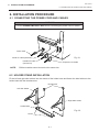
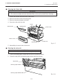
6.2 HOLDER STAND INSTALLATION
Fit the left and right side holders into the dowels of the holder base and fasten the side holders to the
holder base with the thumbscrews.
Thumbscrew
Left Side Holder
Right Side Holder
Holder Base
Fig. 6-2
Dowel
6-1
EO1-33017
7. LOADING THE RIBBON
7. LOADING THE RIBBON
7. LOADING THE RIBBON
WARNING!
1. Do not touch moving parts. To reduce the risk that fingers, jewelry, clothing,
etc., be drawn into the moving parts, push the switch in the “OFF” position to
stop movement.
2. To avoid injury, be careful not to catch or jam your fingers while opening
or closing the cover.
There are two types of media available for printing on, these are standard media and direct thermal media
(a chemically treated surface). DO NOT LOAD a ribbon when using a direct thermal media.
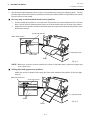
1. Turn the power off and open both the top cover and the right side cover.
2. Set the head lever to the “OPEN” position and release the head lock plate.
Head Lever
Top Cover
Right Side Cover
OPEN
1
2
Head Lock Plate
Fig. 7-1
Head Lever Position
1:
Labels or thin tag paper
2:
Thick tag paper
OPEN: Ribbon/media replacement
3. As Fig. 7-2 shows, unroll and loosen the ribbon a little.
4. Insert the ribbon under the print block so that the ribbon supply end is positioned backside of the
printer.
Ribbon
Ribbon Core
Fig. 7-2
7-1
EO1-33017
7. LOADING THE RIBBON
7. LOADING THE RIBBON
5. Push the ribbon core against the spring guide wheel, align the protrusion of the guide wheel with the
notch of the ribbon core, then set the ribbon.
6. To remove the slack of the ribbon, turn the ribbon core in the direction indicated by the arrow.
7. If the ribbon wrinkles while printing, move the ribbon levers back or forth until the wrinkle is removed.
Spring Guide Wheel
Protrusion
Guide Wheel
STEP 1
STEP 2
Notch
Ribbon Core
Ribbon
Ribbon Lever
Fig. 7-3
NOTE: When removing the ribbon, be careful not to snag the ribbon on the part
.
8. Set the head lock plate.
9. Turn the head lever to the proper position depending on the used media. (Refer to Fig. 7-1)
1: Labels or thin tag paper
2: Thick tag paper
CAUTION:
When using labels ensure that the head lever is set to position 1.
7-2
EO1-33017
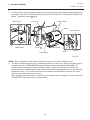
8. LOADING THE MEDIA
8. LOADING THE MEDIA
8. LOADING THE MEDIA
WARNING!
1. Do not touch moving parts. To reduce the risk that fingers, jewelry, clothing,
etc., be drawn into the moving parts, push the switch in the “OFF” position to
stop movement.
2. To avoid injury, be careful not to catch or jam your fingers while opening
or closing the cover.
1. Install the holder stand on the rear of the printer.
2. Loosen the screw A and slide the media guides outside.
Media Guides
Holder Stand
Release Lock
Screw A
Fig. 8-1
CAUTION:
DO NOT MOVE the Media Guides using the screw A .
3. Lock the Media Holder securely with the Lock Lever.
4. Pass the Holder Shaft through the Media, then set one of the Media Holders and lock it securely with
the Lock Lever.
Media Holder
Media Holder
Holder Shaft
Holder Shaft
Lock Lever
Media
Lock Lever
8-1
Fig. 8-2
EO1-33017
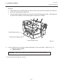
8. LOADING THE MEDIA
8. LOADING THE MEDIA
5. Turn the Lock Levers of the Media Holders to the unlock position and readjust the Media position to
the center. Then lock the Media Holders securely with the Lock Levers. Fit the Media Guides to the
Media. Tighten the screw A firmly.
Media Guide
Lock Lever
Media Holder
Media
Media Holder
Media Guide
Screw A
Holder Stand
Notch
Holder Shaft
Bush
Fig. 8-3
NOTE: Set in the bushes of the Holder Shaft into notches of the Holder Stand securely.
6. The black mark/feed gap sensor is selectable between the fixed type and the movable type by
changing the printer's PARAMETER settings. Please contact your authorized TOSHIBA TEC
representative to change the Operation Panel setting. When the fixed type is selected, the
blackmark sensor is located at the center of the media and the feed gap sensor is at 10 mm left to the
blackmark sensor. The movable sensor can be located anywhere between the left end of the
effective print width and the fixed sensor.
After changing the sensor type, the sensitivity of the sensor must be adjusted. In this case call a
TOSHIBA TEC authorized service representative.
8-2
EO1-33017
8. LOADING THE MEDIA
8. LOADING THE MEDIA
7. Set the black mark/feed gap sensor to the correct position by turning the adjusting knob. Turning
the knob right will move the sensor towards the center of the media while turning left will move it away
from the center of the media.
■ An easy way to set the black mark sensor position
1
2
Pull the media about 500 mm out of the front of the printer, turn the media back on it’s self and
feed it under the print head past the sensor so that the black mark can be seen from above.
Adjust the sensor position to that of the black mark (the upper hole indicates the position of the
black mark sensor).
(Feed Gap Sensor)
Black Mark Sensor
Adjusting Knob
Black Mark
Media
Fig. 8-4
NOTE: Make sure to set the sensor to detect the center of the black mark, otherwise a paper jam
error could occur.
■ Setting the feed gap sensor position
Adjust the sensor to detect on the gap (the lower hole indicates the position of the feed gap
sensor).
(Black Mark Sensor)
Feed Gap Sensor
Adjusting Knob
Media
Fig. 8-5
Media
8-3
EO1-33017
8. LOADING THE MEDIA
8. LOADING THE MEDIA
8. The media is now loaded and the sensor position is set.
Batch type:
Media
Fig. 8-6
Cutter type: Where a cutter is fitted load the media as standard and feed it through the cutter
module.
NOTES: 1. Be sure to cut the backing paper of label. Cutting label will cause the glue to stick to the
cutter, which may affect the cutter quality and shorten the cutter life.
2. If the top edge of label winds onto the platen in cut issue, have the printer's PARAMETER
setting adjusted for auto feed after cut. Please contact your authorized TOSHIBA TEC
representative to change the Operation Panel setting.
3. Use of tag paper with the thickness exceeding the specified valve may affect the cutter life.
Cutter Module
Media Outlet
Media
Fig. 8-7
8-4
EO1-33017
8. LOADING THE MEDIA
8. LOADING THE MEDIA
Strip type:
1
2
3
Strip labels from the backing paper for about 200-mm long from the top edge of the label roll.
Lower the backing paper release bar.
Pass the backing paper between the strip roller and the backing paper holder. After taking up
any slack of the media, set the backing paper release bar in position.
Media (Backing Paper)
Backing Paper Release Bar
Backing Paper Holder
Fig. 8-8
9. Turn the head lever to the proper position depending on the used media. (Refer to Fig. 7-1)
1: Labels or thin tag paper
2: Thick tag paper
CAUTION:
When using labels ensure that the head lever is set to position 1.
10. Close the top and right side covers.
8-5
EO1-33017
9. INSERTING THE OPTIONAL PCMCIA CARD
9. INSERTING THE OPTIONAL PCMCIA CARD
9. INSERTING THE OPTIONAL PCMCIA CARD
WARNING:
Turn the power OFF when inserting or removing the PCMCIA card.
CAUTION:
To protect PCMCIA cards, discharge static electricity from your body by touching the printer rear
cover prior touching the PCMCIA cards.
1. Turn the power off.
2. Insert the PCMCIA card into the card slot at the rear of the printer.
3. Turn the power on.
2
1
PCMCIA Card
Fig. 9-1
NOTES: 1. Be sure to protect a PCMCIA card when not in use in the printer by putting it in its protective
cover.
2. Do not subject the card to any shocks or excessive forces.
3. Do not expose the card to extremes of heat by either storing in direct sunlight or close to a
heater.
4. Do not expose the card to excessive humidity by wiping it with a wet cloth or storing it in a
damp place.
5. Before inserting or removing the card, make sure that the power switch is turned off.
6. The following PCMCIA cards can be used.
Type
Maker
Description
ATA Card
A card conforming to the PC card ATA standard
LAN Card
3 COM
Remarks
Ether Link III 3C589D PC Install into the slot (2) only.
card
(This card installed into the
slot (1) will not work.)
Flash Memory
Card (4 MB)
EF-4M-TB CC
Maxell
EF-4M-TB DC
7. Install the LAN card into the slot (2).
9-1
EO1-33017
10. CARE/HANDLING OF THE MEDIA AND RIBBON
10. CARE/HANDLING OF THE MEDIA AND RIBBON
10. CARE/HANDLING OF THE MEDIA AND RIBBON
CAUTION:
Be sure to read carefully and understand the Supply Manual. Use only media and ribbon
which meet specified requirements. Use of non-specified media and ribbon may shorten the
head life and result in problems with bar code readability or print quality. All media and ribbon
should be handled with care to avoid any damage to the media, ribbon or printer. Read the
following guideline carefully.
•
Do not store the media and ribbon for longer than the manufactures recommended shelf life.
•
Store media rolls on the flat end, do not store them on the curved sides as this might flatten that side
causing erratic media advance and poor print quality.
•
Store the media in plastic bags and always reseal after opening. Unprotected media can get dirty
and the extra abrasion from the dust and dirt particles will shorten the print head life.
•
Store the media and ribbon in a cool, dry place. Avoid areas where they would be exposed to direct
sunlight, high temperature, high humidity, dust or gas.
•
The thermal paper used for direct thermal printing must not have the specifications which exceed
Na+ 800 ppm, K+ 250 ppm and CL- 500 ppm.
•
Some ink used on pre-printed labels may contain ingredients which shorten the print head’s product
life. Do not use labels pre-printed with ink which contain hard substances such as carbonic calcium
(CaCO3) and kaolin (Al2O3, 2SiO2, 2H2O).
For further information please contact your local distributor or your media and ribbon manufacturer.
10-1
EO1-33017
11. GENERAL MAINTENANCE
11.1 CLEANING
11. GENERAL MAINTENANCE
1.
2.
3.
4.
WARNING!
Be cafeful when handling the print head as it becomes very hot.
Care must be taken not to injure yourself with the printer paper cutter.
Do not touch moving parts. To reduce the risk that fingers, jewelry, clothing,
etc., be drawn into the moving parts, push the switch in the “OFF” position to
stop movement.
To avoid injury, be careful not to catch or jam your fingers while opening
or closing the cover.
11.1 CLEANING
WARNING!
1. Be sure to disconnect the power cord prior to performing any maintenance.
2. Do not use any tool that may damage the print head.
3. DO NOT POUR WATER directly onto the printer.
To help retain the high quality and performance of your printer it should be regularly cleaned. The greater
the usage of the printer, the more frequent the cleaning. (i.e. low usage=weekly : high usage=daily).
1. Turn the power off.
2. Open the top cover and right side cover.
3. Turn the head lever to raise the print head.
4. Remove the ribbon and media.
5. Clean the element of print head with print head cleaner.
6. Clean the platen with an alcohol moistened cloth.
Print Head
Element
Print Head
Platen
Print Head Cleaner
(24089500013)
Element
Fig. 11-1
11-1
EO1-33017
11. GENERAL MAINTENANCE
11.1 CLEANING
7. Turn the pinch roller lever to the right.
8. Remove the white screw and detach the ribbon end sensor plate.
White Screw
Stud
Stud
Ribbon End Sensor Plate
Pinch Roller Lever
Fig. 11-2
NOTE:
When installing the ribbon end sensor plate, be sure to fit both studs in the notches of the ribbon
end sensor plate.
9. Remove the pinch roller block, then clean the roller belt and feed roller with cloth moistened by
alcohol.
Roller Belt
Pinch Roller Block
Feed Roller
Fig. 11-3
10. Reassemble the pinch roller block in the reverse order of removal.
11-2
EO1-33017
11. GENERAL MAINTENANCE
11.2 UNDER THE MEDIA GUIDES
11.2 UNDER THE MEDIA GUIDES
1. Remove the Media Guides.
Screw
Media Guide
Screw
Media Guide
Fig. 11-4
2. Remove the jammed Media.
3. Clean “dust and glue” on the Media Guides with a soft cloth moistened with alcohol.
4. Remount the Media guides using the screws.
NOTE: Be careful NOT TO LOSE the screw.
11.3 COVERS AND PANELS
The covers should be cleaned by wiping with a dry cloth or a cloth slightly dampened with a mild detergent
solution.
NOTE:
Clean printer cover with an electrostatic free cleaner for automated office equipment.
WARNING!
1.
2.
3.
4.
DO NOT POUR WATER directly onto the printer.
DO NOT APPLY cleaner or detergent directly onto any cover or panel.
NEVER USE THINNER OR OTHER VOLATILE SOLVENT on the plastic covers.
DO NOT clean the panel covers or the supply window with alcohol as it may cause them to
discolor, loose their shape or develop structural weakness.
11-3
EO1-33017
11. GENERAL MAINTENANCE
11.4 REMOVING JAMMED MEDIA
11.4 REMOVING JAMMED MEDIA
1. Turn the power off.
2. Open the top cover, and right side cover.
3. Turn the head lever to position “OPEN, “ then release the head lock plate.
4. Remove the white screw, unclamp and disconnect the connector of the media guide plate, and then
detach the media guide plate. (See Fig. 11-5.)
5. Remove the ribbon and media.
6. Remove the jammed media. DO NOT USE any sharp implement or tool as these could damage the
printer.
7. Clean the print head and platen, then remove any further dust or foreign substances.
8. Place the portion
of the media guide plate on the media sensor. Secure the media guide plate
with the white screw.
Connector
Media Sensor
Media Guide Plate
Clamp
Media Guide Plate
White Screw
(24741710304)
Fig. 11-5
9. Media jams in the cutter unit can be caused by wear or residual glue from label stock on the cutter.
Do not use none specified media in the cutter. If you get frequent jams in the cutter contact your
Authorized Service representative.
11-4
EO1-33017
11. GENERAL MAINTENANCE
11.4 REMOVING JAMMED MEDIA
■ Cleaning the Cutter Unit
WARNING!
1. Be sure to turn the power off before cleaning the cutter unit.
2. The cutters are sharp and care should be taken not to injure yourself when cleaning.
1. Loosen two screws and remove the cutter cover.
2. Remove the white screw and media guide.
3. Remove the jammed paper and trash.
4. Clean the cutter with dry cloth.
Screw
White Screw
Media Guide
Fixed Cutter
Cutter Cover
Swing Cutter
Cutter Unit
Fig. 11-7
5. Assembling is reverse order of removal.
■ Cleaning the strip unit
WARNING!
Be sure to turn the power off before cleaning the strip unit.
1. Lower the backing paper release bar to remove the jammed media.
2. Clean the strip roller and backing paper holder with ethyl alcohol.
Strip Roller
Backing Paper Holder
Backing Paper Release Bar
Fig. 11-8
11-5
EO1-33017
11. GENERAL MAINTENANCE
11.5 THRESHOLD SETTING
11.5 THRESHOLD SETTING
For the printer to maintain a constant print position it uses the transmissive sensor to detect the gap
between labels by measuring the amount of light passing through the media. When the media is preprinted, the darker (or more dense) inks can interfere with this process causing paper jam errors. To get
around this problem a minimum threshold can be set for the sensor in the following way.
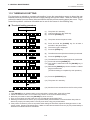
■ Threshold setting procedure
Turn the power ON.
O N
LI NE
(1)
(2)
(3)
The printer is in stand-by.
Load a media roll in the usual way.
Press the [PAUSE] key.
(4)
The printer enters the pause mode.
(5)
(6)
Press and hold the [PAUSE] key for at least 3
seconds in the pause state.
The sensor type is displayed.
(7)
Press the [FEED] key.
(8)
The reflective sensor (black mark sensor) is selected.
(9)
Press the [FEED] key again.
PAUSE
P A US E
PAUSE
T RA NS MIS S IVE
FEED
R EF LE CTI V E
FEED
T RA NS MIS S IVE
PAUSE
T RA NS MIS S IVE
(10) The transmissive sensor (feed gap sensor) is selected.
(11) Press and hold the [PAUSE] key.
(12) The media is advanced until the [PAUSE] key is
released.
(13) Release the [PAUSE] key when more than 1.5 labels
(tags) are advanced.
(Threshold setting is completed by this operation.)
P A US E
RESTART
O N
(14) Press the [RESTART] key.
(15) The printer is in stand-by.
L I NE
Command
O N
LI NE
(16) Send an issue command from the PC to the printer.
NOTES:
1. If the [PAUSE] key is released within 3 seconds whilst in pause state, paper will not feed.
2. Failure to feed more than 1.5 to 2 labels may result in an incorrect threshold setting.
3. While the print head is raised, the [PAUSE] key does not work.
4. Error such as paper end and cutter error are not detected during paper feed.
5. Selecting the transmissive sensor (for pre-printed labels) within software commands allows the printer to
detect the proper print start position correctly even when using pre-printed labels.
6. If the printer continues to print out of position after setting the threshold, adjust the feed gap sensor in the
system mode. Reset the threshold again. Make sure that the transmissive sensor (for pre-printed labels) is
selected in the feed and issue commands.
11-6
EO1-33017
12. TROUBLESHOOTING
12. TROUBLESHOOTING
12. TROUBLESHOOTING
WARNING!
If you cannot solve a problem with the following solutions, do not attempt to repair it yourself. Turn
the power off, unplug the printer, then contact your TOSHIBA TEC representative for assistance.
Error Message
PAPER JAM
Solution
Problem
1. The media is not fitted correctly.
∗∗∗∗
1. Re-fit the media correctly.
→ Press the RESTART key.
2. The media path is jammed and does not 2. Remove the cause of the jam and
replace the media correctly.
feed smoothly.
→ Press the RESTART key.
3. The installed media type does not match 3. Turn the power off then on again.
Select the correct sensor.
the selected sensor.
→ Feed the media.
4. The black mark position on the media 4. Adjust the sensor position.
→ Press the RESTART key.
does not match the sensor position.
5. The installed media size is different from 5. Turn the power off then on again.
Set the correct media size.
the programmed size.
→ Feed the media.
6. The feed gap sensor cannot see the 6. Set the threshold (see page 12-6).
Else
difference between the print area and
Turn the power off and call your
the gap.
Authorized Service representative.
HEAD OPEN
Feed or printing has been attempted while Lower the print head or raise the pinch
∗∗∗∗ the print head is raised or the pinch roller roller lever.
→ Press the RESTART key.
lever is depressed.
NO PAPER
The media has run out.
Load new media.
→ Press the RESTART key.
The ribbon has run out.
Load a new ribbon.
→ Press the RESTART key.
∗∗∗∗
NO RIBBON
∗∗∗∗
12-1
EO1-33017
12. TROUBLESHOOTING
12. TROUBLESHOOTING
Error Message
Problem
Solution
EXCESS HEAD The print head is too hot.
TEMP.
HEAD ERROR
Turn the power off and decrease the
print head temperature.
This message is displayed when sending 1. Restart the printing by pressing
the head broken check command ([ESC]
the RESTART key.
HD001 [LF] [NUL]) and the print head has a 2. Replace the print head.
broken element.
RIBBON ERROR There is a fault with the ribbon sensor.
∗∗∗∗
Turn the power off. Contact your
Authorized Service representative.
CUTTER ERROR Media is jammed in the cutter.
∗∗∗∗
Remove the jammed media and
feed the undamaged media through
the cutter.
→ Press the RESTART key.
Else
Turn the power off and contact your
Authorized Service representative.
FLASH WRITE
ERROR
An error has occurred when loading data
onto a flash memory card or ATA card.
1. Turn the power off, re-seat the flash
memory card or ATA card and try
again.
2. Replace the flash memory card
or ATA card and retry.
3. Turn the power off and contact
your Authorized Service
representative.
FORMAT
ERROR
An error has occurred while formatting a
flash memory card or ATA card.
1. Turn the power off, re-seat the flash
memory card or ATA card and try
again.
2. Replace the flash memory card
or ATA card and retry.
3. Turn the power off and contact
your Authorized Service
representative.
FLASH
MEMORY FULL
No more data can be saved in the flash
memory card or ATA card.
Replace the card with a new one
and re-send data.
(In case of flash memory card, only
4MB cards can be used.)
COMMUNICATION A communication error has occurred with Turn the power off then on again or
press the RESTART key.
ERROR
the host.
Check the program data.
→ Call your Authorized Service
representative if necessary.
12-2
EO1-33017
12. TROUBLESHOOTING
12. TROUBLESHOOTING
Error Message
example)
PC001;0A00,
Command error
Solution
Problem
When an error is detected in a command 20 Correct the command and re-send it
again.
bytes of the command are displayed.
(ESC, LF, NUL are not displayed.)
0300, 2, 2
Other Error
Message
NOTE:
Hardware or software trouble.
Turn the power off then on again. If
the problem still exists turn the power
off and contact your Authorized Service representative.
If an error is not cleared by pressing the RESTART key, the power must be switched off
then on again.
After the power has been switched off and on, all print data in the printer is cleared.
**** denotes a remaining count of unprinted labels.
Problem
Solution
No print.
1. Check that the media and the ribbon is loaded correctly.
2. Check whether the print head is set correctly or not.
3. Check the cabling between the printer and the host.
Dots missing in the
print.
Dirty print head. → Clean the print head.
Call your Authorized Service representative if necessary.
Unclear (or blurred)
printing.
1. Dirty print head. → Clean the print head.
2. Bad or faulty ribbon. → Replace ribbon.
3. Poor media quality. → Change media type.
Power does not come
on.
1. Plug power cord into an AC socket.
2. Check the circuit breakers or fuses.
3. Plug another appliance into the AC socket to check if there is power
supplied.
Call your Authorized Service representative if necessary.
Printer does not cut.
Check for a paper jam in the cutter.
Call your Authorized Service representative if necessary.
You see a raised nap
where the media has
been cut.
1. Clean the cutter blades.
2. The blades are worn.
→ Call your Authorized Service representative.
12-3
PRINTED IN JAPAN
EO1-33017