1
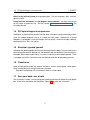
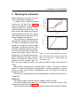
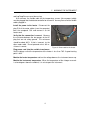
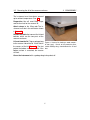
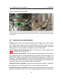
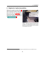
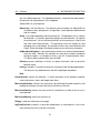
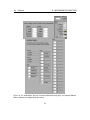
Assembly Manual
Spartan IR Camera for the SOAR Telescope
Edwin D. Loh
Department of Physics & Astronomy
Michigan State University, East Lansing, MI 48824
[email protected]
517 884-5612
09 October 2007
13 June 2008
16 May 2009
Modify procedure for assembling vacuum jacket
Add drawing of motor board
Abstract
This manual describes disassembly and assembly of the Spartan Infrared Camera.
1
1.1
Safety of the instrument and personnel
Instrument as a bomb—keep the poppet free
When the instrument warms, the cryogenic charcoal getter may release a large quantity
of gas, which vents through a poppet valve (Figure 12) if the internal pressure becomes
high. Without the poppet, the instrument may become a bomb.
1.2
Don’t open the instrument when cold
When venting the instrument to air, the instrument must be at ambient temperature. Venting when the temperature of the instrument is below the dew point will cause condensation and damage the rotation stages.
1.3
Recovery from lost vacuum
If vacuum is lost when the instrument is cold, the following procedure will prevent damage
to the rotation stages. You must pump so that ice sublimates and does not liquefy. Liquid
water will damage the lubricant on the rotation stages.
Close the leak. You have time: If the instrument is at 77 K, it will take days to warm up.
1.4
Fill liquid nitrogen in an open area
1
SAFETY
Attach a dry (oil-free) pump to the pumping port. Turn on the pump. After a minute,
open the valve.
Pump until the instrument is a few degrees above ambient. You may want to turn
on the heater to speed this up. See the section, “Warming up the instrument” in the
Assembly Manual.
1.4
Fill liquid nitrogen in an open area
Cooling the instrument from ambient must be done in an open area to avoid asphyxiation,
since the nitrogen displaces the air in a large (8m×8m) room. Operating in a closed
laboratory is acceptable, since the nitrogen in the cryostat, if it were to escape suddenly,
would merely fill a (3m×1m) closet.
1.5
Electrical—ground yourself
A detector can be damaged with electrical discharge from the body. The parts that have a
direct connection with the detector are the detector card, the controller card, and the flexible cable. When working with these, use a wrist strap that is connected to ground. There
is a copper wire on the instrument near the detector controller for grounding yourself.
1.6
Cleanliness
Keep oil from getting inside the vacuum enclosure. Use an oil-free pump. Wear gloves
when handing the parts that go inside the instrument.
Keep dust from getting in the instrument. Work in a clean room.
1.7
Save your back—use a hoist
The instrument is heavy. Use the lifting jig or rotating jig to move or rotate the cryo-optical
box. Use a hoist attached to the lifting bars (Figure 12) to move the instrument.
2
2
2
WARMING THE INSTRUMENT
Warming the instrument
Pmtorr
TK,Pmtorr
Before opening the instrument, you must
350
300
Theater
warm it up to ambient temperature.
Tdet
250
A record of the instrument warming
200
up after Run 2 of Cold Test 3 (Figure 1)
P
150
shows the temperature and pressure ris100
ing over the course of a few days. The in50
strument had been cold for 49 days. (The
0
point at which time appeared to jump for0 0.5 1 1.5 2 2.5 3
tda
ward and backward an hour later is due to
1000
some software error having to do with the
change to daylight savings time.)
100
For the first day, the temperature rose
10
slowly, because radiation transferred heat.
1
At 1.2 da, the temperature became high
0.1
enough for the getter to release nitrogen
and oxygen, and the pressure rose. Then
0.01
0 0.5 1 1.5 2 2.5 3
molecular conduction became the domitda
nant source of heat transfer, and the temperature rose rapidly. Around 1.6 da, the
Figure 1: Pressure and temperature of the detemperature rise slowed because the temtector and heater as the instrument warmed up
perature difference decreased. After the after run 3 of cold test 3. Liquid nitrogen was
heater was turned on at 2.0 da, the tem- exhausted at t=0.
perature rose with a steeper slope. Initially, the heater voltage was 80V. It was reduced to 50V at 2.3 da and turned off at
3.0 da.
With a heater, warming up the instrument takes 1–2 days. The heater is made of
eight 47-Ω resistors mounted on the cryo-optical box. There are two parallel sets of four
resisters in series. One resistor has a temperature sensor. The resistors run safely at a
temperature of 70 C.
The maximum safe temperature of the cryo-optical box is unknown. We have not run
it above 30 C.
Preparation
You need a variable transformer that can supply 0–120V and 150 W.
You need the power cord, which has an AC plug at one end and a female 19-pin
connector at the other end. See Figure 2.
You must monitor the temperatures of the heater and the COB. SpartanGUI, PGauge,
3
2
WARMING THE INSTRUMENT
and LogTempPressure must be running.
At a minimum, the flexible cable for the temperature sensors (the narrowest cable)
must be plugged into the detector controller for channel 0. You may have all of the flexible
cables plugged in.
Install the power to the heater. Disconnect the
plug P19 of the motor cables (near the computer)
from the receptacle Q19 and connect it to the
heater cord.
Verify that the connection is correct. Measure
the resistance between the two prongs of the AC
plug that are not safety ground. The resistance
should be about 90 Ω. If that is incorrect, try the
other motor cable. Do not proceed unless the resistance is correct.
Figure 2: Power cord for the heater
Plug power cord into the variable transformer.
Set the voltage so that the temperature of the heater is less than 70 C. A good starting
point is 80 V.
Monitor the heater temperature and turn the voltage down as the instrument warms up.
Monitor the instrument temperature. When the temperature of the nitrogen reservoir
is a few degrees above the ambient, it is safe to open the instrument.
4
3
3
DISASSEMBLY
Disassembly
In order, the steps to disassemble the instrument are (1) removing the electronics, §3.1,
(2) removing the lid of the vacuum enclosure, §3.2, (3) removing the cryo-optical box,
§3.3, (4) removing the insulating blanket, §3.4, (5) opening the cryo-optical box, §3.5, and
(6) removing the assemblies, §3.6.
3.1
Removing the electronics
Danger: The flexible cables are connected
directly to the detectors. You may transfer the charge on your body via the flexible
cables to the detector as a high voltage
and damage the detectors. You must be
grounded to the instrument.
Preparation You need 4 wide (30-pin)
grounding plugs and 4 narrow (20-pin)
shorting plugs. You need a wrist grounding strap.
Remove the cover of the electronics
Ground yourself. Attach your wrist to a Figure 3: Flexible cable with shorting plugs and
grounding strap, and clip the strap to the ruffle near the vacuum bulkhead
wire on the bathtub near the vacuum bulkhead.
Remove a tray on an electronics box by removing the side and two screws on the front.
Unplug a flexible cable and plug it into a shorting plug (Figure 3). To release the
black cable locks, use the nail on your index finger and brace your index finger against
your thumb to control the motion. If pull on the locks directly, you will tear them out.
Unplug the other flexible cables on the two free controller cards. The narrowest cable
(10-pin) does not need a shorting plug.
Repeat to remove the flexible cables on the other two contrioller cards.
Is the detector safe? Verify that every flexible cable except for the narrowest (10-pin)
cables has a shorting plugs on it.
3.2
Removing the lid of the vacuum enclosure
5
3.2
Removing the lid of the vacuum enclosure
3
DISASSEMBLY
The instrument must have been warmed
up to ambient temperature. See §2.
Preparation You will need lifting straps
and the four feet for the vacuum lid.
Attach straps to the lifting rods.The instrument must be in the orientation shown
in Figure 12.
Remove the bolts that connect the lid and
bathtub, which are the two parts of the
vacuum enclosure.
Lift and stow the lid. Tape a garbage bag
to the vacuum side of the lid. Install feet on
the corners of the lid (Figure 4). The feet
protect the bottom surface of the lid. If the
bottom surface is scratched, the vacuum
will leak.
Figure 4: Vacuum lid showing a wood composite foot (gray). Shreds of the protective cover,
a black barbage bag, show between the lid and
foot.
Cover the instrument with a garbage bag to keep dust off.
6
3.3
3.3
Removing the cryo-optical box
3
DISASSEMBLY
Removing the cryo-optical box
Removing the cryo-optical box (COB) is delicate. You
need to raise the 200-kg COB up from the vacuum
bathtub without damaging the fragile flexible cables,
which are initially attached to both and not visible.
Preparation You need a clean room, the COB lifting
jig, a hoist, a lifting strap, and a wrist grounding strap.
Clean the lifting jig and enclose the hoist in a garbage
bag to catch dirt that falls of the hoist.
Install the lifting jig. Install a strap between the lifting jig and the hoist. Screw in the 1/4-20 threaded rod
into the A-to-C transitions (bottom panel of Figure 5).
Level the lifting jig by adjusting the bolts.
Remove the four 5/16-18 bolts that hold the COB
onto the A-frame struts.
Detach the fill and vent pipes at the nitrogen cryostat.
Detach the motor cable from the motor PCB.
Loosen the flexible cables. Unscrew the large nut
that holds the vacuum bulkhead of the cables. Gently
push the bulkheads in slightly.
Lift the COB a cm at a time. Make certain that the
flexible cables are not caught. Although you cannot
see the flexible cable between the COB and the bathtub, you can feel the vacuum bulkhead and verify that
the cable is free. As you lift the COB, push the remaining flexible cable into the opening of the bathtub.
When the cable is free, lift the COB out.
Cover the vacuum bathtub with a plastic sheet.
7
Figure 5: Top: lifting jig and hoist.
Bottom: connection between the
threaded rod of the lifting jig and the
A-to-C transition on the COB.
3.4
3.4
Removing the insulating blanket
3
DISASSEMBLY
Removing the insulating blanket
The multilayer insulation (MLI) blanket is in four pieces, a
top, a bottom, and two side pieces. The pieces are taped
and stitched together.
The starting poing for these instructions is that the COB
is suspended on the lifting jig after lifting it from the bathtub.
The back of the COB is up. (See Figure 14 for definitions of
directions on the COB.)
Preparation You need three 6-in coffee cans to raise the
COB off the table to provide access to bolts. You need the
turning jig, the parts of which are a spreader bar, two offset
plates, two 5-16 shoulder bolts, two strap guides, and two
handles. In addition you need 4 cable ties.
Cut the tape and thread that hold the top bottom pieces of
MLI at the front surface. Do not cut the tape and thread for
the other surfaces.
Lower the COB onto a table so that the front is on the table.
Remove the lifting jig.
Install the turning jig. Attach the offset plates to the A-toC transitions. Run a strap between shoulder bolts on the
two offset plates and the spreader bar. Make certain that
the strap guides are in place. Install cable ties to prevent
the straps from slipping off the shoulder bolts. See Figure 6.
Install the gray, wood-composite handles.
Figure 6: Top: Spreader bar
and offset plate of the turning jig. The cable tie keeps
the strap on the spreader bar.
Bottom: offset plate attached
to the A-to-C transition. The
Remove the top piece of the blanket in the same way.
strap guide and the cable tie
Tape the side pieces of the blanket onto the COB.
prevent the strap from slipping off the black shoulder
Turn the COB so that the back is down. Lift it about 30 cm.
bolt.
Remove the bottom piece of the blanket. Cut the tape
and thread that hold it to the rest of the blanket. Lift the COB
slightly to free the part of the blanket that is on the front of
the COB. Put it in a garbage bag to keep it dust free.
Hold the gray, wood-composite handle so that you can control the rotation. The COB is slightly unbalanced.
8
3.5
Opening the cryo-optical box
3
DISASSEMBLY
Lower the COB onto three coffee cans. The cans allow access to the bolts on the
bottom. Make certain that the cans are not under the large bolts or motor wires.
You may remove the side pieces of MLI or you may want to keep them in place.
3.5
Opening the cryo-optical box
Figure 7: Lifting the top plate of the COB. The nylon screw lifts the top plate and frees it from the
pin.
Preparation The COB is in the clean room with the bottom resting on three 6-in coffee
cans on the table. See §3.4 for the procedure for lifting and turning the COB.
You need a 1/2in 6-32 nylon screw.
Remove the bolts on the top plate. There are sixty-some 6-32 screws that hold the top
to the walls and about ten 10-24 screws that hold the nitrogen cryostat. In addition there
are many 1/4-20 screws that hold the assemblies to the top plate. The top plate of the
COB is now free.
Raising the top plate. Even though the top is free, the pins may make removal difficult.
Use a 6-32 nylon screw to free the top from each of the four pins Figure 7). There is a
tapped hole near each pin.
3.6
Removing assemblies
You may remove and reinsert the optical assemblies (Table 1) without realignment. Do
not take apart an assembly. If you disassemble an assembly, you will have to realign the
9
3.6
Removing assemblies
3
DISASSEMBLY
assembly, which for some requires installing the parts with a precision of 5 µm.
Unplug the motor cable from the motor card, if the assembly contains a mechanism.
Make certain the the motor cable is freed from ties to the bottom plate of the COB.
Remove the bolts on the bottom plate. Because the assembly may not be balanced,
one person must support it from the top while the other removes the bolts on the bottom.
Lift the assembly out of the COB. Be cafeful that you do not scrape any of the mirrors.
Assembly
Mask wheel
High-res collimator
Wide-field collimator
Fold-filter
High-res focusing mirror
Wide-field focusing mirror
4-eye
Contents
Mask wheel on a rotation stage
High-res collimating mirror on an arm on a rotation stage
Wide-field collimating mirror on a post
Two fold mirrors on posts and two filter wheels on rotation stages
High-res focusing mirror on a post
Wide-field focusing mirror on an arm on a rotation stage
Four detectors each on a tilting mechanism
Table 1: Optical assemblies
10
4
4
4.1
4.1.1
ASSEMBLY
Assembly
General instructions
Wear gloves
Use gloves when handling parts that will be inside the vacuum enclosure.
4.1.2
Bolts
The bolts between the assembles the nitrogen reservoir are crit- Size
Torque
ical for proper cooling. Heat must transfer between the bolted
in-lb N-m
joints. The bolts must be tightened with sufficient torque so that 4-40
5
0.6
when the aluminum part shrinks with respect to the stainless- 6-32
9
1.0
steel bolt, still enough force remains to press the parts together.
8-32
20
2
Tighten the bolts on (1) the rotation stages, (2) the rotation 10-32
30
3
stage cradles, (3) the shims on the assemblies, (4) the nitrogen 1/4-20
70
7
reservoir, (5) the COB, (6) the heat straps on 4-eye, (7) the legs
Table 2: Bolting torque
on 4-eye with the torque specified in Table 2.
The critical bolts must be lubricated with Dow Corning 321, which has graphite and
MoS2 in a suspension. To prepare these bolts:
Clean the bolts. Wash the bolts with soap and water. Clean them with alcohol.
Spray a scant amount of Dow Corning 321 onto the bolts. Turn the bolts and spray the
other side.
Allow the coating to dry for 30 minutes. Then you may handle the bolts.
Allow the coating to cure for a day.
11
4.2
Assemblying 4 eye
4.2
4
ASSEMBLY
Assemblying 4 eye
See Assembling 4 eye1
4.3
Installing 4-eye
See Installing 4 eye2
4.4
Installing the antibacklash mechanism on the wheels
The big filter wheel, little filter wheel, and
mask wheel use an antibacklash mechanism having a torsional spring (Figure 8).
The torsional spring has two legs and a
helical section. Normally the helical section moves against an arbor, which causes
sliding friction. Here the legs of the torsional spring are fixed to avoid having an
arbor, and without an arbor there is no sliding friction. If the screws holding the legs
work loose, the legs will move and produce
metal filings.
Figure 8: Arborless antibacklash mechanism for
Position the wheel at the most negative
the wheels. The base is on the right.
optic.
Assemble the antibacklash mechanism. Put one leg of the torsional spring in the base
and use a 6-32 screw to hold the leg. The screw must be tight so that the leg does not
work free over time. Put the other leg in the top and screw it to the top.
Bolt the base to the cradle of the rotation stage with a 5/16-18 bolt. The bolt must be
tight.
Wind the spring 1 38 ± 81 turn counterclockwise and bolt it to the top to the wheel.
1
2
Loh, E., 2007, Installation of 4 Eye, Spartan IR Camera for the SOAR Telescope
ibid.
12
4.5
4.5
Installing the motor & heater cabling
4
ASSEMBLY
Installing the motor & heater cabling
Figure 9: Side of the motor board facing away from the instrument to show the locations of the
connectors.
Before closing the COB, check that you have
plugged the motor and heater cables into the correct locations on the motor ciruit board.
Mechanism
Big filter wheel
Little filter wheel
High-res coll.
Wide-field cam.
Heater
Mask wheel
Color
black
white
green
blue
Loc.
A1
A2
A3
A4
B1
B3
Install the heater. The heater is made of two
strings of four 47-Ω resistors. One string runs from
the motor board to the left wall, and the other runs
yellow
to the right wall. Attach the resistors to the COB by
using the screws for the inner walls. Do not remove
Table 3: Motor and heater cabling,
more screws than you need, since that may change color of identifier, and location on the
the twist of the COB. Make certain that each resis- motor circuit board.
tor is tight, by trying to twist it. If a resistor is loose,
it may become so hot that it overheats and damages the thermal blanket.
Plug in the motor and heater cables into the motor ciruit board according to Table 3.
Verify that the motors are connected properly. You need to connect the motor board to
the cable on the Conflat plate and to connect it to the plugs near the computer. Run “test
home” on each mechanism, which verifies that the mechanism moves and the reverse
limit switch works.
Verify that the heater works. Disconnect the plug P18 of the motor cables (near the
computer) from the receptacle Q18 and connect it to the heater cord (§2) Verify that the
resistance between the two prongs of the power cord (not the safety ground) is 90 Ω.
Install the cover for the motor board. The cover prevents the connectors from loosening.
13
4.6
Installing the insulating blanket
4
ASSEMBLY
Wire the cover onto the motor board.
Figure 10: Left: Cover (the aluminum plate) for the motor board. Right: Double layers of aluminized Kapton covers the cold end of the motor board. The warm end, which has the wide cable,
is uncovered.
4.6
Installing the insulating blanket
Preparation You need a roll of aluminized Kapton tape with 966 acrylic adhesive (Sheldahl 146385), teflon-coated fused silica thread (McMaster 6373K89), and a needle. The
tape is made of the same material as the blanket, and the adhesive works at cryogenic
temperatures. Use this tape only for the blanket, since a roll costs $200.
Turn the COB so that the bottom is on top. (The motor wires are on the bottom.) See
§3.4 for instruction on turning the COB.
Install the front piece of blanket. Bring the flexible cables through the slits in the blanket. Temporarily tape the vacuum bulkhead onto the blanket to relieve tension on the
flexible cables. Align the large opening in the blanket with the opening in the COB for the
light beam. Tape the opening to the inside of the COB using four 6-mm wide strips of
tape. Minimize the width of the tape to minimize conduction from the warm outside to the
cold inside. Tape the cover for the mask wheel onto the blanket.
Install the back piece of blanket. Tape the front and back pieces together. Temporarily
tape both pieces to the COB to hold them; use some inexpensive tape for this.
Install the bottom piece of blanket. Guide the motor and heater cables out through the
opening in the blanket. Tape the slit for the nitrogen pipe by taping the innermost layer
14
4.7
Installing the cryo-optical box in the bathtub
4
ASSEMBLY
together and the outermost layer together. Install the motor board. Plug in the motor and
heater cables. Install the cover for the motor board. Tape the bottom to the sides. A small
piece of tape every 30 cm is sufficient.
Turn the COB so that its top is up.
Install the top piece of blanket. Tape the top piece to the side pieces.
Adjust the taping to minimize the space between the blanket and the COB.
Sew the seams between the four pieces of blanket. With seams that were taped but not
sewn, the pieces of blanket came apart, probably during evacuation, and allowed 300-K
radiation to leak onto the detectors. A few stitches every 30 cm is sufficient.
Cover the motor board with a two layers of aluminized Kapton as shown in Figure 10.
4.7
Installing the cryo-optical box in the bathtub
The “A-to-C” transitions and A-struts COB face Wire loc.
A-frame A-to-C
transfer positioning between the cryo- Right
Back 4 c-bore out
4
optical box and bathtub of the vac- Top
Left
2 c’bore in
2
uum enclosure, and these are not inter- Left
Back
3 c’bore in
1
changeable, since the particular combi- Bottom
Right 1 c’bore out
3
nation compensates the fabrication errors. The location of the A-to-C transi- Table 4: A-frames and A-to-C transitions. “Wire location” specifies which groove in the bathtub has
tions and A-struts are in Table 4.
This must be done in a clean room. a locating wire. Column 3 specifies whether the
face of the A-frame with the counterbore faces in
Preparation The multi-layer insulating toward the COB or out away from the COB. Examblanket (MLI) is on the COB. Protuber- ple: A-to-C transition #4 is bolted on the right face
ances have been covered with MLI. The of the COB, and attached to it is A-frame #4, with
COB is resting on a table on the front the counterbore out away from the COB and the loface. (4) You will need a hoist. Make cating pin on the back.
certain the hoist does not generate dirt.
Enclosing the hoist (including the chain) in a plastic bag is a possible way to keep the
instrument clean.
Install the Conflat plate with the motor wires and nitrogen pipes. Guide the motor cables
and the nitrogen pipes into the holes in the flange of the bathtub.
Bolt the A-to-C transitions onto the COB. Three shim plates have pins; the fourth conforms.
15
4.7
Installing the cryo-optical box in the bathtub
4
ASSEMBLY
Attach the lifting jig to the A-to-C transitions, and raise the COB with the hoist.
Loosely bolt the A-frames to the bathtub according to Table 2. Install one #18 solid
copper wire in one groove of each A-frame to locate it. Because the A-frame that attaches
to grooves 5 and 6 conforms to the other three A-frames, it does not need a locating wire.
Lower the COB so that the front is in the bathtub. Guide the flexible cables into the
holes in the bathtub. Orient the detector cables so they are not twisted.
Lower the COB until the vacuum bulkhead seats in the bathtub. Attach the nuts.
Lower the COB onto the A-frames. Put 10% of the weight on the A-frames, and leave
90% on the hoist.
Install the nuts on the vacuum bulkheads of the detector cables.
Attach the 5/16-18 bolts between the A-frame and the A-to-C transitions.
Tighten the bolts on the A-frames. If the AtoC transitions were installed for the first
time, loosen the bolts to the COB and then tighten them.
Attach the nitrogen pipes to the cryostat.
Attach the motor cables to the motor circuit board.
Install aluminized insulation over the protuberances (Table 5). On parts that have
a thermal gradient (all parts except for the AtoC shims), radiation may short out the
gradient. On such parts, keep the volume tight to minimize the radiative coupling between
the warm and cool regions.
The ruffle (Figure 3) on the flexible cable is especially important. At ambient temperature, the vacuum bulkhead and the warm end of the flexible cable emit thermal radiation,
the short wavelength tail of which can be seen by the detector. To make the problem
worse, since the flexible cable must go to the detector, there is a path for the light also.
The ruffle blocks this radiation.
Part
Nitrogen tubes
Motor circuit board
A-to-C
A-frames
Flexible cables
Before Installation
Wrap tubes.
Wrap board. Leave warm end exposed.
Wrap legs.
Wrap
Table 5: Covering protuberances
16
During Installation
Cover fitting at cold end.
Cover cold end.
Cover.
Cover cold end.
Install ruffle.
5
5
5.1
ASSEMBLING THE VACUUM JACKET
Assembling the vacuum jacket
Window
The window retainer has an o-ring (Parker 2–175) between it and the bathtub and an
o-ring (Parker 2–169) between it and the window.
If you tighten the screws holding the window, the window will crack. Air pressure, not
the force of screws, holds the window tight against the o-ring.
Clean the o-ring channels in the window flange. Make certain that there are no fibers
or hairs.
Apply vacuum grease to the o-ring between the window flange and the bathtub. Put a
very small amount on your gloved finger and run the o-ring over it several times.
Install the window flange on the bathtub. Install #6 screws in every other hole (8 total).
Tighten the screws evenly.
Apply vacuum grease to the o-ring between the window flange and the window.
Insert the window.
Position the window so that the gap between it and the window flange is even all around.
Install the window retainer. Install eight screws finger tight. Do not tighten the screws;
the window will crack. Tighten the eight screws very slighly in a crossed circular pattern:
Work on the screws in the order 1, 5, 3, 7, 8, 4, 6, and 2, where the screws are numbered
1–8 in clockwise order. Twist the shank of an allen wrench with your thumb and index
fingers. Do not use the bend of the allen wrench, which will apply too much torque.
5.2
Conflat connections
The plumbing for the pumping port use 70-mm (2.75-in) Conflat fittings with copper gaskets (Lesker GA0275LB). The motor/nitrogen plate and the filter port use 152-mm (6-in)
Conflat fittings with copper gaskets (Lesker GA0600).
Use gloves.
Clean the gasket and knife edge with alcohol.
Insert the copper gasket and install the bolts finger tight.
Tighten bolts in a crossed circular pattern 1/4 turn at a time until the torque is 16 N-m
(12 ft-lb) for the 70-mm fitting and 20 N-m (15 ft-lb) for the 152-mm fitting.
17
5.3
5.3
Plumbing for nitrogen
5
ASSEMBLING THE VACUUM JACKET
Plumbing for nitrogen
The connections are 1/2-in VCR, which uses a metal gasket (either Swagelok CU-8-VCR2-GR, a copper gasket, or SS-8-VCR-2-GR, a steel gasket).
Attach the gasket.
Make certain that the sections to be joined are aligned by wiggling them as you turn
the nut with your finger. If they are aligned, you will not be able to wiggle them.
Tighten the nut finger tight.
Turn the nut 1/2 turn if using a copper gasket and 1/4 turn if using a steel gasket.
5.4
Vacuum enclosure
A large o-ring seals the joint between the vacuum lid and bathtub. The o-ring sits in a
channel in the bathtub. Since the o-ring must seal against the flange on the bathtub, the
flange must be kept free of scratches. It has wood-composite feet to keep it from getting
scratched.
The o-ring is so large that we have had problems with hair and clothing fibers falling
on it. Do not lean over the o-ring, and do not brush your sleeves against the o-ring. After
we started to vacuum the o-ring and flange (See the procedure below.), we have not had
any problems with leaks.
Preparation Put the bathtub on the floor in a clean room. Make a vacuum cleaner with
a clean nozzle that can be positioned precisely: Attach Tygon tubing on a household
vacuum cleaner
Clean the channel in the bathtub with a Kimwipe.
Clean the o-ring with a Kimwipe.
Apply vacuum grease to the o-ring. Put a small amount on your gloved finger and run
the o-ring over it several times.
Install the o-ring in the channel.
Tape the blanket guard, a wire frame, to the blanket across from the opening for the
pumping port. The blanket guard keeps the blanket from closing the pumping port.
Lift the vacuum lid with a hoist. Remove the wood-composite feet.
Lower the vacuum lid over the COB until the lid is 70 mm above the bathtub. Put 4-in
bolts on the corners to keep the lid in place.
18
5.5
Testing for leaks
5
ASSEMBLING THE VACUUM JACKET
Vacuum the o-ring and flange while inspecting for dust. A flashlight helps to see specks
of dust.
Lower the vacuum lid until it is 5 mm from the bathtub Make certain that you guide
the lid so that it does not get scratched by the bathtub.
Bolt the lid onto the bathtub. Tighten the bolts gradually. The bathtub lifts up. In this
way, the the lid and bathtub do not pinch the o-ring.
Torque the bolts tight If the bolts are not tight, the force of the air on the lid cannot
transfer to the stronger bathtub.
5.5
Testing for leaks
Preparation You need a pump, a leak detector, and helium from a fine nozzle with a
controlled flow.
Pump Connect the pump to the pumping port and pump until the pressure is within the
range of the leak detector. Close the valve, and remove the pump.
Check for leaks. Test these points:
1. The joint between the vacuum bathtub and lid.
2. The seal for the window.
3. The joints on the vacuum plumbing near the pumping port, valve, and pressure
gauge
4. The poppet valve.
5. The seal for the Conflat plate for nitrogen pipes and motor wires.
6. The seal for filter access.
7. The nitrogen pipes. Squirt helium into the fill/vent pipe. (Do this last, because
helium in the nitrogen reservoir takes the longest to dissipate.)
19
6
6
ALIGNMENT
Alignment of optical assemblies
Alignment of an optical assembly (Table 1)
means to position the optic on two shims,
which are pinned to the top and bottom
plates of the COB. See Figure 11 for the
shim of the filter-fold assembly. Alignment
requirements, procedures, and results are
in Alignment of the Optics3 .
Figure 11: Shim, the shiny part, on the filter-fold
assembly. The leftmost hole in the shim is one of
two for pins that fix the position of the assembly
on the top plate of the COB.
3
Baker, D., & Loh, E., 2007, Alignment of the Optics, Spartan IR Camera for the SOAR Telescope
20
A
A
INSTRUMENT DESCRIPTION
Instrument description
The Spartan Infrared Camera
(Figure 12) operates in the 1–
2.4 µ spectral band.
It has
two focal ratios, wide-field with
68 mas/pixel for a wide field
and high-res with 41 mas/pixel
for high angular resolution. In
the high-res configuration, the
detectors resolve the diffraction
limit. The detectors are HAWAII2 arrays, (HgCdTe Astronomical
Wide Area Infrared Imagers with
2048x2048 pixels). The instrument is cooled with liquid nitrogen.
The symmetrical design minimizes flexure. The optics and
cryostat for nitrogen (Figure 13)
bolt on the top and bottom plates
of the cryo-optical box (COB)
(Figure 14). As the Nasmyth port
turns to compensate for the rotation of the field, the instrument
turns along an axis perpendicular
to those plates. Since the optics
Figure 12: Spartan Camera. The bathtub (lower part) and
are midway between the top and
the vacuum lid (upper part) bolt together at the flange. The
bottom plates and gravity is paralinside of the instrument attaches mechanically, electrically,
lel to these plates, flexure cannot and plumbingly to the bathtub only; the lid lifts off freely.
move the image toward or away
from these plates.
The connections to the inside of the instrument are all with the bathtub of the vacuum
enclosure (Figure 12). The vacuum lid mates to the bathtub at a flange to complete the
vacuum enclosure. The COB attaches to the bathtub through four A-struts (Figure 14),
which are made of G-10 fiberglass, a stiff, insulating material. The electrical connections
and nitrogen plumbing also attach to the bathtub. Therefore the vacuum lid lifts off freely
during disassembly.
21
A.1
Optics
A
INSTRUMENT DESCRIPTION
The instrument attaches to the instrument selection box (ISB) on the telescope through
three Flamant transitions. The Flamant transition is a semicircular plate that allows movement to compensate for the difference in thermal expansion of the aluminum instrument
and steel ISB.
A.1
Optics
The optics image the curved, focal surface of the telescope onto the detector. A collimating mirror collimates the light and images the primary onto a stop. A focusing mirror
focuses the light onto the detector. A plano-convex lens near each detector flattens the
field. The mirrors are off-axis to avoid blocking the beam. There are two focal ratios. To
switch between the two focal ratios, rotation stages move the high-res collimator and the
wide-field focusing mirror move in or out of the beam. Two fold mirrors make the system
more compact.
Two filter wheels allow a large number of filters. The little filter wheel is at the image of
the primary mirror of the telescope. For the K band, where the Lyot stop must be accurate
to block thermal radiation, the Lyot stop must be in the little wheel and filters must be in
the big wheel. For other bands, the filters may be placed on the little filter wheel.
A mask wheel at the telescope focus holds the field stops and masks for coronagraphy
or slits for spectroscopy.
22
A.1
Optics
A
INSTRUMENT DESCRIPTION
10' f/21 Focusing Mirror
D
5 f12 Collimating Mirror
5' f21 Collimating Mirror
(inserted or removed)
10 f/12 Focusing Mirror
(inserted or removed)
13 Detector
(1 of 4)
12 Field-flattening Lens
(1 of 4)
11 Pyramidal Mirror
C
4 N2 Cryostat
3 Mask Wheel
(at telescope focus)
2 Thermal Reflector
A
1 Entrance Window
9 Fold Mirror #2
8 Little Filter Wheel
(at pupil)
7 Big Filter Wheel
DATE
DESIGNED
04/22/06
NAME
E Loh
Physic
Michi
DETAILED
6 Fold Mirror #1
ENG APPR.
MFG APPR.
Q.A.
COMMENTS:
Figure 13: Optical schematic oriented with the front of the instrument down and the top toward
SPARTAN IR CAMERA
[email protected]
the viewer
23
SIZE D
C
SCALE:
A.1
Optics
A
INSTRUMENT DESCRIPTION
REVISIONS
ZONE
REV.
DESCRIPTION
Back
Dividing Wall
Top
Camera-side
Baffle
Right
Collimator-side
Baffle
A-strut
Bathtub
Attachment to ISB
Figure 14: Cryo-optical box inside the bathtub of the vacuum enclosure
DIMENSIONS ARE IN MM
TOLERANCES:
ANGULAR: MACH
BEND
ONE PLACE DECIMAL
.1
TWO PLACE DECIMAL .01
DATE
DESIGNED
DETAILED
05 Aug 03
NAME
E Loh
PhysicsMichiga
ENG APPR.
COB
MFG APPR.
MATERIAL
Q.A.
COMMENTS:
NEXT ASSY
USED ON
SPARTAN IR CAMERA
24
FINISH
--
[email protected]
SIZE
DWG. NO.
A 24-1
SCALE:1:1
WE
A.2
A.2
Vacuum & cooling
A
INSTRUMENT DESCRIPTION
Vacuum & cooling
The vacuum enclosure consists of a bathtub and lid,
Poppet Valve
Pumping Port
which mate at a flange visible in Figure 12 & Figure 14.
Vacuum
The vacuum plumbing (Figure 15) has a pumping
Gauge
Valve
port, which is Conflat with a quik-connect adapter.
The poppet valve is a safety relief. It opens if the
internal pressure becomes high, as would be the case
Vacuum Chamber
if the charcoal getter warms and releases the nitrogen
N2 Cryostat
and oxygen adsorbed from a large leak.
The vacuum gauge is an Inficon BP400 BayardAlpert Pirani. According to the manual,4 “The gauge
Charcoal Getter
Port for Filter
functions with a Bayard-Alpert hot cathode ionizaAccess
tion measurement system (for P < 2.0 × 10⁻² mbar)
N2 Vent
and a Pirani measurement system (for P > 5.5 ×
−
3
10 mbar). In the overlapping pressure range . . . ,
Relief Valve
a mixed signal of the two measurement systems is N2 Fill
output. The hot cathode is switched on by the Pirani
N2 Purge for Window
measurement system only below the switching threshFigure 15: Schematic of vacuum
old of 2.4 × 10⁻² mbar (to prevent filament burn-out).
plumbing and nitrogen plumbing
It is switched off when the pressure exceeds 3.2 ×
10−2 mbar.”
The actual pressure P and pressure reading PR are related by P = CPR . For N2 and
O2 , C = 1. C = 2.4, 5.9, and 4.1 for H2 , He, and Ne, respectively. The conversion is
nonlinear for P > 1 Torr. See the manual for more information.
A cryogenic charcoal getter pumps oxygen, nitrogen, and argon, which permeate
through the Viton o-rings. The coconut charcoal is glued on the nitrogen cryostat. The
charcoal getter should keep the pressure low for more than a year. Charcoal releases
adsorbed gases when warm. It does not need to be baked: unlike zeolite, charcoal does
not bond to water.
Liquid nitrogen cools the instrument. The cryostat holds 7 L of nitrogen independent of
rotation along an axis perpendicular to the top, which is the rotation axis of the instrument
on the telescope. The nitrogen can be forced out if the instrument is oriented with the
filter port facing down.
Several design features control the heat load. A multilayer insulating (MLI) blanket
reduces the thermal radiation by a factor of about 100. The MLI consists of 10 layers of
single-sided aluminized polyimide. A thermal reflector reduces the solid angle of thermal
4
Inficon, 2002, Operating Manual, BPG400 Bayard-Alpert Pirani Gauge
25
A.3
Electronics and cabling
A
INSTRUMENT DESCRIPTION
radiation from the window. The G-10 struts have low conduction. The flexible cables
that connect the cold detector and warm electronics have very low cross section and
therefore low conduction. The motor wires run on a board with thin traces, which reduce
conduction.
Because the window radiates into about 0.9 steradian of cold, it may cool below the
dew point on very humid days. Some nitrogen boil-off, after warmed in a length of pipe,
blows on the window to purge the surrounding air of water.
A.3
Electronics and cabling
The electronics are in several places. The block diagram and cables are in Figure 16 and
Table 6.
• Inside the vacuum are detector printed circuit boards (PCB) and a motor PCB. The
motor PCB is a thermal insulator and a fan-out.
• On the instrument outside the vacuum is an electronics box, which contains the
detector controller PCBs.
• In the cooled electronics rack (up to 7 m from the instrument) are two motor drivers
(NI MID-7604), the umbilical PCB, and the computer.
• Inside the computer are two motor controllers (NI PCI-7344) and a data card (NI
PCI-DIO-32HS) for communicating with the umbilical card.
26
Electronics and cabling
A
INSTRUMENT DESCRIPTION
On Instrument
In Vacuum
Rotation Stages
Detector PCBs
Motor Cables I
Motor PCB
Vacuum Gauge
In Electronics Box
Detector Controllers
Detector Cables
Power Supplies
In Rack
Motor Cable O
Motor Drivers
In Computer
Motor Controllers
Umbilicals
Power Supply
Umbilical PCB
Computer
Data Card
Gauge Cable
ID
1
2
3
4
5
6
Name & Number
Power Cord (7)
Ethernet Cable (1)
Motor Control Cable (2)
Data Cable (1)
Motor Cable (1)
Umbilical (2)
7 Cable on Power Supply (3)
8 Gauge Cable & PS (1)
4
8
3
3
5
4
7
1
1
1
6
6
7
7
7
5
6
6
1
7
7
8
Part Number, Description
NA
100Base-TX
NatInst SCH68C
NatInst 183432A-01
NA
Black Box EFP080-010M, MT-RJ, Multimode,
Duplex, 62.5-µm/125-µm Fiber Optic Cable
CUI DTM060200UDC-P5-HF
Inficon 353-511
Table 6: Cabling
27
Vacuum Gauge
Detector Controller #2
Detector Controller #1
Motor Bulkhead
Power Supply #3
Power Supply #2
Power Supply #1
3
Umbilical Box
3
Motor Driver Assembly
Computer
2
Motor Driver #2
1
1
1
Motor Driver #1
Computer
Motor Driver #1
Motor Driver #2
Motor Driver Assembly
Umbilical Box
Power Supply #1
Power Supply #2
Power Supply #3
Motor Bulkhead
Detector Controller #1
Detector Controller #2
Vacuum Gauge
Ethernet
Figure 16: Cabling schematic
Power
A.3
A.4
Software
A.4
A
INSTRUMENT DESCRIPTION
Software
To start the software, run \homeSpartan\SpartanGUI, and the window in Figure 17
should appear. The software has several components, which are described briefly here.
Spartan IR Camera
SOAR
TELESCOPE
ImageID
Idle
Observing
Setup
000-1193
forMechanismEngineer
Glossary
idle
0
InstrumentLog
12:59:37
Help
Detector
SimulateInstrument
NO
PlugIn
plugInStatus
0
Initialize Detector Controllers
0 OFF
1 OFF
Enable Detectors
PictsFree
Status
2 OFF
3 ON
FITS_Server
Idle
PlugInsToStartup
0
Sync detectors
FITS_Server
Initialize Mechanisms
Test Home Position of
Find Home Position of
Filter Wheel
forEngineering
Notebook
Put Off Line
Show Contexual Help
Abort
Stop
Append to Notebook
Figure 17: SpartanGUI, which is the main window of the software
For a more complete description, see Spartan software manual.
SpartanGUI is the user’s control panel. In normal operation, the observer need only look
at this window. Status information is in the top section. The observing functions
28
A.4
Software
A
INSTRUMENT DESCRIPTION
are in the observing panel. The notebook maintains a record of the observations;
the observer can log comments in the notebook.
SpartanGUI has several panels:
Observing is for the observer. The observer presses buttons on SpartanGUI to
set exposure time, take pictures, change filters, switch between wide-field and
high-res modes.
Setup is to setup the detector and the mechanisms. The operations are (1) choose
the detectors, (2) load the operating voltages for each detector, (3) initialize
the mechanisms, (4) test the home positions of the mechanisms, and (5) find
and store new home positions. The parameters that are unlikely to need
changing are in a tab control, the two tabs of which are named Detector and
PlugIn. Select the button SimulateInstrument to run without any hardware.
forMechanismEngineer is for monitoring the mechanisms and more detailed control of the them. Normally, the mechanisms move by the amount needed to
change the optics, an example of which is the 20◦ to move between filters.
This panel allows movement by steps of 0.002◦ .
Glossary contains definitions of terms, an optical schematic, and a map of the
detector layout.
InstLog maintains a record of mechanism movement and unexpected problems.
The observer may add comments that will help diagnose problems.
Help
CameraControl controls the detector. It sends commands to the detector controller
cards and receives status and images from them.
MechanismInitiation initializes the mechanisms by initializing the motor controllers and
reading the locations of each mechanism from files on the disk.
MechanismHoming locates the reverse limit of a mechanism in order to test or set its
home position.
MechanismMoving moves the mechanisms.
PGauge reads the Inficon pressure gauge.
LogTempPressure maintains a log of the temperatures at several points in the instrument and the pressure inside the instrument.
29
A.4
Software
A
INSTRUMENT DESCRIPTION
Telescope Link communicates with the observatory control system (OPEX). SpartanServer
receives commands from OPEX and passes them on to StartanGUI. In addition, it
send status to OPEX.
TUI Link communicates with the text-based user interface.
StartanTUI is a text-based user interface. It may run on a remote computer.
In order to reduce clutter, most of the VIs run without a visible window. To make a VI
visible, use the Window menu of SpartanGUI.
A.4.1
Volatile data
Volatile data are the mechanism positions and the current image ID. The data are stored
in these files, whose path is in the entry volatileDataPath in the configuration file
spartan.txt.
mech0.txt-mech5.txt Before moving mechanism 0, the flag “moving” is written to the
file mech0.txt to indicate that the mechanism position is changing. After finishing
a motion, the flag is erased and the new position is written to the file. Thus the
position of the mechanism and whether the position is accurate are both stored on
disk to ensure safe recovery from a crash. Each mechanism has its own file.
image ID.txt contains the serial number of the last image. The image ID is used as part
of the name of the image, and it must be unique.
A.4.2
Software configuration
These files, which are in \homeSpartan\Configuration, contain configuration information.
spartan.txt has computer-specific paths. An example is in Table 7. The format is that
of Windows configuration files. The line in brackets specifies the IP number of the
computer to which the following information applies.
defaultOptic.vi (Figure 18) contains the default mechanism positions for the high-res
and wide-field observing channels.
mechanismParameter.vi (Figure 18) contains the operating information for the mechanism, which are the controller and axis number to address the mechanism, the
maximum position (counting from 0), the number of steps per position, whether to
30
A.4
Software
A
INSTRUMENT DESCRIPTION
Table 7: Example configuration. Note: the first slash is translated to a colon; e. g., the entry
C/home Spartan/instLog translates to the path C:home Spartan/instLog.
[default]
[35.9.70.129]
computerName=”unknown”
computerName=”sextans”
imagePath=”/C/images”
imagePath=”/E/images”
volatileDataPath=”/C/data”
volatileDataPath=”/C/data”
observingLogPath=”/C/obsLog”
observingLogPath=”/C/obsLog”
instrumentLogPath=”/C/instLog”
instrumentLogPath=”/C/instLog”
[35.10.222.84]
computerName=”horolog4”
imagePath=”/C/images”
volatileDataPath=”/C/home Spartan/data”
observingLogPath=”/C/home Spartan/ObsLog”
instrumentLogPath=”/C/home Spartan/InstLog”
compensate for backlash, the offset from the index to the 0-th position, whether the
mechanism is a wheel (and therefore the last position is adjacent to the first), and
the serial number of the rotation stage. You must access the block diagram to make
changes.
filterBalance.xls is a spreadsheet for figuring out where to put filters to balance the
wheels.
SpartanToWheelNames.vi (Figure 18) contains the correspondence between the mechanism positions and names of the optics.
detectorSetPoint.vi contains information about the detectors, namely the serial number,
location, and operating voltages.
initDatabase.vi contains information on the observatory, time system, equinox, and versions of the hardware and software.
hdr-obs.txt contains the FITS key words that are implemented.
soar commsXXX.txt contains IP addresses of TUI Link, the text-based server, Spartan
TUI, the text-based client, and Telescope Link, the server that provides information
about the state of the telescope. (The observer types commands on the client
which are sent to the server for execution.) XXX is the name of the computer. This
is an example:
31
A.4
Software
A
INSTRUMENT DESCRIPTION
[Spartan]
IP_Server=35.10.222.145
IP_Client=35.9.2.14
IP_Port=30040
[AOS]
IP_Server=139.229.3.100
IP_Client=139.229.3.217
IP_Port=5679
TUI Link must run on the same computer as SpartanGUI. StartanTUI may be on a
remote computer.
The server enforces security using the IP address of the client. The IP address
of the client must be in the configuration file when the server starts; otherwise the
server will not open a communications link with the client.
32
A.4
Software
A
INSTRUMENT DESCRIPTION
Figure 18: VIs, defaultOptic (top left), mechanismParameter (top right), and SpartanToWheelNames (bottom), for configuring the instrument.
33
B
B
OTHER DOCUMENTATION
Other Documentation
Spartan documentation
• Spartan maintenance manual Loh, E., 2006.
• Spartan observing manual Loh, E., 2006.
• Spartan software manual Loh, E., 2006.
Vendor documentation
• Inficon pressure gauge Inficon, 2002, Operating Manual, BPG400 Bayard-Alpert
Pirani Gauge, www.inficon.com.
• NI digital input/output card National Instruments, 2001, 653X User Manual,
www.ni.com.
• NI motor driver National Instruments, 2001, MID-7604/7602 Power Drive, www.ni.com.
• NI motor controller National Instruments, 2001, 7344/7334 Hardware User Manual, www.ni.com.
• Prismatics motor driver Prismatics, 2005, MDM2200 Reference & Maintenance
Manual, www.prismatics.com
34