1
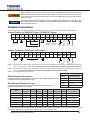
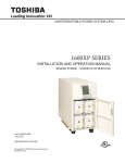
Quick Installation Guide
1600XP Series UPS
Purpose
This Quick Installation Guide (QIG) provides the minimum information needed to connect and startup your 1600 XP UPS. The
complete 1600XP Users Manual and supporting documentation are provided in the accompanying CD (P/N 62908). The selfstarting CD requires a PC with a web browser (e.g Microsoft Explorer) and a PDF file viewer (e.g. Adobe Acrobat Reader).
If requested, a printed manual may be provided at no cost from Toshiba International Corporation. Contact UPS Marketing at
800-231-1412.
NOTE: This QIG is not intended to replace the 1600XP Users Manual.
Toshiba International Corporation reserves the right, without prior notice, to update information, make product changes, or
discontinue any product or service identified in this publication.
Toshiba International Corporation shall not be liable for direct, indirect, special, or consequential damages resulting from the use
of the information contained within this QIG.
QUALIFIED PERSONNEL ONLY
Qualified person is one that has the skills and knowledge relating to the construction, installation, operation, and maintenance
of the electrical equipment and has received safety training on the hazards involved (Refer to the latest edition of NFPA 70E for
additional safety requirements).
Qualified personnel shall:
1.
Have read the entire operation manual.
2.
Be trained and authorized to safely energize, de-energize, ground, lockout and tag circuits and equipment, and clear faults
in accordance with established safety practices.
3.
Be trained in the proper care and use of protective equipment such as safety shoes, rubber gloves, hard hats, safety
glasses, face shields, flash clothing, etc., in accordance with established safety practices.
4.
Be trained in rendering first aid.
5.
Be knowledgeable of batteries and the required handling and maintenance precautions.
For further information on workplace safety visit www.osha.gov.
Misuse of this equipment may result in human injury and equipment damage. In no event will Toshiba Corporation be responsible
or liable for either indirect or consequential damage or injury that may result from the misuse of this equipment.
DO NOT open or mutilate the batteries. Released electrolyte is harmful to the eyes and skin and could also be toxic.
DO NOT dispose of the battery module in a fire. The batteries inside may explode.
To be performed by Qualified Personnel Only:
1.
2.
3.
4.
5.
Verify that the UPS is off and that the power is disconnected from the power source.
Remove watches, rings or other metal objects.
Use tools with insulated handles to prevent inadvertent shorts.
Wear rubber safety gloves and boots.
DO NOT place tools or any metal parts on top of batteries.
Contact with any part of a grounded battery can result in electrical shock.
The likelihood of shock will be reduced if such grounds are removed prior to installation or maintenance.
62909-000
March 2010
1
Inspection/Unpacking
Inspection
Upon receipt of the UPS, an inspection for shipping damage should be performed. Use caution when removing the unit from the
pallet. Refer to labels or documentation attached to packing material.
Unpacking
Check the unit for loose, broken, bent or otherwise damaged parts. If damage has occurred during shipping, keep all original
crating and packing materials for return to the shipping agent. The warranty does not apply to damage incurred during shipping.
Ensure that the rated capacity and the model number specified on the nameplate conform to the order specifications.
Installation Precautions
1.
Install the unit in a well-ventilated location; allow at least 4 inches (10 cm) on all sides for air ventilation and for
maintenance.
2. Install the unit in a stable, level and upright position that is free of excessive vibration.
3. Install the unit where the ambient temperature is within 32 – 104 °F (0 – 40 °C).
4. DO NOT install the UPS in areas that are subject to high humidity.
5. DO NOT install the UPS in areas that allow exposure to direct sunlight.
6. DO NOT install the UPS in areas that allow exposure to high levels of airborne dust, metal particles, or flammable
gases.
7. DO NOT install the UPS in areas near sources of electrical noise. Ensuring a proper earth ground will reduce the effects
of electrical noise and will reduce the potential for electrical shock.
8. DO NOT install the UPS in areas that would allow fluids or any foreign object to get inside the UPS.
9. The UPS generates and can radiate radio-frequency energy during operation. Although RFI noise filters are installed
inside of the unit, there is no guarantee that the UPS will not influence some sensitive devices that are operating near
by. If such interference is experienced, the UPS should be installed farther away from the affected equipment and/or
powered from a different source than that of the affected equipment.
10. After ensuring that all power sources are turned off and isolated in accordance with established lockout/tagout procedures,
connect the power source wiring of the correct voltage to the input terminals of the UPS.
11. Connect the output terminals of the UPS to the load (refer to NEC Article 300 – Wiring Methods and Article 310 –
Conductors For General Wiring). Size the branch circuit conductors in accordance with NEC Table 310.16.
Conductor Routing and Grounding
1.
2.
3.
4.
Use separate metal conduits for routing the input power, output power, and control circuits.
Follow the wire size and tightening torque specifications listed on page 4.
Always ground the unit to reduce the potential for electrical shock and to help reduce electrical noise.
A separate ground cable should be run inside the conduit with the input power, output power, and control circuits.
THE METAL OF CONDUIT IS NOT AN ACCEPTABLE GROUND.
Operating Precautions
1.
The UPS should not be used with a load that has a rated input that is greater than the rated output of the UPS.
2.
DO NOT use the UPS to provide power to motors that require high starting current or with motors that require a long
starting time, such as vacuum cleaners/machine tools (oversizing the UPS for lock rotor current would be required).
3.
DO NOT attempt to disassemble, modify, or repair the UPS. Repairs and servicing should only be performed by Toshiba
Field Service personnel.
4.
Access panels should be removed only by Toshiba Field Service personnel.
5.
Turn the power on only after installing ALL of the covers.
6.
If the UPS should emit smoke, produce an unusual odor, or make sound, turn the power off immediately.
2
1600XP Series Quick Installation Guide
When operating in the inverter mode, placing the breaker in the OFF position will switch the UPS to the
battery backup mode. The output of the UPS will continue uninterrupted to the load. The unit must be
in the bypass mode at the time that the breaker is placed in the OFF position for the UPS to shutdown
power to the load.
Wait at least 5 minutes after an Emergency Power Off (EPO) before resetting the UPS breaker. This
allows the UPS circuitry to fully discharge. The UPS could be damaged if the unit is not fully discharged
before the breaker is reset.
NOTICE
Hardwire Connections
Remove the terminal cover plate on the lower-left back side of the UPS. Follow the directions below in wiring the unit.
Jumper Position for 208V/240V Input, 240/208/120V Output
12
13
14
15
1
2
3
4
5
6
7
8
11
L1
L2
G
X1
X2
N
X3
G
208 COM 240 EPO1 EPO2
120 V
208/240 Vin
120 V
Jumper
position
for 208 V
208 V
16
17
REMOTE1
REMOTE2
16
17
REMOTE1
REMOTE2
Jumper
position
for 240 V
240 V
Jumper Position for 230V Input, 230V Output
1
2
L1 (l) L2 (n)
3
4
5
6
7
8
G
X1
X2
N
X3
G
230 Vin
11
12
13
14
15
EPO1 EPO2
230 V
Note 1 – If AC input power is 208 Vac rated, short terminals 11 and 12 with the provided jumper wire/bus bar. DO NOT jumper terminal 13 to
12 or 11. Factory Setting is 208Vac. Use the jumper wire/bus strip provided by Toshiba. DO NOT add any additional jumpers.
Note 2 – If AC input power is 240 Vac rated, short terminals 12 and 13 with the provided jumper wire/bus bar. DO NOT jumper terminal 11 to
12 or 13. Use the jumper wire/bus strip provided by Toshiba. DO NOT add any additional jumpers.
Note 3 – 8-22 kVA UPSs have a jumper bus bar.
Output Terminal Voltages
Vout
Terminal Lugs
Connect the load to the output terminals according the load voltage requirements. See
the Output Terminal Voltages table to the right.
120 V
X3 - N, X1 - N
208 V
X3 - X2
Wire Size and Tightening Torque
240 V
X3 - X1
230 V
X3 - X1
Output Terminal Connections
Use the following table to select the recommended wire size and terminal lug
tightening torque for I/O wire connections.
Item
Terminal
Number
AWG
3.6 kVA
AWG
6 kVA
AWG
8 kVA
AWG
10 kVA
AWG
14-18 kVA
AWG
22 kVA
Tightening Torque
lb.-in. (N•m)
AC Input Lines
1 and 2
12 (8)
10 (8)
8 (1/0)
6 (1/0)
4 (1/0)
1 (1/0)
14.2 (1.56)
AC Output Lines
4, 5, and 7
12 (8)
10 (8)
8 (1/0)
6 (1/0)
4 (1/0)
1 (1/0)
14.2 (1.56)
AC Output Neutral
6
12 (8)
10 (8)
8 (1/0)
6 (1/0)
4 (1/0)
1 (1/0)
14.2 (1.56)
Ground
3 and 8
12 (8)
10 (8)
8 (1/0)
6 (1/0)
4 (1/0)
1 (1/0)
14.2 (1.56)
EPO Switch
14 and 15
16
16
16
16
16
16
9.0 (0.99)
Remote Switch
16 and 17
16
16
16
16
16
16
9.0 (0.99)
Note: Wire size presented as the recommended size followed by a bold number in () that is the maximum wire size the terminal block can
accommodate. See the manual, page 48, for knock-out hole sizes on the back of each model.
1600XP Series Quick Installation Guide
33
Initial UPS Startup
The first time the UPS is activated after being shipped from the factory, an initialization program will require the
operator to input the following parameters. The UPS display operation is explained in detail on pages 32-62
1. The first screen during the initial startup sequence requires the operator to select the nominal input voltage.
2.
3.
4.
5.
6.
7.
Select from 208V, 230V, or 240V, and press the Write key. If the command has been accepted, the word
“Successful” will appear at the bottom left side of the display.
Repeat the process in step 1 in selecting the Rated Vout.
Repeat the process in step 1 in selecting the Input Frequency.
Use the keypad to type in the current date in the format: Mon 10/05/2009. and press Write.
Use the keypad to type in the current time in 12 hour format: 12:15 PM and press Write.
The Main screen is now displayed. Verify the UPS is in BYPASS mode. The mode (lower right side of the
display) should display Bypass. If it does not display Bypass, press and momentarily hold the STOP button.
With the UPS in bypass mode, cycle power to the UPS as follows:
• At the rear of the UPS switch the main circuit breaker MCCB to OFF.
• Leave the UPS off until the DC bus is safely discharged (approximately 5-10 minutes).
• Restart the UPS by switching the main circuit breaker ON.
The table below summarizes the initialization parameters:
ID
Command
Options
111
Rated Vin
Select from 208V, 230V, or 240V, and press Write.
215
Rated Vout
Select from 208V, 230V, or 240V, and press Write.
141
Input Frequency
Select from 60Hz or 50Hz, and press Write.
634
UPS Date
Input the date in this format: Mon 10/05/2009. and press Write.
635
UPS Time
Input the current time in 12 hour format: 12:15 PM and press Write.
FAQ Sheet
Following are some Frequently Asked Questions concerning installation of the 1600EP Series UPS.
NOTICE
FAQ #1
The batteries for the UPS must be installed while the UPS is energized.
My Output is ~85V.
Problem: Output is wired across the incorrect output terminals. The voltage across terminals 5 – 6(X2 – N) will
be approximately 85V.
Solution: The correct 120V output terminals are 4 – 6 (X1 – N), and 7 – 6 (X3 – N).
FAQ #2
My Output is other than 85, 120, 208 or 240V.
Problem: The Terminal strip jumper may be installed incorrectly for the incoming voltage.
Solution: Check that the Jumper wire/buss strip is installed correctly for the incoming voltage.
Toshiba Contact Information: Toshiba Industrial Division, 13131 West Little York Road, Houston, TX 77041
Tel: US 800-231-1412, Canada 800-872-2192, Mexico 01/800/527-1204
4 4
www.toshiba.com/ind
1600XP Series Quick Installation Guide