1
Argent Terminal Adaptor - User Guide
Version 1.3
Version 1.1
Page 1/29
Telstra Corporation Limited
ACN 051 775 556
Argent Terminal Adaptor - User Guide
The information contained in this document was correct at the time of printing. However, in order to
improve its products, Telstra reserves the right to modify the details in this document at any time and
without warning.
Copyright© 1999 Telstra Corporation Limited
Copyright© 1999 Braintree Communications Pty Ltd
http://www.braintree.com.au
This work is copyright. All rights reserved. Other than for purposes and subject to conditions prescribed
under the Copyright Act, no part of it may in any form or by any means (electronics, mechanical,
photocopying, microcopying, scanning, recording or otherwise) be reproduced, stored in a retrieval
system or transmitted without prior permission from Telstra Corporation Limited and Braintree
Communications Pty Ltd. This document has been developed by Telstra and Braintree for the Telstra
Argent Terminal Adapter.
© Registered Trademark of Telstra Corporation Limited
™ Trademark of Telstra Corporation Limited
Version 1.1
Page 2/29
Telstra Corporation Limited
ACN 051 775 556
Argent Terminal Adaptor - User Guide
Table of Contents
1
INTRODUCTION
5
2
SCOPE
5
3
DESCRIPTION
5
3.1 Application
5
3.2 Definitions
6
3.3 Package Contents
6
3.4 Back Panel
7
3.5 Top Panel Seven Segment Display
8
3.6 ATA Activation Instructions
3.6.1 Prepare position
3.6.2 Connect ATA to NT1
3.6.3 Connect the EFTPOS terminal to ATA
3.6.4 Power-up the ATA
3.6.5 Adjust the Display Orientation of the ATA
3.6.6 Select the Required TEI Number
3.6.7 Observe D-Channel X.25 Call Progress For the First Call
3.6.8 Observe D-Channel X.25 call Progress For the Second Call
3.6.9 Observe the Software Download
3.6.10
Observe for Configuration File Errors
3.6.11
Observe for Failure to Connect
3.6.12
Observe that the ATA is ready and record the service details
3.6.13
Replace the ATA if Faulty on Arrival
3.6.14
Point-to-Point Protocol (PPP) Installation
3.6.15
Installing Dial-Up Network
3.6.16
Configuring Dial-Up Networking (DUN)
3.6.17
V.120 Setup
3.6.18
Connect the EFTPOS terminal
3.6.19
End to end test
9
9
9
9
10
10
10
10
10
11
11
11
12
12
13
15
16
17
17
17
3.7 ATA Maintenance
3.7.1 Check the Seven Segment display
3.7.2 Check that the Power is On
3.7.3 Restart the ATA
3.7.4 Perform a Cold Reboot on the ATA
3.7.5 Test the OnRamp® 2 D-channel X.25 facility
3.7.6 Contact the Service Provider and Replace the ATA
3.7.7 Maintenance by Telstra
3.7.8 Customer Network Management (CNM)
18
18
18
18
18
18
18
19
19
3.8 Warranty
3.8.1 ATA faulty on arrival
3.8.2 ATA under Warranty - with Telstra Service Assurance
3.8.3 ATA under Warranty - without Telstra Service Assurance
3.8.4 ATA out of Warranty - with Telstra Service Assurance
19
19
19
19
20
Version 1.1
Page 3/29
Telstra Corporation Limited
ACN 051 775 556
Argent Terminal Adaptor - User Guide
4
5
6
V.24 SERIAL PORT ‘AT’ COMMANDS
21
4.1 Introduction
21
4.2 ‘AT’ Commands
21
4.3 S register settings
22
POTS TELEPHONE SUPPLEMENTARY FEATURES
23
5.1 Introduction
5.1.1 Abbreviations used in the POTS feature descriptions
23
24
5.2 Telephone Port (POTS) Features
5.2.1 Call Waiting (CW)
5.2.2 Malicious Call Identification (MCID / MCT)
5.2.3 Calling Line Identification Restriction (CLIR or Call Blocking)
5.2.4 Call Line Presentation (CLIP)
5.2.5 Call Forward
5.2.6 Multiple Subscriber Number (MSN)
25
25
25
25
26
27
27
SPECIFICATIONS
Version 1.1
Page 4/29
29
Telstra Corporation Limited
ACN 051 775 556
Argent Terminal Adaptor - User Guide
1 INTRODUCTION
This document is provided as a guide describing the procedures for installation, usage and
maintenance of Telstra’s Argent Terminal Adaptor (ATA).
It is highly recommended that a Telstra qualified technician install this product.
However, if you choose to install the ATA yourself, you will need knowledge of the
operation of Telstra’s Argent service and be familiar with the installation process of
digital terminal adaptors.
The ATA can be used as a normal Terminal Adaptor (TA) or modem, plus it has ports for
an Analogue phone connection (also called POTS -–Plain Old Telephone System). This
user guide describes these services which do not require a specialised knowledge for
installation. An understanding of PC and modem configuration will be an advantage.
Most operating systems such as Microsoft Windows, Unix and Linux are able to connect
to the Serial (V.24) port of the ATA like a modem. Braintree Communications developed
the ATA for Telstra’s Argent network. The ATA continues to improve and the latest user
guide and installation software can be downloaded from Braintree’s Internet Address at
www.braintree.com.au.
2 SCOPE
The instructions in this document should be followed when installing the Argent Terminal
Adaptor.
IMPORTANT NOTE:
1)
You must ensure that OnRamp®2 D-Channel service has been installed, tested and is
operational prior to attempting Argent TA installation.
2)
The ATA can share the S-bus of the OnRamp® 2 D-channel with other devices, but
only if they are configurable for point-to-multipoint operation.
3)
Warranty will be void if the ATA is proved to have been incorrectly installed.
3 DESCRIPTION
3.1 Application
The ATA is an ISDN terminal adaptor that provides a network access for EFTPOS
terminals to communicate with the Financial Host Service Providers via Telstra
OnRamp® 2 D-Channel and Argent services.
It also provides data access for connection to an Internet Service provider (ISP) and
asynchronous data transfer using V.120. The POTS port allows an analogue phone that
would exist on the Public Switched Telephone Network (PSTN) to use the ISDN. The
ATA enables the POTS telephone to be able to take advantage of Telstra supplementary
services like Call Waiting, Call Forward, and others.
Version 1.1
Page 5/29
Telstra Corporation Limited
ACN 051 775 556
Argent Terminal Adaptor - User Guide
3.2 Definitions
The following words, acronyms and abbreviations are referred to in this document.
Term
Definition
ATA
Argent Terminal Adaptor
EFTPOS
Electronic Funds Transfer at Point Of Sale
CPE
Customer Premises Equipment
FFS
Fee For Service
MFFS
Maintenance Fee For Service
NMS
Network Management System
POTS
Plain Old Telephone Service
PPP
Point-to-Point Protocol
TEI
Terminal Endpoint Identifier
3.3 Package Contents
The ATA package
(Telstra Material Number 577/00116)
ATA unit
Power plugpack
Mounting template
Two (2) screws
Category 5 cable fitted with one standard and one keyed RJ45
connector
User Guide (this document)
Warranty card
Table 1: ATA Package Contents
Description
Material Number
Power Plugpack
577/00117
Cat-5 data cable with standard and keyed
RJ45 connectors (2 metres)
577/00118
Table 2: ATA Spare Parts
Version 1.1
Page 6/29
Telstra Corporation Limited
ACN 051 775 556
Argent Terminal Adaptor - User Guide
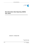
3.4
Back Panel
The ATA contains one analogue EFTPOS port (611 data phone socket), one V.24
(Serial/RS232) data port (DB25 connector), one standard analogue telephone port (RJ45
connector) and one ISDN port (RJ45 keyed connector).
Figure 1: ATA Back Panel
The function for each of the ports is listed below.
Port
Functions
EFTPOS Modem port
Connects to modem enabled EFTPOS Terminal
V.24 / Serial port (RS232)
PPP access to Internet, from Windows, Unix, Mac
V.120 for Asynchronous data, for Cash Registers, Terminals
EFTPOS synchronous access (like the Modem Port)
POTS phone port
Analogue telephone connection to ISDN network
ISDN port
Carries telephone and data from all other ports
Version 1.1
Page 7/29
Telstra Corporation Limited
ACN 051 775 556
Argent Terminal Adaptor - User Guide
3.5 Top Panel Seven Segment Display
The Seven-Segment display consists of lighted segments to display numbers 0-9 plus a
dot. This shows the startup state of the ATA and on-going status of the EFTPOS
connection. Displays do not relate to calls on the POTS port or the V.24 serial port
(except for EFTPOS).
When starting up the ATA, the Seven-Segment display lights up and moves through a
sequence of patterns and numbers. The numbers displayed are steady when the call is
progressing and the configuration downloading normally on the D-channel during startup.
The display flashes a number continuously if call progress encounters an error condition
during startup.
Table 3 provides a list of “startup status codes” that the ATA displays in order of
sequence when the power is being applied, the call is being set up, and the configuration
is being downloaded by the Argent Network Management System (NMS).
Table 4 provides a list of “fault codes” displayed when a fault occurs.
Display
Building Bars
Steady 1
Steady 2
Steady 3
Steady 4
Steady 5
Steady 6
Steady 7
Steady 8
Steady 9
Steady 0
Steady dot
Interpretation
Program decompressing into memory
Power-on test executing. Dot will pulse on/off.
D-channel interface active for EFTPOS
Pre-Configuration in progress, learning identity.
Remote management in progress, configuration.
Software download in progress
Reserved
Reserved
Reserved
Reserved
Reserved
Normal Operation (no fault)
Table 3: ATA Seven Segment Display Start-up Status Codes
Display
Flashing 1
Flashing 2
Flashing 3
Flashing 4
Flashing 5
Flashing 6
Flashing 7
Flashing 8
Flashing 9
Flashing 0
Interpretation
Power up self test fails
ISDN connection down
No carrier on EFTPOS modem port
Data overrun/underrun on Serial V.24 port
No stations responding to polls on EFTPOS port
Last call attempt failed, D-Channel. (X.25 fault or
Argent server or NMS unavailable.)
Not applicable
NMS has no pre-configuration to download
NMS main configuration failure
Not applicable
Table 4: ATA Seven Segment Display Fault Codes
Version 1.1
Page 8/29
Telstra Corporation Limited
ACN 051 775 556
Argent Terminal Adaptor - User Guide
Only the decimal point on the Seven Segment Display is illuminated when the
configuration has been downloaded successfully by the Argent NMS, and the ATA is
functioning correctly with connected EFTPOS terminals responding normally. No other
codes will be displayed on the Seven Segment Display in this mode and the unit can be
assumed to be correctly configured and operational.
If the ATA is commissioned before it is connected to an EFTPOS machine then it will
display a flashing 3 until the EFTPOS machine is connected.
3.6 ATA Activation Instructions
Telstra should supply the following information after the OnRamp® 2 D-Channel service
has been installed and tested.
• Argent EFTPOS service FNN:
FNN =
FxxxxxxxxxxY (Argent Dedicated Service)
FxxxxxxxxxxT (Argent Test Service)
where xxxxxxxxxx is the 10 digit number of the OnRamp® 2 service.
• TEI number (S-Bus D channel address for the ATA. Factory default OnRamp® 2 is
63, Microlink® requires 1. See section 3.6.6 )
• Whether this is a migration from Transend to Argent service.
The steps following can then be followed:
3.6.1
Prepare position
The ATA can be installed either horizontally or vertically. Make sure that it is close to
the OnRamp® 2 NT1 (2 metres) and a 240V outlet and within reach of the EFTPOS
terminal. Avoid placing the unit in direct sunlight or near hot surfaces.
3.6.2
Connect ATA to NT1
Connect the ATA ISDN Port to the OnRamp® 2 NT1 S-Bus using only the supplied
cable. The end marked “Terminal” is keyed to fit into the ATA’s ISDN port. The end
marked “Network” is plugged into the NT1.
3.6.3
Connect the EFTPOS terminal to ATA
Connect the cord from the EFTPOS terminal into the EFTPOS 611 connector on the ATA
back panel. In some cases it may be possible to bypass an existing EFTPOS modem and
go directly into the V.24 modem. Telstra will be able to advise if this is possible, and set
up the ATA from the Management system to accommodate this connection.
Version 1.1
Page 9/29
Telstra Corporation Limited
ACN 051 775 556
Argent Terminal Adaptor - User Guide
3.6.4
Power-up the ATA
Insert the Plugpack connector into the 12VDC socket on the ATA back panel.
Whilst pressing and holding the RST button at the back of the ATA, turn the 240V power
on at the power point. Release the RST button when the display changes to a “C”.
3.6.5
Adjust the Display Orientation of the ATA
The ATA starts with a “C” displayed (for “cold boot”) then progresses to the “Display
Orientation Mode” and you have 3 seconds to press the RST button to change the display
orientation if the unit is wall mounted. An upright “U” symbol indicates correct display
orientation. Mounted on a wall the display should be inverted so the numbers appear in
the correct orientation.
3.6.6
Select the Required TEI Number
After the “Display Orientation Mode” the ATA goes into the “TEI Setting Mode”. The
default TEI is 63 when an ATA is installed for the first time. First, the current TEI is
displayed. Then you have the opportunity to change the TEI if needed. “H” will be
initially displayed indicating the ‘most significant digit’ (MSD) followed by the current
MSD with a decimal point. This is displayed for three seconds during which time the
number can be changed. Then an “L” is displayed followed by the ‘least significant digit’
(LSD) with no decimal point for the next three seconds.
If the TEI number needs to be changed, use the RST button to step through the numbers
to set the required MSD, while the MSD is displayed. Similarly, step through the numbers
for the LSD until the required number is selected. The ATA will then flash the new TEI
and exit the TEI mode.
Another method of setting the TEI is to use a phone on the POTS port and enter
#6#<TEI>#, where <TEI> is the number required (e.g. to program a TEI of 63 press
#6#63#).
3.6.7
Observe D-Channel X.25 Call Progress For the First Call
After exiting the “TEI Numbering Mode” the ATA performs self-test and other internal
functions which take about 90 seconds to complete. Activity during this phase is
indicated by a display of three rising bars. It then automatically makes a D-Channel X.25
call to the factory programmed Argent Pre-configuration NMS number to obtain its IP
address and the X.121 and IP addresses of the main NMS application hosts. During this
process the Seven-Segment Display shows a 3, “Pre-Configuration in Progress”. If for
some reason the ATA is unable to establish an X.25 connection or the connection is
terminated with a non-zero error code (Cause/Diagnostic code), the display will show a
flashing 6 (Last call attempt failed, D-Channel).
3.6.8
Observe D-Channel X.25 call Progress For the Second Call
Version 1.1
Page 10/29
Telstra Corporation Limited
ACN 051 775 556
Argent Terminal Adaptor - User Guide
Next, the ATA makes a new D-Channel X.25 call to the main Argent NMS, to
automatically download its configuration. “Remote Management in Progress” (Display 4)
will be displayed during this process.
3.6.9
Observe the Software Download
The Argent NMS will then make a decision if the ATA requires a new version of
software. If this decision is made the NMS will start downloading the new software
which will take between 3 to 10 minutes. “Software Download in Progress” (Display 5)
will be displayed for the duration of the download. If there is no need to download a new
version of software the NMS will only download the configuration information for the
site.
Do not turn off the ATA or break the connection during a software download.
3.6.10 Observe for Configuration File Errors
During the previous two steps when the ATA makes a call to the NMS to get its
configuration, the ATA may show a flashing 8 (“NMS has no configuration to
download”) or flashing 9 (NMS main configuration failure) on the Seven Segment
Display. This error condition indicates that the configuration files for this specific ATA
are not available. This is probably due to the provisioning cycle not being completed for
the software components. Contact your Service Provider for further information.
3.6.11 Observe for Failure to Connect
During the previous steps when the ATA makes a call to the NMS to get its configuration
the ATA may show a flashing 6 (“Last call attempt failed, D-Channel either X.25 fault or
NMS unavailable.”) on the Seven Segment Display. This indicates that the ATA is
having trouble connecting to the NMS service. Check the ISDN service is currently
active and there are not problems with cable connections. One method of checking is to
use a normal analog telephone to listen for dial tone through the POTS port of the ATA.
If the dial tone exists, the D channel connection should be checked with Austpac Support
Services.
Version 1.1
Page 11/29
Telstra Corporation Limited
ACN 051 775 556
Argent Terminal Adaptor - User Guide
3.6.12 Observe that the ATA is ready and record the service details
When the above steps have completed successfully, and the configuration is downloaded.
There may be a 1-2 minute delay while the ATA activates software, after which the
decimal point on the Seven-Segment Display will be illuminated indicating that the unit is
now ready for EFTPOS transactions. (NOTE: If the EFTPOS terminal is not yet
connected the final display will be a flashing 3 - “No carrier from EFTPOS modem”).
After observing this write the following information onto the sticker at the bottom of the
unit:
• Argent EFTPOS service FNN:
FNN =
FxxxxxxxxxxY (Argent Dedicated Service)
FxxxxxxxxxxT (Argent Test Service)
where xxxxxxxxxx is the 10 digit number of the OnRamp® 2 service.
• TEI = xx
• ATA Fault Reporting Number = Service Provider Helpdesk number
• Date of Purchase = dd/mm/yy
You must call your own Help Desk fault reporting number for any difficulties. This
number is supplied with the EFTPOS terminal.
3.6.13 Replace the ATA if Faulty on Arrival
If the ATA is faulty on arrival, see section 3.8 for warranty instructions.
Version 1.1
Page 12/29
Telstra Corporation Limited
ACN 051 775 556
Argent Terminal Adaptor - User Guide
3.6.14 Point-to-Point Protocol (PPP) Installation
PPP is used to connect to Internet or other ISDN TAs using the common Windows, Unix,
Macintosh interfaces. Most commonly, it is used for Internet access.
PPP over a OnRamp® 2 B-channel can be invoked via the V.24 Serial port, from a
Windows 95 PC or similar, by setting up Dial-up networking similar to the configuration
of a standard modem.
To use PPP, set up your computer as you would for connecting a standard modem - with
no parity, 8 data bits and one stop bit, (ie N, 8,1).
The Argent Terminal adaptor connects to a terminal or computer with a standard modem
cable. Plug the D25 male connector into the V.24 / RS232 Serial port on the ATA using a
standard straight through modem cable.
Connecting communications equipment, like a modem or router, to the ATA’s V.24 port
would require a crossover cable.
Follow the steps below to install the ATA as a Standard Modem
Check Braintree’s website (www.braintree.com.au) for the latest information on
installation.
1. Click on START
2. Click on Settings
3. Click on Control Panel
4. Double Click on Modem
Version 1.1
Page 13/29
Telstra Corporation Limited
ACN 051 775 556
Argent Terminal Adaptor - User Guide
5. Click on Add
6. Tick Don’t detect my modem; I will select from list
7. Click on Next
8. Select Standard Modem Types – Standard 33600 bps Modem
9. Click on Next
10. Select the Communications port to which the ATA Modem is attached
Version 1.1
Page 14/29
Telstra Corporation Limited
ACN 051 775 556
Argent Terminal Adaptor - User Guide
11. Click on Finish
12. Click on Properties
13. Set Maximum speed to 115200
14. Click on Close
Your ATA Modem is now installed
3.6.15 Installing Dial-Up Network
To Install Dial-Up Networking (DUN) and TCP/IP please refer to your Microsoft
Installation Guide or your Internet Service Provider (ISP) for the latest configuration
information.
Version 1.1
Page 15/29
Telstra Corporation Limited
ACN 051 775 556
Argent Terminal Adaptor - User Guide
3.6.16 Configuring Dial-Up Networking (DUN)
1. Open My Computer from your Desktop
2. Open Dial-Up Networking
3. Double click on Make New Connection
4. Type in the name of your ISP
5. Select a device (Standard 33600 bps Modem)
6. Click Next
7. Type in the area code and telephone number of ISP dial-up number
Version 1.1
Page 16/29
Telstra Corporation Limited
ACN 051 775 556
Argent Terminal Adaptor - User Guide
8. Click Next
10. Click Finish
3.6.17 V.120 Setup
V.120 allows a device using a serial port to connect to another remote device using a
serial port. The V.120 carries the data transparently like a cable. V.120 handles transport
mechanisms without involving the end devices or terminals.
This protocol is ideal for legacy equipment that previously required a modem, or leased
line for connection. Some applications would be connection to Cash Registers,
monitoring equipment, Bar Code readers, serial printers, Unix, Macintosh, Windows and
DOS based PCs.
V.120 requires the devices on the local and remote ends of the ISDN connection to be set
up exactly the same. Both ends must use the same number of data bits, parity, speed and
stop bits. Currently the most popular setting for asynchronous serial connections are no
parity, 8 data bits and one stop bit, (ie N, 8,1).
To set up V.120, use a Terminal Communications program (e.g. Microsoft ™
Hyperterminal) and connect to the V.24 Port of the ATA. Use the following command to
change to V.120.
ATS71=2 ↵
Any AT command will cause the ATA to autobaud changing the speed or baud rate to
match the speed of the AT command.
3.6.18 Connect the EFTPOS terminal
After observing that the ATA is operational, test the service using your CPE. If not
already done, connect the EFTPOS terminal. The Display should change to a flashing 5
(carrier detected but no terminal responding) then to just the decimal point when the
terminal begins responding normally.
Important Note: When the V.24 port is set up by Telstra remote management system to
run EFTPOS, it can not be used for PPP or V.120.
3.6.19 End to end test
Contact your Service Provider to arrange for an end to end test.
Version 1.1
Page 17/29
Telstra Corporation Limited
ACN 051 775 556
Argent Terminal Adaptor - User Guide
3.7 ATA Maintenance
In the case where the Argent TA fails to operate, contact your Service Provider for
assistance.
3.7.1
Check the Seven Segment display
Check the ATA Seven Segment Display for indication of possible fault conditions. The
normal running state is Decimal point only illuminated.
3.7.2
Check that the Power is On
Check to see that the power is “on” and that all the physical connections are in place and
correctly located.
3.7.3
Restart the ATA
Switching off the power supply for 5 seconds then switching it on again will reboot the
ATA. The reboot takes about 90 seconds. Do NOT press the RST button as this has
other functions.
3.7.4
Perform a Cold Reboot on the ATA
If performing a restart (described in section 3.6.3) does not restore the service, perform a
cold reboot. To do this, turn off the power supply, then press and hold the RST button at
the back of the ATA and turn power back on. Check the display orientation and that the
correct TEI is displayed. The configuration info and, if necessary, the software will
reload into the ATA as in the activation instructions. Display orientation and the TEI
number will be preserved during the cold reboot.
3.7.5
Test the OnRamp® 2 D-channel X.25 facility
If for some reason the ATA is unable to establish an X.25 connection, the display will
show a flashing 6 (Last call attempt failed, D-Channel). If this happens contact the
Service Provider for assistance on testing the OnRamp® 2 D-Channel X.25 facility.
3.7.6
Contact the Service Provider and Replace the ATA
If the fault cannot be rectified, contact the Service Provider and inform them of the
outcome of the test. The ATA may need to be replaced.
If the ATA is still under warranty, return it to the place of purchase for a replacement. If
the product is out of warranty then a new ATA will need to be purchased.
Version 1.1
Page 18/29
Telstra Corporation Limited
ACN 051 775 556
Argent Terminal Adaptor - User Guide
3.7.7
Maintenance by Telstra
Telstra Service Assurance contracts are available for the ATA which can cover labour
and parts for maintenance activity during contracted hours (please note that some
exclusions do apply eg unfair wear & tear). The customer should contact their Service
Provider to apply for a Telstra Service Assurance contract.
Telstra can provide maintenance to uncontracted customers however “Maintenance Fee
For Service” charges will apply.
Contact your Service Provider for assistance if they suspect the ATA is faulty.
3.7.8
Customer Network Management (CNM)
In future the Customer Network Management (CNM) facility will be able to control and
monitor the ATA. Contact Telstra for further details on CNM.
3.8 Warranty
The ATA is covered by a one-year warranty period from the date of purchase. The date of
purchase is the date that the customer receives the ATA from Telstra.
If the ATA fault is found to be external and visible, such as a broken connection cable or
a faulty power plugpack, the customer is required to replace them with the Telstra
approved components (refer to section 3.3).
Refer to the warranty card for details on the Warranty Conditions.
The general warranty procedures are described in the sections below.
3.8.1
ATA faulty on arrival
If the ATA is found to be faulty on installation it is your responsibility to return the
complete package to the place of purchase for replacement.
3.8.2
ATA under Warranty - with Telstra Service Assurance
If the ATA is found to be faulty and the customer has Service Assurance, the ATA will be
replaced by Telstra.
3.8.3
ATA under Warranty - without Telstra Service Assurance
If the ATA, under normal use, fails to operate during the warranty period then it is your
responsibility to return the complete package to the place of purchase for replacement.
Table 1 shows contents of an ATA complete package.
If the ATA was purchased through a Service Provider, you should contact that service
provider for replacement procedures.
If the ATA was purchased directly from Telstra, then Telstra can replace the faulty ATA
package with an ATA package from Telstra stores, however Maintenance Fee-ForService charges will apply for the site visit and labour.
Version 1.1
Page 19/29
Telstra Corporation Limited
ACN 051 775 556
Argent Terminal Adaptor - User Guide
3.8.4
ATA out of Warranty - with Telstra Service Assurance
If an ATA, which is out of warranty, is found to be faulty and you have a Service
Assurance contract, Telstra will replace the complete ATA package free of charge (if it
cannot be repaired on site).
Version 1.1
Page 20/29
Telstra Corporation Limited
ACN 051 775 556
Argent Terminal Adaptor - User Guide
4 V.24 SERIAL PORT ‘AT’ COMMANDS
4.1
Introduction
The Argent Terminal Adaptor (ATA) is an ISDN device with powerful features
for interconnection. While the primary purpose of Argent is the delivery of
transactions to centralised hosts, the ATA extends the functionality of the ISDN
line to carry this service.
‘AT’ commands refer to a set of instructions, which can be sent to the ATA to
control local features. The POTS (Plain Old Telephone System) port and V.24
(RS232) serial port can be controlled with a simple set of ‘Attention’ (AT)
commands.
4.2 ‘AT’ Commands
AT
A
&C
D
&D
E
&F
H
I
O
Q
Version 1.1
Page 21/29
Description
Answers an incoming call on the B channel
Carrier Detect (CD) control
AT&C0 forces carrier on at all times
AT&C1 (default) follows the state of carrier on the remote host system.
Is raised after connection.
AT&C2 carrier drops temporarily after a disconnect, but remains on at all
other times.
Dial a remote device. eg ATD6173344 5566
Allows characters {T P 0-9 * # <space> ,}
ATDT<number>, ATDP<number>, ATD<number>
Data Terminal Ready (DTR) Control
AT&D0 Ignore DTR from the Terminal.
AT&D1 ATA will enter command state whenever DTR goes high to low.
AT&D2 (default) Hang up any current call and prepare to accept
commands from the terminal.
Echo
ATE0 Echo off, disables reflecting AT command character back to the
terminal.
ATE1 (default) Echo on. Any received AT command character is sent
back to the terminal.
Factory Default
AT&F Restore all settings back to factory default.
Hang Up
ATH Hang up on the current data call.
Information
ATI return the identification information of the ATA
ATI9 returns the plug and play identifier
Go On-Line
ATO return from command state to the on-line data transfer state.
Quiet Mode
Telstra Corporation Limited
ACN 051 775 556
Argent Terminal Adaptor - User Guide
AT
\Q
%R
%S
Sn?
Sn=
\T
V
%V
&V
&W
Z
+++
Description
ATQ0 (default) Enable result codes output to the terminal.
ATQ1 Disables result codes to the terminal.
ATQ2 Disable result code in answer mode only.
Flow Control
AT\Q0 disables flow control
AT\Q1 enables XON/XOFF software flow control
AT\Q3 (default) enables RTS/CTS hardware flow control
Read all S registers
AT%R Read all the S registers
Serial Number
AT%S Read the ATA serial number
Read S register value
eg ATS51? Retrieves the telephone number
Write S register value
eg ATS51=6173344 5566
Idle Timeout
Time before the link will hang up the line if no data on the connection.
AT\T2 sets up the timer to hang up after 2 minutes idle time
AT\T0 disables the idle timer so it will not cause a hang up
Idle Timeout can be set in minutes with valid values of 0 to 255.
Result code format
ATV0 All results returned in short form
ATV1 (default) results returned in long form
ATA version number can only be read.
AT%V displays the version number of the software in the ATA
Display current configuration
Shows all the current parameters
Save current configuration
AT&W This will store the parameters even if the ATA is turned off
Reset
ATZ resets the ATA without changing the configuration. Current calls
would be lost.
Enter Command Mode
+++ must be a half second of no data actvity before and after “+++”.
4.3 S register settings
Register
S0
S51
Version 1.1
Page 22/29
Description
Auto Answer number of rings
ATS0=0 (default) disables answering incoming data calls
ATS0=n where n is a value 0 to 255 rings
ATA Telephone Number
ATS51=6173344 5566 store the phone number to present in calls. The
other party on the line will see this number as your number. This number
must be one of the numbers issued on this connection by Telstra. MSN
Telstra Corporation Limited
ACN 051 775 556
Argent Terminal Adaptor - User Guide
Register
S59
S60
S65
S67
S71
S75
S92
Description
allows multiple phone numbers on an ISDN service.
ISDN connection status can only be read
ATS59? Returns 0 for connection not synchronised to Telstra network
ATS59? Returns 1 for connection ready for calls.
B Channel Data Rate
ATS60=56 data rate set to 56kbps for international calls
ATS60=64 (default) data rate set to 64kbps calls within Australia
Voice telephone number logged for an incoming voice call, can only be
read.
ATS65?
Data telephone number logged for an incoming data call, can only be
read.
ATS67?
Protocol on the data port
ATS71=1 (default) PPP (Internet) asynchronous to synchronous
conversion
ATS71=2 V.120
Answer call delay
ATS75=0 (default) no delay after answering a call
ATS75=1 Two second delay should be enabled for Windows NT.
Subaddress
ATS92=n where n is a sub-address value. Allows multiple devices using
the same phone number to only recognise calls with a matching
subaddress while they are all attached to the same ISDN line.
5 POTS TELEPHONE SUPPLEMENTARY FEATURES
5.1 Introduction
Supplementary services for ISDN control the switching of calls and how you manage
calls. Forwarding an incoming call to another phone number is one example of
controlling calls through the features of the POTS (Plain Old Telephone System) on the
ATA interacting with the OnRamp® 2 service for voice calls. You require an analogue
tone phone connected to the POTS port of the ATA to initiate the supplementary services.
Some supplementary services, such as MSN (Multiple Subscriber Number), can be set up
with the use of the ‘AT’ commands described in section 4. This section describes the
customer commands to control calls through the telephone port of the ATA.
These features provide the Telstra Easycall® functionality via the ATA on to OnRamp®
2 service. New features may be added from time to time and the Easycall® operation
guide describes functionality of services. More information on the Easycall® features
can currently found at the Telstra website (http://www.telstra.com.au) or from your
Telstra Customer Service centre.
To simplify the instructions to operate each feature abbreviations are shown here for each
step of the procedure. These abbreviations are used to describe the actions required from
an analogue tone phone to initiate a supplementary service.
Version 1.1
Page 23/29
Telstra Corporation Limited
ACN 051 775 556
Argent Terminal Adaptor - User Guide
5.1.1
Abbreviations used in the POTS feature descriptions
[...]
DN
DT
OH
RH
RR
RSP
Version 1.1
Page 24/29
Square brackets indicate that the enclosed item is optional
Destination number
Dial Tone
Off Hook
Replace Handset when condition detected by ATA
Recall signal from telephone
Network Responds with confirmation tone
Telstra Corporation Limited
ACN 051 775 556
Argent Terminal Adaptor - User Guide
5.2 Telephone Port (POTS) Features
5.2.1
Call Waiting (CW)
Call Waiting is an Easycall ™ feature so the customer can detect the presence of another
call, while a call is in progress.
a
b
c
5.2.2
d
Turn Call Waiting on:
Turn Call Waiting off:
Check if CW is enabled or disabled (double tone
indicates that CW is enabled; triple tone indicates
that CW is disabled)
To release the current call and accept the waiting call
e
f
g
h
To hold the current call and accept the waiting call
To alternate between the two parties
To release current call and connect to call on hold
To reject the waiting call (Fend Off)
OH DT * 43 # RSP RH
OH DT # 43 # RSP RH
OH DT *#43# RSP RH
RH (Ring telephone) OH
or RR DT 1
RR DT 2
RR DT 2
RR DT 1
RR DT 0
Malicious Call Identification (MCID / MCT)
Malicious Call Identification allows the customer to request the network to trace
malicious calls on a call by call basis.
a
b
5.2.3
To set Malicious Call Trace during the call
To set Malicious Call Trace up to 60 seconds after
the caller has released the port
RR DT * 39 # [RH]
RR DT * 39 # RH
Calling Line Identification Restriction (CLIR or Call Blocking)
Calling Line Identification Restriction, also called Call Blocking, is a service offered to
the calling party to prevent presentation of the calling party's number. The phone number
of the ATA can be restricted from being viewed at the remote end. In order for the ATA
to present a phone number, it must be entered using the ‘AT’ Command (section 4.2).
a
b
c
To restrict presentation of CLI on a call by call basis
(Note 1)
To allow presentation of CLI on a call by call basis
(Note 1)
Check if CLIR is enabled or disabled (double tone
indicates that CLIR is enabled; triple tone indicates
that CLIR is disabled)
OH DT 1831 DN or
OH DT ##31# RH
OH DT 1832 DN or
OH DT **31# RH
OH DT **#31# RH
Note 1:
The dial number prefix (i.e. 1831 or 1832) is required for every call that the
customer wishes to change (override) the network default status of CLIR.
Version 1.1
Page 25/29
Telstra Corporation Limited
ACN 051 775 556
Argent Terminal Adaptor - User Guide
If you do not have access to a computer, you can enable CLIR on a
permanent basis using the following handset commands:
5.2.4
a
Enable CLIR for the port to which the handset is
connected
OH DT #8#1# RH
b
Disable CLIR for the port to which the handset is
connected
OH DT #8#0# RH
c
Check if CLIR is enabled or disabled (double tone
indicates that CLIR is enabled; triple tone indicates that
CLIR is disabled)
OH DT #8#*# RH
Call Line Presentation (CLIP)
When CLIR is not in effect, the incoming call’s telephone number is stored in register
S65 for Voice (telephone) calls and S67 for Data calls (see section 4.3) will be presented
by the remote end initiating the call.
Version 1.1
Page 26/29
Telstra Corporation Limited
ACN 051 775 556
Argent Terminal Adaptor - User Guide
5.2.5
Call Forward
Call forward allows calls to be forwarded to any other telephone including mobiles either
immediately, when busy or if the call is not answered.
5.2.5.1 Call Forward Immediate or Unconditional
Call Forward Immediate also called Call Forward Unconditional (CFU) will direct all
incoming phone calls to another phone until the feature is turned off.
a
To turn Call Forward Immediate (Variable Number) ON.
OH * 21 DN # RH
b
To turn Call Forward Immediate (Variable or Fixed
Number) OFF.
OH # 21 # RH
c
To check if Call Forward Immediate is ON or OFF
OH * # 21 # RSP RH
5.2.5.2 Call Forward On Busy
Call Forward On Busy (CFB) will direct a phone calls to another phone when the line is in use.
a
To turn Call Forward Busy (Variable Number) ON.
OH * 24 DN # RH
b
To turn Call Forward Busy (Variable Number) OFF.
OH # 24 # RH
c
To check if Call Forward (Variable Number) is ON or
OFF.
OH * # 24 # RSP RH
5.2.5.3 Call Forward No Answer
Call Forward No Answer or Call Forward No Reply (CFNR) will direct a phone calls to another phone
when the call rings unanswered.
5.2.6
a
To turn Call Forward No Answer (Variable Number) ON.
OH * 61 DN # RH
b
To turn Call Forward No Answer (Variable Number)
OFF.
OH # 61 # RH
c
To check if Call Forward (Variable Number) is ON or
OFF.
OH * # 61 # RSP RH
Multiple Subscriber Number (MSN)
Usually two telephone numbers are automatically assigned to an OnRamp service.
Before an MSN number is entered into the AT command registers on the ATA, phoning
any subscribed number from another phone service will make an attached phone ring. It
is possible to have up to eight phone numbers on a single OnRamp service by requesting
them from Telstra. The ATA picks up all phone calls unless a specific number is set up
for MSN in the ATA for exclusive pick up. Exclusive pick up would be used when the
ATA is meant to respond to calls on a different phone number to another device on the
same OnRamp service.
Version 1.1
Page 27/29
Telstra Corporation Limited
ACN 051 775 556
Argent Terminal Adaptor - User Guide
All voice phone calls and data calls will be answered if a telephone number is not entered
into the AT command registers. Once an MSN telephone number is entered, the ATA
will use this number and only receive calls received for this specific telephone number.
All data calls and normal voice calls will only be recognised by the ATA if the phone
number matches the number stored in the ATA. The ATA can distinguish if the remote
device has sent the call as a data call or a voice call (modems / faxes attached to the
POTS port are treated like voice calls). Data calls are directed to the V.24 / RS232 port
and voice calls are assigned to the POTS port.
Usually calls are charged to the primary number for billing purposes. A different
telephone number can be can be used for charging purposes and then calls assigned to this
number would usually appear separately on the same bill. The telephone number used
must be stored in the ATA and selected using an abbreviated dialling sequence at the time
of dialling. This facility could be used to distinguish between business and home calls.
Equipment with Call Line Identification (CLI) capabilities will only see the primary
phone number. The exchange will only pass on the primary number regardless of which
number is offered to the exchange.
If an invalid phone number is stored in the ATA for the MSN feature then the exchange
will assume the primary number for the phone call, but incoming calls WILL NOT be
recognised by the ATA.
Setting the MSN Telephone Number from Phone Handset on the POTS port can be
accomplished with by entering
a
Setting Telephone Number from Phone Handset on the
POTS port. (Note 2)
OH DT #1# [telephone
number] # RH
Note 2:
The [telephone number] should be replaced with one of the telephone numbers
assigned for your service and is not optional (eg #1#0332551234#).
The ATA’s MSN phone number can also be entered using the AT command shown in
section4.2 for the register S51.
Version 1.1
Page 28/29
Telstra Corporation Limited
ACN 051 775 556