1
WG IBT-5
Basic Rate Access
ISDN Tester
BN 7522/10, BN 7522/20 and BN 7522/70
Series CE ...
Software version 3.01
Operating Manual
Please direct all inquiries to your
local Wandel & Goltermann sales
company. The addresses are given at
the end of this handbook.
Wandel & Goltermann GmbH & Co.
Elektronische Meβtechnik
Mühleweg 5, D-72800 Eningen u. A.
1997
Author: Franck BERNARD
Order no.: 7522/98.21
Edition: 05/97.12, CE ...
Previous editions:
04/97.03, CC ...
03/96.12, CA ...
02/96.09, CA ...
01/96.08, CA ...
Subject to change without prior notice.
The product names mentioned herein are used for identification
purposes only, and may be trademarks and/or registered trademarks
of their respective companies.
Printed in U.K.
Prior warning!
An 'NT Simulation' option is now available. This option is compatible with IBT-5
instruments of the CE series or more recent equipped with software version 3.01
and an accu-pack.
U and S0 interfaces must not be connected simultaneously.
Disconnect the network interface before opening the instrument.
Now that you have received your IBT-5, you should register your warranty.
PLEASE FILL OUT THE WARRANTY FORM AT THE END OF THIS MANUAL
AND FAX OR MAIL IT TO WANDEL & GOLTERMANN.
This will help us to keep you informed about future instrument upgrades, etc.
Introduction
With your purchase of the IBT-5, you have obtained an easy-to-use, robust and
compact tool for intensive and daily measurement on the ISDN basic rate access.
The IBT-5 is designed to reduce the time taken to install ISDN lines and
equipment. As easy to use as a telephone, it also enables rapid diagnostics of the
line under test. The IBT-5 is always ready for use thanks to its dual power supply
mode. It can be powered from the tested access or through its rechargeable
batteries.
You will see that the IBT-5 is a solid investment for the future. ISDN is subject to
constant development; new protocols and applications (or simple improvements to
existing IBT-5 features) can be loaded by an easy software update facility.
Additional information on the IBT-5 application or on other IBT family products can
also be requested from your local representative. A list of these representatives is
found at the end of this manual.
IBT-5 User Manual
Product Description
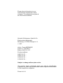
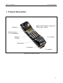
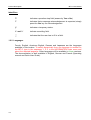
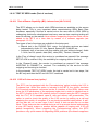
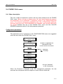
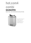
1. Product Description
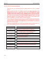
LEDs: network power supply and
ISDN Layer 1 status
Earpiece
Back-lit screen,
2 x 16 characters
Keypad,
16 keys
S / U switch
Microphone
S interface
U interface
Fig. 1-1: IBT-5 general overview
1-1
Product Description
IBT-5 User Manual
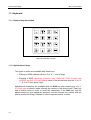
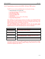
1.1 Keyboard
1.1.1 General key description
Fig. 1-2: Keyboard overview
1.1.2 Alphanumeric keys
Two types of action are available with these keys:
• Editing an ISDN address with the '0' to '9', '*' and '#' keys,
• Entering a SPID (American protocols only: DMS-100, AT&T Custom and
N-ISDN), an NUI, X.25 call data or name in the phone book with the '0' to '9',
'*', '#', A or Z and 'space' keys.
Alphabetical characters are available with the Shift key when entering an NUI or
X.25 call data or directly when entering the names in the phone book. Each key
has a relative timer in order to scroll the characters: if the Shift key and the
alphanumeric key are maintained pressed, it scrolls through the number and the
letters (circular scrolling). Release to select required number or letter.
1-2
IBT-5 User Manual
Product Description
1.1.3 The Yes key
This contextual key has the following actions:
•
•
•
•
•
Switch on the instrument (when battery-operated),
Enter a menu,
Validate a choice,
Give a positive answer,
Validate a field or a parameter.
1.1.4 The No key
This contextual key has the following actions:
• Switch off the instrument (when battery-operated), by pressing the key for 3
seconds,
• Return to the previous user interaction,
• Unvalidate a choice,
• Give a negative answer,
• Interrupt a current measurement or a call and return to the last parameter
entry.
1.1.5 The Clr key (Clear)
This contextual key has the following actions:
•
•
•
•
Delete a character or all characters of a field when used with the Shift key,
Return to the main menu,
Interrupt a current measurement or a call,
Unvalidate a choice.
1.1.6 The Shift key
This key enables access to the '#', '*', 'space' (when used with the '1' key) and to
the alphabetical characters. The activation of the Shift key is sequential and
simultaneous.
The Shift key is used as a Recall function when simultaneously pressed with the
Yes key. It can also be used to activate or deactivate the backlighting of the
screen if pressed simultaneously with the '0' key.
1-3
Product Description
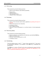
1.1.7 The
IBT-5 User Manual
key
This key is used to scroll menus, parameters or values (left direction). If used
simultaneously with the Shift key, it gives access to the '*' key.
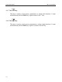
1.1.8 The
key
This key is used to scroll menus, parameters or values (right direction). If used
simultaneously with the Shift key, it gives to access to the '#' key.
1-4
IBT-5 User Manual
Product Description
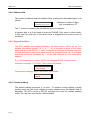
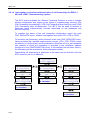
1.2 Display
1.2.1 General description
All fields are displayed with a maximum size of 2 lines of 16 digits each.
Fig. 1-3: User interface overview
Users can activate or deactivate the backlighting of the screen by simultaneously
activating the Shift and '0' keys.
Important note: For reasons relating to power consumption, the backlight
should not activated in restricted mode (LED 'P' red).
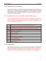
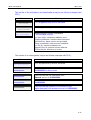
When keying in an address, if the field length exceeds 15 digits, only the current
part of the field is displayed.
For example if the 'Own Address' field is '12345678901234567890123456', the
display indicates the following, depending on the location of the cursor:
The first digit is visible
OWN ADDRESS
12345678901234
The last digit is visible
OWN ADDRESS
567890123456__
1-5
Product Description
IBT-5 User Manual
Identifiers:
'?'
indicates a question step field (answer by Yes or No).
'!'
indicates that a message acknowledgement is expected, simply
press the Yes key for acknowledgement.
'∞ '
indicates a temporary status.
'' and ' '
indicate a scrolling field.
'_'
indicates that the user has to fill in a field.
1.2.2 Languages
French, English, American English, German and Japanese are the languages
available in this version. To switch dynamically from one language to another on
the IBT-5, type in the sequence '1 2 3' in the INFORMATION main menu and
select the required language. Other languages will be available in future versions.
The documentation is also available in English, German and French (Operating
manual and Quick User Guide).
1-6
IBT-5 User Manual
Product Description
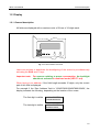
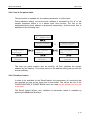
1.3 Power supply
1.3.1 Operating mode
Three operating modes are available on the instrument:
• Connection to the network supplying power for the S0 and U interfaces. The
IBT-5 functions without rechargeable batteries on this type of bus (normal
and restricted mode).
• Connection to the network which does not provide the power supply at both
S0 and U interfaces: the instrument is internally powered through batteries
(option) and has an autonomy of at least 8 hours. The batteries can be
recharged after and during measurements through a specific charger.
• Connection to an ISDN equipment with NT simulation (option): the
instrument is powered by the accu-pack (option).
The instrument recognizes automatically if it is powered from the tested access or
not.
The IBT-5 is compatible with PS1 and PS2.
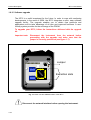
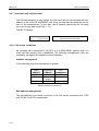
1.3.2 Recharging the batteries in the accu-pack
Users are informed of battery rundown half-an-hour before the automatic
shutdown of the IBT-5. When the LEDs flash orange for 2 seconds in every 60, it
means that the charger should be plugged in so that the test sequence in progress
can be completed.
The LEDs on the rechargeable batteries inform the user when the charger is
connected and when a voltage is present (green LED) and indicate the charging
activity (red LED on: charging, red LED off: charging finished).
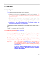
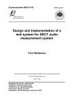
Important:
After a full discharge (red LED off), the 'Reset' button on
the rechargeable batteries in the accu-pack must be
pressed with a pointed tool after connecting the charger
(see figure 1-4).
As with any NiMH rechargeable battery, one or two charge
and discharge cycle(s) should be run in order to achieve
maximum operating time.
1-7
Product Description
IBT-5 User Manual
Reset
Green LED: charger connected
Red LED: charging in progress
Fig. 1-4: Recharging the batteries
1.3.3 Battery characteristics
Autonomy .........................................................8 hours minimum on the S interface
Recharging time ...........................................................................3 hours maximum
Type of batteries.......................................................................... NiMH / 1800 mAH
Emission ........... complies with EN 50081.1, Generic emission standard - Jan 1992
Immunity ........... complies with EN 50082.1, Generic immunity standard - Jan 1992
The charger/batteries interface operates on SELV (Safety Extra Low Voltage).
When using the external battery charger, the charger must be immediately
identifiable and easily reached. The charger plug is used as a primary cut-out
device.
1-8
IBT-5 User Manual
Product Description
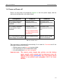
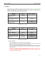
1.4 Power on/Power off
Power on and power off procedures depend on the bus power supply and the
instrument configuration (see table below).
Configuration
Power on
Power off
IBT-5 without batteries/
remote power supply
available
Automatic when
connected to the bus
Automatic when
disconnected from the
bus
IBT-5 battery-operated/
remote power supply
available
Automatic when
connected to the bus
Automatic once
disconnected from the
bus
Manual: press the Yes
key when disconnected
from the bus
IBT-5 with batteries/ remote Manual: press the Yes
power supply not available key
Manual: press the No
key for 3 seconds
Tab. 1-1: Power on/off
The instrument is switched off automatically if not used for 5 minutes and if the
following conditions are fullfilled:
• Remote power supply by bus is not provided,
• The instrument is not in LOOP BOX mode,
• No call established or no test in progress.
Important note: The remote power supply has priority over the battery
power supply, which means that the instrument uses the
battery power supply (accu-pack) only if the remote power
supply is not present (see paragraph 2.2.2.1 for more
details).
1-9
Product Description
IBT-5 User Manual
1.5 Reset Procedures
The IBT-5 has a software reset procedure which retains the configuration if the
Yes and '0' keys are pressed simultaneously.
To reset the configuration to the default values, the RESET field has to be
validated in the CONFIGURATION menu.
1-10
IBT-5 User Manual
Product Description
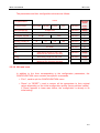
1.6 LEDs
The IBT-5 has two LEDs located above the keyboard. The Power supply LED is
marked with the letter 'P'; the LED relating to the L1 Status is marked with the
letter 'S'. The LEDs have the following meanings:
Stimulus
LED 'P'
LED 'P' colour
No remote power
detected
LED off
-
Remote power detected
normal mode
LED on
Green
Remote power detected
restricted mode
LED on
Red
Tab. 1-2: LED 'P' meaning
Stimulus
LED 'S'
LED 'S' colour
Layer 1 activation
pending*
Slow blinking
Green
Layer 1 activated
LED on
Green
Alerting (incoming calls)
Blinking 1-1
1 Green-1 Red
Bit error alarm during a
BER test
LED on for
3 seconds
Red
Tab. 1-3: LED 'S' meaning
*
For the U interface:
- Layer 1 is established on the U interface, not on the S interface.
- Some public switches do not provide instantaneous activation. In this case, the user must
wait until the LED 'S' stops blinking before running a test (LED lit).
- In case of a defect, some public switches turn the remote power off and on, and ask for a
loop. In this case, the IBT-5 provides the information via the red LED 'S' then restarts the
activation process.
For IBT-5s equipped with rechargeable batteries (option possible from
CC series onwards): If the LEDs flash orange for 2 seconds in every 60, the
charger should be plugged in.
1-11
Product Description
IBT-5 User Manual
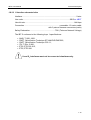
1.7 Buzzer
The buzzer is used to signal events to the user. These events are organized in
three classes depending on their priority:
1
Test errors: low-pitched long sound
2
Key not allowed: low-pitched medium sound
3
Ready state and validation acknowledgment: high-pitched brief sound
The SOUND SIGNS configuration parameter is used to select the event classes to
be indicated by the buzzer.
1-12
IBT-5 User Manual
Product Description
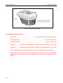
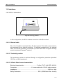
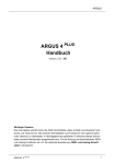
1.8 Interfaces
1.8.1 IBT-5 / S0 interface
WGIBT-5 ISDNButtset
Made in UK
BN 7522
Fig. 1-5: View of S0 interface
In this configuration, the IBT-5 enables connection at the S0 interface.
1.8.1.1 External cable
The 1.5 m S0 cable is terminated by a RJ-45 connector. This cable is connected to
the instrument via an internal connector. To facilitate replacement of the external
cable, the internal connector is accessed by a hatch and uses an original blocking
system (registered Depaepe© system).
1.8.1.2 Terminating resistor
The terminating resistor is switched through a configuration parameter (standard
100 Ohm or High impedance).
1.8.1.3 S0 Basic Rate Access characteristics
Electrical characteristics .....................................To Rec. ITU-T I.430, ETS 300 012
Connection ........................................ 1.5 meter cable with 1 RJ-45 male connector
Impedance........................................................................................100 Ohm / high
Safety Declaration ................................................ SELV (ISDN Basic Rate Access)
1-13
Product Description
IBT-5 User Manual
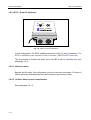
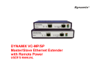
1.8.2 IBT-5 / S0 and U interfaces
S0
U0
WGIBT-5 ISDNButtset
M ade in UK
BN 7522
Fig. 1-6: View of S0 and U interfaces
In this configuration, the IBT-5 enables connection at the S0 and U interfaces. The
IBT-5 is available in two versions for the U interface - 2B1Q or 4B3T line code.
The S0 interface is exactly the same as for the IBT-5 with S0 interface only (see
paragraph 1.8.1).
1.8.2.1 External cables
Besides the S0 cable, this configuration gives the user two removable 1.5 meter U
cables which are terminated by two pairs of banana connectors (male).
1.8.2.2 S0 Basic Rate Access characteristics
See paragraph 1.8.1.3.
1-14
IBT-5 User Manual
Product Description
1.8.2.3 U Interface characteristics
Interface...........................................................................................................2-wire
Line code ........................................................................................... 2B1Q or 4B3T
User bit rate ................................................................................................144 kbps
Connection .....................................................................removable 1.5 meter cable
with 2 pairs of banana connectors (male)
Safety Declaration .................................................TNV (Telecom Network Voltage)
The IBT-5 conforms to the following layer 1 specifications:
•
•
•
•
•
•
ANSI, T1.601-1991,
CNET, Spécification Technique ST/LAA/ELR/DNP/822,
CNET, Spécification Technique C32-11,
ITU-T, Rec. G.961,
ETSI, ETS 300 012,
ETSI, ETR 080.
U and S0 interfaces must not be connected simultaneously.
1-15
Product Description
IBT-5 User Manual
1.9 IBT-5 summary features
This instrument has terminal simulation features (TE mode) as described below.
When the IBT-5 includes the 'NT simulation' option, the device can simulate ISDN.
This simulation is available for the following protocols: EDSS-1, 1TR6, 1TR67,
Swissnet 3, VN3, VN4 and TPH1962.
1.9.1 Coding law
The IBT-5 offers a software switch between the A and µ coding laws. These two
non-linear compression functions are mostly used today in North America and
Asia for the µ coding law and in Europe for the A coding law (the default value is
the A coding law).
1.9.2 Protocols
To operate on the network, the IBT-5 must be equipped with the protocol of the
network to which the instrument is connected. Up to 4 protocols are available
simultaneously on the IBT-5 basic version.
The following protocols are available:
EDSS-1, 1TR6, VN3, VN4, Swissnet 2 and 3, BTNR191, TPH1962, NTT, Q.931,
QSIG, Telenokia, Televerket, V1, 1TR67, AT&T Custom, N-ISDN, DMS-100
functional, TN-1R6 and Cornet-T® (registered trademark of Siemens AG).
It is possible to modify the list of protocols in the CONFIGURATION menu at all
times. Simply enter the sequence '1 2 3' directly below the INFORMATION menu
and follow the instructions. A maximum of 7 protocols will then be available.
Due to the arrival of new protocols, this list is subject to changes. Please contact
your local representative for information.
1-16
IBT-5 User Manual
Product Description
1.9.3 Interface
The IBT-5 can be connected to three main types of logical interface:
• The interface with automatic TEI allocation is the most common one.
• The interface with a fixed TEI (TEI = 0) is generally used to connect small
PBXs to the network.
• The last interface is a permanent link. In this case, the interface no longer
enables switching within the ISDN network. A permanent link exists between
this interface and the remote interface.
The instrument enables you to select 'PMP (Dyn TEI)', 'PP (TEI=0)' and 'No
Protocol' for a permanent link.
The autoconfiguration function is available through the 'Auto-Config.' value of the
TEI parameter. In this case the IBT-5 automatically attempts to configure this
parameter at startup.
1.9.4 Selection of U or S0 interface
The external switch switches between U or S0 interfaces.
1.9.5 DTMF
The IBT-5 can generate voice frequencies (DTMF, Dual Tone MultiFrequency).
This function is available once a phone call is established (speech or Audio
3.1 kHz) on incoming or outgoing calls.
1.9.6 Self-call
By calling his own address (and sub-address if necessary), the user can perform a
self-call in PHONE CALL, BIT ERR RATE or automatic TEST OF SERV modes.
Once the call has been accepted, the self call is indicated by displaying both
connected channels (2B).
The self-call function is not available when the IBT-5 is being used for NT
simulation.
1-17
Product Description
IBT-5 User Manual
1.9.7 LOOP BOX mode
When used as a loopbox, the IBT-5 automatically accepts incoming calls and is
also compatible with IBT family UUS (User to User Signalling) remote commands.
This feature enables the IBT-5 to act like a loopbox at the U and S0 interfaces
(see paragraph 2.2.3.6 for more information).
1.9.8 PHONE CALL mode
The IBT-5 can be used like an ordinary telephone to send and receive calls. The
instrument receives calls only in the MAIN MENU.
It authorises the testing of the Keypad facilities during call set-up. The Keypad
data ('0' to '9', '*', '#') is encoded in place of the called address in the SETUP.
In addition to charging information, the IBT-5 displays, for example, the calling
number (even if the call has been transferred) or the reason for the non-display of
the number.
1.9.9 PHONE-BOOK mode
This mode allows the user to store up to 6 addresses, which can be used in other
menus by means of a phone book range number.
1-18
IBT-5 User Manual
Product Description
1.9.10 TEST OF SERV mode (Test of services)
1.9.10.1 Test of Bearer Capability (BC) / teleservices (HLC & LLC)
The IBT-5 allows you to check which ISDN services are available on the access
being tested. This is very important when commissioning ISDN Basic Rate
Accesses, especially if the test is carried out on the user side of a PBX. ISDN is
undergoing continuous development and many new services requiring testing will
soon be arriving on the market. New software supporting these new tests can be
added to the IBT-5 at a later date by means of a software upgrade (see
paragraph 1.9.13).
Two types of test of services are available in the instrument:
• Manual test in the PHONE CALL menu: the following services are tested
independently: Audio 3.1 kHz, Speech, Speech BC, Data BC etc.
• Automatic test of services with two modes (with and without charge), Audio
3.1 kHz, fax G4, speech, data (64K), data (56K), Teletext, Videotex etc.
In the 'Free of charge' mode, the service is considered as passed if the message
SETUP ACK is received. Only the availability for outgoing calls is checked.
In the 'Charged' mode, the service is considered as passed if the message
ALERTING or CONNECT is received. The availability of the service for both
outgoing and incoming is checked.
In the automatic TEST OF SERV mode, the test is carried out in two steps, first
the BC only and then the BC and HLC/LLC combined.
1.9.10.2 X.25 in D-channel test (option)
The IBT-5 can be equipped with the 'Commissioning' option including the X.25 in
D channel test. When this option is included in the IBT-5, the device simulates
X.25 terminal equipment connected on the S0 interface of the ISDN. Users must
know the X.25 parameters of the equipment under test in order to validate them in
the IBT-5. Access to the X.25 network via the D channel using the IBT-5 complies
with the ITU-T X.31 standard, case B, with and without call presentation. The
option is used to check the quality of the X.25 service by setting up a call and
analysing the quality of reception of a previously-transmitted data packet. A selfcall can also be run, as can Layer 2 and 3 tests. A test can also be run on data
fields. These tests are also enabled during a call to a remote device implementing
a loop (IBT family testers or another device capable of looping onto X.25 call
packet recognition). When integrating the 'Commissioning' option, the IBT-5
provides a very quick means of diagnosing ISDN problems (the network supplies a
1-19
Product Description
IBT-5 User Manual
Layer 2 frame service) or of diagnosing problems caused by the packet network
undertaking the end-to-end transfer of X.25 packets (Layer 3).
1.9.10.3 Supplementary services test for EDSS-1, SN3 and 1TR67 (option)
The IBT-5 can be equipped with the 'Commissioning' option which includes the
supplementary services test.
The IBT-5 can be used to test the following:
• calling adresses (CLIP and CLIR),
• connected addresses (COLP and COLR),
• sub-addressing (SUB),
• advice of charge (AOC),
• terminal portability (TP),
• hold (HOLD),
• call forwarding functions (CFU, CFB, CFNR),
• Closed User Group (CUG).
After activating the supplementary services to be tested (available on the network)
in the CONFIGURATION menu, the IBT-5 simply runs an automatic test in order
to validate the actual presence of these services from the access being tested.
1.9.11 BIT ERR RATE mode (transmission quality test)
The BIT ERR RATE mode is used to measure the transmission quality of ISDN
connections (leased lines or switched circuits). Brief measurements are sufficient
during maintenance and installation operations. The instrument performs a BER
test with G.821 analysis (no slip detection) for both single call and self-call
(available for 56 and 64 kbps). It is then possible to insert errors manually during a
test in order to test the network's ability to support such errors.
1-20
IBT-5 User Manual
Product Description
1.9.12 NT Simulation mode (option for EDSS-1, 1TR6, 1TR67, Swissnet 3, VN3,
VN4 and TPH1962)
When the IBT-5 includes the 'NT Simulation' option, it can simulate ISDN at the
S0 interface. This simulation is useful when commissioning ISDN equipment (e.g.
a PBX). Before connecting up an ISDN PBX, a functional test must be carried out.
Thanks to the IBT-5, it is possible to set up a call with the various terminals
connected behind the PBX and perform very simple services and addressing
schedule tests.
All the tests available for the 'Terminal' simulation can be used for the 'Network'
simulation (NT Simulation) except the self-call function.
This operating mode requires the use of the NT cable adapter (S2500) and the
accu-pack.
1.9.13 Interrogation, activation and deactivation of call forwardings
By implementing the 'Generic Functional Protocol', the IBT-5 enables users to
obtain the actual configuration of supplementary services relating to call
forwarding unconditional (CFU), busy lines (CFB) or no-response (CFNR). In
addition to interrogation, a user can activate and deactivate each call forwarding
using the addressing and service criteria of his choice on a given access.
1.9.14 D-channel Trace
The instrument displays the information of each protocol layer of the D channel
and the causes of possible failure.
1-21
Product Description
IBT-5 User Manual
1.9.15 Software upgrade
The IBT-5 is a solid investment for the future. In order to cope with continuing
developments in the world of ISDN, the IBT-5 integrates a quick, easy software
upgrade facility. The upgrade enables you to obtain new protocols and
applications and to take advantage of all new and improved functions. A userfriendly system provides for the exchange of the PROM.
To upgrade your IBT-5, follow the instructions delivered with the upgrade
kit.
Important note: Disconnect the instrument from the network before
proceeding with the upgrade and make sure that the
jumper is correctly positioned (see figure 1-7).
Jumper
O
PR
M
Extraction slots
Fig. 1-7: Rear view and PROM location of the IBT-5
Disconnect the network interface before opening the instrument.
1-22
IBT-5 User Manual
Product Description
1.10 Accessories and options
1.10.1 Accessories
Accessories are available with the IBT-5 such as:
• Carrying bag,
• Quick User Guide,
• Operating manual,
• U cable (for U + S0 version),
• NT adapter (when the 'NT simulation' option is requested).
1.10.2 Options
Factory-installed options (to be ordered with the instrument)
Accu-pack (rechargeable batteries and universal charger unit) ....... BN 7522/90.22
Commissioning ................................................................................. BN 7522/92.13
NT Simulation ................................................................................... BN 7522/92.15
Available from the CE series and software version 3.01 upwards
Upgrade options (to be installed later)
Upgrade kit for the 'Commissioning' option ...................................... BN 7522/92.23
Upgrade kit for version 3.01.............................................................. BN 7522/92.30
Accu-pack upgrade kit ...................................................................... BN 7522/90.09
Compatible from the CC series and software version 2.01 upwards
1-23
Product Description
IBT-5 User Manual
1.11 Compatibility
1.11.1 Electromagnetic compatibility
Emission ............................................................................according to EN 50081-1
Immunity ............................................................................according to EN 50082-1
Safety ................................ according to EN 60950 (chapter 6 including EN 41003)
ETS 300 047-2
1.11.2 Environmental conditions
Permitted ambient temperature (to ETS-300-019-1 Class 7.1)
Nominal temperature range of use ..................................................... -5°C to +50°C
Transport and storage temperature range........................................ -25°C to +70°C
Humidity............................................................... 20 to 80% r.h., <25 g/m3 absolute
1-24
IBT-5 User Manual
IBT-5 Use
2. IBT-5 Use
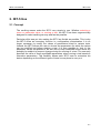
2.1 Concept
The scrolling menus make the IBT-5 very simple to use. Whether selecting a
menu or parameter value, or running a test, the IBT-5 has been ergonomically
designed to make handling as easy and fast as possible.
Particular effort was put into making the IBT-5 as flexible as possible. This is why
the IBT-5 offers an innovatory function i.e. configuration customization. It is no
longer necessary to modify the values of parameters linked to various tests.
Instead, the IBT-5 allows the user to choose the parameters for which the values
can be modified just before starting a test. It is then possible to 'lock in' the
parameter values considered to be 'set' and to keep modifiable those which will
probably be subject to frequent change during the running of a test. The user only
specifies the value of these modifiable parameters when running a test based on
interactive parameters. This flexibility allows each IBT-5 user to customize his
device depending on the different types of tests he may have to carry out.
2-1
IBT-5 Use
IBT-5 User Manual
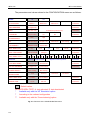
The parameters and values related to the CONFIGURATION menu are as follows:
TE
NT
EDSS-1**
BTNR191**
MODE*
L3 PROTOCOL
OWN ADDRESS
27 digits max
SPID**
30 char. max
B CHANNEL
Bx (B1 or B2)
B1
100 Ω
High
TEI
PMP (TEI Dyn)
PP (TEI = 0)
X.25 PARAM***
Standard Profile
User Profile
S0 IMPEDANCE
1 min
BERT DURATION
SERV TEST MODE
SUPP SERV TEST***
Interactive
for American protocols only
Interactive
B2
Interactive
No Protocol
15 min
1h
Auto-Config.
24 h
Interactive
Infinite
Interactive
Charged
CLIP
CLIR
COLP COLR
A
A
A
D
...
Interactive
Free of Charge
D
Swissnet 2**
D
A
D
Interactive
SUB
A
D
D
TP
A
D
HOLD
CFU
CFB
CFNR
CUG
A
A
A
A
A
D
D
D
Speech
LOOP BOX MODE
All Incom Call
WG Remote
Interactive
CALLED ADDRESS
27 digits max
or phone book
Interactive
Net. Priority
Batt. Priority
Full
All Errors
Available
Not Available
Interactive
A Law
Mu Law
Interactive
SOUND SIGNS
USER-USER SIGN
CODING LAW
depends on the L3 protocol
D
SERVICE
POWER SUPPLY
Audio 3.1 kHz
AOC
A
Test Errors
No Sound
Default values
For SUPP SERV TEST: A: test activated, D: test deactivated
*
Available only with the 'NT Simulation' option
**
According to the ordered configuration
***
Available only with the 'Commissioning' option
Fig. 2-1: Structure of the CONFIGURATION menu
2-2
Interactive
D
IBT-5 User Manual
IBT-5 Use
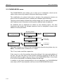
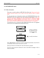
2.2 CONFIGURATION menu
This menu contains the installation parameters and the customization menu
parameters. It enables the user:
• To select a current value in a scrolling menu or to define a value according to
parameter type. This value will be automatically taken into account in all
corresponding menus or measurements.
• To indicate the interactive value: no intrinsic value is allocated to the
parameter. The instrument automatically asks for the value when it is needed
for a given measurement.
The modification of a parameter is stored in the permanent memory as soon as it
is validated by the Yes key. When the configuration is modified, the Clr key is
used to return to the previous value of the configuration parameter. Activate the
key a second time to return to the MAIN MENU.
When the user switches the instrument off, the value which has been changed in
the configuration retains its new value. The configuration can be returned to its
initial setup at any time (default values for all the parameters) using the RESET
function.
2.2.1 Instrument configuration parameters
The modification of an instrument configuration parameter is taken into account as
soon as it has been validated by the Yes key.
2.2.1.1 TE / NT operating mode ('NT Simulation' option only)
When the IBT-5 is equipped with the 'NT Simulation' option, it has two operating
modes - TE (Terminal simulation) and NT (ISDN Network simulation for protocols
EDSS-1, 1TR6, 1TR67, Swissnet3, VN3, VN4 and TPH 1962). The terminal
simulation tests are run at interfaces S0 and U in TE mode. If the NT mode is
selected, the user runs the tests for the IBT-5 connected to the S0 interface of an
ISDN device by simulating the network (when operating in NT mode, the IBT-5
must be equipped with the accu-pack and NT S2500 adapter).
2-3
IBT-5 Use
IBT-5 User Manual
2.2.1.2 Power supply priority
Two operating modes are available on the IBT-5: through the network or from the
rechargeable batteries. If both of them are available, the priority has to be defined.
The SUPPLY parameter can be positioned on 'Net. priority' or 'Batt. priority'.
In the particular case of this parameter, the value is taken into account when
connecting the IBT-5.
2.2.1.3 Sound signs (buzzer)
The SOUND SIGNS configuration parameter is used to select the events to be
indicated by the buzzer:
• No signal: 'No Sound',
• Test errors: 'Test errors',
• Key and test errors: 'All errors',
• All events: 'Full'.
2.2.1.4 S0 interface impedance
The terminal resistance is selected by the S0 IMPEDANCE configuration
parameter which can be positioned on '100 Ω' or on 'High' (i.e. high impedance).
2.2.2 Protocol configuration parameters
All modifications of the protocol configuration parameters are taken into
consideration as soon as they are validated by the Yes key. It is always possible
to configure a parameter in 'Interactive' mode in order to select a value when the
test is run. For incoming calls, if a parameter is in the 'Interactive' mode, it is the
default value which is taken into account.
2.2.2.1 Voice coding law
The IBT-5 provides for two coding laws. The CODING LAW parameter can be
positioned on 'A Law' or 'Mu Law'.
2-4
IBT-5 User Manual
IBT-5 Use
2.2.2.2 TEI management
The IBT-5 can be connected to three types of interface. The TEI parameter is
used to select 'PMP (Dyn TEI)', 'PP (TEI = 0)' and 'No Protocol' in the case of a
permanent link. The 'Auto Config.' value in the TEI parameter indicates that the
IBT-5 is automatically attempting to configure this parameter when the device is
powered up. If the network does not allow for TEI autoconfiguration, the default
value is used. The user can interrupt the autoconfiguration by pressing the Clr
key.
2.2.2.3 Layer 3 protocol
The IBT-5 handles as standard up to four different layer 3 protocols which can be
configured by means of the L3 PROTOCOL parameter (this does not apply to IBT5's equipped with only one protocol). The interactive value is allowed if at least two
protocols are available. The values of the layer 3 protocol are as follows:
EDSS-1, 1TR6, VN3, VN4, Swissnet 2 and 3, BTNR191, TPH1962, NTT, Q.931,
Telenokia, Televerket, QSIG, V1, 1TR67, AT&T Custom, N-ISDN, DMS-100
functional, TN1R6 and Cornet-T® (registered trademark of Siemens AG).
For users wishing a selection of protocols other than the protocols supplied by
default, please read paragraph 2.8 'INFORMATION menu'.
2.2.2.4 Service profile identifier (SPID) (American protocols only)
The SPID (Service Profile IDentifier) is widely used in Australia and in the United
States, but not in Europe. The SPID parameter is only used by the following
protocols: N-ISDN, AT&T Custom and DMS-100. The SPID is a parameter which
is sent by a user (terminal) to the network. This allows the network to assign two
identifiers known as the USID (User Service IDentifier) and TID (Terminal
IDentifier) to the transmitting terminal. The value can be entered in the SPID
parameter.
2.2.2.5 Address of the installation
If required, the terminal address can be entered in the OWN ADDRESS
parameter. The format is : address*subaddress.
For the 1TR6, TN1R6 and Swissnet 2 protocols, the extension value (EAZ) must
be entered in the sub-address part of the own address. Only the first figure in the
sub-address is taken into account. Its default value is '0'. Global calls are
accepted.
2-5
IBT-5 Use
IBT-5 User Manual
2.2.2.6 User to user signalling availability
This parameter reflects the availability of the User to User Signalling (UUS)
system to which the IBT-5 is connected. When the USER-USER SIGN
configuration parameter indicates that the device is 'available', it always adds a
specific UUS when establishing a call for a BERT. All Wandel & Goltermann IBT
products automatically loop back on the receiving B channel when they recognise
the specific WG UUS.
2.2.3 Test configuration parameters
A test configuration parameter is taken into account as soon as a test requiring
this parameter is run. All the test configuration parameters give the choice of the
interactive mode. In this case, the IBT-5 will prompt the user for this parameter
value each time it is needed.
2.2.3.1 B channel
The B CHANNEL parameter enables the user to select a channel using the values
'B1' or 'B2'. This precludes the use of any other channel. If preferred, the IBT-5
and network can select the channel to be used ('Bx' value).
2.2.3.2 Services
The default value of the service used for telephony and the BER test is 'Speech'.
The SERVICE parameter is used to select another service from among the ones
available for the protocol being used. The list of these services depends on the
protocol indicated in the configuration.
The same list is used during the automatic test of services and teleservices (see
paragraph 2.6 'TEST OF SERV menu').
2.2.3.3 BERT duration
The duration value for the test can be set to '1 min', '15 min', '1 h', '24 h' or
'infinite'. All five values can be configured using the BERT DURATION parameter.
2-6
IBT-5 User Manual
IBT-5 Use
2.2.3.4 Automatic test of services mode
In the 'Free of Charge' mode, the test result is supplied only after receiving the
SETUP ACK. This means that no charge will be made for the test. In the
'Charged' mode, the test result is returned after receipt of CONNECT or ALERT.
In this case, the test is charged. Both these values are accessible through the
SERV TEST MODE parameter.
2.2.3.5 Supplementary services test for EDSS-1, SN3 and 1TR67 (option)
The CONFIGURATION menu is used to validate or invalidate the supplementary
services which will be tested automatically from the 'Supp Serv' sub-menu. For
each of the following supplementary services, the user can choose whether or not
to test its availability on the network.
CLIP
Identification of calling party number on called party receiver
CLIR
Possibility for the calling party not to reveal his number to the called party
COLP
Identification of the connected number on the calling party receiver
COLR
Possibility for the called party not to reveal his number to the calling party
SUB
Called party sub-address
AOC
Advice Of Charge
TP
Terminal Portability
HOLD
Hold
CFU
Call Forwarding Unconditional
CFB
Call Forwarding Busy
CFNR
Call Forwarding No Reply
CUG
Closed User Group
2.2.3.6 Loopbox mode
The LOOP BOX parameter is used to determine the conditions under which the
IBT-5 will accept an incoming ISDN call in Loop box mode. It is possible to
configure this parameter as 'All Incom Calls' (no selection) or as 'WG Remote ' for
a selection on a remote command WG in the incoming user-to-user signalling.
2-7
IBT-5 Use
IBT-5 User Manual
2.2.3.7 Called address
The address of the called party is defined as 'Interactive' by default so that it can
be entered when the tests are run. This address can be configured in advance in
the CALLED ADDRESS parameter (27 digits maximum).
When entering the address and sub-address, the format is: address*subaddress.
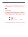
2.2.3.8 X.25 parameters (option)
The IBT-5 manages X.25 parameter profiles. There is a standard profile by default
with a parameter value that can be modified by the user. When the value of at
least one of these parameters is modified by the user, the parameter used and
displayed becomes a 'User' type parameter. The profile configuration is stored in
the memory and presented for all X.25/D tests as long as the user does not
choose to return to the 'Standard' profile.
X 25 PARAM
(Standard)
X 25/D Profile
(Standard)
read or modify
values
select another profile
The value of the parameters associated with a profile can be fixed or configured in
the 'Interactive' mode so that the device can request it when the test is run.
2-8
IBT-5 User Manual
IBT-5 Use
The parameters and their configurable values are as follows:
Values
X.25 parameters
P3 PROTOCOL
CCITT X25
Transpac
Standard
Profile
Austpac
PVC
or Interactive
CCITT
X.25
OWN ADDRESS
15 digits max
or Interactive
Empty
CALLED ADDRESS
15 digits max
or Interactive
Interactive
or Interactive
1
or Interactive
3
or Interactive
128
1 to 7
or Interactive
2
LCN
0 to 4095
or Interactive
2
CUG
0 to 99
or Interactive
empty
NUI
ASCII string, length: 27 char. max.
(alphanumeric characters possible)
or Interactive
empty
Hexa string, length: 32 char. max.
or Interactive
empty
ASCII string, length: 10 char. max.
(alphanumeric characters possible)
or Interactive
empty
0 to 63
TEI MODE VALUE
Auto
1 to 7
FRAME WINDOW
PACKET LENGTH
PACKET WINDOW
Facility
User Data
32
64
128
256
2.2.3.9 Exit and reset
In addition to the lines corresponding to the configuration parameters, the
CONFIGURATION menu contains two specific commands:
• 'Exit !', used to quit the CONFIGURATION menu.
• 'Reset' (or 'RESET'), used to restore all the parameters to their original
values depending on the initial configuration profile (factory-defined values).
If 'Reset' appears in lower case letters, the configuration is already in its
initial setting.
2-9
IBT-5 Use
IBT-5 User Manual
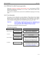
2.3 PHONE-BOOK menu
The PHONE-BOOK menu allows you to store up to 6 addresses, which can be
used in other menus by means of the phone book range number.
The modification of a phone book item is stored in the permanent memory as
soon as the two attributes (name, address) are validated by the Yes key.
The phone book display indicates the position range (n#), the name of the position
with 8 alphanumeric characters and the position address and sub-address.
An initialized item is displayed as shown by the following figure. The item
numbering (n#) recalls the escape sequence used to designate a phone book
address in a test parameter.
Scrolling fields:
MAIN MENU
PHONE-BOOK
->
<-
1# NAME
ADDRESS
2# NAME
ADDRESS
..
...
NAME
--------
1# REMOTE1
36680235
->
<-
Name ex.: REMOTE1
to modify
Add ex.:
ADDRESS
----------------
36680235
to modify
The name consists of a string of up to 8 characters entered using letters only (no
Shift). The address has a maximum of 27 digits.
The '1' key is also used like a space bar.
If the cursor is on the first position during the editing of the name and address of
an item, the user can return to the previous values by pressing the Clr key. By
pressing the Clr key again, the user returns to the MAIN MENU item. If the cursor
is not on the first position, the Clr key deletes the last digit.
In addition to the items corresponding to the six addresses, the PHONE-BOOK
menu has an EXIT item identical to the one in the CONFIGURATION menu.
2-10
IBT-5 User Manual
IBT-5 Use
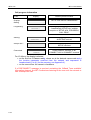
2.4 PHONE CALL menu
2.4.1 Menu description
The user is able to implement a phone call very easily directly from the PHONE
CALL menu. Before running a measurement, the user should select the value of
the parameters to be positioned in 'Interactive' mode in the CONFIGURATION
menu. The interactive parameters (CODING LAW, TEI, L3 PROTOCOL, SPID for
American protocols only, OWN ADDRESS, B CHANNEL and PHONE SERVICE)
are placed between the top of the PHONE CALL menu and the CALLED
ADDRESS parameter which is the last parameter proposed.
Configuration parameters
The parameters set to 'Interactive' in the CONFIGURATION menu are suggested
once the user enters the PHONE CALL menu.
MAIN MENU
PHONE CALL
CODING LAW
A LAW
CALLED ADDRESS
________________
Present if registered as
Interactive in the
CONFIGURATION menu
Add ex.: 36680235
to modify
36680235
CALLING ∞
36680235
ALERTING ∞
...
36680235
B1
Speech
Cld Add: 36680205
on B1 (Connected)
When 'No Protocol' is selected in the TEI management parameter, the test
connects the microphone and the earpiece to one of the two channels.
2-11
IBT-5 Use
IBT-5 User Manual
2.4.2 Address field
The syntax for address and sub-address fields (calling and called addresses) is as
follows:
Maximum number of digits
CALLED ADDRESS
(incl. sub-address): 27
0299847040*256_
The '*' is used to separate the sub-address from the address.
A decimal digit or a '#' are used to enter the PHONE CALL menu in direct mode.
In this case, the first item in the phone book is suggested (if the phone book is
initialized).
2.4.3 'Keypad' facilities
The IBT-5 enables the Keypad facilities to be tested when a call is set up. The
Keypad information element ('0' to '9', '*', '#') is encoded in place of the called
party address in the SETUP. In order to transmit the Keypad information element,
the user proceeds in exactly the same way as for a simple phone call. The Keypad
characters should be preceded by '*' in the field reserved for the called party
address.
E.g.: Call forwarding to number 7055 if line engaged (EDSS-1 protocol only):
Activation message: '*67*7055#'. The syntax is as follows:
CALLED ADDR
**67*7055#
Deactivation message: #67#. The syntax is as follows:
CALLED ADDR
*#67#
2.4.4 Overlap sending
The default dialling procedure is 'en bloc'. To activate overlap dialling (overlap
sending only) the user must validate an empty address once the address field is
displayed. The IBT-5 sends a SETUP message and runs the overlap sending
mode. The user can then dial the called address.
2-12
IBT-5 User Manual
IBT-5 Use
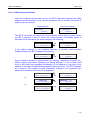
2.4.5 Use of the phone book
This procedure is available for any address parameter in all the tests.
During address editing, the phone book address is accessed by the '#' or 'n#'
escape sequence where n is a phone book item number. The first or the
designated phone book address is proposed, respectively. A phone book item is
displayed in the following form:
MAIN MENU
PHONE CALL
CALLED ADDRESS
________________
'2'
CALLED ADDRESS
2-------------
#
#
6# LOCAL
0299202020
1# REMOTE1
36680235
2# SP CLOCK
3699
0299202020
CALLING ∞
36680235
CALLING ∞
3699
...
...
CALLING ∞
...
The user can select another item by scrolling. He then validates the chosen
address by the Yes key. This action returns to the address editing screen with the
chosen address.
2.4.6 Recall procedure
In order to be available for the Recall feature, the parameters of a particular test
are retained as long as the same test is processed. The values are lost if the
CONFIGURATION or PHONE BOOK menu are used but are stored from one test
to the next.
The Recall feature without user validation of parameter values is available by
pressing the Shift and Yes keys.
2-13
IBT-5 Use
IBT-5 User Manual
2.4.7 Automatic self-call procedure
The self-call procedure is very simple: the user must set his own address and subaddress in the 'CALLED ADDRESS' field. Once the user has accepted the call, he
can run the measurement. In this case, the B channel selected by the incoming
call is set to loop back mode (Rx → Tx).
The IBT-5 displays:
xxxxxxxx
2B
Speech BC
Called address: xxxxxxxx on the two
B channels (Connected)
2.4.8 Call accept conditions
An incoming call is presented if the IBT-5 is in a MAIN MENU position and if no
other call has already been established. The following management rules are
mandatory as regards the address and sub-address:
Address management
In the following array the sub-address is ignored.
Own
address
X
Empty
X
Presented
Call
address management
X
Presented
Any or
Presented
empty
Y
Ignored
Tab. 2-1: Address management
Sub-address management
The sub-address is not taken in account in the Call accept conditions (with 1TR6
and TN1R6, the EAZ is considered).
2-14
IBT-5 User Manual
IBT-5 Use
2.4.9 DTMF (Dual Tone Multi Frequency) generation
Once the (incoming or outgoing) call has been set up, voice frequency (DTMF)
generation is obtained by pressing '0' to '9', '#' and '*' keys. Each key has its own
relative DTMF frequency.
This function is available when a phone call is established (outgoing and incoming
calls).
2.4.10 Trace information
Two types of trace information may be displayed. These fields will not display
protocol frames or messages; they indicate only the interpretation of the traces.
The first trace usually concerns the processing of the call. The second type of
trace information corresponds to the call status (setup successful or not).
Important:
The IBT-5 has a certain tolerance to Layer 1 interference on
the S0 interface. The screen displays an 'Interfer. on L1'
message and the LED 'S' flashes to warn the user.
These fields may display the following information:
Call status information
Trace
Layer 1 failed:
TEI error:
Layer 2 failed:
Display
Relative protocol events
L1 FAILURE !
Failure on Layer 1 establishment
(INFO 4 not received from NT)
TEI ERROR !
No TEI has been allocated
by the network
L2 FAILURE !
Failure on Layer 2 establishment
(UA not received from the network)
May be due to a wrong setup of TEI
management (PP instead of PMP)
L3 failure:
L3 ERROR: 100/3 !
INVALID INFO ELT
The message Release, Release conf
or Disconnect has been received
from the network with the Cause IE and
the 'Location' 3 parameter
2-15
IBT-5 Use
IBT-5 User Manual
Call progress information
Trace
Display
Relative protocol events
Overlap
dialling
NUM:
Progressing:
xxxxxxxx
CALLING ∞
Outgoing call in progress (Layer
2 established) SETUP sent, possible
reception of SETUP ACK, PROGRESS,
CALL PROC.
Alerting:
xxxxxxxx
ALERTING ∞
Outgoing call
ALERTING received
Accept call ?:
Connected:
ACCEPT CALL ?
xxxxxxxx
B1
SPEECH
SETUP sent without called address
Incoming Call
SETUP received
Called Address: xxxxxxxx on B1
CONNECT ACK or CONNECT received
For L3 failure, the display indicates:
• on the first line: L3 error: xxx/y, where xxx is the decimal cause code and y
the location parameter received from the network and expressed in
hexadecimals (0 to A) (for the meaning, see Appendix 4).
• on the second line: the cause in characters.
If a DISCONNECT message is received containing the 'InBand Tone available'
information element, the IBT-5 authorises listening to the tone until the network or
user interrupts the call.
2-16
IBT-5 User Manual
IBT-5 Use
2.4.11 Addressing information
Once the outgoing call has been set up, the IBT-5 alternately displays the called
address and the address of the remote equipment that is actually connected (if
supplied by the network).
Called address
36680235
B2
SPEECH
Connected address
>
B2
36680835
SPEECH
The IBT-5 can detect the reason for the non-display of the calling number. When
the IBT-5 receives a call for which the calling number non-display option is
activated (CLIR activated), the screen displays the following:
CLIR ON
CALL ACCEPTED ?
B2
CLIR ON
SPEECH
If the calling address is not available because of network interconnection
(Digital/Analog), the IBT-5 displays the following:
DGT/ANLG NETWORK
CALL ACCEPTED ?
DGT/ANLG NETWORK
B2
SPEECH
Some accesses subject to authorisation (fire brigade, emergency services etc.)
always supply information regarding the calling address i.e. the number itself
(even if the caller has requested non-display of his address or only part of the
address in the case of Digital/Analog network interconnection). The IBT-5 displays
all or some of the number and the information relating to the requested nondisplay of the address (the letter 'R' is displayed).
36680235
CALL ACCEPTED ?
36680235
B2
SPEECH
CLIR ON
CALL ACCEPTED?
36680235
R
B2
SPEECH
DGT/ANLG NETWORK
CALL ACCEPTED?
01033 INW
B2
SPEECH
or
or
2-17
IBT-5 Use
IBT-5 User Manual
2.4.12 Advice of charge
During and at the end of calls, charging information may be viewed for the
following protocols: EDSS-1, VN3, VN4, Swissnet 3, 1TR6, TN1R6 and 1TR67.
Depending on the features of the network to which the IBT-5 is connected, the
information is given either in units or in currency and displayed alternately with the
called address.
Ex.
xxxxxxxx
B1
SPEECH
<->
UNITS
B1
3
SPEECH
or
5 50 DM
B1
SPEECH
When charging information is received at the end of the call, the IBT-5 displays a
specific screen indicating the total cost of the call.
Note:
2-18
This function is available only in PHONE CALL mode.
IBT-5 User Manual
IBT-5 Use
2.5 BIT ERR RATE menu
2.5.1 Menu description
This menu is used to perform a BER (Bit Error Rate) test. Errors can then be
inserted manually during a test in order to test the network's ability to support
them.
For the parameter set in 'Interactive' mode in the CONFIGURATION menu, the
parameter(s) must be chosen by the user before the measurement is run. The
interactive parameters (CODING LAW, TEI, L3 PROTOCOL, SPID for American
protocols only, OWN ADDRESS, USER-USER SIGN, B CHANNEL, BERT
BEARERCAP and BERT DURATION) are offered between the top of the BERT
menu and the CALLED ADDRESS parameter which is the last one suggested.
The parameters set to 'Interactive' in the CONFIGURATION menu are suggested
once the user has validated the BIT ERR RATE menu.
MAIN MENU
BERT
CODING LAW
A LAW
CALLED ADDRESS
--------------
Present if registered
as 'Interactive' in the
CONFIGURATION
menu
to modify the address
xxxxxxxx
CALLING ∞
...
When 'No Protocol' is selected in the TEI management parameter, the self-call is
not available and the remote command is not sent.
When the channel is not fixed by the user (Bx value) B1 is chosen.
The WG remote loop back command is sent in the SETUP message if UUS is
declared available.
2-19
IBT-5 Use
IBT-5 User Manual
For the call procedure structure, see the description in the 'Trace' paragraph of the
PHONE CALL menu. If the connection is successful, the test is run automatically.
After the end of the first test, the connection is maintained during the reading of
the results in order to be able to propose the same test again.
It is also possible to use the recall, self-call and phone book functions as
described in the PHONE CALL menu.
The BER data is described below:
Display
Menu steps and meaning
B1 WAITING PRBS
Error rate too high
The loop is not connected
B1
BER Information 1
Synchronization
SYNCHRO
0299847040
B1
BERT
BER Information 2
Synchronization done, BER test running, no error occurs
0299847040
1 Error Sent
BER Information 3
Manual insertion of a bit error
B1
ERROR
1:00
ES=xx (or SES=xx)
0299847040
B1
BERT
BER Information 4
BER test finished and no error is found
B1
BER Information 5
BER test finished and an error is found
BERT ERROR !
< error type>
Error type or item
EFS
ES
SES
US
BEC
BER
BERT once again ?
Important:
2-20
BER Information 3
Synchronization done, BER test running, error occurs
Meaning
Error Free Second (%)
Errored Second (%)
Severely Errored Second (%)
Unavailable Second (%)
Bit Error Count
Bit Error Rate
Propose to run the test once again
BER information 3 has priority over BER information 2.
BER information 3 consists of a real-time error counter.
IBT-5 User Manual
IBT-5 Use
The IBT-5 has a certain tolerance to Layer 1 interference on
the S0 interface. The screen displays an 'Interfer. on L1'
message and the LED 'S' flashes to warn the user.
2.5.2 Manual error insertion
The IBT-5 enables the user to insert errors manually during a BERT by pressing
the '0' key. The bit error is then displayed on the monitor.
2-21
IBT-5 Use
IBT-5 User Manual
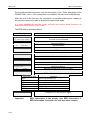
2.6 TEST OF SERV menu (Test of services)
2.6.1 Menu description
In this menu, the IBT-5 can carry out three types of test:
• Test of Bearer Capability / teleservices HLC & LLC (standard version),
• X.25/D Channel test (instrument equipped with the 'Commissioning' option),
• Supplementary services test for EDSS-1, SN3 and TR67 (instrument
equipped with the 'Commissioning' option).
'Commissioning'
option
X 25/D Test
.
.
CALLED ADDR
-------------Run Test
'Commissioning'
option
MAIN MENU
TEST OF SERV
Supp Serv
BC/Telesrv
.
.
CALLED ADDR
--------------
:
.
.
CALLED ADDR
--------------
Run Test
Run Test
2.6.1.1 Test of Bearer Capability (BC) / teleservices (HLC & LLC)
The device can implement an automatic test of services and teleservices. In this
menu, the bearer capability modes are tested, with the teleservices if necessary.
Before running a BC/Telesrv. test, the user selects the value of the parameter(s)
positioned in 'Interactive' mode in the CONFIGURATION menu. The interactive
parameters (CODING LAW, TEI, L3 PROTOCOL, SPID for American protocols
only, OWN ADDRESS, B CHANNEL and SERV TEST MODE) are proposed
between the top of the TEST OF SERV menu and the CALLED ADDRESS
parameter which is the last one proposed.
2-22
IBT-5 User Manual
IBT-5 Use
The SERV TEST MODE parameter is used to select the type of test created. In
'Free of Charge' mode, the test results are returned after receipt of SETUP ACK.
The test is not, therefore, charged. It is local and the called address does not have
to be filled in. In 'Charged' mode, the test results are supplied after receipt of the
CONNECT or ALERT messages.
It is also possible to use the recall, self-call and phone book functions as
described in the PHONE CALL menu.
This test is not available when 'No protocol' is selected for the TEI management
parameter.
For the call procedure structure, see the description in the 'Trace' paragraph of the
PHONE CALL menu. If the connection is successful, the test is run automatically.
Automatic test of services is split into two parts: a Bearer Capability test followed
by a teleservices test. At the end of the BC test, the instrument prompts the user
to test the teleservices.
The results relating to the automatic test of services and teleservices are shown
below (if the test fails, the IBT-5 displays directly the screen corresponding to the
first error detected):
Display
Serv. Test OK
EXIT !
Serv. Test NOK
EXIT !
xxxxx
Passed
xxxxx
FAIL Cause = XXX
Teleservices ?
Meaning
All the services are available. The arrows are used to
display the list of the tested services.
At least one of the services is not available. The arrows
are used to display the status of each service.
xxxxx (service/teleservice) is available on the access.
xxxxx (service/teleservice) is not available on the access.
For the meaning of the causes, see Appendix 1.
Teleservice test proposal.
2-23
IBT-5 Use
IBT-5 User Manual
2.6.1.2 X.25 in D channel test (option)
The device can run a functional test and a quality test for the X.25 in D channel
service.
Before running an X.25 in D channel test, the user selects the value of the
parameter(s) positioned in 'Interactive' mode in the CONFIGURATION menu
(X.25/D Profile). The interactive X.25 parameters (P3 PROTOCOL, OWN
ADDRESS, TEI MODE VALUE, FRAME WINDOW, PACKET LENGTH, PACKET
WINDOW, LCN, CUG, NUI, Facility and User Data) are offered between the top of
the X.25/D Test menu and the CALLED ADDRESS parameter which is the last
parameter suggested. The called address may be the IBT-5's own address (selfcall) or the address of a device capable of producing a loop.
Once the test has been run and the call set up, the IBT-5 sends a packet (the size
can be configured in advance) and compares it to the incoming packet. The test is
declared to have succeeded if the data packet is received within 3 seconds and
does not include any errors.
The results displayed after an X.25/D test are shown below (if the test fails, the
IBT-5 displays directly the screen corresponding to the error detected).
Display
X.25/D Test OK
EXIT
X.25/D Call
Clear XX YY
X.25/D Call
Diag XX
X.25/D Call
Passed
Quality Test
Passed
Quality Test
Not Possible
Test
Failed
Quality
X25/D Test NOK
EXIT
2-24
Meaning
X.25 connection set up
Incoming and outgoing packets are identical.
X.25 connection failed: CLEAR packet received
(XX, YY: hexa. values of Cause and Diag.).
X.25 connection failed: Diag. packet received
(XX: hexa. value of Diagnostic).
X.25 connection successful.
Incoming and outgoing packets are identical.
Packet could not be sent (access to an identifier)
or packet sent has not been received (e.g: absorber).
Incoming packet not identical to outgoing packet.
X.25 connection or quality test failed
IBT-5 User Manual
IBT-5 Use
2.6.1.3 Supplementary services test for EDSS-1, SN3 and 1TR67 (option)
The IBT-5 can run service availability tests concerning the following:
•
•
•
•
•
•
•
•
calling addresses (CLIP and CLIR),
connected addresses (COLP and COLR),
sub-addressing (SUB),
Advice Of Charge (AOC),
Terminal Portability (TP),
Hold (HOLD),
Call Forwarding functions (CFU, CFB, CFNR),
Closed User Group (CUG).
After validating the supplementary services to be tested in the CONFIGURATION
menu, the user runs the automatic test from the 'Supp Serv' sub-menu. If the
supplementary services test requires the inputting of a value (CFx or CUG), the
user is prompted to enter it just before the test is run.
The results displayed after a supplementary services test are shown below
(example of the CLIR supplementary service). If one or more tests fail, the IBT-5
displays directly the screen corresponding to the first error detected.
Screen
CLIR
Available
CLIR
Unavailable
Meaning
Supplementary service available
Supplementary service not available
CLIR
FAIL Cause = XX
The test could not be run. The test requires a self-call
(XX: hexadecimal value of cause)
CLIR
Inconclusive
The test provides no conclusions of service availability
In the case of the AOC test, the IBT-5 supplies the user with the type of charge
information supplied by the network (Setup, During or End): AOC-S, D, E or the
combination supported (SD, DE etc.).
2-25
IBT-5 Use
IBT-5 User Manual
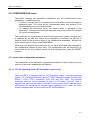
2.6.1.4 Interrogation, activation and deactivation of call forwardings for EDSS-1,
SN3 and 1TR67 ('Commissioning' option)
The IBT-5 makes available the 'Generic Functional Protocol' in order to indicate
access configuration with regard to the status of supplementary services CFU
(Call Forwarding Unconditional), CFB (Call Forwarding when line Busy) and CFNR
(Call Forwarding when No-Response). The IBT-5 can be used to activate or
deactivate these supplementary services depending on the addresses and
services required.
To question the status of the call forwarding configuration, select the main
'SUP. SERVICES' menu, validate 'Interrogation' and select CFU, CFB or CFNR.
To activate a call forwarding, select 'Activate' in the main 'SUP. SERVICES' menu.
Having selected the required supplementary service (CFU, CFB, CFNR), select
the service (or 'All Services') and the address to which the call is to be transferred
(the address at which the forwarding is activated is the installation address
configured in the CONFIGURATION menu. If this address has not been filled in,
the forwarding will be activated for all the addresses called).
Deactivating call forwardings is performed in the same way as activation (but the
IBT-5 does not ask for an address).
MAIN MENU
SUP. SERVICES
SUP SERVICES
Deactivate
SUP SERVICES
Interrogate
SUP
SERVICES
Activate
SUP
SUP
SUP
SERVICES
CFU
SERVICES
CFU
SUP SERVICES
All Services
SUP SERVICES
IN PROGRESS ...
SERVICES
CFU
SUP SERVICES
IN PROGRESS ...
SUP SERVICES
All Services
CFx number
--------------
SUP SERVICES
IN PROGRESS ...
2-26
IBT-5 User Manual
IBT-5 Use
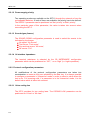
The results of the activations and deactivations may be as follows (example with
CFU):
Screen
Meaning
CFU
Activated
CFU supplementary service activated
CFU
Deactivated
CFU supplementary service deactivated
CFx error
Not available *
Supplementary service unavailable
* the message may be:
Inv.User Num: installation address error
SupServIntNotalw: unauthorised interaction
ServNotProv: basic service not provided
Ress unavailable: resources not available
Inv Div Nr: transfer address error
Special Serv Nr: special service address
DivSerUserNr: diversion to a user
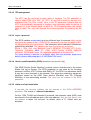
The results of an interrogation may be as follows (example with CFU):
Screen
Meaning
CFU
No Activation!
CFU supplementary service activated
<0102039999
>0102030000
Calls transferred (address 0102039999) to address
0102030000 for all services.
<
Speech
>0102030000
Calls transferred (all addresses) with
Speech service to 0102030000.
<
All Calls
>0102030000
>
< Speech.039999
>0102030000
All calls transferred (all addresses and services) to
0102030000.
Calls transferred (address 0102039999 /6 last
digits displayed) with speech service to 0102030000.
2-27
IBT-5 Use
IBT-5 User Manual
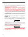
2.7 LOOP BOX menu
This menu is used to activate or deactivate the LOOP BOX mode. Two modes are
offered: ISDN LOOP BOX and X.25/D LOOP BOX.
In ISDN LOOP BOX mode, it is possible to set the loop condition for the IBT-5 to
'All Incom Calls' or 'WG Remote' in addition to the 'Interactive' mode of the
CONFIGURATION menu. If the 'Interactive' mode is stored in the
CONFIGURATION menu, both modes are offered before the test is run. The other
values offered before switching to loop mode concern TEI, L3 PROTOCOL, SPID
for American protocols only, and OWN ADDRESS if the parameters are
positioned in 'Interactive' mode in the CONFIGURATION menu. The IBT-5
automatically loops all the incoming calls as long as the user does not end the test
by pressing the Clr (or No) key.
In All Incom Calls mode, the B channel selected by the incoming call is set to
loop-back mode (Rx → Tx).
In WG Remote mode, the incoming call is accepted if the UUS contains the WG
remote loop back command. The B channel selected by the incoming call is set to
loop-back (Rx → Tx).
When 'No protocol' is selected in the TEI management parameter, the selected B
channel is set in loop-back mode (Rx → Tx). When the user does not enter the
channel (Bx value), B1 is selected.
In ISDN LOOP BOX mode, the IBT-5 displays the following:
2826
B1
Speech
In X.25/D LOOP BOX mode, the IBT-5 offers the user the parameters configured
in interactive mode in the X.25/D profile of the CONFIGURATION menu before it
is activated. The IBT-5 then loops back on all incoming calls automatically as long
as the user does not end the test by pressing the Clr (or No) key.
In X.25/D LOOP BOX mode, the IBT-5 displays the following:
2826
Con. LCN: xx
when XX is the logical channel number
In order for the IBT-5 to automatically restart in LOOP BOX mode (ISDN or
X.25/D) after a deconnection/reconnection, none of the parameters should
be in 'Interactive' mode.
2-28
IBT-5 User Manual
IBT-5 Use
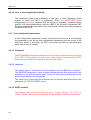
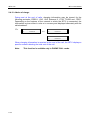
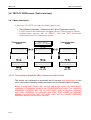
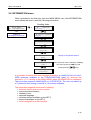
2.8 INFORMATION menu
When activated by the Yes key from the MAIN MENU item, the INFORMATION
menu allows the user to read the following information.
Scrolling fields:
MAIN MENU
INFORMATION
->
VERSION
V03.01B
'1 2 3'
Change of
language and protocols
SERIAL NUMBER
CE0200
HARDW LEVEL
1
LANGUAGE
English
SOFTW OPTION
None
Display of configurable options
L3 PROTOCOL
1TR6
Other protocols can be viewed by validating
this menu (press the YES key) and
scrolling with the
keys.
CONFIG
Standard
It is possible to switch from one language to another or modify the list of Level 3
ISDN protocols available in the CONFIGURATION menu by entering the
sequence '1 2 3' directly in the MAIN MENU when INFORMATION is displayed.
The menu then proposes LANGUAGE or L3 PROTOCOL. The user can select up
to 7 protocols from among a total list of 19 currently available.
The information supplied concerns the following:
• software version and revision number,
• instrument serial number,
• hardware level,
• selected language,
• software options available on the IBT-5,
• protocols available on the IBT-5,
• initial configuration profile identifier.
2-29
IBT-5 Use
IBT-5 User Manual
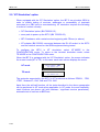
2.9 'NT Simulation' option
When equipped with the 'NT Simulation' option, the IBT-5 can simulate ISDN in
order to enable testing of services, addresses or accessibility of terminals
connected to a PBX prior to commissioning. NT simulation requires the following
in order to function correctly:
• 'NT Simulation' option (BN 7522/92.15),
• accu-pack to power up the IBT-5 (BN 7522/90.22),
• IBT-5 hardware, with a serial number beginning with CExxxx (or above),
• NT adapter (BN S2500) connected between the RJ-45 socket in the IBT-5
and the network access on the ISDN equipment being tested.
To configure the IBT-5 in NT simulation, select NT MODE in the
CONFIGURATION menu. To return to the terminal simulation mode, select
TE MODE in the CONFIGURATION menu.
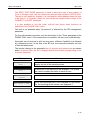
When the IBT-5 is equipped with the 'NT Simulation' option, the screen indicates
the current mode (NT or TE). In this case, each main screen displays the mode:
NT mode
MAIN MENU NT
TEST OF
TE mode
MAIN MENU TE
TEST OF
The protocols supported by the IBT-5 in NT mode are as follows: EDSS-1, 1TR6,
1TR67, Swissnet 3, VN3, VN4 and TPH 1962.
Apart from the self-call function, all the tests described in the above paragraphs
can be performed in NT mode when applicable. In NT mode, the most frequentlyused functions are phone call (with address / significant service parameters),
automatic test of services or BER test.
2-30
IBT-5 User Manual
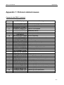
Appendices
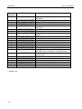
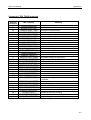
Appendix 1: Protocol-related causes
Causes for the EDSS-1 protocol
Decimal
Cause/val
1
2
3
6
7
16
17
18
19
21
22
26
27
28
29
30
31
34
38
41
42
43
44
47
49
50
57
58
63
65
66
69
IBT-5 Display
Meaning
Unallocated (unassigned) number
No route to specified transit network
No route to destination
Channel unnacceptable
Call awarded and being delivered in an
established channel
Normal call clearing
(nothing displayed)
User busy
USER BUSY
NO USER RESPONDG No user responding
NO ANSWER < USER No answer from user (user alerted)
Call rejected
CALL REJECTED
NUMBER CHANGED Number changed
NON SEL USER CLR Non-selected user clearing
DEST OUT OF ORDER Destination out of order
INVALID NUM FORM Invalid number format
Facility rejected
FACILITY REJECT
RESP TO STAT ENQ Response to STATUS ENQUIRY
NORMAL:UNSPECIF. Normal, unspecified
NO CHANNEL AVAIL No circuit/channel available
NET OUT OF ORDER Network out of order
TEMPORARY FAILUR Temporary failure
NETWORK CONGEST Switching equipment congestion
ACCESS INFO DISC Access information discarded
REQ CHAN UNAVAIL Requested circuit/channel not available
RESOURCE UNAVAIL Ressources unavailable, unspecified
QOS UNAVAILABLE Quality Of Service unavailable
REQ FAC NOT SUBS Requested facility not subscribed
BEAR CAP UNAUTH Bearer capability not authorized
UNAVAIL BEAR CAP Bearer capability not presently available
Service or option not available, unspecified
UNAVAIL SERVICE
N-IMPLE BEAR CAP Bearer capability not implemented
N-IMPLE CHAN TYP Channel type not implemented
Requested facility not implemented
N-IMPLE FACILITY
UNALLOCATED NUMB
NO ROUTE TO NETW
NO ROUTE TO DEST
CHANNEL UNACCEPT
CALL AWARDED
A-1
Appendices
IBT-5 User Manual
Decimal
Cause/val
70
IBT-5 Display
Meaning
ONLY RESTR.BEAR
79
81
82
83
N-IMPLE SERV/OPT
INVALID CALL REF
N-EXIST CHANNEL
N-EXIST CALL ID
84
85
86
CALL ID IN USE
NO CALL SUSPENDD
CALL ALR CLEARED
87
88
90 *
91
95
96
97
98
USR NOT MEMB CUG
INCOMPATIB.DEST
DEST.ADDR.MISS
INVA TRANSIT NET
INVALID MESSAGE
MANDAT INFO MISS
N-EXIST MSG TYPE
N-IMPL MSG TYPE
99
N-EXIST INFO ELT
100
101
102
111
127
Others
INVALID INFO ELT
INCOMPATIBLE MSG
RECOVERY ON TIMR
PROTOCOL ERROR
INTERWORKING
Unknown Cause
Only restricted digital information bearer capability
is available
Service or option not implemented, unspecified
Invalid call reference value
Identified channel does not exist
A suspended call exists, but this call identity does
not exists
Call identity in use
No call suspended
Call having the requested call identity has been
cleared
User not member of Closed User Group
Incompatible destination
Destination address missing
Invalid transit network selection
Invalid message, unspecified
Mandatory information element is missing
Message type non-existent or not implemented
Message not implemented with call state or
message type non-existent or not implemented
Information element non-existent or not
implemented
Invalide information element contents
Message not compatible with call state
Recovery on timer expiry
Protocol error, unspecified
Interworking, unspecified
* BTNR191 only
A-2
IBT-5 User Manual
Appendices
Causes for 1TR6, TN1R6 protocols
Decimal
Cause/val
00
01
02
03
04
05
06
07
08
09
10
11
12
15
16
17
18
20
21
22
23
24
28
29
30
31
IBT-5 Display
(nothing displayed)
INVALID CALL REF
N-IMPLE MSG TYPE
N-IMPLE BEAR CAP
N-IMPL CONN TYPE
N-IMPLE CHAN TYP
N-EXIST CHANNEL
N-EXIST CALL ID
CALL ID IN USE
OVERLAP UNAUTH
NO CHANNEL AVAIL
(nothing displayed)
CIRC OPERATIONAL
(nothing displayed)
N-IMPLE FACILITY
REQ FAC NOT SUBS
NORMAL:UNSPECIF.
INVA TRANSIT NET
UNAVAIL SERVICE
DEST OUT OF ORDR
DEGRADED SERVICE
NET OUT OF ORDER
NETWORK CONGEST
UUS DISCARDED
RESOURCE UNAVAIL
ONLY RESTR. BEAR
32
33
34
35
37
38
39
40
OUTG CALL BARRED
USER ACCESS BUSY
NEGATIV CUG EXPR
NON EXISTENT CUG
N-IMPLE SERV/OPT
INVALID DIGIT
MANDAT INFO MISS
N-EXIST MSG TYPE
Meaning
Invalid call reference value
Message not implemented
Bearer service not implemented
Connection type not implemented
Channel type not implemented
Identified channel does not exist
Call identity does not exist
Call identity in use
Overlap sending not allowed
No channel available
Normal call clearing
Operational circuit
Normal call clearing
Requested facility not implemented
Requested facility not subscribed
Normal unspecified
Invalid transit network selection
Unavailable service
Out of order (user)
Degraded service
Network out of order
Network congestion
User info discarded
Network resource not available
Only restricted digital information bearer capability
is available
Outgoing call barred
User access busy
Negative CUG comparison
Non-existent closed user group
Service not implemented
Invalid digit (Overlap sending)
Mandatory Info element missing
Invalid message
A-3
Appendices
Decimal
Cause/val
41
42
43
45
46
47
48
49
50
51
52
53
54
56
57
58
59
61
62
64
88
89
90
96
100
112
113
114
115
127
Others
A-4
IBT-5 User Manual
IBT-5 Display
Meaning
Message not compatible with call state
Non-existent information element
Invalid information element contents
Protocol error
Internetworking
Invalid number format
Not used
Not used
Not used
Incompatible destination
Non-existent abbreviated address entry
Destination not obtainable
Destination address missing and direct call not
subscribed
NUMBER CHANGED Number changed
DEST OUT OF ORDR Out of order
NO USER RESPONDG No user responding
User busy
USER BUSY
INCO CALL BARRED Incoming calls barred
Call rejected
CALL REJECTED
DEGRADED SERVICE Degraded service
INCOMPATIB. DEST Incompatible destination
NETWORK CONGEST Network congestion
Remote user initiated
R-USER INITIATED
MANDAT INFO MISS Mandatory information element missing
Invalid information element contents
INVALID INFO ELT
LOCAL PROC ERROR Local procedure error
REMOTE PROC ERR Remote procedure error
REMOTE USER SUSP Remote user suspend
REMOTE USER RESU Remote user resume
UUS LOCALLY DISC User info discarded locally
INCOMPATIBLE MSG
N-EXIST INFO ELT
INVALID INFO ELT
PROTOCOL ERROR
INTERWORKING
INVALID NUM FORM
NO ORIG R-CHARGG
NO DEST R-CHARGG
R-CHARGG REJECT
INCOMPATIB. DEST
N-EXIST ABR ADDR
DEST N-ACCESSIBL
DEST ADD MISSING
Unknown Cause
IBT-5 User Manual
Appendices
Appendix 2: List of available services and teleservices
List of available services and teleservices (except for 1TR6, TN1R6, 1TR67 and
Swissnet 3)
Services
Speech BC
Audio 3.1 kHz
Data 64 BC
Data 56 BC
Teleservices
Speech
Data 64
Fax G3
Fax G4
Teletext
Videotext
List of available services and teleservices for 1TR6 and TN1R6
Services
Sprache (speech)
Audio 3.1 kHz
Daten (data 64)
Ton 3.1 kHz (audio)
Teleservices
Fax G3
Fax G4
Teletext
Btx
X21 Uc19
X25 Uc 13
Mixed
Fernwirken (remote)
Grafik
Bild (image)
A-5
Appendices
IBT-5 User Manual
List of available services and teleservices for 1TR67
Services
Speech BC
Audio 3.1 kHz BC
Audio 7 kHz BC
Data 64
Teleservices
Speech
X25 / B
Audio 7 kHz
Fax G3
Fax G4
BTX 64
BTX New
X21 UC19
Teletext
Bild 3.1 kHz
Bild
Data 56
List of available services and teleservices for Swissnet 3
Services
Speech BC
Audio 3.1 kHz
Data 64
Data 56 BC
Data 64 Rest BC
Audio 3.1 kHz PI
Teleservices
Speech
Audio 7 kHz
Fax G3
Fax G4
Teletext
Videotext
Videotel NFb
A-6
IBT-5 User Manual
Appendices
Appendix 3: List of X.25 causes and diagnostics
Cause 00 (DTE)
Hex
Dec
CLR command
Clear due to a X.29 invitation to CLR message
Clear due to a X.29 reselection message
Outgoing call timeout
Idle timer (VIDEOTEX)
Reception of CNX/FIN (VIDEOTEX)
Level 1 disconnected on a PAD line
$80
$81
$82
$85
$86
$87
$89
128
129
130
133
134
135
137
Cause 01 (busy - OCC)
Hex
Dec
Routing impossible: no more logical channels free
Routing impossible: call collision
Routing impossible: PAD line does not accept the call
$48
$90
72
144
Cause 03 (invalid facility request - INV)
Hex
Dec
Facility code not allowed (facility not subscribed or inexistent)
Invalid facility parameter or facility combination
Code or additional service parameter for specified DTE not
allowed by the CCITT not allowed or invalid
$41
$42
65
66
$4D
77
Cause 05 (network incident - NC)
Hex
Dec
Invalid packet type for state r1
Invalid packet type for state p1
Invalid packet type for state p2
Invalid packet type for state p3
Invalid packet type for state p4
Invalid packet type for state p6
Unknown packet type
Outgoing calls barred
Invalid logical channel (following DIAGNOSTIC packet reception)
Packet too short
Packet too long
Restart or restart confirmation on logical channel other than 0
D bit not supported
Fast select with restriction on response requested
Call timer T11 timeout
Clear timer T13 timeout
Reset timer T12 timeout
Facility code not allowed
Incorrect facility parameter or combination of parameters
Called address invalid (digit not DCB)
Calling address invalid (digit not DCB)
Facility field length incorrect
Incoming calls barred
Routing impossible: no logical channels available
Routing impossible: call collision
Repeated facility
$11
$14
$15
$16
$17
$19
$21
$22
$24
$26
$27
$29
$28
$2A
$31
$32
$33
$41
$42
$43
$44
$45
$46
$47
$48
$49
17
20
21
22
23
25
33
34
36
38
39
41
40
42
49
50
51
65
66
67
68
69
70
71
72
73
A-7
Appendices
A-8
IBT-5 User Manual
Code or facility parameter (as specified by CCITT)
of DTE not allowed
Mandatory facility not present (NUI)
RDM or DISC frame received
No response to N2 I frames
Invalid F bit received
FRMR received
Level 2 reset after reception of a FRMR frame
Level 2 reset
Telephone number busy
Telephone call collision
Telephone communication cleared
Level 2 not set up
Telephone call cancelled
Telephone call forbidden
Answering tone not detected
Telephone call delayed
T0 timeout for PSTN call
$4D
$4C
$B1
$B2
$B3
$B4
$B5
$B6
$B8
$B9
$BA
$BB
$BC
$BD
$BE
$BF
$C0
77
76
177
178
179
180
181
182
184
185
186
187
188
189
190
191
192
Cause 09 (out of order - DER)
Hex
Dec
Level 1 disconnected
Received DM or DISC frame
No response to N2 I frames
Invalid F bit
FRMR received
Level 2 reset after reception of a FRMR frame
Level 2 reset
Telephone call broken
Level 2 not set up
Telephone call cancelled
Answering tone not detected
Telephone call delayed
T0 timeout for PSTN call
LAPX disconnection
$B0
$B1
$B2
$B3
$B4
$B5
$B6
$BA
$BB
$BC
$BE
$BF
$C0
$C1
176
177
178
179
180
181
182
186
187
188
190
191
192
193
Cause 0B (access barred - NA)
Hex
Dec
Incoming calls barred
Answering tone not detected
Confidentiality not respected on outgoing line
Access to the public network not allowed
$46
$BE
$F5
$F8
70
190
245
248
Cause 0D (not obtainable - NP)
Hex
Dec
Unknown number (number not in numbering scheme)
$F0
240
Cause 11 (remote procedure error - RPE)
Hex
Dec
Invalid packet type for state r1
invalid packet type for state p2
Invalid packet type for state p3
Invalid packet type for state p4
Unknown packet type
Invalid logical
Packet too short
Packet too long
Restart or restart confirmation on logical channel other than 000
$11
$15
$16
$17
$21
$24
$26
$27
$29
17
21
22
23
33
36
38
39
41
IBT-5 User Manual
Appendices
Call confirmation invalid
Clear packet timer timeout
Reset packet timer timeout
Restart packet timer timeout
Invalid called address
Invalid calling address
Facility field length incorrect
Facility code repeated
$2A
$32
$33
$34
$43
$44
$45
$49
42
50
51
52
67
68
69
73
Cause 13 (local procedure error - ERR)
Hex
Deci
Invalid packet type for state r1
Invalid packet type for state p1
Invalid packet type for state p2
Invalid packet type for state p3
Invalid packet type for state p4
Invalid packet type for state p6
Unknown packet type
Outgoing calls barred
Packet too short
Packet too long
Restart or restart confirmation on logical channel other than 0
Call confirmation invalid
Clear packet timer timeout
Reset packet timer timeout
Restart packet timer timeout
Invalid called address
Invalid calling address
Facility field length incorrect
Facility code repeated
Facility mandatory and not present
$11
$14
$15
$16
$17
$19
$21
$22
$26
$27
$29
$2A
$32
$33
$34
$43
$44
$45
$49
$4C
17
20
21
22
23
25
33
34
38
39
41
42
50
51
52
67
68
69
73
76
Cause 19 (reverse charging acceptance not subscribed)
Hex
Dec
Reverse charging acceptance not subscribed on outgoing line
$00
0
Cause 21 (destination incompatible)
Hex
Dec
D bit not supported
Impossible to negotiate packet size
$28
$D9
40
217
Cause 29 (fast select not subscribed)
Hex
Dec
Fast-select not subscribed
$00
0
A-9
Appendices
IBT-5 User Manual
Appendix 4: Values of the 'Location' parameter for the
EDSS-1 protocol
Value (Hexa)
0
1
2
3
4
5
7
A
A-10
Meaning
User
Private network serving the local user
Public network serving the local user
Transit network
Private network serving the remote user
Public network serving the remote user
International network
Network beyond interworking point