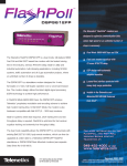
Download Telenetics DSP9612RM Network Card User Manual
Transcript
¤ DSP9612RM Flash Poll Rack-Mount Modem User’s Guide ARC Electronics 800-926-0226 www.arcelect.com 0049−0519−000 Rev. A Compliances This device complies with Part 15A of the FCC Rules. Operation is subject to the following two conditions: (1) this device may not cause harmful interference, and (2) this device must accept any interference received, including interference that may cause undesired operation. This equipment has been tested and found to comply with the limits for a Class A digital device, pursuant to Part 15A of the FCC Rules. These limits are designed to provide reasonable protection against harmful interference in a residential installation. This equipment generates, uses, and can radiate radio frequency energy and, if not installed and used in accordance with the instructions, may cause harmful interference to radio communications. However, there is no guarantee that interference will not occur in a particular installation. If this equipment does cause harmful interference to radio or television reception, which can be determined by turning the equipment off and on, the user is encouraged to try to correct the interference by one or more of the following measures: c Reorient or relocate the receiving antenna. c Increase the separation between the equipment and the receiver. c Connect the equipment to an outlet on a circuit other than the one to which the receiver is connected. c Consult the dealer or an experienced radio/TV technician for help. If none of these actions resolves the problem, consult your distributor or an experienced radio/television technician for additional suggestions. Additionally, Section 15.838, paragraph d), of the FCC Rules and Regulations states: “Where special accessories, such as shielded cables, are required in order to meet FCC regulations, shielded cables must be used with this equipment. Operation with non-approved equipment or unshielded cables is likely to result in interference to radio and TV reception. The user is cautioned that changes and modifications to this equipment without the approval of the manufacturer could void the user’s authority to operate this equipment. Contents CHAPTER 1 INTRODUCTION .........................................................5 FEATURES ................................................................................................6 APPLICATIONS .........................................................................................7 ANCILLARY DOCUMENTATION ................................................................7 CHAPTER 2 INSTALLATION ..........................................................9 UNPACKING YOUR HARDWARE ...............................................................9 ADDITIONAL ITEMS YOU NEED ...............................................................9 HARDWARE OVERVIEW .........................................................................10 Front View.........................................................................................10 Component View ...............................................................................11 INSTALLATION SUMMARY .....................................................................12 CONFIGURING THE MODEM ...................................................................12 High-Speed (Fast Poll) Mode ...........................................................12 Low-Speed (FSK) Mode ....................................................................18 INSTALLING THE MODEM IN THE UNIVERSAL DATA SHELF...................23 CONNECTING TO A TRANSMISSION LINE................................................25 Modular Jack Connectors.................................................................25 Mass Termination Connector............................................................26 CONNECTING AN RS-232 DEVICE..........................................................26 LEDS .....................................................................................................27 LOOPBACK CONTROL SWITCH ...............................................................28 APPENDIX A, TROUBLESHOOTING...........................................29 PROBLEM SOLVING ................................................................................29 APPENDIX B, SPECIFICATIONS ..................................................31 GENERAL SPECIFICATIONS ....................................................................31 MECHANICAL SPECIFICATIONS ..............................................................32 BACK-TO-BACK CONNECTIONS TO A SECOND MODEM .........................33 RS-232 (RTU) Interface ....................................................................33 ENVIRONMENTAL SPECIFICATIONS ........................................................34 COMPLIANCES........................................................................................34 APPENDIX C, LIMITED PRODUCT WARRANTY.....................35 APPENDIX D, RMA PROCEDURE ................................................36 Page iii Contents NOTES Page iv Chapter 1 Introduction C ongratulations for purchasing the finest industrial-grade fastpoll rack-mount modem available. The Telenetics DSP9612RM (Flash Poll) modem is a 9600/4800/0-1800 bps rack-mount modem designed for 4-wire, fullduplex or 2-wire, half-duplex operation over a voice-band leased line. The modem is designed utilizing the latest digital-signal processing (DSP) technology to achieve high performance. The modem employs Telenetics’ proprietary modulation and encoding scheme to achieve fast modem training time. It is also backward compatible with Bell 202 modems. The modem can be installed in either a Telenetics or a Motorola/UDS RM16M Universal Data Shelf. The modem occupies only one rack slot, eliminating the hassle of equipment trays and power bricks required for “Plastic Box” modems. The modem is powered from the Universal Data Shelf. The DSP9612RM modem is ideally suited for multi-point communication systems that require fast response time, short training time, and low throughput delay. The DSP9612RM is the most technologically advanced rack-mount modem on the market. This User’s Guide is designed to let you get your modem “up and running” as quickly as possible. It contains all the information you need to install and configure your modem. It also contains troubleshooting information in the unlikely event you encounter a problem with your modem. Page 5 Introduction Features Though functionally similar to commercial modems, the DSP9612RM provides the following unique features that make it well suited for utility and industrial applications. c Requires only one rack slot in a Telenetics or a Motorola/UDS RM16M Universal Data Shelf. c Operates over voice-band conditioned or unconditioned leased line and pilot wires. c Operates without human intervention, making it ideal for unmanned locations. c Works within an extended temperature range of -40ºC to +85ºC. c Designed with coupling transformers for high-voltage isolation and common mode noise rejection in industrial and commercial environments. c Asynchronous data rates (selectable) of 9600, 4800, and 0-1800 bps. c Easily accessible DIP switches for user configuration and option selection. c Local analog, local digital, and remote digital loopback diagnostics. Page 6 Applications Applications The DSP9612RM modem is designed for point-to-point and multipoint data communications. Figure 1-1 shows a typical multipoint configuration. Figure 1-1. Network of Multipoint Configuration There are a number of factors that can affect the network’s and modem’s operation and performance. These include: c Operating speed c 2-wire or 4-wire configuration c Transmission line characteristics, noise, and line impairments c Network configuration (point-to-point or multipoint) c Number of nodes on the network Ancillary Documentation For information about the Telenetics RM16M Universal Data Shelf, refer to the Telenetics RM16M Installation and Operation Manual for the Universal Data Shelf version you have. Page 7 Introduction NOTES Page 8 Chapter 2 Installation T his chapter describes how to install the modem. Unpacking Your Hardware Your package should include: c At least one DSP9612RM modem c This User’s Guide If your package contents are damaged or missing, please contact your place of purchase immediately. Additional Items You Need To use your modem, you need the following additional items: c A Telenetics or Motorola/UDS RM16M Universal Data Shelf c A two- or four-wire transmission line or leased line Page 9 Installation Hardware Overview Front View Figure 2-1 shows a front view of the DSP9612RM modem. Starting from the top, this view shows: c A loopback test switch. See page 28. c A set of eight LEDs. See page 27. Figure 2-1. Front View of Modem Page 10 Hardware Overview Component View Figure 2-2 shows the component view of the modem. This view shows: c Two configuration switch blocks, designated SW1 and SW2. See page 12. c Jumpers located in various positions on the modem. Do not change or remove the straps from these jumpers. c Edge connectors at the back of the modem, which plug into the backplane of a Telenetics or Motorola/UDS RM 16M Universal Data Shelf. Edge Connectors Configuration Switch Blocks Switch Block SW2 Switch Block SW1 Figure 2-2. Component View of Modem Page 11 Installation Installation Summary The modem installation involves the following steps: 1. Configuring the modem. See the section below. 2. Connecting to a transmission line. See page 25. 3. Connecting an RS-232 device. See page 26. Configuring the Modem You configure the modem using the two sets of DIP switches on the component side of the modem, near the center. The switches can have one of two functions, depending on how switch SW2-1 is set. c Setting switch SW2-1 to OFF configures the modem for highspeed (Fast Poll) mode. In this mode, the switches correspond to the functions in Table 2-1 (see page 13). c Setting switch SW2-1 to ON configures the modem for low-speed (FSK) mode. In this mode, the switches correspond to the functions in Table 2-3 (see page 18). Note: The modem has several jumpers. Do not change or remove the straps from the jumpers. High-Speed (Fast Poll) Mode Table 2-1 shows the modem switch settings that can be used when the modem is configured for high-speed (Fast Poll) mode. This mode is enabled when switch SW2-1 is set to OFF. Following this table is an explanation of these settings. Page 12 Configuring the Modem Table 2-1. Modem Switch Settings for High-Speed Mode Switches ON SW 1-1 − 1-4: Transmit Level (page 14) Switch Settings OFF (Default) (see Table 2-2 on page 14) SW 1-5: Receiver Dynamic Range (page 15) −10 to −43 dBm +3 to −30 dBm SW 1-6: TX Cable Equalizer (page 15) Enabled Disabled SW 1-7: RX Cable Equalizer (page 15) Enabled Disabled SW 1-8: Anti-streaming (page 15) Active Inactive SW 2-1: High-Speed/Low-Speed Mode (page 16) Low-Speed Mode High-Speed Mode (FSK) (Fast Poll) SW 2-2: Data Rate in Fast Poll Mode 4800 bps 9600 bps SW 2-3: Async Character 11 bits 10 bits SW 2-4: Auto RTS (page 16) Enabled Disabled SW2-5: Reserved SW 2-6: Production Test Only (page 16) Test Normal SW 2-7: 2- or 4-wire (page 16) 2-wire, halfduplex 4-wire, full-duplex SW 2-8: Carrier Control (page 17) Constant Switched SW 2-9: Rx Termination (page17) Disabled Enabled SW 2-10: Ground Options (page 17) Chassis GroundSignal Ground Connected Chassis GroundSignal Ground Disconnected Page 13 Installation SW1-1 through SW1-4 − Transmit Level (high- & low-speed modes) Switches SW1-1 through SW1-4 adjust the modem’s transmit level. Table 2-2 shows the transmit levels you can select using these switches. Table 2-2. Transmit Levels (High-Speed and Low-Speed Modes) SW1 through SW4 Switch Settings Transmit Level SW1-1 SW1-2 SW1-3 SW1-4 0 dBm OFF OFF OFF OFF −1 dBm OFF OFF OFF ON −2 dBm OFF OFF ON OFF −3 dBm OFF OFF ON ON −4 dBm OFF ON OFF OFF −5 dBm OFF ON OFF ON −6 dBm OFF ON ON OFF −7 dBm OFF ON ON ON −8 dBm ON OFF OFF OFF −9 dBm ON OFF OFF ON −10 dBm ON OFF ON OFF −11 dBm ON OFF ON ON −12 dBm ON ON OFF OFF −13 dBm ON ON OFF ON −14 dBm ON ON ON OFF +3 dBm ON ON ON ON Page 14 Configuring the Modem SW1-5 − Receiver Dynamic Range (high- & low-speed modes) SW1-5 ON = −10 to −43 dBm OFF = +3 to −30 dBm For a low receive signal level, set SW1-5 to ON (−43 dBm ). For short distances or to select a strong receive signal, set SW1-5 to OFF. SW1-6 and SW1-7 − Cable Equalizer (high-speed mode only) SW1-6 ON = Enable TX Cable Equalizer OFF = Disable TX Cable Equalizer SW1-7 ON = Enable RX Cable Equalizer OFF = Disable RX Cable Equalizer To improve or extend the modem’s polling performance, use the fixed Compromise Cable Equalizer when polling on long metallic circuits. The cable equalizer is active only when the modem is in high-speed mode (SW2-1 set to OFF). SW1-8 − Anti-streaming (high- & low-speed modes) SW1-8 ON = Anti-streaming active OFF = Anti-stream inactive Typically, anti-streaming is used in multi-point applications to prevent a malfunctioning slave modem from occupying the line indefinitely. When anti-streaming is active, the modem can transmit data for a maximum of 27 seconds before the transmitter turns off automatically. The modem then looks for an ON-to-OFF Request To Send (RTS) transition before proceeding with normal operation. Anti-streaming can be selected in either high-speed or low-speed mode. Page 15 Installation SW2-1 − Fast Poll/FSK (high- & low-speed modes) SW2-1 ON = Low-Speed Mode (FSK) OFF = High-Speed Mode (Fast Poll) SW2-1 configures the modem for either low-speed (FSK) mode or high-speed (Fast Poll) mode. As a result, the SW2-1 setting you choose determines the switch definitions for the other switches. c For high-speed mode, the configuration switches follow the definitions in Table 2-1. c For low-speed mode, the configuration switches follow the definitions in Table 2-3. SW2-4 − Auto RTS (high-speed mode only) SW2-4 ON = Enable Auto RTS OFF = Disable Auto RTS For data terminals that do not support hardware RTS, set SW2-4 to ON to enable buffer mode. In this mode, TXD is detected at the modem and internal RTS is turned ON. After training completes, the TXD is transmitted to the remote modem. The transmitter turns off if no TXD is detected after 1 character length of idle time. SW2-6 − Production Test Only (high- & low-speed modes) SW2-6 Must be OFF SW2-6 must be in the OFF position for normal operation. SW2-7 − 2-/4-Wire Operation (high- & low-speed modes) SW2-7 ON = 2-Wire, Half-Duplex Mode OFF = 4-Wire, Full-Duplex Mode SW2-7 configures the modem for 4-wire full-duplex or 2-wire halfduplex operation. Page 16 Configuring the Modem SW2-8 − Carrier Control (high- & low-speed modes) SW2-8 ON = Constant OFF = Switched SW2-8 selects either constant or switched carrier. Constant carrier allows DTEs, such as asynchronous dumb terminals or RTUs, to operate with modems, without the input RTS signal. When constant carrier mode is enabled (SW2-8 set to ON), the modem forces the transmit carrier active and the RTS-CTS delay is minimum (<0.5 ms.). You can use constant carrier in 4-wire, point-to-point or multi-point applications (from master to slave modems). In switched-carrier mode (SW2-8 set to OFF), the RTS/CTS delay is 23 ms. SW 2-9 − RX Termination (high- & low-speed modes) SW2-9 ON = Disable Rx Termination OFF = Enable Rx termination SW2-9 selects whether RX termination is enabled for a modem. If you set this switch OFF, the receiver is terminated with 600 Ω. If you set this switch ON, the receiver is not terminated. SW 2-10 − Ground Option (high- & low-speed modes) SW2-10 ON = Modem signal ground is connected to chassis ground OFF = Modem signal ground and chassis ground disconnected SW2-10 determines the grounding option for the modem. Setting this switch ON connects the modem signal ground to chassis ground. Setting this switch OFF disconnects the modem signal ground from chassis ground. Page 17 Installation Low-Speed (FSK) Mode Table 2-3 shows the modem switch settings that can be used when the modem is configured for low-speed (FSK) mode. This mode is enabled when switch SW2-1 is set to ON. Following this table is an explanation of these settings. Table 2-3. Modem Switch Settings for Low-Speed Mode Switches Switch Settings ON OFF SW 1-1 − 1-4: Transmit Level (page 19) (see Table 2-4 page 19) −10 to −43 dBm SW 1-5: Receiver Dynamic Range (page 20) SW 1-6 − SW1-7: RTS-CTS Delay (page 20) +3 to −30 dBm (see Table 2-5 page 20) SW 1-8: Anti-streaming (page 20) Active Inactive SW 2-1: High-Speed)/Low-Speed Mode (page 21) Low-Speed (FSK) Mode High-Speed (Fast Poll) Mode SW 2-2: CD Delay (page 21) 23 ms. 6 ms. SW 2-3: Turnaround SQ (page 21) 0 ms. 8 ms. SW 2-4: Not Used SW2-5: Soft Carrier (page 22) Disabled Enabled SW 2-6: Production Test Only (page 22) Test Normal SW 2-7: 2- or 4-wire (page 22) 2-wire 4-wire SW 2-8: Carrier Control (page 22) Constant Switched SW 2-9: Rx Termination (page23) Disabled Enabled SW 2-10: Ground Options (page 23) Chassis GroundSignal Ground Connected Chassis GroundSignal Ground Disconnected Page 18 Configuring the Modem SW1-1 through SW1-4 − Transmit Level (high- & low-speed modes) Switches SW1-1 through SW1-4 adjust the modem’s transmit level. Table 2-4 shows the transmit levels you can select using these switches. Table 2-4. Transmit Levels (High-Speed and Low-Speed Modes) SW1-1 through SW1-4 Switch Settings Transmit Level SW1-1 SW1-2 SW1-3 SW1-4 0 dBm OFF OFF OFF OFF −1 dBm OFF OFF OFF ON −2 dBm OFF OFF ON OFF −3 dBm OFF OFF ON ON −4 dBm OFF ON OFF OFF −5 dBm OFF ON OFF ON −6 dBm OFF ON ON OFF −7 dBm OFF ON ON ON −8 dBm ON OFF OFF OFF −9 dBm ON OFF OFF ON −10 dBm ON OFF ON OFF −11 dBm ON OFF ON ON −12 dBm ON ON OFF OFF −13 dBm ON ON OFF ON −14 dBm ON ON ON OFF +3 dBm ON ON ON ON Page 19 Installation SW1-5 − Receiver Dynamic Range (high- & low-speed modes) SW1-5 ON = −10 to −43 dBm OFF = +3 to −30 dBm For a low receive signal level, set SW1-5 to ON (−43 dBm ). For short distances or to select a strong receive signal, set SW1-5 to OFF. SW1-6 and SW1-7 − RTS-CTS Delay (low-speed mode only) Switches SW1-6 and SW1-7 determine the duration of the RTS-CTS delay. Table 2-5 shows the RTS-CTS delays you can select using these switches. Table 2-5. RTS-CTS Delays SW1-6 and SW1-7 Switch Settings RTS-CTS Delay SW1-6 SW1-7 8 ms. delay OFF OFF 33 ms. Delay OFF ON 59 ms. Delay ON OFF 219 ms. delay ON ON SW1-8 − Anti-streaming (high- & low-speed modes) SW1-8 ON = Anti-streaming active OFF = Anti-stream inactive Typically, anti-streaming is used in multi-point applications to prevent a malfunctioning slave modem from occupying the line indefinitely. When anti-streaming is active, the modem can transmit data for a maximum of 27 seconds before the transmitter turns off automatically. The modem then looks for an ON-to-OFF Request To Send (RTS) transition before proceeding with normal operation. Anti-streaming can be selected in either high-speed or low-speed mode. Page 20 Configuring the Modem SW2-1 − Fast Poll/FSK (high- & low-speed modes) SW2-1 ON = Low-Speed Mode (FSK) OFF = High-Speed Mode (Fast Poll) SW2-1 configures the modem for either low-speed (FSK) mode or high-speed (Fast Poll) mode. As a result, the SW2-1 setting you choose determines the switch definitions for the other switches. c For high-speed mode, the configuration switches follow the definitions in Table 2-1. c For low-speed mode, the configuration switches follow the definitions in Table 2-3. SW2-2 − CD Delay (low-speed mode only) SW2-2 ON = 23 milliseconds OFF = 6 milliseconds SW2-2 controls the Carrier Detect (CD) delay and is valid for lowspeed mode only. Setting this switch to ON configures the modem to turn on CD 23 milliseconds after it detects a valid carrier signal. Setting this switch to OFF configures the modem to turn on CD 6 milliseconds after it detects a valid carrier signal. SW2-3 − Turnaround Squelch Delay (low-speed mode only) SW2-3 ON = 0 milliseconds OFF = 8 milliseconds SW2-3 controls the turnaround squelch delay and is valid for low-speed mode only. Setting this switch to ON configures the modem to enable its receiver immediately after the Request To Send (RTS) signal is turned off. When this switch is set to OFF and the modem is configured for 2-wire mode (SW2-7 set to ON), the modem squelches the receiver for 8 milliseconds after RTS is turned off to prevent far-end echoes from causing data errors. Page 21 Installation SW2-5 − Soft Carrier (low-speed mode only) SW2-5 ON = Disabled OFF = Enabled SW2-5 controls the soft carrier and is valid for low-speed mode only. Setting this switch to OFF configures the modem to transmit a 900 Hz soft carrier to the remote modem after RTS is turned off. Setting this switch to ON prevents the modem from transmitting a soft carrier after RTS is turned off. SW2-6 − Production Test Only (high- & low-speed modes) SW2-6 Must be OFF SW2-6 must be in the OFF position for normal operation. SW2-7 − 2-/4-Wire Operation (high- & low-speed modes) SW2-7 ON = 2-Wire, Half-Duplex Mode OFF = 4-Wire, Full-Duplex Mode SW2-7 configures the modem for 4-wire full-duplex or 2-wire halfduplex operation. SW2-8 − Carrier Control (high- & low-speed modes) SW2-8 ON = Constant OFF = Switched SW2-8 selects either constant or switched carrier. Constant carrier allows DTEs, such as asynchronous dumb terminals or RTUs, to operate with modems, without the input RTS signal. When constant carrier mode is enabled (SW2-8 set to ON), the modem forces the transmit carrier active and the RTS-CTS delay is minimum (<0.5 ms.). You can use constant carrier in 4-wire, point-to-point or multi-point applications (from master to slave modems). Page 22 Installing the Modem in the Universal Data Shelf In switched-carrier mode (SW2-8 set to OFF), the RTS/CTS delay is 23 ms. SW 2-9 − RX Termination (high- & low-speed modes) SW2-9 ON = Disable Rx Termination OFF = Enable Rx termination SW2-9 selects whether RX termination is enabled for a modem. If you set this switch OFF, the receiver is terminated with 600 Ω. If you set this switch ON, the receiver is not terminated. SW 2-10 − Ground Option (high- & low-speed modes) SW2-10 ON = Modem signal ground is connected to chassis ground OFF = Modem signal ground and chassis ground disconnected SW2-10 determines the grounding option for the modem. Setting this switch ON connects the modem signal ground to chassis ground. Setting this switch OFF disconnects the modem signal ground from chassis ground. Installing the Modem in the Universal Data Shelf After you set the modem’s configuration switches, you can install it in a slot within a 19- or 23-inch Telenetics or Motorola RM16M Universal Data Shelf. The modem is installed or replaced from the front of the Universal Data Shelf, without disturbing the cable connections on the back of the Shelf. The modem can be installed and removed without having to remove power from the Shelf. Special tools or test equipment are not required for installing the modem. 1. Wear an antistatic wrist strap over your wrist on your bare skin (not over a shirt or jacket). 2. Remove the wrapping protecting the modem. Page 23 Installation 3. Remove the front panel of the Universal Data Shelf and pick an empty slot. 4. Hold the modem so the front panel LEDs are facing you and the edge connectors are pointing to the backplane of the Universal Data Shelf. 5. Install the modem into the selected slot in the Universal Data Shelf (see Figure 2-3). 6. Push firmly on the modem to seat it properly into the slot and backplane. The back of the Universal Data Shelf contains the connectors for interfacing to the Date Terminal Equipment and communications line. Figure 2-4 shows how the modems look when installed in the rack. 7. Replace the front panel of the Universal Data Shelf. Figure 2-3. Installing the Modem Page 24 Connecting to a Transmission Line Figure 2-4. Modems Installed in the Rack Connecting to a Transmission Line The Universal Data Shelf has different Telco options. Your version may have 16 8-pin modular jack connectors, one for each slot in the Shelf. It may also have an optional 50-pin mass-termination Telco connector. To connect your modem to a leased line using the modular jack connectors, refer to “Modular Jack Connectors,” below. To use the 50pin mass-termination connector, refer to “Mass Termination Connector” on page 26. Modular Jack Connectors The rear panel of the Universal Data Shelf has an 8-pin RJ-45 jack for each slot in the Shelf. After you install the modem into a slot, connect the slot’s corresponding RJ-45 jack to a leased line. Leased lines have four contacts: a transmit (Tx) pair and a receive (Rx) pair. For communication to occur: c The Rx line of the Shelf’s RJ-45 jack must connect to the Tx line of the other modem. Page 25 Installation c The Tx line of the Shelf’s RJ-45 jack must connect to the Rx line of the other modem. For more information, refer to the Telenetics RM16M Installation and Operation Manual for the Universal Data Shelf version you have. Mass Termination Connector As an option, a 50-pin mass-termination connector can be used as the Telco connection for the modem(s). For more information, refer to the Telenetics RM16M Installation and Operation Manual for the Universal Data Shelf version you have. Connecting an RS-232 Device The Universal Data Shelf has different RS-232 options for accepting an attached RS-232 (RTU) device. Your version may have a female, 25pin RS-232 connector for each slot in the Shelf. It may also have an optional 50-pin mass-termination Telco connector. For more information, refer to the Telenetics RM16M Installation and Operation Manual for the Universal Data Shelf version you have. Page 26 LEDs LEDs The front panel of the modem provides the LEDs shown in Table 2-7. Table 2-7. Modem LEDs LED Color Description Power Green Power RTS Yellow Request To Send CTS Yellow Clear To Send TxD Yellow Transmit Data RxD Yellow Receive Data DCD Yellow Carrier Detect ALB Red* Analog Loopback DLB Red* Digital Loopback * When the modem is in remote loopback, both the ALB and DLB LEDs go ON. Page 27 Installation Loopback Control Switch The front panel of the modem has a push button for initiating the following loopback diagnostic tests: c Local analog loopback started by pressing the button one time. c Local digital loopback started by pressing the button two times. c Remote digital loopback set the local modem’s RTS signal to low. Then press the remote modem’s diagnostics button three times and raise the local modem’s RTS signal to start the test. The ALB and DLB LEDs go ON when the modem is in remote digital loopback. This test is only available in Fast Poll mode only. Figure 2-6 illustrates these three diagnostics. Figure 2-6. Loopback Diagnostics Page 28 Appendix A Troubleshooting I n the event you encounter a problem using your Telenetics modem, refer to the troubleshooting information in this appendix. To troubleshoot the power supply and backplane on the Universal Data Shelf, refer to the Telenetics RM16M Installation and Operation Manual for the Universal Data Shelf version you have. , IMPORTANT If you encounter a problem with your modem, be sure the modem switches are set to the appropriate positions. If a switch is halfway between an on and off setting, the modem will not operate properly. Problem Solving Table A-1 offers troubleshooting solutions for modem problems. Table A-1. Troubleshooting Suggestions If… Perform These Procedures… Modem does not respond and all LEDs are off. Check the Universal Data Shelf’s power supply module(s). Modem does not receive data, and the DCD and RxD LEDs are off. The receive line pair may be disconnected from the modem. Make sure the transmission line connection to the rear panel of the Universal Data Shelf is accurate and secure. The receive signal level may be below the CD threshold. Set SW1-5 ON to see whether configuring the modem for a −43 dBm threshold resolves the problem. Page 29 Troubleshooting Table A-1. Troubleshooting Suggestions If… Perform These Procedures… The RTS, CTS, and TxD LEDs do not blink. The attached terminal or DTE may not be sending data to the modem. Verify that data is being transmitted. If data is being transmitted, make sure the RS232 cable is sound and securely connected to the modem and terminal or DTE. Page 30 Appendix B Specifications General Specifications Data rate: 9600, 4800, or 0-1800 bps asynchronous Data format: 8 or 9 data bits with 1 or more stop bits DTE interface: EIA RS-232 or V.24 compatible Line conditions: TELCO Voice band 4- or 2-wire leased line, conditioned or unconditioned Private metallic circuits up to 9.5 miles (24 AWG) without cable equalizer. Up to 15.0 miles (24 AWG) with TX and RX cable equalizer Operating modes: 2-wire half-duplex or 4-wire full-duplex Modulation: High-speed fast poll – Telenetics proprietary FSK, Bell 202T compatible • Mark = 1200 Hz • Space = 2200 Hz • Soft Carrier = 900 Hz Equalizer: Automatic, adaptive RTS-CTS Delay: 23 ms. (fast poll) 8, 33, 59, or 219 ms (FSK) Page 31 Specifications Receiver dynamic range: 0 to –30 dBm or –10 to –43 dBm Operating temperature: -40°C to +85°C Surge protection: Leased line, up to 15KV Carrier Control: Constant or switched, DIP switch selectable Carrier loss recovery: Train on Data Throughput delay: Less than 10 milliseconds for fast polling. Auto RTS: Support DTE without hardware RTS (high speed only) Anti-Streaming: 27-second timer to prevent transmitter lock-up network Mechanical Specifications Dimensions: 9 inches deep x 6.25 inches high x .87 inches thick Weight: 8 ounces (card only) Page 32 Back-to-Back Connections to a Second Modem Back-to-Back Connections to a Second Modem Rx Rx Rx Rx Tx Tx Tx Tx Modem 1 Modem 2 RS-232 (RTU) Interface Signal Name Modem Input/Output DB25 Pin Description Earth GND 1 Earth Ground TXD Input 2 Transmit Data RXD Output 3 Receive Data RTS Input 4 Request To Send CTS Output 5 Clear To Send DSR Output 6 Data Set Ready (Modem Ready) SG - 7 Signal Ground DCD Output 8 Data Carrier Detected DTR Input 20 Data Terminal Ready (Host Ready) Page 33 Specifications Environmental Specifications Operating temperature: -40 to + 85o C Storage temperature: -40 to +125o C Operating humidity: 5 to 95 %, non-condensing. Isolation: 3750 V RMS Surge protection: Leased line up to 15K VA Compliances The modem is designed to meet the following agency requirements: EMI/RFI: FCC part 15 for Class A computing device Industry Canada. (Emissions) Page 34 Appendix C Limited Product Warranty Telenetics warrants that the Product sold will be free from defects in material and workmanship and perform to Telenetics' applicable published specifications for a period of 18 months from the date of delivery to Customer or 12 months from placement into service, whichever occurs first. The liability of Telenetics hereunder shall be limited to replacing or repairing, at its option, any defective Products which are returned F.O.B., Telenetics' facility, Lake Forest, California (or, at Telenetics' option refunding the purchase price of such products). In no case are Products to be returned without first obtaining permission and a customer return order number from Telenetics. In no event shall Telenetics be liable for any consequential or incidental damages. Products which have been subject to abuse, misuse, accident, alteration, neglect, unauthorized repair or installation are not covered by the warranty. Telenetics shall make the final determination as to the existence and cause of any alleged defect. No liability is assumed for expendable items such as lamps and fuses. No warranty is made with respect to custom products or Products produced to Customer's specifications except as specifically stated in writing by Telenetics in the agreement for such custom products. This warranty is the only warranty made by Telenetics with respect to the goods delivered hereunder, and may be modified or amended only by a written instrument signed by a duly authorized officer or Telenetics and accepted by Customer. This warranty and limitation extends to customer and to users of the product and is in lieu of all warranties with respect to the product whether express, implied, or statutory, including without limitation the implied warranties of merchantability and fitness for a particular purpose. Page 35 Appendix D RMA Procedure Return Merchandise Authorization (RMA) Procedure Before returning any Telenetics product, an RMA number must be obtained. Before asking for an RMA number, ascertain that the product was purchased from Telenetics. If you bought the product from a Distributor or Systems Integrator, the product should be returned to that vendor. The most convenient method to obtain an RMA number for a product purchased from Telenetics is to send an email to [email protected]. Information required must include Your Company Name, address, the actual address that we would use to return the product to you. Please include any Mail Stop or specific delivery information. The City, State, and zip code are all required. Your phone and FAX numbers. Your email address. If the above information is on your letterhead, that format is acceptable. For each item you wish to return: List the product model number, usually found on the serial number tag, the serial number for each item you wish to return, a description of the problem you are encountering, and the cause of the problem (if known). A product support specialist may call to verify that the product is properly installed or may ask you to perform tests to insure that the product has actually failed. After review of the problem, an RMA number will be assigned, you will be notified by email or FAX. The product must be properly packed and returned to: Telenetics 25111 Arctic Ocean Lake Forest, CA 92630 The RMA number must be legibly displayed on the shipping carton. No RMA’s will be issued without a product review, Telenetics will not be responsible for any product returned without an RMA number. In the near future the RMA form will be available on our Web site Telenetics.com/support/rma. Fill in all blanks and click on the “Submit” button. If you think the product may be out of warranty, include a method of payment for repairs, either a Purchase Order number, or Credit card number, Card Holder Name, Date of Expiration on the RMA request. Repairs currently require 5 – 10 working days, and are returned UPS second day air. Page 36


