1
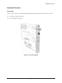
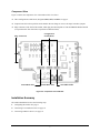
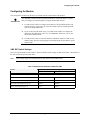
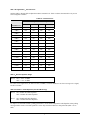
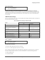
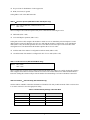
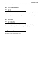
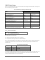
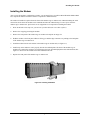
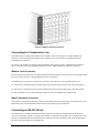
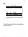
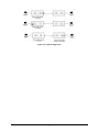
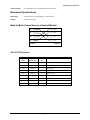
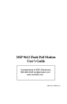
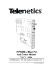
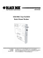
February 2004 0049-0519-500 MD1980C Fast Poll RM Rack-Mount Modem Contents CHAPTER 1 INTRODUCTION..................................................................................................................3 FEATURES ........................................................................................................................................................4 APPLICATIONS ..................................................................................................................................................4 ANCILLARY DOCUMENTATION .........................................................................................................................5 CHAPTER 2 INSTALLATION ...................................................................................................................6 UNPACKING YOUR HARDWARE ........................................................................................................................6 ADDITIONAL ITEMS YOU NEED ........................................................................................................................6 HARDWARE OVERVIEW ....................................................................................................................................7 Front View ...................................................................................................................................................7 Component View..........................................................................................................................................8 INSTALLATION SUMMARY ................................................................................................................................8 CONFIGURING THE MODEM ..............................................................................................................................9 SW1 DIP Switch Settings.............................................................................................................................9 SW2 DIP Switch Settings...........................................................................................................................11 SW3 DIP Switch Settings...........................................................................................................................14 INSTALLING THE MODEM ...............................................................................................................................17 CONNECTING TO A TRANSMISSION LINE.........................................................................................................18 Modular Jack Connectors .........................................................................................................................18 Mass Termination Connector ....................................................................................................................18 CONNECTING AN RS-232 DEVICE...................................................................................................................18 LEDS .............................................................................................................................................................19 LOOPBACK CONTROL SWITCH ........................................................................................................................19 APPENDIX A TROUBLESHOOTING ....................................................................................................22 PROBLEM SOLVING ........................................................................................................................................21 APPENDIX B SPECIFICATIONS............................................................................................................23 GENERAL SPECIFICATIONS .............................................................................................................................22 MECHANICAL SPECIFICATIONS .......................................................................................................................23 BACK-TO-BACK CONNECTIONS TO A SECOND MODEM ..................................................................................23 RS-232 (RTU) Interface.............................................................................................................................23 ENVIRONMENTAL SPECIFICATIONS .................................................................................................................24 APPENDIX C COMPLIANCES................................................................................................................26 FCC REQUIREMENTS FOR TELEPHONE-LINE EQUIPMENT ..............................................................................25 CERTIFICATION NOTICE FOR EQUIPMENT USED IN CANADA ..........................................................................25 NORMAS OFICIALES MEXICANAS (NOM) ELECTRICAL SAFETY STATEMENT INSTRUCCIONES DE SEGURIDAD ....................................................................................................................26 Page ii Chapter 1 Introduction C ongratulations for purchasing the finest industrial-grade fast-poll rack-mount modem available. The BLACK BOX® MD1980C modem is a 9600/4800/0-1800 bps rack-mount modem designed for 4-wire, full-duplex or 2-wire, half-duplex operation over a voice-band leased line. The modem is designed utilizing the latest digital-signal processing (DSP) technology to achieve high performance. The modem employs Black Box’s proprietary modulation and encoding scheme to achieve fast modem training time. It is also backward compatible with Bell 202 modems. The modem can be installed in a BLACKBOX® Modem Rack II (p/n RM421A) from Black Box Corporation. It can also be installed in a DSP9612 Data Shelf from Telenetics Corporation or an RM16M Universal Data Shelf from Motorola/UDS. The modem occupies only one rack slot, eliminating the hassle of equipment trays and power bricks required for “Plastic Box” modems. The modem is powered from the modem cage or modem rack. The BLACK BOX® MD1980C modem is ideally suited for multi-point communication systems that require fast response time, short training time, and low throughput delay. The MD1980C is the most technologically advanced rack-mount modem on the market. This User’s Guide is designed to let you get your modem “up and running” as quickly as possible. It contains all the information you need to install and configure your modem. It also contains troubleshooting information in the unlikely event you encounter a problem with your modem. Page 3 Features Though functionally similar to commercial modems, the MD1980C provides the following unique features that make it well suited for utility and industrial applications. Requires only one rack slot. Operates over voice-band conditioned or unconditioned leased line and pilot wires. Operates without human intervention, making it ideal for unmanned locations. Works within an extended temperature range of -40ºC to +85ºC. Designed with coupling transformers for high-voltage isolation and common mode noise rejection in industrial and commercial environments. Asynchronous data rates (selectable) of 9600, 4800, and 0-1800 bps. Easily accessible DIP switches for user configuration and option selection. Local analog, local digital, and remote digital loopback diagnostics. Applications The BLACK BOX® MD1980C modem is designed for point-to-point and multipoint data communications. Figure 1-1 shows a typical multipoint configuration. Figure 1-1. Network of Multipoint Configuration There are a number of factors that can affect the network’s and modem’s operation and performance. These include: Operating speed 2-wire or 4-wire configuration Transmission line characteristics, noise, and line impairments Network configuration (point-to-point or multipoint) Number of nodes on the network Page 4 Ancillary Documentation Ancillary Documentation For information about the Black Box Modem Rack II, refer to the documentation that came with it. Page 5 Chapter 2 Installation T his chapter describes how to install the modem. Unpacking Your Hardware Your package should include: At least one BLACK BOX® MD1980C modem This User’s Guide If your package contents are damaged or missing, please contact your place of purchase immediately. Additional Items You Need To use your modem, you need the following additional items: A BLACK BOX® Modem Rack II (p/n RM421A). (Or a DSP9612 Data Shelf from Telenetics Corporation or RM16M Universal Data Shelf from Motorola/UDS) A two- or four-wire transmission line or leased line Page 6 Hardware Overview Hardware Overview Front View Figure 2-1 shows a front view of the BLACK BOX® MD1980C modem. Starting from the top, this view shows: A loopback test switch. See page 19. A set of eight LEDs. See page 19. Figure 2-1. Front View of Modem Page 7 Component View Figure 2-2 shows the component view of the modem. This view shows: Three configuration switch blocks, designated SW1, SW2, and SW3. See page 9. Jumpers located in various positions on the modem. Do not change or remove the straps from these jumpers. Edge connectors at the back of the modem, which plug into the backplane of a BLACK BOX® Modem Rack II (or equivalent rack from Telenetics Corporation or Motorola/UDS). Configuration Switch Blocks Edge Connectors Switch Block SW2 Switch Block SW3 Switch Block SW1 Figure 2-2. Component View of Modem Installation Summary The modem installation involves the following steps: 1. Configuring the modem. See page 9.. 2. Connecting to a transmission line. See page 18. 3. Connecting an RS-232 device. See page 18. Page 8 Configuring the Modem Configuring the Modem You configure the modem using the three sets of DIP switches on the bottom of the modem. , IMPORTANT It is important to follow the three steps described below, in the order shown, to ensure that you configure your modem properly using the modem DIP switches: 1. Use DIP switch 3 (SW3) to configure the modem for your host DTE interface and network topology. Using SW3, you select the modem to operate in high-speed fastpoll or low-speed (FSK) mode. 2. If you set SW3 for FSK mode in step 1, use DIP switch 2 (SW2) to configure the modem for either Bell 202T or ITU-T V.23 compatibility. Otherwise, you can use the modem in fallback mode. 3. Use DIP switch 1 (SW1) to select the modem’s transmitter output level and receiver dynamic range. The SW1 settings apply for both high-speed fast-poll and low-speed (FSK) modes. SW1 DIP Switch Settings SW1 is an 8-position DIP switch. Table 2-1 shows the modem switch settings for DIP switch SW1. A description of the SW1 switch settings follows the table. Note: SW1 settings apply for both high-speed fast-poll and low-speed (FSK) modes Table 2-1. Modem Switch Settings for DIP Switch SW1 Switches Switch Settings ON SW1-1 − 1-4: Transmit Level (page 10) OFF (Default) (see Table 2-2 on page 10) SW1-5: Receiver Dynamic Range (page 10) −10 to −43 dBm +3 to −30 dBm SW1-6: TX Cable Equalizer (page 10) Enabled Disabled SW1-7: RX Cable Equalizer (page 10) Enabled Disabled SW1-8: Anti-streaming (page 11) Active Inactive Page 9 SW1-1 through SW1-4 − Transmit Level Switches SW1-1 through SW1-4 adjust the modem’s transmit level. Table 2-2 shows the transmit levels you can select using these switches. Table 2-2. Transmit Levels SW1 through SW4 Switch Settings Transmit Level SW1-1 SW1-2 SW1-3 SW1-4 0 dBm OFF OFF OFF OFF −1 dBm OFF OFF OFF ON −2 dBm OFF OFF ON OFF −3 dBm OFF OFF ON ON −4 dBm OFF ON OFF OFF −5 dBm OFF ON OFF ON −6 dBm OFF ON ON OFF −7 dBm OFF ON ON ON −8 dBm ON OFF OFF OFF −9 dBm ON OFF OFF ON −10 dBm ON OFF ON OFF −11 dBm ON OFF ON ON −12 dBm ON ON OFF OFF −13 dBm ON ON OFF ON −14 dBm ON ON ON OFF +3 dBm ON ON ON ON SW1-5 − Receiver Dynamic Range SW1-5 ON = −10 to −43 dBm OFF = +3 to −30 dBm For a low receive signal level, set SW1-5 to ON (−43 dBm ). For short distances or to select a strong receive signal, set SW1-5 to OFF. SW1-6 and SW1-7 − Cable Equalizer (Fast-Poll Mode Only) SW1-6 ON = Enable TX Cable Equalizer OFF = Disable TX Cable Equalizer SW1-7 ON = Enable RX Cable Equalizer OFF = Disable RX Cable Equalizer To improve or extend the modem’s polling performance, use the fixed Compromise Cable Equalizer when polling on long metallic circuits. The cable equalizer is active only when the modem is in fast-poll mode (SW3-1 set to OFF). Page 10 Configuring the Modem SW1-8 − Anti-streaming SW1-8 ON = Anti-streaming active OFF = Anti-stream inactive Typically, anti-streaming is used in multi-point applications to prevent a malfunctioning slave modem from occupying the line indefinitely. When anti-streaming is active, the modem can transmit data for a maximum of 27 seconds before the transmitter turns off automatically. The modem then looks for an ON-to-OFF Request To Send (RTS) transition before proceeding with normal operation. Anti-streaming can be selected in either high-speed or low-speed mode. SW2 DIP Switch Settings SW2 is an 8-position DIP switch. Table 2-3 shows the modem switch settings for DIP switch SW2. A description of the SW2 switch settings follows the table. Table 2-3. Modem Switch Settings for DIP Switch SW2 Switches Switch Settings ON OFF (Default) SW2-1: FSK Mode (page 11) V.23 Bell 202 SW2-2: Receiver Squelch (page 12) (valid for FSK mode, 2-wire half-duplex operation only) Turnaround Squelch (Bell 202): 8ms Turnaround Squelch (Bell 202): 0ms Turnaround Squelch (V.23): 150ms Turnaround Squelch (V.23): 0ms SW2-3: FSK Soft Carrier (page 12) Disabled Enabled SW2-4 and SW2-5: FSK RTS-CTS Delay (page 12) (see Table 2-4) SW2-6: FSK CD Delay (page 13) 23ms 6ms SW2-7: Remote Loopback (page 13) Enabled Disabled SW2-8: Reserved (Test Only) (page 13) Test Normal SW2-1 FSK Mode SW2-1 ON = ITU-T V.23 mode OFF = Bell 202 mode The modem has two FSK modes: Bell 202, which supports data rates from 0 to 1800 bps ITU-T V.23, which supports data rates from 0 to 1200 bps SW2-1 configures the modem for either of these FSK modes. Setting SW2-1 to ON selects ITU-T V.23 mode. In this mode, the modem complies with ITU-T (CCITT) recommendation V.23 with the following parameters: Mode 2 modulation only No backward channel Page 11 No provisions for disablement of echo suppressors DTR (circuit 108) is ignored Setting SW2-1 OFF selects Bell 202 mode. SW2-2 Receiver Squelch (FSK Mode 2-Wire Half-Duplex Only) SW2-2 ON = 8ms for Bell 202, 150ms for ITU-T V.23 OFF = 0ms SW2-2 configures the turnaround squelch delay and is valid when the following are active: FSK mode (SW3-1 ON) 2-wire half-duplex operation (SW3-7 ON) Setting this switch to OFF configures the modem to enable its receiver immediately after the Request To Send (RTS) signal is turned off. When this switch is set to OFF and the modem is configured for 2-wire, half-duplex mode (SW3-7 ON), the modem squelches the receiver after RTS is turned off to prevent far-end echoes from causing data errors. The duration that the modem squelches the receiver is either: 8 milliseconds if the modem is configured for Bell 202 mode (SW2-1 OFF) 150 milliseconds if the modem is configured for ITU-T V.23 mode (SW2-1 ON) SW2-3 FSK Soft Carrier (Bell 202 FSK Mode Only) SW2-3 ON = None OFF = 8ms SW2-3 controls the soft carrier and is valid for Bell 202 FSK mode only (SW2-1 set to OFF). Setting this switch to OFF configures the modem to transmit a 900 Hz soft carrier to the remote modem for 8 milliseconds after RTS is turned off. Setting this switch to ON prevents the modem from transmitting a soft carrier after RTS is turned off. SW2-4 and SW2-5 RTS-CTS Delay (Bell 202 Mode Only) Switches SW2-4 and SW2-5 determine the duration of the RTS-CTS delay in Bell 202 mode. Table 2-4 shows how to set these switches to select the appropriate setting. Table 2-4. RTS-CTS Delay Settings in Bell 202 Mode To Select a Delay of… Set SW2-4 to… And Set SW2-5 to… 8ms OFF OFF 33ms OFF ON 59ms ON OFF 219ms ON ON Page 12 Configuring the Modem When the modem is configured for V.23 operation (SW2-1 ON), the RTS-CTS delay is fixed at 33 ms. SW2-6 FSK CD Delay (Bell 202 Mode Only) SW2-6 ON = 23ms OFF = 6ms SW2-6 selects the FSK CD delay and is valid when Bell 202 mode is active (SW2-1 OFF). Setting SW2-6 ON configures the modem to turn on CD 23 milliseconds after it detects a valid carrier signal. Setting this switch to OFF configures the modem to turn on CD 6 milliseconds after it detects a valid carrier signal. This switch setting is deactivated when the modem is configured for V.23 mode (SW2-1 ON) and a delay of 18 milliseconds is used instead. SW2-7 Remote Loopback SW2-7 ON = Loopback enabled OFF = Loopback disabled During instances of channel noise, the modem may mistaken a received preamble as a request to go into remote digital loopback. Setting SW2-7 to OFF prevents the modem from participating in a remote digital loopback with another modem. SW2-7 does not prevent the modem from sending a remote digital loopback request to a remote modem. SW2-8 − Reserved (Test Only) SW2-8 Must be OFF SW2-8 must be in the OFF position for normal operation. Page 13 SW3 DIP Switch Settings SW3 is a 10-position DIP switch. Table 2-5 shows the modem switch settings for DIP switch SW3. A description of the SW3 switch settings follows the table. Table 2-5. Modem Switch Settings for DIP Switch SW3 Switches Switch Settings ON OFF (Default) SW3-1: Fast Poll/FSK (page 14) FSK Fast Poll Auto-Rate SW3-2: Data Rate (page 15) 4800 bps 9600 bps SW3-3: Async Character (page 15) 11 bits 10 bits SW3-4: Auto RTS (page 15) Enabled Disabled SW3-5: Transmitter Termination (page 15) Switched by RTS 600 Ω SW3-6: Reserved (Test Only) (page 16) Test Normal SW3-7: 2- or 4-wire (page 16) 2-wire, half-duplex 4-wire, full-duplex SW3-8: Carrier Control (page 16) Constant Switched SW3-9: Rx Termination (page16) 600 Ω High Rx Impedance SW3-10: Signal Ground and Earth Ground Option (page 16) Connected Separated SW3-1 − Fast Poll Auto Rate/FSK SW3-1 ON = Low-Speed Mode (FSK) OFF = High-Speed Mode (Fast Poll) The modem has two operating modes: FSK mode, which supports data rates from 0 to 1800 bps. Fast-poll mode, which supports data rates of 4800 and 9600 bps. SW3-1, along with the Data Rate Selector (DRS) pin on the modem’s RS-232 connector, configures the modem for either FSK or fast-poll mode. Table 2-6 shows how SW3-1 and the DRS signal configure the modem for these operating modes. Table 2-6. Modem Operating Mode To Select… Set SW3-1 to… And the DRS Signal… Fast-poll mode OFF Is not connected or is set HIGH FSK mode OFF Is set LOW FSK mode ON Doesn’t care You should use the DRS signal in RTS control mode. It does not work in either constant carrier mode (SW3-8 set to ON) or in the auto-RTS mode (SW3-4 set to ON). The DRS signal is only sampled when the transmitter is idle (when not sending a preamble, data, or a turn-off sequence). Page 14 Configuring the Modem Note that DRS controls both the transmitter and receiver. If DRS changes states while the modem is receiving a preamble, data, or a turn-off sequence, the state of the receiver is unknown until the carrier drops and a new preamble is received. We recommend that DRS does not change states until both the local and remote modems’ transmitters are in the idle state. When they are, both the local and remote modems’ DRS signal should change states. SW3-2 − Data Rate (Fast-Poll Mode Only) SW3-2 ON = 4800 bps OFF = 9600 bps SW3-2 configures the modem speed. When the modem is in high-speed fast-poll mode (SW3-1 OFF), setting SW32 ON selects 4800 bps, while setting SW3-2 OFF selects 9600 bps. SW3-3 − Async Character (Fast-Poll Mode Only) SW3-3 ON = 11 bits OFF = 10 bits Switch SW3-3 selects whether the async character is 10 or 11 bits long. When the modem is in high-speed fast-poll mode (SW3-1 OFF), setting SW3-3 ON selects an 11-bit async characters, while setting SW3-3 OFF selects a 10bit async character. SW3-4 − Auto RTS (Fast-Poll Mode Only) SW3-4 ON = Enable Auto RTS OFF = Disable Auto RTS For data terminals that do not support hardware RTS, set SW3-4 to ON to enable auto RTS mode. In this mode, TXD is detected at the modem and an internal RTS signal is turned ON. After training completes, the TXD is transmitted to the remote modem. The transmitter turns off if no TXD is detected after 1 character length of idle time. Auto RTS is used in fast-poll mode only (SW3-1 set to OFF). SW3-5 − Transmitter Termination SW3-5 ON = Switched by RTS OFF = 600 Ω SW3-5 is used for multi-point configuration networks. When multiple modems are connected on the same metallic circuit: The transmitter termination should be of high impedance if the modem is not transmitting. The transmitter is only terminated with 600 ohms when RTS is asserted. This configuration should be used for all slave modems to prevent the transmitting modem from being unnecessarily burdened. To select this configuration, set SW3-5 ON on the slave modems. If you use the modem with transmission lines that are transformer-coupled or with an impedance-isolated network (such as a transformer bridge), set SW3-5 OFF for proper operation. Page 15 SW3-6 − Reserved (Test Only) SW3-6 Must be OFF SW3-6 must be in the OFF position for normal operation. SW3-7 − 2-/4-Wire Operation SW3-7 ON = 2-Wire, Half-Duplex Mode OFF = 4-Wire, Full-Duplex Mode SW3-7 configures the modem for 4-wire full-duplex or 2-wire half-duplex operation. SW3-8 − Carrier Control SW3-8 ON = Constant OFF = Switched SW3-8 selects either constant or switched carrier. Constant carrier allows DTEs, such as asynchronous dumb terminals or RTUs, to operate with modems, without the input RTS signal. When constant carrier mode is enabled (SW3-8 set to ON), the modem forces the transmit carrier active and the RTS-CTS delay is minimum (<0.5 ms.). You can use constant carrier in 4-wire, point-to-point or multi-point applications (from master to slave modems). In switched-carrier mode (SW3-8 set to OFF), the RTS/CTS delay is active. SW3-9 − RX Termination SW3-9 ON = Enable Rx Termination OFF = Disable Rx Termination SW3-9 selects whether RX termination is enabled for a modem. If you set this switch ON, the receiver is terminated with 600 Ω. If you set this switch OFF, the receiver is not terminated. SW3-10 − Grounding Option SW3-10 ON = Signal Ground and Earth Ground are Connected OFF = Signal Ground and Earth Ground are Separated Page 16 Installing the Modem Installing the Modem After you set the modem’s configuration switches, you can install it in a slot within a BLACK BOX® Modem Rack II (or equivalent modem rack from Telenetics Corporation or Motorola/UDS). The modem is installed or replaced from the front of the modem cage or modem rack, without disturbing the cable connections on the back. The modem can be installed and removed without having to remove power from the modem cage or modem rack. Special tools or test equipment are not required for installing the modem. 1. Wear an antistatic wrist strap over your wrist on your bare skin (not over a shirt or jacket). 2. Remove the wrapping protecting the modem. 3. Remove the front panel of the modem cage or modem rack and pick an empty slot. 4. Hold the modem so the front panel LEDs are facing you and the edge connectors are pointing to the backplane of the modem cage or modem rack. 5. Install the modem into the selected slot in the modem cage or modem rack (see Figure 2-3). 6. Push firmly on the modem to seat it properly into the slot and backplane. The back of the modem cage or modem rack contains the connectors for interfacing to the Date Terminal Equipment and communications line. Figure 2-4 shows how the modems look when installed in the rack. 7. Replace the front panel of the modem cage or modem rack. Figure 2-3. Installing the Modem Page 17 Figure 2-4. Modems Installed in the Rack Connecting to a Transmission Line The modem cage or modem rack has different Telco options. Your version may have 16 8-pin modular jack connectors, one for each slot in the modem cage or modem rack. It may also have an optional 50-pin masstermination Telco connector. To connect your modem to a leased line using the modular jack connectors, refer to “Modular Jack Connectors,” below. To use the 50-pin mass-termination connector, refer to “Mass Termination Connector” on page 18. Modular Jack Connectors The rear panel of the modem cage or modem rack has an 8-pin RJ-45 jack for each slot. After you install the modem into a slot, connect the slot’s corresponding RJ-45 jack to a leased line. Leased lines have four contacts: a transmit (Tx) pair and a receive (Rx) pair. For communication to occur: The Rx line of the modem cage or modem rack RJ-45 jack must connect to the Tx line of the other modem. The Tx line of the modem cage or modem rack RJ-45 jack must connect to the Rx line of the other modem. For more information, refer to the documentation that came with your modem cage or modem rack. Mass Termination Connector As an option, a 50-pin mass-termination connector can be used as the Telco connection for the modem(s). For more information, refer to the documentation that came with your modem cage or modem rack. Connecting an RS-232 Device The modem cage or modem rack has different RS-232 options for accepting an attached RS-232 (RTU) device. Your version may have a female, 25-pin RS-232 connector for each slot in the modem cage or modem rack. It may also have an optional 50-pin mass-termination Telco connector. For more information, refer to the documentation that came with your modem cage or modem rack. Page 18 LEDs LEDs The front panel of the modem provides the LEDs shown in Table 2-7. Table 2-7. Modem LEDs LED Color Description Power Green Power RTS Yellow Request To Send CTS Yellow Clear To Send TxD Yellow Transmit Data RxD Yellow Receive Data DCD Yellow Carrier Detect ALB Red* Analog Loopback DLB Red* Digital Loopback * When the modem is in remote loopback, both the ALB and DLB LEDs go ON. Loopback Control Switch The front panel of the modem has a push button for initiating the following loopback diagnostic tests: Local analog loopback started by pressing the button one time. Local digital loopback started by pressing the button two times. Remote digital loopback set the local modem’s RTS signal to low. Then press the remote modem’s diagnostics button three times and raise the local modem’s RTS signal to start the test. The ALB and DLB LEDs go ON when the modem is in remote digital loopback. This test is only available in Fast Poll mode only. Figure 2-6 illustrates these three diagnostics. Page 19 Figure 2-6. Loopback Diagnostics Page 20 Appendix A Troubleshooting I n the event you encounter a problem using your Black Box modem, refer to the troubleshooting information in this appendix. To troubleshoot the power supply and backplane on the modem cage or modem rack, refer to the documentation that came with your modem cage or modem rack. , IMPORTANT If you encounter a problem with your modem, be sure the modem switches are set to the appropriate positions. If a switch is halfway between an on and off setting, the modem will not operate properly. Problem Solving Table A-1 offers troubleshooting solutions for modem problems. Table A-1. Troubleshooting Suggestions If… Perform These Procedures… Modem does not respond and all LEDs are off. Check the modem cage or modem rack power supply module(s). Modem does not receive data, and the DCD and RxD LEDs are off. The receive line pair may be disconnected from the modem. Make sure the transmission line connection to the rear panel of the modem cage or modem rack is accurate and secure. The receive signal level may be below the CD threshold. Set SW1-5 ON to see whether configuring the modem for a −43 dBm threshold resolves the problem. The RTS, CTS, and TxD LEDs do not blink. The attached terminal or DTE may not be sending data to the modem. Verify that data is being transmitted. If data is being transmitted, make sure the RS-232 cable is sound and securely connected to the modem and terminal or DTE. Page 21 Appendix B Specifications General Specifications Data rate: 9600, 4800, or 0-1800 bps asynchronous Data format: 8 or 9 data bits with 1 or more stop bits DTE interface: EIA RS-232 or V.24 compatible Line conditions: TELCO Voice band 4- or 2-wire leased line, conditioned or unconditioned Private metallic circuits up to 9.5 miles (24 AWG) without cable equalizer. Up to 15.0 miles (24 AWG) with TX and RX cable equalizer Operating modes: 2-wire half-duplex or 4-wire full-duplex Modulation: High-speed fast poll – Black Box proprietary FSK, Bell 202T compatible • Mark = 1200 Hz • Space = 2200 Hz • Soft Carrier = 900 Hz Equalizer: Automatic, adaptive RTS-CTS Delay: 23 ms. (fast poll) 8, 33, 59, or 219 ms (FSK) Receiver dynamic range: 0 to –30 dBm or –10 to –43 dBm Operating temperature: -40°C to +85°C Surge protection: Leased line, up to 15KV Carrier Control: Constant or switched, DIP switch selectable Carrier loss recovery: Train on Data Throughput delay: Less than 10 milliseconds for fast polling. Auto RTS: Support DTE without hardware RTS (high speed only) Page 22 Mechanical Specifications Anti-Streaming: 27-second timer to prevent transmitter lock-up network Mechanical Specifications Dimensions: 9 inches deep x 6.25 inches high x .87 inches thick Weight: 8 ounces (card only) Back-to-Back Connections to a Second Modem Rx Rx Rx Rx Tx Tx Tx Tx Modem 1 Modem 2 RS-232 (RTU) Interface Signal Name Modem Input/Output DB25 Pin Description Earth GND 1 Earth Ground TXD Input 2 Transmit Data RXD Output 3 Receive Data RTS Input 4 Request To Send CTS Output 5 Clear To Send DSR Output 6 Data Set Ready (Modem Ready) SG - 7 Signal Ground DCD Output 8 Data Carrier Detected DTR Input 20 Data Terminal Ready (Host Ready) Page 23 Environmental Specifications Operating temperature: -40 to + 85o C Storage temperature: -40 to +125o C Operating humidity: 5 to 95 %, non-condensing. Isolation: 3750 V RMS Surge protection: Leased line up to 15K VA Page 24 Appendix C Compliances FCC REQUIREMENTS FOR TELEPHONE-LINE EQUIPMENT 1. The Federal Communications Commission (FCC) has established rules which permit this device to be directly connected to the telephone network with standardized jacks. This equipment should not be used on party lines or coin lines. 2. If this device is malfunctioning, it may also be causing harm to the telephone network; this device should be disconnected until the source of the problem can be determined and until the repair has been made. If this is not done, the telephone company may temporarily disconnect service. 3. If you have problems with your telephone equipment after installing this device, disconnect this device from the line to see if it is causing the problem. If it is, contact your supplier or an authorized agent. 4. The telephone company may make changes in its technical operations and procedures. If any such changes affect the compatibility or use of this device, the telephone company is required to give adequate notice of the changes. 5. If the telephone company requests information on what equipment is connected to their lines, inform them of: a. The telephone number that this unit is connected to. b. The ringer equivalence number. c. The USOC jack required: RJ-11C. d. The FCC registration number. Items (b) and (d) can be found on the unit’s FCC label. The ringer equivalence number (REN) is used to determine how many devices can be connected to your telephone line. In most areas, the sum of the RENs of all devices on any one line should not exceed five (5.0). If too many devices are attached, they may not ring properly. 6. In the event of an equipment malfunction, all repairs should be performed by your supplier or an authorized agent. It is the responsibility of users requiring service to report the need for service to the supplier or to an authorized agent. CERTIFICATION NOTICE FOR EQUIPMENT USED IN CANADA The Canadian Department of Communications label identifies certified equipment. This certification means that the equipment meets certain telecommunications-network protective, operation, and safety requirements. The Department does not guarantee the equipment will operate to the user’s satisfaction. Before installing this equipment, users should ensure that it is permissible to be connected to the facilities of the local telecommunications company. The equipment must also be installed using an acceptable method of connection. In some cases, the company’s inside wiring associated with a single-line individual service may be extended by means of a certified connector assembly (extension cord). The customer should be aware that compliance with the above conditions may not prevent degradation of service in some situations. Page 25 Repairs to certified equipment should be made by an authorized Canadian maintenance facility—in this case, your supplier. Any repairs or alterations made by the user to this equipment, or equipment malfunctions, may give the telecommunications company cause to request the user to disconnect the equipment. Users should ensure for their own protection that the electrical ground connections of the power utility, telephone lines, and internal metallic water pipe system, if present, are connected together. This precaution may be particularly important in rural areas. CAUTION: Users should not attempt to make such connections themselves, but should contact the appropriate electric inspection authority, or electrician, as appropriate. The LOAD NUMBER (LN) assigned to each terminal device denotes the percentage of the total load to be connected to a telephone loop which is used by the device, to prevent overloading. The termination on a loop may consist of any combination of devices, subject only to the requirement that the total of the load numbers of all the devices does not exceed 100. FEDERAL COMMUNICATIONS COMMISSION AND CANADIAN DEPARTMENT OF COMMUNICATIONS RADIO FREQUENCY INTERFERENCE STATEMENTS This equipment generates, uses, and can radiate radio frequency energy and if not installed and used properly, that is, in strict accordance with the manufacturer’s instructions, may cause interference to radio communication. It has been tested and found to comply with the limits for a Class A computing device in accordance with the specifications in Subpart B of Part 15 of FCC rules, which are designed to provide reasonable protection against such interference when the equipment is operated in a commercial environment. Operation of this equipment in a residential area is likely to cause interference, in which case the user at his own expense will be required to take whatever measures may be necessary to correct the interference. Changes or modifications not expressly approved by the party responsible for compliance could void the user’s authority to operate the equipment. This digital apparatus does not exceed the Class A limits for radio noise emission from digital apparatus set out in the Radio Interference Regulation of the Canadian Department of Communications. Le présent appareil numérique n’émet pas de bruits radioélectriques dépassant les limites applicables aux appareils numériques de la classe A prescrites dans le Règlement sur le brouillage radioélectrique publié par le ministère des Communications du Canada. NORMAS OFICIALES MEXICANAS (NOM) ELECTRICAL SAFETY STATEMENT INSTRUCCIONES DE SEGURIDAD 1. Todas las instrucciones de seguridad y operación deberán ser leídas antes de que el aparato eléctrico sea operado. 2. Las instrucciones de seguridad y operación deberán ser guardadas para referencia futura. 3. Todas las advertencias en el aparato eléctrico y en sus instrucciones de operación deben ser respetadas. 4. Todas las instrucciones de operación y uso deben ser seguidas. 5. El aparato eléctrico no deberá ser usado cerca del agua—por ejemplo, cerca de la tina de baño, lavabo, sótano mojado o cerca de una alberca, etc. 6. El aparato eléctrico debe ser usado únicamente con carritos o pedestales que sean recomendados por el fabricante. 7. El aparato eléctrico debe ser montado a la pared o al techo sólo como sea recomendado por el fabricante. Page 26 NORMAS OFICIALES MEXICANAS (NOM) ELECTRICAL SAFETY STATEMENT INSTRUCCIONES DE SEGURIDAD 8. Servicio—El usuario no debe intentar dar servicio al equipo eléctrico más allá a lo descrito en las instrucciones de operación. Todo otro servicio deberá ser referido a personal de servicio calificado. 9. El aparato eléctrico debe ser situado de tal manera que su posición no interfiera su uso. La colocación del aparato eléctrico sobre una cama, sofá, alfombra o superficie similar puede bloquea la ventilación, no se debe colocar en libreros o gabinetes que impidan el flujo de aire por los orificios de ventilación. 10. El equipo eléctrico deber ser situado fuera del alcance de fuentes de calor como radiadores, registros de calor, estufas u otros aparatos (incluyendo amplificadores) que producen calor. 11. El aparato eléctrico deberá ser connectado a una fuente de poder solo del tipo descrito en el instructivo de operación, o como se indique en el aparato. 12. Precaución debe ser tomada de tal manera que la tierra fisica y la polarización del equipo no sea eliminada. 13. Los cables de la fuente de poder deben ser guiados de tal manera que no sean pisados ni pellizcados por objetos colocados sobre o contra ellos, poniendo particular atención a los contactos y receptáculos donde salen del aparato. 14. El equipo eléctrico debe ser limpiado únicamente de acuerdo a las recomendaciones del fabricante. 15. En caso de existir, una antena externa deberá ser localizada lejos de las lineas de energia. 16. El cable de corriente deberá ser desconectado del cuando el equipo no sea usado por un largo periodo de tiempo. 17. Cuidado debe ser tomado de tal manera que objectos liquidos no sean derramados sobre la cubierta u orificios de ventilación. 18. Servicio por personal calificado deberá ser provisto cuando: a. El cable de poder o el contacto ha sido dañado; u b. Objectos han caído o líquido ha sido derramado dentro del aparato; o c. El aparato ha sido expuesto a la lluvia; o d. El aparato parece no operar normalmente o muestra un cambio en su desempeño; o e. El aparato ha sido tirado o su cubierta ha sido dañad Page 27