1
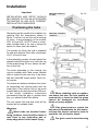
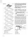
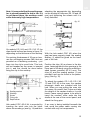
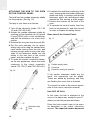
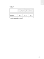
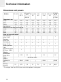
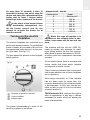
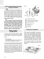
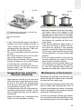
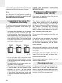
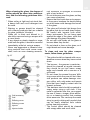
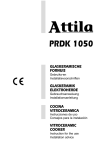
INSTALLATION INSTRUCTIONS
AND RECOMMENDATIONS FOR USE AND MAINTENANCE
GLASS GAS HOBS
EINBAU-ANLEITUNG
UND EMPFEHLUNGEN FÜR GEBRAUCH UND INSTANDHALTUNG
GAS-KOCHFELDER AUF GLAS
INSTRUCTIONS POUR L’INSTALLATION
ET RECOMMANDATIONS D’UTILISATION ET D’ENTRETIEN
PLAQUES DE CUISSON
CG.1 4G / CG.1 3G 1P
CG Lux-60 4G / CG Lux-70 4G / CG Lux-70 4G AI AL
CG Lux-70 5G / CG Lux-60 4G Al AL / CG Lux-70 5G Al AL
CG Lux-70 5G AI TR AL / CG Lux-70 5G TR / CGC 4G
CGC 4G AI AL / CG Lux-75 2G AI TR AL / CG Lux-86 3G AI TR AL
CG Lux-60 4G AI / CG Lux-70 4G AI / CG Lux-70 5G AI
CG Lux-70 5G AI TR / CG Lux-75 2G AI TR / CG Lux-86 3G AI TR
VR 90 4G AI TR AL / VR 90 4G AI TR
Contents / Inhalt / Table des Matières
GB
Introduction
User Guide
DE
Page 5
10
Präsentation
Hinweise zum Gebrauch
Seite 5
31
Installation
Positioning the hobs
Positioning the oven
Anchoring the hob
Connecting the gas
Connecting the electricity
Gas conversion
11
11
12
12
15
16
16
Einbau
Einbauort für die Kochfelder
Einbauort für den Ofen
Verankerung des Kochfelds
Gasanschluss
Elektrischer Anschluss
Umstellung auf andere Gasart
32
32
33
33
37
38
38
Technical information
Dimensions and powers
Technical data
18
18
20
Technische Information
Abmessungen und Leistungen
Technische Daten
40
40
42
Use and Maintenance
Before starting for the first time
Igniting the burners
Turning on the electric hotplates
Anti-accidental turn mechanism on
the gas controls
Safety sistem components
Using the hotplates
Suggestions for effective use
the burners
Maintenance of the burners
Suggestions for effective use
of the hotplates
Maintenance of the electric
hotplates
Cleaning and care
Reminder
21
21
21
23
43
26
26
29
Gebrauch und Instandhaltung
Besondere Vorbedingungen für die
Inbetriebnahme
Anzünden der Gasbrenner
Einschalten der elektrischen Kochzonen
Schutz gegen versehentliches Drehen
der Gashähne
Bestandteile eines Systems
für sicheren Gebrauch
Gebrauch der Kochzonen
Tipps für den korrekten Gebrauch
der Gasbrenner
Instandhaltung der Brenner
Tipps für die korrekte Verwendung
der Kochfelder
Elektrische Kochzonen
Reinigung und Pflege
If something doesn’t work
30
Im Störungsfall
53
23
24
24
25
25
25
43
43
45
46
46
46
47
48
48
49
49
3
FR
Présentation
Guide d’utilisation
4
Page 5
54
Installation
Logement des tables de cuisson
Logement du four
Ancrage de la table de cuisson
Raccordement au gaz
Branchement électrique
Adaptation du gaz
55
55
56
56
60
60
61
Informations techniques
Dimensions et puissances
Caractéristiques techniques
62
62
64
Utilisation et entretien
Conditions spéciales avant la
mise en marche
Allumage des brûleurs
Allumage des plaques électriques
Système de blocage des
commandes de gaz
Composants d’un système
de sécurité
Utilisation des tables de cuisson
Recommandations pour une bonne
utilisation des brûleurs
Entretien des brûleurs
Recommandations pour une bonne
utilisation des plaques
Plaques électriques
Nettoyage et entretien
Rappel
65
Si quelque chose ne fonctionne pas
74
65
65
67
67
68
68
70
69
70
70
70
73
Introduction / Einführung / Présentation
1
2
1
2
3
4
3
4
CG.1 4G
GB
DE
FR
1 Semi-rapid burner 1,500 Kcal/h -1.75 kW.
2 Auxiliary burner 860 Kcal/h - 1 kW.
3 Semi-rapid burner 1,500 Kcal/h -1.75 kW.
4 Rapid burner 2,580 Kcal/h -3 kW.
* All the burners have a grid.
* Maximum calorific power: 6,400 Kcal/h - 7.5 kW.
1 Mittel-Brenner mit 1500 kcal/h - 1,75 kW
2 Hilfsbrenner mit 860 kcal/h - 1 kW
3 Mittel-Brenner mit 1500 kcal/h - 1,75 kW
4 Stark-Brenner mit 2580 kcal/h - 3 kW
* Alle Brenner sind mit Stellrost ausgestattet.
* Maximale Wärmeleistung: 6400 Kcal/h - 7,5 kW.
1 Brûleur semi-rapide de 1.500 Kcal/h - 1,75 kW.
2 Brûleur auxiliaire de 860 Kcal/h - 1 kW.
3 Brûleur semi-rapide de 1.500 Kcal/h - 1,75 kW.
4 Brûleur rapide de 2.580 Kcal/h - 3 kW.
* Tous les brûleurs disposent d’une grille.
* Puissance calorifique maximale: 6.400 Kcal/h -7,5 kW.
CG.1 3G 1P
GB 1 Rapid hotplate 1500 W., ø 145 mm.
2 Auxiliary burner 860 Kcal/h - 1 kW.
3 Semi-rapid burner 1,500 Kcal/h -1.75 kW.
4 Rapid burner 2,580 Kcal/h - 3 kW.
* All the burners have a grid.
* Maximum calorific power: 4,900 Kcal/h 5.75 kW.
* Maximum electric power: 1500 watts.
DE
1 Schnellkochzone mit 1500 W, ÿ 145 mm
2 Hilfsbrenner mit 860 kcal/h - 1 kW
3 Mittel-Brenner mit 1500 kcal/h - 1,75 kW
4 Stark-Brenner mit 2580 kcal/h - 3 kW
* Alle Brenner sind mit Stellrost ausgestattet.
* Maximale Wärmeleistung: 4900 Kcal/h 5,75 kW.
* Maximale Elektrische Leistung: 1500 W
FR
1 Plaque rapide de 1.500 W., ø 145 mm.
2 Brûleur auxiliaire de 860 Kcal/h - 1 kW.
3 Brûleur semi-rapide de 1.500 Kcal/h 1,75 kW.
4 Brûleur rapide de 2.580 Kcal/h - 3 kW.
* Tous les brûleurs disposent d’une grille.
* Puissance calorifique maximale:
4.900 Kcal/h - 5,75 kW.
* Puissance électrique maximale: 1.500 Watts.
5
1
2
2
1
5
3
4
3
CG-Lux-60 4G / CG Lux-60 4G Al AL / CG Lux-60
4G AI
GB
DE
FR
CGC 4G / CGC 4G AI AL
GB
1 Rapid burner 2,580 Kcal/h - 3 kW.
2 Semi-rapid burner 1,500 Kcal/h -1.75 kW.
3 Semi-rapid burner 1,500 Kcal/h -1.75 kW.
4 Auxiliary burner 860 Kcal/h - 1 kW.
* All the burners have a grid.
* Maximum calorific power: 6,450 Kcal/h - 7.5 kW.
DE
1 Stark-Brenner mit 2580 kcal/h - 3 kW
2 Mittel-Brenner mit 1500 kcal/h - 1,75 kW
3 Mittel-Brenner mit 1500 kcal/h - 1,75 kW
4 Hilfsbrenner mit 860 kcal/h - 1 kW
* Alle Brenner sind mit Stellrost ausgestattet.
* Maximale Wärmeleistung: 6450 Kcal/h - 7,5 kW.
FR
1 Brûleur rapide de 2.580 Kcal/h - 3 kW.
2 Brûleur semi-rapide de 1.500 Kcal/h - 1,75 kW.
3 Brûleur semi-rapide de 1.500 Kcal/h - 1,75 kW.
4 Brûleur auxiliaire de 860 Kcal/h - 1 kW.
* Tous les brûleurs disposent d’une grille.
* Puissance calorifique maximale: 6.450 Kcal/h - 7,5 kW.
1 Rapid burner 2,580 Kcal/h - 3 kW.
2 Semi-rapid burner 1,500 Kcal/h -1.75 kW.
3 Semi-rapid burner 1,500 Kcal/h -1.75 kW.
4 Auxiliary burner 860 Kcal/h - 1 kW.
5 Burner operating controls.
* All the burners have a grid.
* Maximum calorific power: 6,450 Kcal/h - 7.5 kW.
1 Stark-Brenner mit 2580 kcal/h - 3 kW
2 Mittel-Brenner mit 1500 kcal/h - 1,75 kW
3 Mittel-Brenner mit 1500 kcal/h - 1,75 kW
4 Hilfsbrenner mit 860 kcal/h - 1 kW
5 Bedienregler für die Brenner
* Alle Brenner sind mit Stellrost ausgestattet.
* Maximale Wärmeleistung: 6450 Kcal/h - 7,5 kW.
1 Brûleur rapide de 2.580 Kcal/h - 3 kW.
2 Brûleur semi-rapide de 1.500 Kcal/h - 1,75 kW.
3 Brûleur semi-rapide de 1.500 Kcal/h - 1,75 kW.
4 Brûleur auxiliaire de 860 Kcal/h - 1 kW.
5 Manettes pour l’allumage des brûleurs.
* Tous les brûleurs disposent d’une grille.
* Puissance calorifique maximale: 6.450 Kcal/h - 7,5 kW.
6
4
1
2
1
4
3
5
2
5
3
6
4
6
CG-Lux-70 5G TR / CG Lux-70 5G AI TR AL /
CG Lux -70 5G AI TR
CG-Lux-70 5G / CG Lux-70 5G Al AL / CG Lux -70
5G AI
GB
1 Rapid burner 2,580 Kcal/h - 3 kW.
2 Semi-rapid burner 1,500 Kcal/h -1.75 kW.
3 Semi-rapid burner 1,500 Kcal/h -1.75 kW.
4 Auxiliary burner 860 Kcal/h - 1 kW.
5 Rapid burner 2,580 Kcal/h - 3 kW.
6 Burner operating controls.
* All the burners have a grid.
* Maximum calorific power: 9,020 Kcal/h -10.5 kW.
GB
1 Rapid burner 2,580 Kcal/h - 3 kW.
2 Semi-rapid burner 1,500 Kcal/h -1.75 kW.
3 Semi-rapid burner 1,500 Kcal/h -1.75 kW.
4 Auxiliary burner 860 Kcal/h - 1 kW.
5 Triple crown burner 3,010 Kcal/h - 3.5 kW.
6 Burner operating controls.
* All the burners have a grid.
* Maximum calorific power: 9,450 Kcal/h -11 kW.
DE
1 Stark-Brenner mit 2580 kcal/h - 3 kW
2 Mittel-Brenner mit 1500 kcal/h - 1,75 kW
3 Mittel-Brenner mit 1500 kcal/h - 1,75 kW
4 Hilfsbrenner mit 860 kcal/h - 1 kW
5 Stark-Brenner mit 2580 kcal/h - 3 kW
6 Bedienregler für die Brenner
* Alle Brenner sind mit Stellrost ausgestattet.
* Maximale Wärmeleistung: 9020 Kcal/h -10,5 kW.
DE
1 Stark-Brenner mit 2580 kcal/h - 3 kW
2 Mittel-Brenner mit 1500 kcal/h - 1,75 kW
3 Mittel-Brenner mit 1500 kcal/h - 1,75 kW
4 Hilfsbrenner mit 860 kcal/h - 1 kW
5 Brenner mit Dreifachkranz 3010 kcal/h -3,5 kW
6 Bedienregler für die Brenner
* Alle Brenner sind mit Stellrost ausgestattet.
* Maximale Wärmeleistung: 9450 Kcal/h -11 kW.
FR
1 Brûleur rapide de 2.580 Kcal/h - 3 kW.
2 Brûleur semi-rapide de 1.500 Kcal/h - 1,75 kW.
3 Brûleur semi-rapide de 1.500 Kcal/h - 1,75 kW.
4 Brûleur auxiliaire de 860 Kcal/h - 1 kW.
5 Brûleur rapide de 2.580 Kcal/h - 3 kW.
6 Manettes pour l’allumage des brûleurs.
* Tous les brûleurs disposent d’une grille.
* Puissance calorifique maximale: 9.020 Kcal/h 10,5 kW.
FR
1 Brûleur rapide de 2.580 Kcal/h - 3 kW.
2 Brûleur semi-rapide de 1.500 Kcal/h - 1,75 kW.
3 Brûleur semi-rapide de 1.500 Kcal/h - 1,75 kW.
4 Brûleur auxiliaire de 860 Kcal/h - 1 kW.
5 Brûleur triple couronne de 3.010 Kcal/h - 3,5 kW.
6 Manettes pour l’allumage des brûleurs.
* Tous les brûleurs disposent d’une grille.
* Puissance calorifique maximale: 9.450 Kcal/h 11 kW.
7
1
2
3
4
1
5
3
CG-Lux-70 4G / CG-Lux-70 4G AI AL /
CG Lux -70 4G AI
GB
1 Rapid burner 2,580 Kcal/h - 3 kW.
2 Semi-rapid burner 1,500 Kcal/h -1.75 kW.
3 Semi-rapid burner 1,500 Kcal/h -1.75 kW.
4 Auxiliary burner 860 Kcal/h - 1 kW.
5 Burner operating controls.
* All the burners have a grid.
* Maximum calorific power: 6,450 Kcal/h - 7.5 kW.
CG-Lux-75 2G AI TR AL / CG Lux-75 2G AI TR
GB
DE
DE
FR
1 Stark-Brenner mit 2580 kcal/h - 3 kW
2 Mittel-Brenner mit 1500 kcal/h - 1,75 kW
3 Mittel-Brenner mit 1500 kcal/h - 1,75 kW
4 Hilfsbrenner mit 860 kcal/h - 1 kW
5 Bedienregler für die Brenner
* Alle Brenner sind mit Stellrost ausgestattet.
* Maximale Wärmeleistung: 6450 Kcal/h - 7,5 kW.
1 Brûleur rapide de 2.580 Kcal/h - 3 kW.
2 Brûleur semi-rapide de 1.500 Kcal/h - 1,75 kW.
3 Brûleur semi-rapide de 1.500 Kcal/h - 1,75 kW.
4 Brûleur auxiliaire de 860 Kcal/h - 1 kW.
5 Manettes pour l’allumage des brûleurs.
* Tous les brûleurs disposent d’une grille.
* Puissance calorifique maximale: 6.450 Kcal/h - 7,5 kW.
8
2
FR
1 Triple crown burner 3,010 Kcal/h - 3.5 kW.
2 Triple crown burner 3,010 Kcal/h - 3.5 kW.
3 Burner operating controls.
* All the burners have a grid.
* Maximum calorific power: 6,020 Kcal/h -7 kW.
1 Brenner mit Dreifachkranz 3010 kcal/h -3,5 kW
2 Brenner mit Dreifachkranz 3010 kcal/h -3,5 kW
3 Bedienregler für die Brenner
* Alle Brenner sind mit Stellrost ausgestattet.
* Maximale Wärmeleistung: 6020 Kcal/h -7 kW.
1 Brûleur triple couronne de 3.010 Kcal/h - 3,5 kW.
2 Brûleur triple couronne de 3.010 Kcal/h - 3,5 kW.
3 Manettes pour l’allumage des brûleurs.
* Tous les brûleurs disposent d’une grille.
* Puissance calorifique maximale: 6.020 Kcal/h - 7 kW.
1
2
1
2
3
3
4
4
CG-Lux-86 3G AI TR AL / CG Lux-86 3G AI TR
VR 90 4G AI TR AL / VR 90 4G AI TR
GB
1 Triple crown burner 3,010 Kcal/h - 3.5 kW.
2 Triple crown burner 3,010 Kcal/h - 3.5 kW.
3 Semi-rapid burner 1,500 Kcal/h -1.75 kW.
4 Burner operating controls.
* All the burners have a grid.
* Maximum calorific power: 7,520 Kcal/h -8.75 kW.
GB
1 Triple crown burner 3.010 Kcal/h - 3,5 kW.
2 Auxiliary burner 860 Kcal/h - 1 kW.
3 Semi-rapid burner 1.500 Kcal/h - 1,75 kW.
4 Rapid burner 2.580 Kcal/h - 3 kW.
* All the burners have a grid.
* Maximum calorific power: 7.950 Kcal/h - 9,25 kW.
DE
1 Brenner mit Dreifachkranz 3010 kcal/h -3,5 kW
2 Brenner mit Dreifachkranz 3010 kcal/h -3,5 kW
3 Mittel-Brenner mit 1500 kcal/h - 1,75 kW
4 Bedienregler für die Brenner
* Alle Brenner sind mit Stellrost ausgestattet.
* Maximale Wärmeleistung: 7520 Kcal/h - 8,75 kW.
DE
1 Brenner mit Dreifachkranz 3.010 Kcal/h - 3,5 kW.
2 Hilfsbrenner mit 860 Kcal/h - 1 kW.
3 Mittel-Brenner mit 1.500 Kcal/h - 1,75 kW.
4 Stark-Brenner mit 2.580 Kcal/h - 3 kW.
* Alle Brenner sind mit Stellrost ausgestattet.
* Maximale Wärmeleistung: 7.950 Kcal/h - 9,25 kW.
FR
1 Brûleur triple couronne de 3.010 Kcal/h - 3,5 kW.
FR
2 Brûleur triple couronne de 3.010 Kcal/h - 3,5 kW.
3 Brûleur semi-rapide de 1.500 Kcal/h - 1,75 kW.
4 Manettes pour l’allumage des brûleurs.
* Tous les brûleurs disposent d’une grille.
* Puissance calorifique maximale: 7.520 Kcal/h - 8,75 kW.
1 Brûleur triple couronne de 3.010 Kcal/h - 3,5 kW.
2 Brûleur auxiliaire de 860 Kcal/h - 1 kW.
3 Brûleur semi-rapide de 1.500 Kcal/h - 1,75 kW.
4 Brûleur rapide de 2.580 Kcal/h - 3 kW.
* Tous les brûleurs disposent d’une grille.
* Puissance calorifique maximale: 7.950 Kcal/h - 9,25 W.
9
GB
Guide to Using the Instructions Booklet
Dear customer,
Safety instructions
We are delighted that you have put your
trust in us.
Before first use, you should carefully read
the installation and connection instructions.
We are confident that the new hob that you
have purchased will fully satisfy your
needs.
This modern, functional and practical
model has been manufactured using topquality materials that have undergone
strict quality controls throughout the manufacturing process.
Before installing and using it, we would
ask that you read this Manual carefully and
follow the instructions closely, as this will
guarantee better results when using the
appliance.
Keep this Instruction Manual in a safe
place so that you can refer to it easily and
thus abide by the guarantee conditions.
In order to benefit from this Guarantee, it is
essential that you submit the purchase
receipt together with the Guarantee Certificate.
You should keep the Guarantee
Certificate or, where relevant, the
technical datasheet, together with the
Instruction Manual for the duration of
the useful life of the appliance. It has
important technical information about
the appliance.
10
These hob models may be installed in the
same kitchen furniture units as TEKA
brand ovens.
For your safety, installation should be
carried out by an authorised technician
and should comply with existing installation standards. Likewise, any internal work
on the hob should only be done by TEKA’s
technical staff, including the change of the
flexible supply cable of the appliance.
Please note:
When the hotplates are in operation or have recently been in operation,
some areas will be hot and can burn.
Children should be kept well away.
Installation
Important
GB
Minimum distances
to walls
fig. 10
INSTALLATION AND SETUP SHOULD
BE CARRIED OUT BY AN AUTHORISED
TECHNICIAN IN LINE WITH CURRENT
INSTALLATION STANDARDS.
Positioning the hobs
Depending on the model to be installed, an
opening with the dimensions shown in
figure 11 will be cut into the unit’s worktop
or stove. In the packaging of the models
CG.1 4G and CG.1 3G 1P, there is a template included that is for use in sizing the
space for these two hob models.
Minimum ventilation
distances
The system for fixing the hob is intended
for use with kitchen units with a thickness
of 20, 30 and 40 mm.
In free standing models, a board should be
placed inside the kitchen unit, with the top
of the board being 20 mm. below the bottom of the hob.
The hobs described in this manual can
only be installed with Teka ovens. Models
with no control knobs are only to be installed with Teka ME ovens and/or Teka control panels.
The minimum distance between the surface supporting the cooking pans and the
lower part of the kitchen unit or the hood
located above the hob should be 650 mm.
If the hood’s installation instructions
recommend that the gap is greater than
this, you should follow this advice.
The unit where the hob and oven will be
located will be suitably fixed.
Warnings:
When hobs are handled before
being installed, care should be taken in
case there is any protruding part or
sharp edge which could cause injury.
OVEN
When installing units or appliances above the hob, the hob should be
protected by a board so that the glass
cannot be damaged by accidental
blows or heavy weights.
If the glass breaks or cracks, the
hob should immediately be disconnected from the electric current in order to
avoid the risk of electric shock.
The glues used in manufacturing
11
GB
Fitting holes
fig. 11
the kitchen unit and in the adhesive on
the decorative laminate of the worktop
surface should be made to tolerate temperatures of up to 100ºC.
TEKA assumes no responsibility
for any malfunction or damage caused
by faulty installation.
PLEASE REMEMBER THAT THE GUARANTEE DOES NOT COVER THE
GLASS IF IT SUFFERS A VIOLENT
BLOW OR IF IT IS USED IMPROPERLY.
Positioning the oven
See the corresponding manual.
Anchoring the hob
When the gap has been properly sized,
the sealing washer (A) should be put on
the lower part of the cooker. Fix the clamps
(D) into the holes on the lower part of the
case, as shown in the drawing 12, by tightening the four screws supplied (Ø 4.2
mm). For worktops 30 mm thick or less,
use the M5 screws supplied as complementary fixation by introducing them into
the circular hole of the clamp. A fillet shall
form in this hole as the screw is introduced
in it. This operation should be done before
fastening the clamps to the hob.
fig. 12
20 mm
30 mm
40 mm
Mod.: CG Lux-60 y CGC 4G
Mod.: CG.1 3G 1P y CG.1 4G
Mod.: CG Lux-70
Mod.: CG Lux-75
Mod.: CG Lux-86
Worktop
Mod.: VR 90 4G
Screw
* With granite hobs, the measurement may be 580 mm.
12
Seal
Fastering clip
GB
Note: It is essential that the sealing washer is placed beneath the hob’s rim. If it
is not placed there, the worktop could
suffer extremely high temperatures.
attaching the appropriate clip, depending
on the worktop’s thickness (20, 30 and 40
mm) and tightening the screws until it is
firmly fastened.
fig. 15
20/30 mm
Self-tapping screw for 20
and 30 mm thick worktops
40 mm
fig. 13
On models CG.1 4G and CG.1 3G 1P, the
clips should be fixed as shown in figure 13,
depending on the thickness of the worktop.
For worktop thicknesses of 30 mm or less,
use the self-tapping screws (M5) that are
provided as a fastening accessory - put
them into the clip’s round hole. This hole
will be threaded as the screw is inserted
into it, and this should be done before
fixing the clip to the worktop.
Sealing washer
Worktop
Screw
Fixing clip
Rapid screw
fig. 14
Hob model CGC 4G AI AL is mounted by
inserting the quick nuts into the holes
where the screws go (see fig. 14) and then
With the hob model CGC 4G, when the
gap has been properly sized, the sealing
washer (J) should be glued on the lower
part of the hob.
Position the clips (K) as shown in the diagram, fastening them to the openings in the
lower part of the body using the metal threaded screws provided (Ø 4,2 mm). The
clips (K) and the sealing washer (J) are
provided, and can be found in the packaging. (See fig. 15)
To attach the models CG.1 4G, CG.1 3G
1P and CGC 4G to the oven, four cardan
telescopic shafts are included with the
hob. When you are putting the oven into
the space, be careful that it does not take
the weight of the cardan shafts or it could
break. Leave enough space to be able to
insert the cardans’ other ends into the
shafts at the rear of the control panel, and
attach the fixing pins.
If an oven is being installed beneath the
hob, avoid the power cable coming into
contact with very hot components.
13
GB
ATTACHING THE HOB TO THE OVEN
OR THE CONTROL PANEL
The hob has four cardan telescopic shafts
for this purpose. (See fig. 16).
The way to join them is as follows:
1 Turn off the electricity (mods. CG.1 3G
1P and CGC 4G AI AL).
2 Detach the cardan telescopic shafts by
pressing on the retention clip (A) (where
it says PUSH) with a slim screwdriver,
and pull the extension out a few centimetres.
3 Remove the four pins from the ends (B).
4 Put the oven part-way into its space,
taking care not to drag the cardan telescopic shafts coming from the hob, and
leaving enough space to put in the other
ends of the telescopic shafts into the
shafts in the rear part of the control
panel, and then replace the pins.
5 To make the electric connection between the two appliances, attach the hob’s
connector to the oven’s connector.
(mods. CG.1 3G 1P and CGC 4G AI AL).
6 Complete the definitive positioning of the
oven, ensuring that the cardan telescopic
shafts are firmly in position and that the
telescopic pipes are well-aligned when
inserted so that moving is quite simple.
7 Position the controls on the front of the
oven.
8 To operate the control knobs, they first
have to be pressed in, and then turned
in order to release the safety device.
Rear view of the Control Panel:
fig. 17
Flexible supply cable
Connector
Protective casing for electrics
fig. 16
If the cardan telescopic shafts are too
small, the extensions can be added.
These are added by pressing, and they
are fixed by the cover that is included.
To connect the oven to the electric power,
refer to the oven’s instruction manual.
Hob CGC 4G AI AL
In this case, the hob is attached to the
oven in the same way, except for point 7,
where you should proceed as follows:
Retention clips
Pins
14
Place the hob controls’ caps in the oven,
as described in the oven’s instruction
manual. The caps that need to be placed
GB
are those that are included with the hob
- the ones that come with the oven can
be discarded.
This cooker includes caps for all TEKA
ovens except models RT-600 and RT-800.
Caps for these two models should be
requested from the distribution outlet or the
appropriate TEKA official technical service.
When the gas connection has been made,
the installation should be checked to ensure that it is completely sealed. If the check
is done using air, care should be taken that
the test pressure is no more than 200
g/cm² Where air is not available, soapy
water should be applied to ensure that
there are no leaks in the connections. Testing should never be done using a
flame.
Connecting the Gas
Connecting the hob to the gas mains
should be done in compliance with the
current installation standards and/or regulations, and by a qualified technician (an
authorised installing engineer). The gas
connection for these hotplates should be
made with rigid piping, because the
appliance is a stationery one, where it is
destined for the EC market. The hob has a
threaded connection of 1/2’’ in diameter
(as per ISO 228-1 ) or 1/2’’ with a conical
thread (as per ISO 7-1), depending on the
regulations in the destination country.
For markets with an ISO 228-1 1/2’’ connection, a 10/12 mm copper pipe is provided as an accessory for welding to the gas
intake pipe.
Ventilation slots should also be made at
the site in compliance with current norms.
Connecting the hob’s gas intake to the
mains should be done in compliance with
the basic gas installation standards for
residential premises.
TEKA assumes no responsibility for any
malfunction or damage that arises from an
incorrect or faulty installation.
In order that the hob is not damaged by
tightening the nut on the gas connection
pipe, a maximum torque of 300 cm * Kgf
should be applied.
When the hob has been installed, check
that the burner minimums are properly
adjusted. To do this, light the burners and
check that they do not go out if you switch
quickly from the maximum to the minimum.
Whenever the gas connection nut is removed, its washer should be changed.
Connecting the Electricity
(Only hobs with automatic ignition or electric hotplates)
Before connecting the hob to the electric
mains, check that the voltage and frequency of the mains matches what is
shown on the hob’s rating plate, which is
located lower down, and on the guarantee
certificate or, where appropriate, the technical datasheet supplied, which should be
kept together with this manual.
The connection is made via an omnipolar
switch or plug where accessible, which is
suitable for the intensity to be tolerated
and which has a minimum gap of 3 mm
between its contacts, which will ensure
disconnection in case of emergency or
when cleaning the hob. It should also be
correctly earthed in line with current standards.
The connection should include correct
earthing, in compliance with current
norms.
15
GB
If the flexible supply cable fitted to these
appliances ever needs to be changed, it
should be replaced by TEKA’s official service.
Gas conversion
Important!
Any alteration that is to be made to the
appliance to convert it to a different
type of gas should only be carried out
by a qualified technician.
Information for Technical Assistance: whenever the type of gas or the
appliance’s pressure is changed, the new
regulation plate should be placed on top of
the old one so that the new features can
be seen after the change.
The tasks involved in conversion are:
* Replace the injectors.
* Adjust the taps’ minimums.
The injectors required for each gas type
are shown in table 1.
To replace the injectors, follow these instructions:
1 Remove the grids and upper parts of the
burner so that the injector can be seen.
2 Using a number 7 pipe spanner, remove
the injectors and replace them with the
new ones. Take care to press the injector
down firmly so that there is no leakage.
3 Replace the grid and burners that were
previously removed.
When the injectors have been changed,
this is how to adjust the minimums:
Hobs CG.1 4G, CG.1 3G 1P, CGC 4G and
CGC 4G AI AL
1 Turn the burners on to their minimum.
16
2 Take the oven or the control panel out so
that you can access the gas taps.
3 Use a slim, grooved screwdriver to turn
the screw located to the right or in the
centre of the gas tap’s shaft (the flame
increases when you turn to the left and
decreases when you turn to the right).
4 When properly adjusted, check that the
flame does not go out when you turn the
knob quickly from maximum to minimum.
5 On hob CGC 4G AI AL, in order to
access the taps’ regulator screw, you
first have to lift up the cover that protects
the taps and then take out the two
screws that fasten this cover to the
body.
Other hobs
1 Turn the burners on to their minimum.
2 Pull the taps’ controls firmly upwards to
remove them.
3 Use a slim, grooved screwdriver to turn
the screw located to the right or in the
centre of the gas tap’s shaft (the flame
increases when you turn to the left and
decreases when you turn to the right).
4 When properly adjusted, check that the
flame does not go out when you turn the
knob quickly from maximum to minimum.
The only task required for the conversion
is to replace the injectors and regulate the
minimums.
TEKA INDUSTRIAL, S.A. assumes no
responsibility for any hob malfunction if the
gas conversion or the adjustment of the
burners’ minimums has not been carried
out by TEKA’s official personnel.
GB
Table 1
Burner
Family
Second
Third
Group H
Group E+
Group 3+
Triple crown
135 T
135 T
95
Rapid
116 Y
116 Y
85
Semi-rapid
97 Z
97 Z
66
Auxiliary
72 X
72 X
50
Ø injector expressed in 1/100 mm.
17
GB
Technical Information
Dimensions and powers
Models
CG.1 4G
CG.1
3G 1P
Dimensions in mm
590
590
Length
Width
510
510
Height
163
163
Glass thickness
5
5
Dimensions of the space in the unit mm
Length
570
570
Width
492
492
Depth
117
117
Power per burner and hotplate
Triple crown gas
burner 3,5 kW.
Rapid gas
1
1
burner 3 kW.
Semi-rapid gas
2
1
burner 1.75 kW.
Auxiliary gas burner
1
1
1 kW.
Rapid electric hotplate
1
Ø 145 mm, 1500 W.
Electrics
Nominal power
(W) for 230 V*
Supply
voltage V.
Frequency Hz.
Gas
Maximum
power kW.
1.500
CG Lux-60
CG Lux-60
4G AI
4G
CG Lux-60
4G AI AL
CGC
4G
VR 90 4G
AI TR
VR 90 4G
AI TR AL
610
610
600
600
600
900
510
510
510
510
510
510
115
115
150
143
115
125
8
8
8
8
8
8
580
492
70
580
492
70
580
492
100
580
492
93
690
492
70
880
490
70
1
1
1
1
1
1
1
2
2
2
2
2
1
1
1
1
1
1
1
0,6
0,6
0,6
50-60
50-60
SEE RATING PLATE
7,5
50-60
50-60
5,75
7,5
7,5
7,5
* For voltages other than 230 V please consult the appliance’s rating plate
18
CGC 4G CG Lux-70
AI AL
4G
7,5
7,5
9,25
GB
Models
CG Lux-70
CG Lux-70
CG Lux-70
CG Lux-75
CG Lux-86
4G AI
5G AI
5G AI TR
2G AI TR
3G AI TR
CG Lux-70 CG Lux-70 CG Lux-70 CG Lux-70 CG Lux-70 CG Lux-75 CG Lux-86
4G AIAL
5G
5G AI AL 5G AI TR AL 5G TR 2G AI TR AL 3G AI TR AL
Dimensions in mm
Length
710
710
Width
510
510
Height
115
115
Glass thickness
8
8
Dimensions of the space in the unit mm
Length
690
690
Width
492
492
Depth
70
70
Power per burner and hotplate
Triple crown gas
burner 3.5 kW.
Rapid gas
burner 3 kW.
1
2
Semi-rapid gas
burner 1.75 kW.
2
2
Auxiliary gas
burner 1 kW.
1
1
Rapid electric hotplate
ø 145 mm, 1000 W.
Rapid electric hotplate
ø 145 mm, 1,500 W.
Electric hotplate
ø 180 mm, 1500 W.
Electrics
Nominal power
(W) for 230 V*
Supply
voltage V.
Frequency Hz.
0,6
50-60
710
510
115
8
710
510
115
8
710
510
115
8
750
450
115
8
860
450
115
8
690
492
70
690
492
70
690
492
70
670
350
70
815
405
70
1
1
2
2
2
1
1
2
2
2
1
1
1
0,6
0,6
0,6
SEE THE APPLIANCE’S RATING PLATE
50-60
50-60
Gas
Maximum
power kW.
7,5
10,5
10,5
11
* For voltages other than 230 V please consult the appliance’s rating plate
1
11
0,6
50-60
50-60
7
8,75
19
GB
Technical data
COMMON FEATURES FOR ALL MODELS
WITH ELECTRIC HOTPLATES AND AUTOMATIC IGNITION
The supply voltage and frequency will be
as shown on the rating plate.
If an electric hotplate gets cracked, the
hob should be disconnected from the electricity current.
COMMON FEATURES FOR
MODELS WITH GAS BURNERS
ALL
Warnings:
a) Before installation, make sure that the
local supply conditions (the gas type and
pressure) are compatible with the appliance’s setup.
b) The setup conditions for this appliance
are written on the label (or the rating
plate).
c) This appliance should not be connected
to a device for removing combustion
products. It should be installed and connected in compliance with the current installation standards. Special attention
should be paid to the regulations applying
to ventilation.
A gas cooking appliance produces heat and moisture at the site where
it is installed. The kitchen should be
provided with suitable ventilation: natural ventilation sources should be kept
clear, a window opened, or an effective
mechanical ventilation system device,
such as a hood, installed.
The intense and prolonged use
of the appliance may call for complementary ventilation, such as opening a
window, or more efficient ventilation
such as increasing the power of the
mechanical ventilation if this exists.
You should keep the Guarantee Certificate or, where relevant, the
technical datasheet, together with
the Instruction Manual for the duration of the useful life of the appliance.
It has important technical information
about the appliance.
Class 3 Hob.
Table 2
Country
France
United Kingdom
Greece
Italy
Table 3
Triple
crown
Rapid
3,5
3
1,75
1
G-20 (Nm3/h) 20
0,33
0,29
0,17
0,10
G-25 (Nm3/h) 25
0,38
0,33
Burner
Nominal Calorific Consumption
Nominal Consumption*
CG Lux-60, CG Lux-70,
CGC 4G, CG.1 4G, CG.1 3G 1P
VR 90 4G, CG Lux-70 5G TR
CCR CG Lux-75 and CG Lux-86
Performance
kW
mbar
Semi-rapid Auxiliar
0,19
0,11
G-30 (Kg/h)
29
0,25
0,22
0,13
0,07
G-31 (Kg/h)
37
0,24
0,21
0,13
0,07
--
0,77
0,47
0,33
kW
1,55
0,77
0,47
0,33
kW
%
1,55
--
0,47
--
>52
>52
>52
--
kW
* Consumption over Gross Calorific Value (Hs )
20
Category
II2E+3+
II2H3+
I3+
II2H3+
Use and Maintenance
GB
fig. 18
Special requirements before
starting for the first time
Before connecting the hob to the electric
mains, check that the voltage and frequency of the mains matches what is
shown on the hob’s rating plate, which is
located lower down, and on the guarantee
or, where appropriate, the technical datasheet supplied, which should be kept together with this manual.
Remember that you may have to remove
the protective plastic cover that is stuck to
the hob.
The apparatus is not designed to
be used by people (including children)
with reduced physical, mental or sensory abilities. It should also not be used
by people that do not have experience
handling the apparatus or who do not
have knowledge of the apparatus,
unless they are supervised by a person
who is in charge of their safety.
Children should not be allowed
to play with the apparatus.
Igniting the burners
On hob models CGC 4G, CG.1 4G and
CG.1 3G 1P (See fig. 18).
* Make sure that the knobs are in their
correct position.
* Turn on the gas at the mains or turn the
gas cylinder’s tap.
* Put a lighted match, the spark from a lighter, or a flame to the burner.
* Press the control knob and at the same
time turn it anti-clockwise to the maximum position (the big flame). The burner will now come on at full power; then,
if you wish, you can turn the knob to the
minimum position (the small flame).
‘Burner in operation’ indicator
Control indicator
Off position
Minimum gas position
Maximum gas position
With hobs CG Lux-60, CG Lux-70, CG
Lux-75, CG Lux-86 and VR 90 4G, which
have automatic ignition and safety, proceed as follows: (See fig. 19)
* Make sure that the knobs are in their
correct position.
* Turn on the gas at the mains or turn the
gas cylinder’s tap.
* Press down the burner control.
* Keeping the burner control pressed
down, turn it all the way till the gas ignites. Keep it pressed down for between 5
and 10 seconds so that the safety thermocouple can take effect.
* Set the control to the position required.
With hob CGC 4G AI AL, proceed as
follows: (See fig. 20)
* Make sure that the knobs are in their
correct position.
21
GB
fig. 19
* Set the control to the position required.
The ignition (ceramic and electrode)
should be cleaned regularly and carefully in order to avoid ignition problems.
Check, too, that the grooves in the burners have not become obstructed.
Use flat-bottomed pans and check that
they sit squarely on the grid, so that when
food boils the pan does not slip (do not use
pans with a concave or convex base).
With hobs CG Lux-75 and CG Lux-86 you
can use pans with a concave base (e.g.
woks) on the grid that is designed for this
use.
‘Burner in operation’ indicator
Knob position when not in use
Maximum gas position
Minimum gas position
* Turn on the gas at the mains or turn the
gas cylinder’s tap.
* Press the control knob and at the same
time turn it anti-clockwise to the On position (the spark symbol). When the gas
ignites, keep the knob at this position for
between 5 and 10 seconds to enable the
safety thermocouple to work.
fig. 20
Only pans with a minimum diameter of 140
mm should be used on each burner. If you
wish to use a pan with a diameter of 120
mm or smaller, it should be placed on the
auxiliary burner. On hobs CG Lux-75 and
CG Lux-86, the grid accessory has to be
used (element A in fig. 27).
Please note:
When the burners are in operation or have recently been in operation,
the hob will be hot in places and this
can lead to burns. Children should be
kept well away.
For safety reasons, we advise that
the instructions provided by the gas
supply company are followed and that
the supply tap is turned off when the
hob is not in use.
‘Burner in operation’ indicator
Control indicator
Off position
Maximum gas position
Minimum gas position
Burner on position
22
If a gas smell is noted, the gas
intake to the hob should be shut off and
the room ventilated. The gas installation and the hob should also be checked by a specialised technician.
The device shall not be operated
GB
for more than 15 seconds. If after 15
seconds the burner has not lit, stop the
device and open the compartment door
and/or wait at least 1 minute before
attemting a futher ignition of the burner.
In the event of the burner flames
being accidentally extinguished, turn
off the burner control and do not
attempt to re-ignite the burner for at
least one minute.
Turning on the electric
hotplates
The electric hotplates are controlled by a
switch with seven positions. To get different
levels of power, all you need to do is to turn
the appropriate knob and set it to the position you want. (See fig. 21).
The pan should be placed on the hotplate
before ignition.
fig. 21
Hotplate Ø 145 - 1500 W.
Control set to
0
1
2
3
4
5
6
Power
Switched off
135 W.
165 W.
250 W.
500 W.
750 W.
1500 W.
When this type of hotplate is in
operation or has recently been in operation, some areas will be hot and can
burn.
The hotplate with the red dot (1500 W.)
heats up rapidly and achieves its maximum during around the first five minutes,
after which its power decreases to 500 W.,
at which point the temperature becomes
constant.
On the control panel, there is a square with
circles inside that show which hotplate
corresponds to which control.
There is also an indicator light on the panel
that shows whether one or more hotplates
are in operation.
After being connected, or if the hotplate
has not been used for some time, the
moisture absorbed by the insulation needs
to be eliminated - to dry it out, turn the hotplate on with no pan on it for five minutes
at switch position 2.
‘Hotplate in operation’ indicator
Control indicator
Indicator light
TEKA Industrial S.A. reserves the right to
alter its appliances in any way it deems
necessary or useful while not altering its
basic characteristics.
The power corresponding to each of the
switch’s positions is as follows:
23
GB
Anti-accidental turn system
on gas controls
fig. 22
On models without the safety system (without the gas cut-off device), the
gas taps are equipped with a mechanical
system that prevents the controls from
being freely turned from the off position to
the on position (and, therefore, prevents
any accidental escape of gas from the burners) if the control has not previously
been pressed down.
Safety thermocouple
If at any time while using the hob
you notice that a control can be turned
from the off position without it needing
to be pressed down beforehand (for
example: due to dirt which may have
got into the gas taps and built up there)
you should, for your own safety, get
quickly in touch with technical assistance in order to resolve this fault.
Safety system
components
On hobs with the safety feature (those
models which have the letters AL), the gas
cut-off device is made up of these elements:
* The safety tap
* The safety thermocouple, next to the burner
* The thermocouple-tap connection
The thermocouple sends an electric signal
to the tap which identifies whether the burner has a flame. During ignition, the tap
should be held down for at least 5
seconds, until the thermocouple has heated up and can send a satisfactory electric
signal to the tap. Should the burner go out,
the absence of a flame is detected by the
thermocouple, which makes the safety tap
cut off the flow of gas.
24
Thermocouple-tap connection
Spark generation connection
Ignition spark plug
Ceramic head
Electrode
Safety tap
Using the hotplates
* When using a roasting dish, clay pots or
any utensil that reflects heat down wards, it is essential that the grid accessory is used, for otherwise the high temperature that is reflected downwards
could damage the glass or the burners.
* The grid accessory can be used when
cooking with pans that have a small
base or when a very low heat is required, for slow cooking or to keep food
warm. When it is used, the burner is less
efficient.
fig. 23
GB
fig. 24
Right
fig. 25
Wrong
Roasting dish, clay pots or utensils that
reflect heat downwards
Grid accessory
* If you notice that the glass is broken or
cracked, set all the hotplate controls to
“zero” (turned off) turn off the gas tap
and disconnect the electricity. Then contact TEKA’s Technical Service.
* Do not use the glass surface as a storage area.
* Do not put aluminium foil, tin foil or plastics on the surface of the glass.
* With five burner models, very large pans
should be placed on the central burner
so that they do not reflect heat
onto the kitchen unit worktop. With four
burner models, use the grid accessory
with this sort of pan.
Suggestions for using the
burners effectively
* Rapid burners should not be used with
pans that have a small diameter, because part of the flame will spread away
from the pan, thus reducing performance significantly. (See fig. 25).
* The burners should not be operated without there being a pan on them, or gas
will be wasted and the grid will heat up
excessively.
* When the burners are in operation they
ought not to be exposed to strong
draughts, because as well as losing calorific power, there is the danger of the
flame going out, which would lead to gas
escaping and could cause an accident.
This point is particularly important when
the burners are operating at their minimum power.
* If the burner makes the pans smoky, or
if the tip of the flame is yellow, the burner should be cleaned. If this anomaly
persists, contact the Technical Assistance Service in order that the main air inlet
can be adjusted or the gas supply pipe
cleaned.
* Cast iron plates should not be used on
the grid, because they reflect too much
heat onto the cooker’s hotplate.
* Pans placed on the burners should not
jut out beyond the edge of the hotplate,
so that the reflected flame does not
damage worktops with a plastic surface.
Maintenance of the burners
Whenever the gas taps are removed, you
should change the washer that is between
the taps and the supply pipe.
The burners are working properly when their
flame is stable and a greeny-blue colour. If
the tips of the flames are yellow, the burners
need to be cleaned; if the problem persists,
contact the Technical Service.
In order to guarantee that the gas installation is properly sealed and that the burners
are working properly, the hob needs to be
25
GB
inspected by specialised Technical Service
personnel at least once every 4 years.
Maintenance of the electric
hotplates (CG.1 3G 1P)
Note:
Any alteration or adjustment needed by
the appliance should be made by authorised technical personnel.
Suggestions for using the
hotplates effectively
To ensure maximum performance whem
using electric hotplates, follow these guidelines:
* Use pans with a flat base, as the greater
the surface contact between the pan
and the hotplate, the greater will be the
heat transmission. We recommend the
use of heavy pans so that the base is
more difficult to dent. The picture shows
how pans with battered or dented bases
have less surface contact.
Right
NEVER USE ELECTRIC HOTPLATES
WITHOUT A PAN.
Wrong
Wrong
Disconnect the appliance from the electric
mains before cleaning it.
The electric hotplates should be cleaned
using soapy water and a non-abrasive
scourer. If, after cooking, you notice that
the electric hotplate’s stainless steel rim or
the cooker’s surround are yellowing
slightly, you can counter this by using
lemon, vinegar, dilute amonia or any product containing dilute ammonia.
Do not clean the hotplates while they are
still hot.
If liquids spill onto a hotplate, they should
be quickly removed using a dry cloth.
Never allow spills to burn on the hotplate,
as the heat transmission will be significantly reduced.
After using the hotplate, it should be oiled
so that the surface stays shiny and rusting
is avoided.
fig. 26
* Do not use pans with a diameter that is
smaller than that of the hotplate, in order
to avoid boiling foods spilling over onto
the hotplates.
* Dry the bottom of your pans before putting them on the hotplates.
* When you are almost finished cooking, it
is a good idea to set the hotplate to the
minimum or to turn it off just before
removing the pan, in order to make use
of the energy that has been stored and
to avoid the hotplate operating while it is
empty.
26
Remember that the hotplate will have a
longer life if moisture and excessive temperatures are avoided.
Steam-based appliances should not be
used to clean the hob.
Cleaning and care
For best care of the glass, it should be cleaned when it is cold, with suitable products. It should be cleaned after each use,
so that cleaning is easier and there is no
build-up of dirt from repeated use.
GB
When cleaning the glass, the degree of
soiling should be taken into consideration, and the following guidelines followed:
*
*
* When soiling is light and not stuck fast,
a damp cloth and a soft detergent can
be used.
* Staining or grease should be cleaned
with cleaning products that are suitable
for glass (example: Vitroclen).
* When dirt is stuck and burned in, it
should be removed using a scraper with
a razor blade.
* If any objects or plastic utensils or sugar
melts onto the glass, it should be removed
immediately, while hot, using a scraper.
* Never use aggressive or abrasive cleaning products that could cause scratches, such as oven cleaning aerosols,
*
*
*
rust removers or sponges or scourers
with a hard surface.
Do not slide pans over the glass, as they
can cause scratches.
Ensure that the liquid does not evaporate from pans, because the heat building
up at the base could damage the burner
or the glass.
The glass will tolerate light bangs from
big pans that do not have sharp edges.
Be careful with impacts from small,
sharp instruments. Do not bang pans
against the edge of the glass, since this
can damage the glass irreparably.
Do not spill cold liquids on the glass or
burners when they are hot.
Do not stand or lean on the glass, as it
might break and cause damage.
To clean and care for other components, follow these guidelines:
fig. 27
Grid accessory
Grid
Diffusing cover
Diffusing crown
Injector
Injector holder
* The grids should be cleaned with a nonabrasive scourer when they have cooled
down.
* The burners - the grooves in particular should be cleaned at regular intervals;
they should be put into warm, soapy
water and cleaned with a scourer or a
stiff brush.
* Do not clean the enamel burners’ diffusing covers while they are still hot. Abrasive products can cause damage: vinegar, coffee, milk, salty water and tomato
juice that have lengthy contact with the
enamel surfaces.
* The stainless steel should be washed in
soapy water using a soft cloth. If the
metal is yellowish after this, we suggest
the use of lemon, vinegar, dilute ammonia or a cleaning product that contains
dilute ammonia. You can keep the metal
shiny by gently rubbing with a polish that
can be easily obtained from outlets
selling cleaning products.
* The control panel should be cleaned
with soapy water and a soft cloth.
27
GB
* When cleaning the appliance with the
burners removed, care should be taken
not to allow liquid or other objects to get
into the bend of the injector holder.
* When cleaning, do not use products that
can harm aluminium, such as soda, oil,
etc.
* Whenever you reassemble a burner,
check that all the components are properly in place, as a part that is wrongly
positioned can lead to overheating and
damage the glass.
* The ignition unit (ceramic and electrode)
must be periodically cleaned with care in
order to prevent ignition problems. A
check should also be made that the burner slots are not obstructed.
The symbol
on the product or on
its packaging indicates that this product may not be treated as household
waste. Instead it shall be handed over
to the applicable collection point for the
recycling of electrical and electronic
equipment. By ensuring this product is
disposed of correctly, you will help prevent potential negative consequences
for the environment and human health,
which could otherwise be caused by
inappropriate waste handling of this
product, please contact your local city
office, your household waste disposal
service or the shop where you purchased the product.
28
Reminder
GB
Do not use small pans on large burners, or the flame
will spread.
Match pans to burners to make best use of the heat.
Do not place the pan away from the centre of the burner.
Place the pan properly, in the middle of the burner.
Do not use utensils that reflect a lot of heat downwards directly onto the grid.
When using roasting dishes, clay pots or pans that
reflect heat downwards, use the grid accessory.
Do not place the pans directly on the burner.
Place the pans on the grid.
Do not use sharp objects on the cooker.
When the grids have been used they should be cleaned when they have cooled down.
Do not use heavy weights or hit the cooker with
heavy objects.
Handle pans with care on and around the cooker.
29
GB
If something doesn’t work
Before calling the Technical Service, please
make the following checks:
Fault
Possible cause
Possible solution
Neither the hotplates nor the pilot lights are working
The cable is not
connected to the mains
There is no spark when the
automatic ignition control is pressed
There is no current
at the plug
Connect the cable
to the mains
Check/repair the
electricity at the mains
There is a spark but the burner is not igniting
The spark plug and the part
of the burner where the
spark should be is soiled or
greasy
Clean the end of the
spark plug and the
burner
Do not light the gas burners
Gas is not coming through
to the hob
Check that the gas
cylinder tap is properly
open
If it is piped gas, open
the gas tap
The burner ignites but, when you stop holding down the knob
that activates the safety feature, it goes out again
The flame is not appearing
in the area heated by the
thermocouple
Clean the burner’s
openings
The gas burners are making the pans dirty
The burner openings
are dirty
The injector or
injector holder is dirty
30
Clean the burners’
openings
Clean the injector holder
and injector without using
anything which could
damage or alter the
diameter of the gas outlet
opening