1
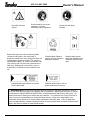
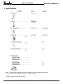
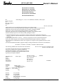
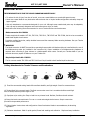
Owner’
s Man
ual
Owner’s
Manual
Model Numbers:
P/N 27344
Date 04-19-01
AST-210, AST-5000
AUT
O-ST
AR
T TRIMMERS
UTO-ST
O-STAR
ART
AST-210
Supplier To The Outdoor Power Equipment Industry
ISM, Inc. • 1028 4th Street SW • Auburn, WA 98001 • Phone: (253) 333-1200 • Fax: (253) 333-1212
www.tanakapowerequipment.com
[email protected]
AST-210,AST-5000
Owner’s Manual
Before using this unit:
•
•
•
Read the operator’s manual carefully.
Check that the cutting equipment is correctly assembled
and adjusted.
Start the unit and check the carburetor adjustment.
See “Maintenance”.
WARNING
The engine exhaust from this product
contains chemicals known to the State
of California to cause cancer, birth
defects and other reproductive harm.
Always wear eye, head and ear
protectors when using this unit.
Read, understand and follow all
warnings and instructions in this
manual and on the unit.
Keep all children, bystanders and
helpers 15m (50 ft) away from
unit. If anyone approaches you,
stop the engine and cutting
attachment immediately.
www.tanakapowerequipment.com
It is important that you read, fully understand and
observe the following safety precautions and
warnings. Careless or improper use of the unit
may cause serious or fatal injury.
Shows maximum shaft speed. Do
not use the cutting attachment
whose max rpm rating is below the
shaft rpm.
1
Do not use metal/rigid
blades when this sign is
shown on the unit.
[email protected]
AST-210,AST-5000
Be careful of thrown
objects.
Gloves should be worn when
necessary, e.g. when
assembling cutting equipment.
Blade thrust may occur when the spinning blade
contacts a solid object in the critical area. A
dangerous reaction may occur causing the entire unit
and operator to be thrust violently. This reaction is
called BLADE THRUST. As a result, the operator may
lose control of the unit which may cause serious or
fatal injury. Blade thrust is more likely to occur in
areas where it is difficult to see the material to be
cut.
Owner’s Manual
Use anti-slip and sturdy
footwear.
Contains Nickel-Cadmuim
battery. Must be recycled or
disposed of properly.
Indicates blade guard location for trimmer
head or Brain Head.
Explains choke position.
Upper sigh indicates chose
closed and the lower fully
open.
Indicates handle location. Do not
attach handle above this point.
WARNING! • Read the Operator's Manual and follow all warnings and safety instructions. Failure to
do so can result in serious injury to the operator and /or bystanders. • Objects may be thrown or ricochet
in all directions. ALWAYS WEAR EYE PROTECTION. • Keep bystanders at least 50 feet (15m) away. • To
reduce the chance of hearing loss, always wear ear protection. • To reduce the risk of injury from loss of
control, never use a metal blade on a curved shaft grass trimmer. Never use a metal blade on any
brushcutter without barrier bar or bicycle handle configuration and safety strap. • Use of a blade may
cause a sudden sideways, forward or backward motion of the brushcutter when the blade contacts a solid
object. See Owner's manual for model specific details.
www.tanakapowerequipment.com
2
[email protected]
AST-210,AST-5000
Owner’s Manual
1. What is what ?
Since this manual covers several models, there may be some difference between pictures and your unit. Use the
instructions that apply to your unit.
www.tanakapowerequipment.com
3
[email protected]
AST-210,AST-5000
Owner’s Manual
•
2. Warnings and safety instructions.
•
•
•
•
Operator Safety
•
Always wear a safety face shield or goggles.
•
Always wear heavy, long pants, boots and gloves. Do not
wear loose clothing, jewelry, short pants, sandals or go
barefoot. Secure hair so it is above shoulder length.
•
Do not operate that tool when you are tired, ill or under the
influence of alcohol, drugs or medication.
•
Never let a child or inexperienced person operate the
machine.
•
Wear hearing protection.
•
Never start or run the engine inside a closed room or
building. Breathing exhaust fumes can kill.
•
Keep handles free of oil and fuel.
•
Keep hands away from cutting equipment.
•
Do not grab or hold the unit by the cutting equipment.
•
When the unit is turned off, make sure the engine has
stopped before the unit is set down.
•
When operation is prolonged, take a break from time to time
so that you may avoid possible white finger disease, which is
caused by vibration.
•
Maintenance Safety
•
Maintain the tool according to recommended procedures.
•
Disconnect the spark plug before performing maintenance
except for carburetor adjustments.
•
Keep others away when making carburetor adjustments.
•
Use only genuine replacement parts as recommended by the
manufacturer.
Transport and storage
•
Carry the tool by hand with the engine stopped and the
muffler away from your body.
•
Allow the engine to cool, empty the fuel tank, and secure the
tool before storing or transporting in a vehicle.
•
Empty the fuel tank before storing the tool. It is
recommended that the fuel be emptied after each use.
If fuel is left in the tank, store so fuel will not leak.
•
Store tool out of the reach of children.
•
Clean the unit carefully and store it in a dry place.
•
Make sure engine switch is off when transporting or storing.
•
When transporting in a vehicle, cover blade with blade cover.
Tool Safety
•
Inspect the entire tool before each use. Replace damaged
parts. Check for fuel leaks and make sure all fasteners are in
place and securely fastened.
•
Replace parts that are cracked, chipped or damaged in any
way before using the tool.
•
Make sure the safety guard is properly attached.
•
Keep others away when making carburetor adjustments.
•
Use only accessories as recommended for this tools by the
manufacturer.
If situations occur which are not covered in this manual, take care and
use good judgment. Contact your dealer if you need assistance.
Safety Instructions for auto-start
•
Do not press the “Start Button” while recharging the battery.
If pressed, it would result in damage to the battery charger.
The batter charger must be disconnected from the unit
before starting.
•
Do not attempt to charge the battery with other than the
Tanaka charger. Do not attempt to charge other batteries
with the Tanaka charger. The charger and the battery have
specific voltage requirements and are designed to work only
if connected together.
•
The charger is designed for standard household electrical
power. Do not attempt to use any other voltage.
•
Do not expose the charger and battery to rain or snow.
•
Do not store the unit or its charger where temperatures
reach 125° F (51° C) or below 25° F (-32° C).
•
Do not short circuit or in any way alter the charging system
since it would result in damage to the battery and/or the
unit.
•
Do not store or operate near open flames since it might
cause the battery to burst and/or release toxic material.
WARNING!
Never modify the tool in any way. Do not use the tool for any job
except that for which it is intended.
Fuel Safety
•
Mix and pour fuel outdoors and where there are no sparks or
flames.
•
Use a container approved for fuel.
•
Do not smoke or allow smoking near fuel or the tool or while
using the tool.
•
Wipe up all fuel spills before starting engine.
•
Move at least 3 m (10 ft) away from fueling site before
starting engine.
•
Stop engine before removing fuel cap.
•
Empty the fuel tank before storing the tool. It is
recommended that the fuel be emptied after each use. If
fuel is left in the tank, store so fuel will not leak.
•
Store tool and fuel in area where fuel vapors cannot reach
sparks or open flames from water heaters, electric motors or
switches, furnaces, etc.
Pay special attention to statements preceded by the following words:
WARNING!
Indicates a strong possibility of severe personal injury or loss of life, if
instructions are not followed.
WARNING!
Anti-vibration systems do not guarantee that you will not
sustain white finger disease or carpal tunnel syndrome.
Therefore, continual and regular users should monitor closely
the condition of their hands and fingers. If any of the above
symptoms appear, seek medical advice immediately.
CAUTION!
Indicates a possibility of personal injury or equipment damage, if
instructions are not followed.
Cutting Safety
•
Do not cut any material other than grass and brush.
•
Inspect the area to be cut before each use. Remove objects
which can be thrown or become entangled.
•
For respiratory protection, wear an aerosol protection mask
when cutting the grass after insecticide is scattered.
www.tanakapowerequipment.com
Keep others including children, animals, bystanders and
helpers outside the 15 m (50ft) hazard zone. Stop the
engine immediately if you are approached.
Always keep the engine on the right side of your body.
Hold the tool firmly with both hands.
Keep firm footing and balance. Do not over-reach.
Keep all parts of your body away from the muffler and
cutting attachment when the engine is running.
Keep the cutting attachment below waist level.
NOTE!
Helpful information for correct function and use.
4
[email protected]
AST-210,AST-5000
Owner’s Manual
3. Assembly procedures
Drive shaft to engine (Fig.1-1)
• Apply a small amount of oil or grease to insert part of shaft tube, loosen shaft tightening bolt (1) and remove location
bolts (4).
• Insert the throttle wire (3) through the hole of the shaft grip and connect the electrical coupling (2).
• Pull flexible inner shaft out of shaft tube about 3 " and insert it into the square hole in the clutch shaft.
Insert the shaft tube into the rubber damper on the clutch case until the location hole lines up on the shaft tube (5) and
on the clutch case. If it will not go in far enough ' turn the shaft at the gear case end until the shaft tube drops into place.
*install location bolts, tighten location bolts and shaft tightening bolt.
Throttle control (Fig. 1 -1 B, 1C)
• Remove throttle trigger screw (1) and slide the throttle trigger assembly away from the shaft grip temporarily. Connect
the throttle wire in the hole of the throttle trigger.
• Locate throttle trigger in its original position by squeezing the trigger, then slide the throttle trigger assembly back
against the shaft grip then install and tighten the throttle trigger screw (1).
Drive shaft to engine (AST-210)(Fig. 1-1D)
Loosen tube locking bolt (1).
Insert the drive shaft into the clutch case of the engine properly until the marked position (2) on the drive shaft tube
meets the clutch case.
NOTE!
When it is hard to insert drive shaft up to the marked position on the drive shaft tube, turn drive shaft by the cutter
mounting end clockwise or counterclockwise. Tighten tube locking bolt lining up the hole in the shaft tube.
www.tanakapowerequipment.com
5
[email protected]
AST-210,AST-5000
Owner’s Manual
Installation of handle (Fig. 1-2, 2B)
Attach the handle to the drive shaft tube with the angle
towards the engine.
Adjust the location to the most comfortable position before
operation.
Remove the handle bracket (1) from the assembly. (Fig. 1 -3)
Place the handles and attach the handle bracket with four bolts lightly. Adjust to appropriate position. Then fix it
firmly with the bolts.
Throttle wire/stop cord (AST-210)
Connect stop cord connectors. (Fig. 1-4)
Connect throttle wire end to carburetor. (Fig. 1-5)
Installation of blade guard (Fig. 1-6, 6B, 6C)
Install the blade guard on the drive shaft tube against the gear case.
Tighten the guard bracket firmly so that the blade guard does not swing or move down during operation.
CAUTION!
Some blade guards are equipped with sharp line limiters. Be careful when handling it.
CAUTION!
Do not attempt to install metal blade on AST-5000, curved shaft trimmer. It is very dangerous.
www.tanakapowerequipment.com
6
[email protected]
AST-210,AST-5000
Owner’s Manual
When using a trimmer head (2) with two-piece type blade guard,
attach the guard extension to the blade guard. (Fig. 1-7)
Then locate the guard above the angle transmission. (Fig. 1-7B)
NOTE!
If your unit has guard location label on drive shaft tube,
follow the indication.
NOTE!
To remove the guard extension, refer to the drawings. Wear
gloves as the extension has a sharp line limiter, then push the
four square tabs on the guard one by one in order. (Fig. 1 -7C)
Other blade guards
When using a trimmer head locate the guard 20 mm (1/4 in.) or 120mm (5 in.)above the gear case.
When using a blade, mount the guard against the gear case. (Fig. 1 -8, 8B)
Installation of cutting equipment (Fig.1-9)
When installing a cutting blade, make sure that there is no cracks or any damage in it and that the cutting edges are facing the correct
direction.
NOTE!
When installing cutter holder cap (1), be sure to set concave side upward.
Insert the allen wrench (2) into the hole of the angle transmission in order to lock the cutler holder (3). Please note that the cutter
fixing bolt (4) has left handed threads, (clockwise to loosen/counter-clockwise to tighten). Tighten the fixing bolt with the box wrench.
CAUTION!
Before operation, make sure the blade has been properly installed.
CAUTION! If your unit is equipped with protection cover under a cutting blade, check it for weariness or
cracks before operation. If any damage or weariness is found, replace it, as it is an article of consumption.
Installation of the cutting head
NOTE!
For installation see your cutting head Owner's manual, provided with the cutting head.
WARNING!
For TANAKA heads or TANAKA alloy head, use only flexible, non-metallic line recommended by the manufacturer. Never use wire or
wire-ropes. They can break off and become a dangerous projectile.
NOTE! When using TANAKA alloy head (CH-100), initial cuffing line length should be about 13cm each.
(Fig. 1-10)
www.tanakapowerequipment.com
7
[email protected]
AST-210,AST-5000
Owner’s Manual
4. Operating procedures
Fuel (Fig. 2-1)
WARNING!
The trimmer is equipped with a two-stroke engine. Always run the engine on fuel, which is mixed with oil.
Provide good ventilation, when fueling or handling fuel.
Fuel
• Always use branded 89 octane unleaded gasoline.
• Use Tanaka two-cycle oil or a quality two-cycle oil at mixing ratio of 25-50:1 (Gasoline (A) : Oil (B)), only for the
state of California at 50:1.
• Never use multi-grade oil (10 W/30) or waste oil.
• Always mix fuel and oil in a separate clean container.
Always start by filling half the amount of fuel, which is to be used. Then add the whole amount of oil. Mix (shake)
the fuel mixture.
Add the remaining amount of fuel.
Mix (shake) the fuel-mix thoroughly before filling the fuel tank.
Fueling
WARNING!
•
Always shut off the engine before refueling.
•
Slowly open the fuel tank, when filling up with fuel, so that possible over-pressure disappears.
•
Tighten the fuel cap carefully, after fueling.
•
Always move the trimmer at least 3 m (10 ft.) from the fueling area before starting.
Before fueling, clean the tank cap area carefully, to ensure that no dirt falls into the tank.
Make sure that the fuel is well mixed by shaking the container, before fueling.
www.tanakapowerequipment.com
8
[email protected]
AST-210,AST-5000
Owner’s Manual
Starting (Fig. 2-2, 2B)
CAUTION!
Before starting, make sure the cutting attachment does not touch anything.
The battery is not fully charged at the factory. It is necessary to charge it fully
before operation. Please follow "Charging Procedures".
1 .Depress the priming bulb (3) several times until fuel flows through the bulb or
return pipe.
2. Depress the fuel injection button (4) once which transfers fuel from the
carburetor to the combustion chamber. (AST-250) (Fig. 2-2)
NOTE!
When the engine is warm it is not necessary to depress the priming bulb or the fuel injection button when starting. If this
is done, the engine may become flooded and hard to start.
3. Make sure throttle trigger is not locked. Do not use throttle lock (3).
4. Lift up start control lever (1) to vertical or start position. Do not push it further or the lever may break. (AST-210) (Fig.
2-2C)
5. Turn the switch to the "ON"(1) position and depress the start button (2) until the engine starts. Warm the engine by
running at idle speed for 2 to 3 minutes. (Fig. 2-2B)
CAUTION!
Do not depress the "Start Button" for more than 10 seconds continuously, as this may cause premature power drainage
of the batteries.
www.tanakapowerequipment.com
9
[email protected]
AST-210,AST-5000
Owner’s Manual
If the engine does not start:
1. If the engine starts but does not continue to run, repeat steps 1 to 5.
2. If the starter does not make any noise, repeat the charging procedures.
(Optional)(AST-250)
3. To start the unit with the recoil starter, if so equipped, follow starting procedures number 1 and turn the switch to
the "On" position then pull the recoil starter handle briskly. (Fig. 2-2D)
Stopping (Fig. 2-2B)
Decrease engine speed, set ignition switch to (OFF) position.
WARNING!
A blade can injure while it continues to spin after the engine is stopped or power control is released. When the unit is turned
off, make sure the cutting attachment has stopped before the unit is set down.
Battery charging procedure
The unit has a self-charging system, however, it may require charging if the unit is stored and the battery output becomes
low.
•
Plug the battery charger (2) into a household electrical outlet and connect the electrical coupling (3) to the coupling on
the top of the throttle lever assembly or battery coupling (4). (Fig. 2-3)
CAUTION!
•
Do not leave the charger plugged in for more than 24 hours.
•
Do not charge battery where temperatures are below 32° F(0°C) or above 113°F(45° C). If this is done the battery may
not accept a full charge.
NOTE!
When completely discharged the battery will take approximately 15 hours to charge.
www.tanakapowerequipment.com
10
[email protected]
AST-210,AST-5000
Owner’s Manual
Cutting (Fig. 2-4, 4B, 4C, 4D)
• When cutting, operate engine at over 6500 rpm. Extended use at a slow speeds may wear the clutch prematurely.
• Cut grass from right to left.
• Blade thrust may occur when the spinning blade contacts a solid object in the critical area. A dangerous reaction may
occur causing the entire unit and operator to be thrust violently. This reaction is called BLADE THRUST. As a result,
the operator may lose control of the unit which may cause serious or fatal injury. Blade thrust is more likely to occur
in areas where it is difficult to see the material to be cut.
• Wear the harness as shown in the figure (if so equipped). The blade turns counterclockwise, therefore, be advised to
operate the unit from right to left for efficient cutting. Keep onlookers out of working area at least 15 m (50 ft.).
NOTE!
Press the quick release button or pull emergency release flap (If so equipped) in the event of emergency. (Fig. 2-4C)
Stopping (Fig. 2-5)
•
Decrease engine speed and run at an idle for a few minutes, then turn off ignition switch.
WARNING!
If the cutting attachment should strike against stones or other debris, stop the engine and make sure the
attachment and related parts are undamaged. When grass or vines wrap around attachment, stop engine
and attachment and remove them.
www.tanakapowerequipment.com
11
[email protected]
AST-210,AST-5000
Owner’s Manual
5. Maintenance
MAINTENANCE, REPLACEMENT, OR REPAIR OF THE EMISSION CONTROL DEVICES AND SYSTEMS MAY BE
PERFORMED BY ANY NONROAD ENGINE REPAIR ESTABLISHMENT OR INDIVIDUAL.
Carburetor adjustment (Fig. 3-1, 1B)
WARNING!
The cutting attachment may be spinning
during carburetor adjustments.
WARNING!
Never start the engine without the complete clutch cover and tube assembled! Otherwise the clutch can come loose and
cause personal injuries.
In the carburetor, fuel is mixed with air. When the engine is test run at the factory, the carburetor is basically adjusted. A
further adjustment may be required, according to climate and altitude. The carburetor has one adjustment possibility:
T = Idle speed adjustment screw.
Idle speed adjustment (T)
Check that the air filter is clean. When the idle speed is correct, the cutting attachment will not rotate. If adjustment is
required, close (clockwise) the T-screw, with the engine running, until the cutting attachment starts to rotate.
Open (counter-clockwise) the screw until the cutting attachment stops. You have reached the correct idle speed when the
engine runs smoothly in all positions well below the rpm when the cutting attachment starts to rotate.
If the cutting attachment still rotates after idle speed adjustment, contact your service workshop.
NOTE!
Standard Idle rpm is 2500-3000 rpm.
WARNING!
When the engine is idling the cutting attachment must under no circumstances rotate.
Air filter (Fig. 3-2, 2B)
The air filter must be cleaned from dust and dirt in order to avoid:
• Carburetor malfunctions.
• Starting problems.
• Engine power reduction.
• Unnecessary wear on the engine parts.
• Abnormal fuel consumption.
Clean the air filter daily or more often if working in exceptionally dusty areas.
Cleaning the air filter
Remove the air filter cover and the filter (1).
Rinse it in warm soap suds. Check that the filter is dry before reassembly. An air filter that has been used for some time
cannot be cleaned completely. Therefore, it must regularly be replaced with a new one. A damaged filter must always be
replaced.
www.tanakapowerequipment.com
12
[email protected]
AST-210,AST-5000
Owner’s Manual
Fuel Filter (Fig. 3-2B)
Drain all fuel from fuel tank and pull fuel filter line from tank. Pull filter
element out of holder assembly and rinse element in warm water with
detergent.
Rinse thoroughly until all traces of detergent are eliminated. Squeeze,
do not wring, away excess water and allow element to air dry.
NOTE!
If element is hard due to excessive dirt buildup, replace it.
Spark plug (Fig. 3-3)
The spark plug condition is influenced by:
• An incorrect carburetor setting.
• Wrong fuel mixture (too much oil in the gasoline)
• A dirty air filter.
• Hard running conditions (such as cold weather).
These factors cause deposits on the spark plug electrodes, which may result in malfunction and starting difficulties. If the
engine is low on power, difficult to start or runs poorly at idling speed, always check the spark plug first. If the spark plug
is dirty, clean it and check the electrode gap. Readjust if necessary. The correct gap is 0.6 mm. The spark plug should be
replaced after about 100 operation hours or earlier if the electrodes are badly eroded.
NOTE! In some areas, local law requires using a resistor spark plug to suppress
ignition signals. If this machine was originally equipped with resistor spark plug, use same
type of spark plug for replacement.
Muffler (Fig. 3-4)
Remove the muffler and remove excess carbon from the exhaust port or muffler inlet every 100 hours of operation.
Cylinder (Engine cooling) (Fig. 3-4B)
The engine is air cooled, and air must circulate freely around engine and over cooling fins on cylinder head to prevent
overheating.
Every 100 Operating hours, or once a year (more often if conditions require), clean fins and external surfaces of engine of
dust, dirt and oil deposits which can contribute to improper cooling.
NOTE!
Do not operate engine with engine shroud or muffler guard removed as this will cause overheating and engine damage.
www.tanakapowerequipment.com
13
[email protected]
AST-210,AST-5000
Owner’s Manual
Flexible drive shaft (Fig. 3-5)
Flexible drive shaft should be removed and lubricated
with a good quality lithium grease every 20 hours. To
remove the flexible shaft, first remove screw (1), loosen
bolt (2) and remove the gear case then pull the shaft out
of the drive shaft pipe. Clean the shaft off and apply a
generous coat of lithium grease to it and insert if back
into the drive shaft pipe, turn it until it drops into place
then install the gear case, and install & tighten screw (1)
and screw (2).
Angle transmission (Fig. 3-5B)
Check angle transmission or angle gear for grease level about every 50 hours of operation by removing the grease filler plug
on the side of angle transmission.
If no grease can be seen on the flanks of the gears, fill the transmission with a quality lithium based multipurpose grease up
to ¾ full. Do not completely fill the transmission.
Blade (Fig. 3-6)
WARNING!
Wear protective gloves when handling or performing
maintenance on the blade.
•
Use a sharp blade. A dull blade is more likely to snag and thrust. Replace the fastening nut if it is damaged and hard
to tighten.
•
When replacing blade, purchase one recommended by TANAKA, with a 25.4mm (one inch) mounting hole.
•
When installing a saw blade (2), always face the stamped side up. In the case of a 4 tooth blade (1), it can be used
on either side.
•
Use correct blade for the type of work.
•
When replacing a blade, use appropriate tools.
•
When cutting edges become dull, re-sharpen or file as shown in figure. Incorrect sharpening may cause excessive
vibration.
•
Discard blades that are bent, warped, cracked, broken or damaged in any way.
NOTE!
When sharpening blade it is important to maintain an original shape of radius at the base of the tooth to avoid cracking.
www.tanakapowerequipment.com
14
[email protected]
AST-210,AST-5000
Owner’s Manual
Battery Removal (AST-5000)
1.Separate drive shaft from engine and throttle wire (1) from throttle trigger. Disconnect couplers (2).
(Fig. 3-7)
2. Remove four screws (4), which are retaining fan case cover (3). (Fig. 3-8)
3. Bind the female coupler with long nose pliers and push it to separate the coupler from fan case cover (3).
(Fig. 3-9)
4. After removing the fan case cover, pull out the battery with the waterproof cover (1). (Fig. 3-10)
5. Disconnect battery couplers (2), pull out circuit plate (3) and then, separate the battery (4) with the
waterproof cover from the engine main unit. (Fig. 3-11)
6. Remove vinyl tape (6) which fixes battery (5) on the waterproof cover (1), then push out the battery from the
cover (1). (Fig. 3-12)
www.tanakapowerequipment.com
15
[email protected]
AST-210,AST-5000
Owner’s Manual
Maintenance schedule
Below you will find some general maintenance instructions.
For further information please contact your Tanaka service dealer.
Daily maintenance
•
Clean the exterior of the unit.
•
Check that the harness is undamaged.
•
Check the blade guard for damage or cracks. Change the guard in case of impacts or cracks.
•
Make sure the cutting attachment is properly centered, sharp, and without cracks. An off-centered
cutting attachment induces heavy vibrations that may damage the unit.
•
Make sure the cutting attachment nut is sufficiently tightened.
•
Make sure that the blade transport guard is undamaged and that it can be securely fitted.
•
Make sure fasteners are tightened.
Weekly maintenance
•
Check the starter, especially cord and return spring.
•
Clean the exterior of the spark plug.
•
Remove it and check the electrode gap. Adjust it to 0.6 mm, or change the spark plug.
•
Clean the cooling fins on the cylinder and check that the air intake at the starter is not clogged.
•
Make sure the gear case is filled with grease up to ¾ full.
•
Clean the air filter.
Monthly maintenance
•
Rinse the fuel tank with gasoline.
•
Clean the exterior of the carburetor and the space around it.
•
Clean the fan and the space around it.
www.tanakapowerequipment.com
16
[email protected]
AST-210,AST-5000
Owner’s Manual
6. Optional
Installation of free disk set (optional) (Fig. 4-1, 1 B)
1) Disassemble free disk (7) from the free disk set by loosening three bolts (8).
2) Place blade (3) as shown in drawing. Disk fixing bolt (4) is left-hand threaded ' Use special care to fix blade firmly. Use
alien wrench (1) to hold cutter holder (2) so that you may easily tighten up disk fixing bolt (4) with wrench (6).
3) Make sure cutting blade is fixed securely, attach free disk (7) to disk fixing metal (5) with three bolts (8).
Spark arrestor
If your unit comes with a spark arrestor screen and your local regulation requires use of spark arrestor screens for fire
prevention, please attach it to the muffler by removing muffler protector and other related parts.
(The spark arrestor meets the regulation of SAE J335-SEP90 and CSA CAN3-Z62. 1 -M77)
www.tanakapowerequipment.com
17
[email protected]
AST-210,AST-5000
Owner’s Manual
7. Specifications
Note : Sound levels are calculated as the time-weighted energy total under various working
conditions with the following time distribution : ½ idling, ½ racing.
* All data subject to change without notice.
www.tanakapowerequipment.com
18
[email protected]
AST-210,AST-5000
Owner’s Manual
Declaration of conformity
D6claration de conformit6
Dichiarazione di conformita
Konformitiitserkliirung
Declaraci6n de conformidad
Konformitetsdeklaration
We,
Nous,soussignds,
Noi,
Der unterzelchnete,
Nosotros,
Tanaka Kogyo Co., Ltd., 3-4-29 Tsudanuma, Narashino, Chiba, Japan
vi,
AST-210, AST-5000
Declare under our sole responsibility that the product, grass trimmer model
D6clarons sous notre scule responsabilit6 que le-produit en question, tondeuse de gazon mod~le
Dichiariamo sotto la nostra unica responsabilita che il prodotto, il bordatore modello
Erklart unter, eigener Verantwortung, daB das Produkt, rasenmaher modell
Declaramos dajo nuestra 6nica responsabilidad que el producto, corta-cespedes modelo
F6rklarar harmed pd eget ansvar att denna produkt, grsaklippare modell
to which this declaration relates is in conformity with the essential safety requirements of directives.
laquelle se rapporte la pr6sente ddclaration est conforme aux directives concernant les conditions de s6curit6
essentielles.
al quale questa dichiarazione si riferisce, ~ conforme ai requisiti di sicurezza essenziali delle direttive.
fijr das these Erklar-ung gilt, den wesentlichen Sicherheitsanforderungen der Directive entspricht.
que corresponde a esta declaracl6n, satisface la (s) siguiente (s) exigencia (s) de seguridad esencial (es) de las
directivas.
till vilken denna deklaration tillh6r, uppfyller samtliga vasentilga sakerhetskrav f6reskrivna i ber6rda direktiv.
89/392/EEC, 91/368/EEC, 93/44/EEC, 93/68/EEC, EMC89/336/EEC
The following standards have been taken into consideration
Les normes suivantes ont 6t6 prises en consid6ration. Sono
stati presi in considerazione i seguenti standard. Die
nachfolgenden Standards wurden in Betracht gezogen. Se
han tenido en consideraci6n las siguientes normas. Vi har
tagit hansyn till f6ljande standards.
Manufactured at:
Fait A:
Luogo:
Erstellt in:
Fabricado en:
Tillverkad av:
Chiba, Japan
ISO 7112/7113/7916/7917/7918/8380/11682
(EN-292-2, EN ISO 11806)
Serial No. up from
No. de s6ric A partir de
Num. di serie da
Scrien-Nr. ab
No. de Serie de
Serienr fr.o.m.
v001001
en adelante
Signature:
Signature:
Firma:
Unterschrift:
Fimado:
Signatur:
Position:
Function:
Incarico:
Titel:
Cargo:
Befattning:
Vice president
Vice-pr6sident
Vicepresidente
Stellvertretender Vorsitzender
Vicepresidente
Vice President
www.tanakapowerequipment.com
19
[email protected]
AST-210,AST-5000
Owner’s Manual
IMPORTANT NOTICE
THIS INFORMATION IS FOR THE US AND CANADIAN MARKETS ONLY.
• To reduce the risk of injury from loss of control, never use a metal blade on a curved shaft grass trimmer.
• Never use a metal blade on any brushcutter without barrier bar or bicycle handle configuration and safety strap and
approve guard.
• Use only attachments or accessories designed for your unit. Although some unauthorized parts may be adaptable,
their use may be extremely dangerous and could cause serious injury or death.
Tanaka offers the following kits and accessories for use on Tanaka trimmers and brushcutters.
Blade conversion Kit #748501
Tanaka straight shaft models: AST-210, TBC-2211, TBC-2510 , TBC-270PF and TBC-270PN, this kit to be converted to
metal blade-capable brush cutters.
It contains a safety barrier bar, safety shoulder harness and the necessary blade mounting hardware. See your Tanaka
dealer for more details.
WARNING!
The blade conversion kit MUST be used when operating these models with blades and do not install without the use of
the blade-securing cotter pin (included in the conversion kit). Proper installation of all blade-mounting hardware is
required when converting a grass trimmer to a blade-capable brush cutter. Consult your Tanaka dealer if you are
uncertain about any aspect of blade use on your Tanaka unit.
Bicycle Style Handle Kit #748502
This kit converts models TBC-2510 and TBC-3010 from D style handle to dual handled style brushcutters.
Cutting Attachments for Tanaka Trimmers and Brushcutters
(1) Fixed line commercial cutting heads offer excellent durability and light weight. Great for commercial use.
(2) Tanaka Brain fully automatic heads. The Brain senses when more line is needed and utilizes centrifugal
force to always feed the perfect length of line.
(3) Copolymer nylon cutting line. Easy to load into any trimmer head. Resilient, flexible and melt resistant.
(4) Bump feed semi-automatic heads. For use on curved and straight shaft trimmers. Simple construction
provides for dependable performance.
(5) Cutting blades. Various sizes and configuration of steel brushcutter blades to accomodate any brushcutting
application.
(6) Cultivator attachment. Ideal for quick garden/ flower bed weeding and cultivation. Simple and easy installation.
www.tanakapowerequipment.com
20
[email protected]