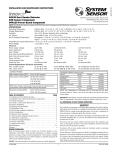
1
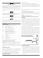
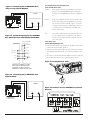
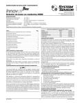
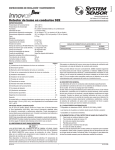
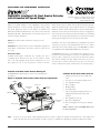
INSTALLATION AND MAINTENANCE INSTRUCTIONS
DH200RPL Intelligent Air Duct Smoke Detector
with Extended Air Speed Range
3825 Ohio Avenue, St. Charles, Illinois 60174
800/736-7672, FAX: 630-377-6495
www.systemsensor.com
Before installing detectors, please thoroughly read the NEMA Guide for
The DH200RPL air duct smoke detector is photoelectric detector. This
Proper Use of Smoke Detectors in Duct Applications, which provides
smoke detection method combines with an efficient housing design that
detailed information on detector spacing, placement, zoning, wiring,
samples air passing through a duct and allows detection of a developing
and special applications. Copies of this manual are available from
hazardous condition. When sufficient smoke is sensed, an alarm signal is
NEMA (National Electrical Manufacturers Association, 2101 L Street NW,
initiated at the fire control panel monitoring the detector, and appropriate
Washington, DC 20037). NFPA Standards 72 and 90A should also be ref-
action can be taken to shut off fans, blowers and change over air handling
erenced for detailed information.
systems, etc. This can prevent the distribution or it can isolate toxic smoke
and fire gases throughout the areas served by the duct system.
NOTICE: This manual shall be left with the owner/user of this
equipment.
Two LEDs on each detector may illuminate, if programmed by the system
control panel, to provide a local alarm indication. There is also a remote
IMPORTANT: This detector must be tested and maintained regularly fol-
alarm output for use with auxiliary devices. The DH200RPL has remote
lowing NFPA 72 requirements. The detector should be cleaned at least
test capability with the RTS451/RTS451KEY Remote Test Station.
once a year.
General Description
The DH200RPL incorporates a cover tamper feature. When the cover is
An HVAC system supplies conditioned air to virtually every area of
removed for more than 20 minutes, the unit loses communication at the
a building. Smoke introduced into this air duct system is distrib-
panel, a trouble is indicated at the panel and the alarm relay switches
uted to the entire building. Smoke detectors designed for use in air
states thereby shutting down fans, dampers and blowers. In the case
duct systems are used to sense the presence of smoke in the duct.
when the sensor is removed or when there is no power to the unit, only a
trouble is indicated at the panel (alarm relay does not work any longer).
Contents of the Duct Smoke Detector Housing Kit
The DH200RPL Duct Smoke Detector consists of the following items
Contents Of The Duct Smoke Detector
(See Figure 1.):
1.
sensor
Figure 1. Exploded View Of Duct Smoke Detector Components:
FOAM
GASKETS
CONDUIT HOLES
SAMPLING TUBE
FILTERS
SAMPLING TUBE
DETECTOR
HOUSING
2.
Two #10 x 11⁄4″ sheet metal mounting screws
3.
Two sampling tube filters
4.
One test magnet
5.
Drilling template
6.
Two foam gaskets
7.
Four #6-self tapping mounting screws for the
sampling tube and optional exhaust tube
TERMINAL STRIP
POWER BOARD
COVER MOUNTING
SCREWS
DETECTOR BOARD
Complete duct smoke detector assembly with
extension
8.
One sampling tube end cap
9.
One plastic sampling tube
10. One #8 self-tapping screw for plastic sampling
tube
NOTE: A detector sensor board DOES NOT need to
be ordered separately.
DETECTOR
COVER
NOTE:
For ducts over 11⁄2 feet (0.46m), longer sampling tubes must be ordered to complete the installation. They must be the correct length for the
width of the duct where they will be installed. See Table 1 on page 3 to determine the sampling tube required for different duct widths.
D200-39-00
1
I56-1977-004R
1. Remove the front cover.
WARNING
2. Slide the plastic sampling tube into the housing bushing.
Limitations of Duct Detectors
3. Align the holes in the bushing with the holes in the sampling tube. Make
The National Fire Protection Association has established that DUCT
sure there are 6 exposed holes on the plastic sampling tube. Secure with the
DETECTORS MUST NOT BE USED AS A SUBSTITUTE FOR OPEN AREA
#8 self-tapping screw into the bottom of the permanent tube (shown in Fig.
DETECTOR PROTECTION as a means of providing life safety. Nor are they
2).
a substitute for early warning in a building’s regular fire detection system.
NOTE:
It is strongly recommended that the user read NFPA Standards 90A, 72,
For ducts greater than 11⁄2 feet (0.46m) in width, refer to sec-
tions [4], [4.1] and [4.2].
and 101.
[3] Secure The Detector Housing To The Duct
WARNING
Slide the foam gaskets over the tube bushings as shown in Figure 3. Use
This device will not operate without electrical power. Fire situations
the two 1 1⁄4″ long sheet metal screws to screw the detector housing to
may cause an interruption of power. The system safeguards should be
the duct.
discussed with your local fire protection specialist.
CAUTION: Do not overtighten the screws.
WARNING
[4] Sampling Tube Installation for Ducts Greater Than 11⁄2 Feet
This device will not sense smoke unless the ventilation system is operat-
(0.46m) Wide
ing.
The sampling tube is identified by a series of air inlet holes on the tube.
WARNING
A plastic tube is included for ducts up to 11⁄2 feet (0.46m) wide. All other
In order to function properly, this detector must be installed according to
lengths must be purchased separately. Order the correct length, as speci-
the instructions. Do not exceed the electrical or ambient specifications or
fied in Table 1, for width of the duct where it will be installed. It is recom-
the detector will not function properly. This detector must be protected
mended that the sampling tube length extend at least 2⁄3 across the duct
from the elements.
width for optimal performance. The exhaust tube is molded onto the base
Installation Sequence
of the duct housing, and the A2440-00 Exhaust Tube Extension is available
Step 1.
Verify duct air flow direction and velocity ...........................2
as an accessory in those cases where the molded exhaust port does not
Step 2.
Drill the mounting holes.....................................................2
extend at least 2 inches (50mm) into the duct.
Step 2.1
Install the sampling tube for ducts
The sampling tube is always installed with the air inlet holes facing into
less than 11⁄2 feet (0.46m) wide ...........................................2
Step 3.
Secure the detector housing to the duct...............................2
Step 4.
Install the sampling tube for ducts
the air flow. To assist proper installation, the tube’s mounting flange is
marked with an arrow. Make sure the sampling tube is mounted so that
the arrow points into the air flow (see Figure 4). Figure 5 shows the
greater than 11⁄2 feet (0.46m) wide ......................................2
Step 4.1
various combinations of tube mounting configurations with respect to air
Installation for ducts greater than 11⁄2 feet
flow. Mounting the detector housing in a vertical orientation is acceptable,
(0.46m) but less than 8 feet (2.4m) wide ............................3
Step 4.2
provided that a metal sampling tube is installed and the air flows directly
Installation for ducts more than 8 feet
into the sampling tube holes as indicated in Figure 4.
(2.4m) wide.......................................................................4
Step 5.
Install the filters .................................................................4
Step 6.
Field wiring .......................................................................4
Step 7.
Perform detector check.......................................................5
Step 8.
Install the cover .................................................................5
Step 9.
Detector Maintenance and Test Procedures ..........................5
Figure 2. Plastic sampling tube
connected to duct smoke detector:
[1] Verify Duct Air Flow Direction And Velocity
The DH200RPL duct smoke detector is designed to be used in air handling systems having air velocities of 100 to 4000 feet per minute (0.5 to
20.32m/s). Be sure to check engineering specifications to ensure that the
air velocity in the duct falls within these parameters. If necessary, use a
[4.1] Installation For Ducts Greater Than 11⁄2 Feet (0.46m) But
velocity meter to check the air velocity in the duct. See Air Flow Test,
Less Than 8 Feet (2.4m) Wide
section 9.1.
1. If the tube is longer than the width of the air duct, drill a 3⁄4″ (19mm)
hole in the duct opposite the hole already cut for the sampling tube.
[2] Drill The Mounting Holes
template
Make sure the hole is 1″ to 2″ (25 to 50mm) below the inlet hole on
supplied. Affix the template to the duct at the desired mounting location.
the opposite side of the duct to allow moisture drainage away from the
Make sure the template lies flat and smooth on the duct. Center punch
detector. If the tube is shorter than the width of the air duct, install the
holes A and B. Drill the holes as indicated on the template.
end cap into the sampling tube as shown in Figure 4. Sampling tubes
Remove
the
paper
backing
from
the
mounting
over 3 ft. (0.91m) long must be supported at the end opposite the duct
[2.1] Sampling Tube Installation for Ducts Less Than 11⁄2 Feet
smoke detector.
(0.46m) Wide (see Figure 2)
D200-39-00
2
I56-1977-004R
Figure 5. Tube mounting configurations with varying
air flow direction:
2. Slide the tube into the housing bushing that meets the air flow first.
Position the tube so that the arrow points into the air flow, as shown
in Figure 4.
DOTS INDICATE POSITION OF
SAMPLING TUBE HOLES
3. Secure the tube flange to the housing bushing with two #6 self-tapping
AIR FLOW
DIRECTION
AIR FLOW
DIRECTION
screws.
DETECTOR
HOUSING
DETECTOR
HOUSING
4. For tubes longer than the width of the air duct, the tube should extend
out of the opposite side of the duct. If there are more than 2 holes in
the section of the tube extending out of the duct, select a different
B.
A.
SAMPLING
TUBE
length using Table 1. Otherwise, trim the end of the tube protruding
through the duct so that 1″ to 2″ (25 to 50mm) of the tube extend
EXHAUST
TUBE
EXHAUST
TUBE
SAMPLING
TUBE
HORIZONTAL MOUNTING OF HOUSING
outside the duct. Plug this end with the end cap and tape closed any
holes in the protruding section of the tube. Be sure to seal the duct
DETECTOR
HOUSING
where the tube protrudes.
EXHAUST
TUBE
AIR FLOW
DIRECTION
NOTE: The sampling tube end cap is critical to the proper operation of the
SAMPLING
TUBE
DETECTOR
HOUSING
duct smoke detectors. The end cap is needed to create the proper air flow
to the sensor of the duct smoke detector.
AIR FLOW
DIRECTION
D.
C.
VERTICAL MOUNTING OF HOUSING
NOTE: Only metal sampling tubes can be installed in
orientations C and D.
Figure 3. Installation of foam gaskets over
sampling tube bushings:
SCREW HOLES FOR
ATTACHING HOUSING
TO DUCT WORK.
[4.2] Installation For Ducts More Than 8 Feet (2.4m) Wide
NOTE:
To install sampling tubes in ducts more than 8 feet (2.4m) wide,
work must be performed inside the air duct. Sampling of air in
ducts wider than 8 feet (2.4m) is accomplished by using the
ST-10 sampling tube. If the tube is shorter than the width of the
air duct, install the end cap into the sampling tube as shown
in Figure 4 and support the end opposite the duct smoke detector.
Install the sampling tube as follows:
1. Drill a 3⁄4-inch (19mm) hole in the duct directly opposite the hole
Table 1. Sampling tubes recommended for different
duct widths:
Outside Duct Width
already drilled for the sampling tube. Make sure the hole is 1″ to 2″
(25 to 50mm) below the inlet hole on the opposite side of the duct to
Sampling Tube Recommended*
allow for moisture drainage.
1 to 2 ft. (0.3 to 0.6 m)
ST-1.5
2 to 4 ft. (0.6 to 1.2 m)
ST-3
2. Slide the sampling tube with the flange into the housing bushing that
4 to 8 ft. (1.2 to 2.4 m)
ST-5
meets the air flow first. Position the tube so that the arrow points into
8 to 12 ft. (2.4 to 3.7 m)
ST-10
the air flow. Secure the tube flange to the housing bushing with two
#6 self-tapping screws.
*Must extend a minimum of 2⁄3 the duct width
3. From inside the duct, couple the other sections of the sampling tube
to the section already installed using the 1⁄2-inch conduit fittings sup-
Figure 4. Air duct detector sampling tube:
FLANGE
AIR HOLES
plied. Make sure that the holes on both of the sampling tubes are lined
up and facing into the air flow.
SAMPLING
TUBE
END CAP
4. Trim the end of the tube protruding through the duct so that 1″ to 2″
(25 to 50mm) of the tube extend outside the duct. Plug this end with
the end cap and tape closed any holes in the protruding section of the
tube. Be sure to seal the duct where the tube protrudes.
ARROW
MUST FACE
INTO AIR FLOW
NOTE:
AIR FLOW DIRECTION
An alternate method to using the ST-10 is to use two ST-5 sampling tubes. Remove the flange from one of the tubes and install
H0108-02
as described above. After the installation, use electrical tape to
close off some of the sampling holes so that there are a total of
10 to 12 holes spaced as evenly as possible across the width of
the duct.
D200-39-00
3
I56-1977-004R
NOTE:
Air currents inside the duct may cause excessive vibration,
Two LEDs on each duct smoke detector may light, if programmed by the
especially when the longer sampling tubes are used. In these
system control panel, to provide a local, visible indication. Remote LED
cases a 3 inch (75mm) floor flange (available at most plumb-
annunciator capability is available as an option. Each duct smoke detector
ing supply stores) may be used to fasten the sampling tube to
can only be wired to one remote accessory.
the other side of the duct. When using the flange/connector
mounting technique, drill a 1-inch to 11⁄4-inch (25 to 32mm)
Different panel manufacturers offer different feature sets across their dif-
hole where the flange will be used.
ferent panel models. As a result, certain features of the DH200RPL may be
available on some control panels, but not on others. The possible features
[5] Install The Filters
To install the sampling tube filters, simply push the filters into the sam-
available in the DH200RPL, if supported by the control panel are:
pling and exhaust tube holes, as shown in Figure 6. If a metal sampling
1. Panel controls the LED operation on sensor. Operational modes are
tube is used, install the filters into the tube end.
RED blink, RED continuous, and off.
2. The remote output of the RA400Z does not follow the condition of the
CAUTION
duct smoke detector LED while in standby. When in alarm, the LED
Filters require periodic cleaning or replacement, depending on the amount
output of the detector and remote will be identical.
of dust and dirt accumulated. Visually inspect the filters at least quarterly;
Please refer to the operation manual for the UL
inspect them more often if the dust accumulation warrants it. See Section
listed control panel for specific operation of the DH200RPL.
[9.1.2] for more information. Replacement filters can be ordered (filter
P/N F36-09-11).
Wiring Instructions
Disconnect power from the communication line before installing the
Figure 6. Sampling tube filter installation:
DH200RPL duct smoke detector.
Wire the DH200RPL duct smoke detector per the Control Panel Installation
Manual and Figures 9, 10 or 11.
Set the desired address on the sensor board address code wheel switches
(see Figure 7).
[6] Field Wiring Installation Guidelines
All wiring must be installed in compliance with the National Electrical
Figure 7. Rotary Address Switches
Code and the local codes having jurisdiction. Proper wire gauges should
be used. The conductors used to connect smoke detectors to control
[7] Perform Detector Check
panels and accessory devices should be color-coded to prevent wiring
1. Perform STANDBY AND TROUBLE TEST per Section [9.2.1].
mistakes. Improper connections can prevent a system from responding
2. Perform MAGNET TEST per Section [9.2.2.1]. The
properly in the event of a fire.
RTS451 test of Section [9.2.2.2] may substitute for this requirement.
For signal wiring, (the wiring between detectors or from detectors to auxil-
3. Perform AIR FLOW TEST per Section [9.1].
iary devices), it is usually recommended that single conductor wire be no
4. Perform SMOKE RESPONSE TEST per Section [9.1.1].
smaller than 18 gauge. The duct smoke detector terminals accommodate
[8] Install The Cover
wire sizes up to 12 gauge. The last foot (0.3m) of conduit should be flex-
Install the cover using the six screws that are captured in the housing
ible conduit (available in electrical supply houses), which facilitates easier
cover. Be certain filters are installed as specified in Section [5]. Make sure
installation and puts less strain on the conduit holes in the housing. Solid
that the cover fits into the base groove and that all gaskets are in their
conduit connections may be used if desired.
proper positions. Tighten the six screws.
Smoke detectors and alarm system control panels have specifications for
[9] Duct Smoke Detector Maintenance and Test Procedures
Signaling-Line Circuit (SLC) wiring. Consult the control panel manufactur-
Test and maintain duct smoke detectors as recommended in NFPA 72. The
er’s specifications for wiring requirements for the particular model control
tests contained in this manual were devised to assist maintenance person-
panel being used before wiring the detector loop.
nel in verification of proper detector operation.
The DH200RPL detector is designed for ease of wiring. The housing
Before conducting these tests, notify the proper authorities that the smoke
provides a terminal strip with clamping plates. Wiring connections are
detection system will be temporarily out of service. Disable the device or
made by stripping about 3⁄8-inch (9mm) of insulation from the end of the
system under test to prevent unwanted alarms.
wire, sliding the bare end under the plate, and tightening the clamping
plate screw.
D200-39-00
4
I56-1977-004R
[9.1] Smoke Entry Tests
[9.1.1] Air Flow
[9.1.4] Air Flow Test using Dwyer Series 607 Differential Pressure
Transmitter
This product is designed to operate over an extended air speed range of 100
Verify the air speed of the duct using an anemometer. Air speed must be at
to 4000 FPM. To verify sufficient sampling of ducted air, turn the air han-
least 100 FPM. Wire the Dwyer transmitter as shown in Figure 8. Connect
dler on and use a manometer to measure the differential pressure between
the leads of the meter to either side of the 1000Ω resistor. Allow unit to
the two sampling tubes. The differential pressure should measure at least
warm up for 15 seconds. With both HIGH and LOW pressure ports open
0.0015 inches of water and no more than 1.2 inches of water. Because most
to ambient air, measure and record the voltage drop across the 1000Ω
commercially available manometers cannot accurately measure very low
resistor (measurement 1), 4.00 volts is typical. Using flexible tubing and
pressure differentials, applications with less than 500 FPM of duct air speed
rubber stoppers, connect the HIGH side of the transmitter to the sampling
may require one of the following: 1) the use of a current-sourcing pressure
tube of the duct smoke detector housing, and the LOW side of the trans-
transmitter (Dwyer Series 607) per Section 9.1.4 or; 2) the use of aerosol
mitter to the exhaust tube of the duct smoke detector housing. Measure
smoke per section 9.1.2.
and record the voltage drop across the 1000Ω resistor (measurement 2).
Subtract the voltage recorded in measurement 1 from the voltage recorded
[9.1.2] Air Flow Test using Aerosol Smoke
in measurement 2. If the difference is greater than 0.15 volts, there is
This test is intended for low-flow systems (100-500 FPM). If the air speed
enough air flow through the duct smoke detector for proper operation.
is greater than 500 FPM, use a conventional manometer to measure differ-
Figure 8. Procedure for verifying air flow:
ential pressure between the sampling tubes, as described in 9.1.1.
TO SAMPLING TUBE
Drill a 1⁄4″ hole 3 feet upstream from the duct smoke detector. With the
TO EXHAUST TUBE
air handler on, measure the air velocity with an anemometer. Air speed
must be at least 100 FPM. Spray aerosol smoke* into the duct through the
HIGH
1
⁄4″ hole for five seconds. Wait two minutes for the duct smoke detector
LOW
DIFFERENTIAL
PRESSURE
TRANSMITTER
MODEL #607-01
to alarm. If the duct smoke detector alarms, air is flowing through the
detector. Remove the duct smoke detector cover and blow out the residual
15 TO 36VDC
SUPPLY
aerosol smoke from the chamber and reset the duct smoke detector. Use
9 VOLT
BATTERY
duct tape to seal the aerosol smoke entry hole.
1000 OHM 5% 1 WATT RESISTOR
9 VOLT
BATTERY
9 VOLT
BATTERY
*Aerosol smoke can be purchased from Home Safeguard Industries,
Malibu, CA. Phone: 310/457-5813.
VOLT METER
FLUKE MODEL 87
OR EQUIVALENT
[9.1.3] Smoke Entry Test
To determine if smoke is capable of entering the sensing chamber, visually
identify any obstructions. Plug the exhaust and sampling tube holes to
prevent ducted air from carrying smoke away from the detector head, then
blow smoke such as cigarette, cotton wick, or punk directly at the head to
cause an alarm. REMEMBER TO REMOVE THE PLUGS AFTER THIS TEST,
OR THE DETECTOR WILL NOT FUNCTION PROPERLY.
H0163-01
[9.1.5] Filter Replacement
The filters do not substantially affect smoke performance even when up
to 90% of the filter is clogged. Quarterly visual inspection usually suffices to determine whether the filters should be replaced because only a
high percentage of contamination affects performance. If further testing
is required, compare differential pressure readings with and without the
filters installed. If the difference exceeds 10% replace the filters. In no case
should the pressure differential fall below 0.0015 inches of water.
1
2
COM (-)
COM (+)
COM (-)
+
COM (+)
Figure 9. Wiring Diagram for DH200RPL Duct Smoke Detector using a UL listed control panel:
NOTE: Jumper J1 shunt must be installed for 2-W applications. J1 shunt must be removed for power PCB supervision.
NOTE: J1 JUMPER MUST
BE INSTALLED FOR 2W
APPLICATIONS. THE
J1 JUMPER MUST BE
REMOVED FOR POWER
BOARD SUPERVISION.
1 2
COMMUNICATION
LINE
–
UL LISTED CONTROL
PANEL
D200-39-00
J1 JUMPER
1ST DETECTOR
IN LOOP
J1 JUMPER
5
2ND DETECTOR
IN LOOP
I56-1977-004R
Figure 10. Wiring Diagram for DH200RPL Duct
Detector with optional RA400Z:
[9.2] Standby, Alarm, And Sensitivity Tests
[9.2.1] Standby And Trouble
Standby —
If the system control panel is programmed, look for the
presence of the flashing LEDs through the transparent
housing cover. The LED will flash with each communicat-
RA400Z
5 7
ion.
DO NOT BREAK TAB ON RA400Z
Trouble —
If the detector LEDs do not flash, then the de-tector lacks
power (check wiring, panel pro-gramming, or power sup
ply), the detector board is missing (replace), or the unit
is defec-tive (return for repair). Additionally, if the cover
5 = Alarm Signal
7 = Aux. Power (–)
is removed for more than 20 minutes, the LEDs of the
detector will not flash.
Test —
fy correct operation of the system. Remove the detector
Figure 11. System Wiring Diagram for DH200RPL
Duct Smoke Detector with RTS451/RTS451KEY:
board to cause a trouble condition locally and at the system control panel.
[9.2.2] Alarm Tests
RTS 451/RTS451KEY
[9.2.2.1] M02-04-00 Magnet Test
1
ALARM SIGNAL
1. Place the painted surface of the magnet onto the TEST locator on the
3
NOT USED
5
6
7
2
4
4
3
5
ALARM SIGNAL
bottom of the detector housing (Figure 13).
2. Verify system control panel alarm status and control panel execution
NOT USED
AUX. POWER (–)
of all intended auxiliary functions (i.e. fan shutdown, damper control,
CIRCUIT
REFERENCE
etc.)
3. The detector is self-restoring when the magnet is removed. Verify that
TEST +
TEST –
The trouble condition can be caused intentionally to veri-
TEST
SWITCH
the system control panel has reset; panel may have to be reset.
Figure 13. Testing detector alarm:
FOR RTS451, TERMINAL 3 IS NOT
USED. (RTS451 DOES NOT HAVE
A TERMINAL 6.) FOR RTS451KEY,
TERMINALS 3 AND 6 ARE NOT USED.
Figure 12. Wiring Diagram for DH200RPL with
optional PA400:
5 7
PA400
Figure 14. Insulator Card for DH200RPL Duct Smoke
Detector:
5 = Alarm Signal
7 = Aux. Power (–)
D200-39-00
6
I56-1977-004R
[9.2.2.2] RTS451/RTS451KEY Remote Station Test
[10] Board Replacement
The RTS451/RTS451KEY Remote Test Station facilitates test of the alarm
[10.1] Sensor Board Replacement
capability of the duct smoke detector.
1. Remove the two sensor board mounting screws.
These accessories provide the
stimulus to initiate an alarm condition at the detector. The detector is
2. Pull gently on the board to remove it.
self-restoring when the accessory test stimulus is removed. Verify that the
3. To replace the board, align the board mounting features, holes, and the
interconnect terminals. Push the board into place.
system control panel has reset; panel may need to be reset.
4. Secure board with the two mounting screws.
[9.2.3] Sensitivity Tests
Notify the proper authorities that the smoke detector system is undergo-
[10.2] Power Board Replacement
ing maintenance, and that the system will temporarily be out of service.
1. Disconnect wiring from the terminal block.
Disable the device or system undergoing maintenance to prevent unwant-
2. Remove the two power board mounting screws.
ed alarms and possible dispatch of the fire department.
3. Pull gently on the board to remove it.
4. To replace the board, align the board mounting features, holes, and the
interconnect terminals. Push the board into place.
[9.3] Maintenance of Duct Smoke Detectors [9.3.1] Air Filters
1. Turn off power to the system.
5. Secure board with the two mounting screws.
2. Remove and inspect sampling tube filters.
6. Re-connect wiring to terminal block.
3. If filters are heavily coated with dirt, replace them with new filters
(p/n F36-09-11). If they are not heavily coated, use a vacuum cleaner
[11] Model DH200RPL Air Duct Smoke Detector Specifications
or compressed air nozzle to remove dust, then reinstall the filters.
Operating Temperature Range 32° to 131°F (0° to 55°C)
[9.3.2] Photo Detector Boards
Storage Temperature Range
-22º to 158ºF (-30º to 70ºC)
1. Remove the screen by gently grasping on each side and pulling straight
Humidity Range
10% to 93% (non-condensing)
Air Velocity
100 to 4000 ft/min (0.5 to 20.32 m/sec.)
Dimensions
143⁄8″ L x 51⁄2″ W x 23⁄4″ D (37 cm L x
off
2. Lift the photo chamber in the same fashion. Vacuum the screen and
14 cm W x 7 cm D)
cover. Use clean, compressed air to loosen and blow out any remaining
debris. Replacement screens (p/n S08-39-01) are available.
3. Vacuum photo chamber, then use clean compressed air to blow area
clean.
4. Replace the chamber by pressing it onto the base. Press the screen into
place. It should fit tightly on the chamber.
D200-39-00
7
I56-1977-004R
Current Requirements (using no accessories)
Power supply voltage:
Max. standby current:
Max. alarm current:
Alarm response time:
Power up time:
20-30 VDC
24 VAC, 50-60 Hz
120 VAC, 50-60Hz
220/240 VAC, 50-60Hz
26 mA
65 mA RMS
44 mA RMS
25 mA RMS
87 mA
182 mA RMS
52 mA RMS
30 mA RMS
3 to 10 Sec.
3 to 10 Sec.
3 to 10 Sec.
3 to 10 Sec.
2 Sec.
2 Sec.
2 Sec.
2 Sec.
Contact Ratings
Accessory Current Loads at 24 VDC
Alarm auxiliary contacts* (DPDT)
10 A @ 30 VDC
Device
Standby
Alarm
10 A @ 277 VAC (.75 power factor)
PA400
0 mA
15 mA Max.
RA400Z
0 mA
12 mA Max.
RTS451/RTS451KEY
0 mA
10 mA Max.
240 VA @ 249 VAC (0.4 power factor)
1/8 HP @ 120 VAC
1/4 HP @ 240 VAC
Supervisory contact (SPST)
2.0 A @ 30 VDC (resistive)
*Minimum switching current for auxiliary contact must be 100 mA DC minimum @ 5 VDC.
Programming Specifications/Requirements for Intelligent System
Control Panels
There are a limited number of devices that can have their LEDs pro-
by the control panel and its ability to supply LED current.
grammed to illuminate. The actual number of devices is determined
Refer to the Control Panel Installation Manual for details.
Part No.
Accessories
Part No.
Remote LED
RA400Z
Replacement Photo Insect Screen
S08-39-01
Magnetic Remote Test
RTS451
Replacement End Cap for Plastic Sampling Tube
P48-61-00
Key-Activated Remote Test
RTS451KEY
Replacement End Cap for Metal Sampling Tubes
P48-21-00
F36-09-11
Replacement Photoelectric Sensor Board
A5053
M02-04-00
Replacement Power Board (w/relay)
A5060
Accessories
Replacement Filters
Replacement Test Magnet
Please refer to insert for the Limitations of Fire Alarm Systems
Three-Year Limited Warranty
System Sensor warrants its enclosed air duct smoke detector to be free from defects
in materials and workmanship under normal use and service for a period of three
years from date of manufacture. System Sensor makes no other express warranty
for this air duct smoke detector. No agent, representative, dealer, or employee of the
Company has the authority to increase or alter the obligations or limitations of this
Warranty. The Company’s obligation of this Warranty shall be limited to the repair or
replacement of any part of the air duct smoke detector which is found to be defective
in materials or workmanship under normal use and service during the three year
period commencing with the date of manufacture. After phoning System Sensor’s
toll free number 800-SENSOR2 (736-7672) for a Return Authorization number, send
defective units postage prepaid to: System Sensor, Returns Department, RA #______
____, 3825 Ohio Avenue, St. Charles, IL 60174. Please include a note describing the
malfunction and suspected cause of failure. The Company shall not be obligated to
repair or replace units which are found to be defective because of damage, unreasonable use, modifications, or alterations occurring after the date of manufacture.
In no case shall the Company be liable for any consequential or incidental damages
for breach of this or any other Warranty, expressed or implied whatsoever, even if
the loss or damage is caused by the Company’s negligence or fault. Some states do
not allow the exclusion or limitation of incidental or consequential damages, so the
above limitation or exclusion may not apply to you. This Warranty gives you specific
legal rights, and you may also have other rights which vary from state to state.
To keep your equipment in excellent working order, ongoing maintenance is required
per the manufacturer’s recommendations and UL and NFPA standards. At a minimum, the requirements of Chapter 7 of NFPA 72, the National Fire Alarm Code, shall
be followed. A preventative maintenance agreement should be arranged through
the local manufacturer’s representative. Though smoke detectors are designed for
long life, they may fail at any time. Any smoke detector, fire alarm equipment, or
any component of that system which fails shall be repaired or replaced as soon as
possible.
FCC Statement
This device complies with part 15 of the FCC Rules. Operation is subject to the following two conditions: (1) This device may not cause harmful interference, and (2) this device must accept any interference received, including interference that may cause undesired operation.
Note: This equipment has been tested and found to comply with the limits for a Class B digital device, pursuant to Part 15 of the FCC Rules. These
limits are designed to provide reasonable protection against harmful interference in a residential installation. This equipment generates, uses
and can radiate radio frequency energy and, if not installed and used in accordance with the instructions, may cause harmful interference to radio
communications. However, there is no guarantee that interference will not occur in a particular installation. If this equipment does cause harmful
interference to radio or television reception, which can be determined by turning the equipment off and on, the user is encouraged to try to correct
the interference by one or more of the following measures:
– Reorient or relocate the receiving antenna.
– Increase the separation between the equipment and receiver.
– Connect the equipment into an outlet on a circuit different from that to which the receiver is connected.
– Consult the dealer or an experienced radio/TV technician for help.
D200-39-00
8
I56-1977-004R
© 2004 System Sensor