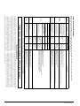
1
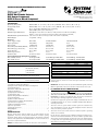
I56-2967-005R
INSTALLATION AND MAINTENANCE INSTRUCTIONS
D4120 Duct Smoke Detector
D4S Sensor Component
D4P120 Power Board Component
3825 Ohio Avenue, St. Charles, Illinois 60174
1-800-SENSOR2, FAX: 630-377-6495
www.systemsensor.com
NOTE: The D4120 duct detector consists of D4P120 Power Board component and the D4S Sensor component.
Specifications
Operating Temperature:
Storage Temperature:
Humidity:
Air Velocity:
D4120 Footprint Dimensions:
D4120 & D4S: –4° to 158° F (–20° to 70° C) D4P120: –40° to 158° F (–40° to 70° C)
D4120 & D4S: –22° to 158° F (–30° to 70° C) D4P120: –40° to 158° F (–40° to 70° C)
0% to 95% Relative Humidity Non-condensing
100 to 4000 ft./min. (0.5 to 20.3 m/sec.)
Rectangular - 14.38 in L x 5 in W x 2.5 in D (37cm L x 12.7cm W x 6.36cm D)
Square - 7.75 in L x 9 in W x 2.5 in D (19.7cm L x 22.9cm W x 6.35cm D)
D4S/D4P120 Footprint Dimensions: 7.75 in L x 5 in W x 2.5 in D (19.7cm L x 12.7cm W x 6.35cm D)
D4120 Weight:
2.5 pounds; 1.14 kg
Electrical
Power supply voltage:
20-29 VDC
24 VAC 50-60-Hz
120 VAC 50-60 Hz
Input capacitance:
270 µF max.
270 µF max.
N/A
Reset Voltage:
3.0 VDC min.
2.0 VAC min.
10 VAC min.
Reset Time (with RTS451/RTS151): .03 to 0.3 sec.
.03 to 0.3 sec.
.03 to 0.3 sec.
Reset Time (by power down):
0.6 sec. max.
0.6 sec. max.
0.6 sec. max.
Power Up Time:
35 sec. max.
35 sec. max.
35 sec. max.
Alarm response time:
15 sec.
15 sec.
15 sec.
Sensitivity Test:
See detector label
See detector label
See detector label
Current Requirements (Using No Accessories)
Max. standby current
21 mA @ 24 VDC
65 mA RMS @ 24VAC 60Hz
20 mA RMS @ 120 VAC 60 Hz
Max. alarm current
65 mA @ 24 VDC
135 mA RMS @ 24 VAC 60 Hz
35 mA RMS @ 120 VAC 60 Hz
CONTACT RATINGS
Alarm initiation contacts (SPST)
Alarm auxiliary contatcs (DPDT)
ACCESSORY CURRENT LOADS AT 24 VDC
2.0A @ 30 VDC (resistive)
DEVICE
10A @30 VDC (resistive)
APA151/APA451
10A @250 VAC (resistive)
1
/2 HP @240 VAC
1
/4 HP @120 VAC
NOTE: Alarm auxiliary contacts shall not be connected to initiating circuits of
control panels. Use the alarm initiation contact for this purpose.
Supervisory Contacts (SPDT)
ALARM
n/a
30mA Max.
MHR/MHW
0mA
n/a
29mA Max.
0mA
n/a
12mA Max.
RTS451/RTS151
0mA
n/a
12mA Max.
RTS451KEY/RTS151KEY
12mA
n/a
12mA Max.
3mA Max.
16mA Max.
30mA Max.
3mA
16mA Max.
55mA Max.
RTS2-AOS
NOTE: Any combination of accessories may be used such that the given
accessory loads are: 110mA or less at the Aux output, and 50mA or less at the
Alarm output.
2.0A @ 125 VAC (resistive)
Table of Contents
Page
[1] Limitations of Duct Smoke Detectors. . . . . . . . . . . . . . . . . . . . . . . . . . 1
[2] Exploded View of Duct Smoke Detector Components . . . . . . . . . . . . . . 2
[3] General Description . . . . . . . . . . . . . . . . . . . . . . . . . . . . . . . . . . . . . . . 2
[4] Contents of Duct Smoke Detector Kit. . . . . . . . . . . . . . . . . . . . . . . . . . 2
[5] Detector Installation . . . . . . . . . . . . . . . . . . . . . . . . . . . . . . . . . . . . . . 2
[6] Sampling Tube Installation. . . . . . . . . . . . . . . . . . . . . . . . . . . . . . . . . . 3
[7] Measurement Tests . . . . . . . . . . . . . . . . . . . . . . . . . . . . . . . . . . . . . . . 3
[8] Field Wiring Installation Guidelines. . . . . . . . . . . . . . . . . . . . . . . . . . . 4
[9] Unit Configuration. . . . . . . . . . . . . . . . . . . . . . . . . . . . . . . . . . . . . . . . 5
[10] Detector Status Indication . . . . . . . . . . . . . . . . . . . . . . . . . . . . . . . . . 6
[11] Interconnection (Multiple Fan Shut Down). . . . . . . . . . . . . . . . . . . . . 6
[12] Verification of Operation . . . . . . . . . . . . . . . . . . . . . . . . . . . . . . . . . . 6
[13] Detector Cleaning Procedures. . . . . . . . . . . . . . . . . . . . . . . . . . . . . . . 7
[14] Sensor replacement. . . . . . . . . . . . . . . . . . . . . . . . . . . . . . . . . . . . . . 7
[15] Optional Accessories. . . . . . . . . . . . . . . . . . . . . . . . . . . . . . . . . . . . . 7
Wiring Diagrams . . . . . . . . . . . . . . . . . . . . . . . . . . . . . . . . . . . . . . . . . . 5-7
Warranty . . . . . . . . . . . . . . . . . . . . . . . . . . . . . . . . . . . . . . . . . . . . . . . . 8
Before Installing
Read the System Sensor Guide for Proper Use of Smoke Detectors in Duct
Applications (A05-1004), which provides information on detector spacing,
placement, zoning, wiring, and special applications. This manual is available
online at www.systemsensor.com. NFPA Standards 72 and 90A should also be
referenced for detailed information.
IMPORTANT: This detector must be tested and maintained regularly following
NFPA 72 requirements. The detector should be cleaned at least once a year.
[1] Limitations Of Duct Smoke Detectors
WARNING
The National Fire Protection Association has established that DUCT DETECTORS MUST NOT BE USED AS A SUBSTITUTE FOR OPEN AREA DETECTOR
PROTECTION as a means of providing life safety. Nor are they a substitute for
early warning in a building’s regular fire detection system.
System Sensor supports this position and strongly recommends that the user
read NFPA Standards 90A, 72, and 101. The D4120 Air Duct Smoke Detectors
are listed per UL 268A.
This device will not operate without electrical power. Fire situations may
cause an interruption of power. The system safeguards should be discussed
with your local fire protection specialist.
This device will not sense smoke unless the ventilation system is operating
and the cover is installed.
For this detector to function properly, it MUST be installed according to the instructions in this manual. Furthermore, the detector MUST be operated within
ALL electrical and environmental specifications listed in this manual. Failure
to comply with these requirements may prevent the detector from activating
when smoke is present in the air duct.
NOTICE: This manual shall be left with the owner/user of this equipment.
SS-300-000
TROUBLE
12.5mA
RA400Z/RA100Z
RTS2
2.0A @ 30 VDC (resistive)
STANDBY
1
I56-2967-005R
[2] Figure 1. Exploded View of Duct Smoke Detector Components:
EXHAUST TUBE
4-WIRE
POWER BOARD
POWER BOARD MODULE COVER
SENSOR MODULE
COVER
METAL
SAMPLING TUBE
(sold seperately)
SENSOR HEAD
MAGNET TEST LOCATION
H0549-06
Exception: Installation of duct detectors can be on or within a commercial
packaged rooftop heating and air-conditioning system, fire/smoke dampers
and economizers. They may be mounted in either the supply and/or return air
section as determined by local code.
Once a suitable location is selected, determine if the detector is to be mounted
in a side-by-side “rectangular” configuration or a top-over-bottom “square”
configuration as shown in Figure 2. If mounting in the square configuration,
remove the rear attachment screw, rotate the unit at the hinge, and replace the
screw into the new attachment hole as shown in Figure 2. Do NOT remove
the hinge screw during this process. Final installation approval shall be based
upon passing section 7.2.2 and/or 8.2.4 tests.
[3] General Description
Smoke introduced into an air duct system will be distributed throughout the
entire building. Smoke detectors designed for use in air duct systems are used
to sense the presence of smoke in the duct.
Model D4120 and D4S Duct Smoke Detectors utilize 4-wire photoelectric technology for the detection of smoke. This detection method, when combined
with an efficient housing, samples air passing through the duct allowing detection of a developing hazardous condition. When sufficient smoke is sensed,
an alarm signal is initiated and appropriate action can be taken to shut off
fans, blowers, change over air handling systems, etc. These actions can facilitate the management of toxic smoke and fire gases throughout the areas
served by the duct system.
Figure 2:
The D4120 and D4P120 detectors are designed to operate on 24 VDC/VAC or
120 VAC. Alarm and supervisory relay contacts are available for control panel
interface (alarm initiation), HVAC control, and other auxiliary functions. Auxiliary relays are provided for fan shut down. Detector interconnection provides
signaling of up to 50 other detectors in the loop for multiple fan shut down.
These detectors are not designed for 2-wire applications.
REMOVE SCREW AND PIVOT
DETECTOR AS SHOWN BELOW.
REPLACE SCREW
TO SECURE DETECTOR
IN PLACE.
[3.1] Detector Feature Set
-Utilizes 2D51 plug-in head
-2 sensors to 1 power board capability
-Cover missing signal
-Sampling tubes install from front or rear of detector
-Compatible with existing accessories
H0550-00
[4] Contents Of The Duct Smoke Detector Kit
1. Sensor/power board assembly and cover(s)
2. Three #10 sheet metal screws for mounting
3. Drilling template
4. One sampling tube end cap
5. One plastic exhaust tube
NOTE: A sampling tube must be ordered to complete the installation. It must
be the correct length for the width of the duct where it will be installed.
See Table 1 on page 3 to determine the inlet tube required for different duct
widths.
[5] Detector Installation
[5.1] Verify Air Flow Direction And Velocity
Model D4120 detectors are designed to be used in air handling systems with
air velocities of 100 to 4000 feet per minute. Duct widths from 6 inches to 12
feet can be accommodated. Be sure to check engineering specifications to
ensure that the air velocity in the duct falls within these parameters. If necessary, use a velocity meter (anemometer) to check the air velocity in the duct.
[5.3] Drill the Mounting Holes
Remove the paper backing from the mounting template supplied. Affix the
template to the duct at the desired mounting location. Make sure the template
lies flat and smooth on the duct.
[5.3.1] For rectangular side-by-side mounting configuration:
Center punch at (4) target centers: (2) “A” for sampling tubes and (2) “B” for
the rectangular configuration mounting tabs as shown on mounting template.
Drill pilot holes at target “A” centers and cut two 1.375 inch diameter holes
using a 13/8 inch hole saw or punch. Drill .156 inch diameter holes using a 5/32
inch drill at target “B” centers.
[5.3.2] For square top-over-bottom mounting
configuration or D4S sensor component mounting:
Center punch at (4) target centers: (2) “A” for sampling tubes and (2) “C” for
the square configuration mounting tabs as shown on mounting template. Drill
pilot holes at target “A” centers and cut two 1.375 inch diameter holes using
a 13/8 inch hole saw or punch. Drill .156 inch diameter holes using a 5/32 inch
drill at target “C” centers. If desired, drill an additional .156 inch hole at the
location of one of the mounting tabs on the lower housing.
[5.2] Determine Mounting location and Configuration
On ducts wider than 18 inches it is recommended that the detector be
mounted downstream of a bend, obstruction in the duct, or the supply or
return air inlet.
[5.4] Secure the Duct Detector to the Duct
Use two (rectangular configuration) or three (square configuration) of the provided sheet metal screws to screw the duct detector to the duct.
CAUTION: Do not overtighten the screws.
SS-300-000
2
I56-2967-005R
ing out of the duct, select a shorter tube using Table 1. Otherwise, trim
the tube to leave approximately 1 to 2 inches extending outside the duct.
Plug the end with the end cap and tape closed any holes in the protruding section of tube. Be sure to seal the duct where the tube protrudes.
Figure 4.
[6] Sampling Tube Installation
[6.1] Sampling Tube Selection
The sampling tube must be purchased separately. Order the correct length,
as specified in Table 1, for width of the duct where it will be installed. It is
recommended that the sampling tube length extend at least 2/3 across the duct
width for optimal performance.
Table 1. Sampling tubes recommended for different
duct widths:
/˝
1 4
Outside Duct Width
Sampling Tube Recommended*
Up to 1 ft.
DST1
1 to 2 ft.
DST1.5
2 to 4 ft.
DST3
4 to 8 ft.
DST5
8 to 12 ft.
DST10 (2-piece)
2˝
3 4
/˝
HOLE
H0215-00
*Must extend a minimum of /3 the duct width. These sampling tubes can
only be used with new InnovairFlex duct smoke detectors.
The sampling tube is always installed with the air inlet holes facing into the
air flow. To assist proper installation, the tube’s connector is marked with an
arrow. Make sure the sampling tube is mounted so that the arrow points into
the airflow as shown in Figure 3. Mounting the detector housing in a vertical
orientation is acceptable provided that the air flows directly into the sampling
tube holes as indicated in Figure 3. The sampling tube and exhaust tube
can be mounted in either housing connection as long as the exhaust tube is
mounted downstream from the sampling tube.
[6.3] Modifications of Sampling Tubes
There may be applications where duct widths are not what is specified for the
installation. In such cases, it is permissible to modify a sampling tube that is
longer than necessary to span the duct width.
Use a 0.193 inch diameter (#10) drill and add the appropriate number of holes
so that the total number of holes exposed to the air flow in the duct is 10 to 12.
Space the additional holes as evenly as possible over the length of the tube.
Figure 3. Air duct detector sampling tube:
SAMPLING TUBE ENDCAP
NOTE: This procedure should only be used as a temporary fix and is not intended as a substitute for ordering the correct length tubes.
[6.4] Remote Sampling Tube Installation
The detector arrangement can also incorporate remote mounting of the sampling tube and/or exhaust tube. In this case both the detector, sampling tube
and exhaust tube (if included) should be rigidly mounted to withstand the
pressure and vibrations caused by the air velocity. The location of the detector’s sampling tube should be such that there is uniform airflow in the cross
section area.
AIR FLOW
DIRECTION
H0551-00
The pressure differential across the sampling and exhaust ports in the detector
housing shall be verified to be between 0.01 and 1.11 inches of water. Do so
by measuring the pressure difference between the inlet and outlet ports on the
detector housing using a manometer as described in Section 7.1.
CAUTION: The sampling tube end cap, included with the detector, is critical to proper operation of the duct smoke detector. The end cap is needed to
create the proper air flow to the sensor of the duct smoke detector. Once any
sampling tube length adjustments are made, plug the end of the sampling tube
with the provided end cap.
[7] Measurement tests
[7.1] air flow
The D4120 is designed to operate over an extended air speed range of 100 to
4000 FPM. To verify sufficient sampling of ducted air, turn the air handler on
and use a manometer to measure the differential pressure between the two
sampling tubes. The differential pressure should measure at least 0.01 inches
of water and no more than 1.11 inches of water. Because most commercially
available manometers cannot accurately measure very low pressure differentials, applications with less than 500 FPM of air speed may require one of the
following: 1) the use of a current-sourcing pressure transmitter (Dwyer Series
607) per Section 7.2, or 2) the use of aerosol smoke per section 12.5.3.
A plastic exhaust tube is included with the unit to be installed if needed. Install into the housing connection that is downstream from the sampling tube
connection. The exhaust tube can be installed from the front or back of the
detector. A longer 1 foot exhaust tube, model ETX, is available as an accessory
in cases where the molded exhaust tube does not extend at least 2 inches into
the duct.
[6.2] Sampling Tube Installation
1.For tubes shorter than the width of the duct, slide the sampling tube,
with installed end cap, into the housing connection that meets the airflow first. Position the tube so the arrow points into the airflow as shown
in Figure 3. Per NFPA sampling tubes over 3 feet long should be supported at the end opposite the duct detector. In ducts wider than 8 feet,
work must be performed inside the duct to couple the other section of
the sampling tube to the section already installed using the 1/2 inch conduit fitting. Make sure that the holes on both sections of the air inlet
sampling tube are lined up and facing into the airflow.
2.For tubes longer than the width of the duct, the tube should extend out
of the opposite side of the duct. Drill a 3/4 inch hole in the duct opposite
the hole already cut for the sampling tube. Ensure that the sampling tube
is angled downward from the duct smoke detector to allow for moisture
drainage away from the detector. The sampling tube should be angled
at least 1/4” downward for every 12” of duct width per Figure 4. There
should be 10 to 12 holes spaced as evenly as possible across the width of
the duct. If there are more than 2 holes in the section of the tube extendSS-300-000
DETECTOR
NOTE: Air currents inside the duct may cause excessive vibration, especially
when the longer sampling tubes are used. In these cases, a 3 inch floor flange
(available at most plumbing supply stores) may be used to fasten the sampling tube to the other side of the duct. When using the flange/connector
mounting technique, drill a 1 to 11/4 inch hole where the flange will be used.
2
ARROW MUST FACE
INTO AIR FLOW
12˝
[7.2] Low Flow Air Flow Test using Dwyer Series 607
Differential Pressure Transmitter
Verify the air speed of the duct using an anemometer. Air speed must be at
least 100 FPM. Wire the Dwyer transmitter as shown in Figure 5. Connect the
leads of the meter to either side of the 1000Ω resistor. Allow unit to warm up
for 15 seconds. With both HIGH and LOW pressure ports open to ambient air,
measure and record the voltage drop across the 1000Ω resistor (measurement
1), 4.00 volts is typical. Using flexible tubing and rubber stoppers, connect the
HIGH side of the transmitter to the sampling tube of the duct smoke detector housing, and the LOW side of the transmitter to the exhaust tube of the
duct smoke detector housing. Measure and record the voltage drop across the
1000Ω resistor (measurement 2). Subtract the voltage recorded in measurement 1 from the voltage recorded in measurement 2. If the difference is greater
than 0.15 volts, there is enough air flow through the duct smoke detector for
proper operation.
3
I56-2967-005R
[8.1] Wiring Instructions
The D4120 and D4P120 detectors are designed for easy wiring. The housing
provides a terminal strip with clamping plates. The D4S housing provides 4
wiring terminals with clamping plates. Wiring connections are made by sliding the bare end of the wire under the plate, and tightening the clamping plate
screw. See Figure 7 on page 5 for system wiring.
Figure 5. Procedure for verifying air flow less than 500 FPM:
TO SAMPLING TUBE
TO EXHAUST TUBE
HIGH
LOW
[8.2] Sensor 2 Installation/Wiring
The power board is capable of controlling a second housed sensor. The second
sensor, model D4S, can be wired to the power board per the following:
DIFFERENTIAL
PRESSURE
TRANSMITTER
MODEL #607-01
1.Connect wires to the four wire terminals in the corner of the D4S sensor
housing designated as Tamper (Y,Y), +R, and –B. Route wires through the
conduit openings in the sensor housing and D4120 power board housing.
2.Connect the opposing ends of the wires to the terminal connections
marked “Sensor 2” on the Power board. See Figure 6 for reference. Ensure that wires are connected to the appropriate terminal locations. A
No. 0 or 1 phillips screwdriver should be used for terminal connection.
The tamper terminals are not polarity sensitive.
3.Adjust the middle dip switch on the power board to indicate (2) sensors
as shown in Figure 6.
4.The D4S can only be used with new InnovairFlex models and is not compatible with previously sold detectors.[9] Unit Configuration:
[9] unit configuration
A three position Dip Switch is included only on the D4P120 in order to configure the setup of the unit. One switch is used to determine it there are one
or two sensors connected to the Power Board. The second switch selects an
instantaneous or 7-minute tamper Delay. A tamper Condition indicates that
the cover of the sesor Housing has been removed or has not been secured
properly. The third switch is used to turn the Shutdown On Trouble feature
on or off. With this feature turned On, the Aux relay will switch states when
a Trouble Condition occurs.
15 TO 36
VDC SUPPLY
1000 OHM 5%
1 WATT RESISTOR
9 VOLT
BATTERY
9 VOLT
BATTERY
9 VOLT
BATTERY
VOLT METER FLUKE
MODEL 87 OR
EQUIVALENT
+
–
H0163-01
[8] field wiring installation Guidelines
All wiring must be installed in compliance with the National Electrical Code
and the local codes having jurisdiction. Proper wire gauges should be used.
The conductors used to connect smoke detectors to control panels and accessory devices should be color-coded to prevent wiring mistakes. Improper connections can prevent a system from responding properly in the event of a fire.
For signal wiring, (wiring between interconnected detectors or from detectors
to auxiliary devices), it is recommended that single conductor wire be no
smaller than 18 gauge.
*Trouble is indicated when the Supervisory Relay, switches state-Terminals 3 and 14 are open in a Trouble Condition
Causes of a Trouble Condition may be:
Smoke detectors and alarm system control panels have specifications for allowable loop resistance. Consult the control panel manufacturer’s specifications for the total loop resistance allowed for the particular control panel being
used before wiring the detector loop.
• Unit loses Power
• Cover Tamper Feature times out
• Wiring Problems between the Sensor and the Power Board
• Mismatch between number of sensors connected to the Power Board and
the Dipswitch setting
Figure 6. Optional sensor 2 configuration and wiring:
WIRING TERMINALS
D4S
D4S
SENSOR ONLY
NOTE: IF USING (2) D4S
SENSOR ONLY
COMPONENTS WITH
MODEL D4P120 POWER
BOARD COMPONENT, USE
SENSOR #1 TERMINALS
AND WIRE IN SAME
MANNER AS SHOWN FOR
SENSOR #2.
D4120
CO-LOCATED
24V AC/DC, 10
7, NO
24V AC/DC, 9
18, C
AUX OUT +, 19
8, NC
AUX OUT -, 20
17, NO
INT/AUX-, 1
INT+, 12
FIELD SELECTABLE
DIP SWITCHES
14, N0
R TEST, 11
3, C
R RESET, 2
13, NC
ACC +
5, NO
ACC -
4, C
7, NO
8, NC
24V AC/DC, 10
18, C
17, NO
24V AC/DC, 9
6, C
AUX OUT -, 20
AUX A
AUX OUT +, 19
14, N0
16, NC
SUP
INT/AUX-, 1
3, C
INT+, 12
13, NC
R TEST, 11
4, C
5, NO
SS-300-000
ALARM, 15
ACC -
ACC +
POWER
BOARD LED 2
SENSOR
POWER
LEDs
BOARD LED 1
120 VAC
B
-
SENSOR 2
R RESET, 2
OFF/ON TRBL SHUTDN
1/2 SENSORS
7/0 MIN TMPR DELAY
ALARM
B
6, C
Y
Y
TAMPER
B Y Y R
- TAMPER +
SENSOR 1
–
R
GROUND
SCREW
SENSOR #1
TERMINALS
Y
Y R
TAMPER +
+
16, NC
ALARM, 15
SENSOR #2
TERMINALS
TAMPER
Y
Y
R
+
B
–
SENSOR 2
D4120
AUX B
120
VAC INPUT
H0557-14
24 VAC/
DC INPUT
TEST/RESET
BUTTON
4
I56-2967-005R
Figure 7. System wiring diagram for 4-wire duct smoke detectors:
CAUTION
Do not loop wire under terminals when wiring detectors. Break wire runs to provide system supervision of connections.
POWER INPUTS (NOTE 1)
24VAC/DC
9
POWER INPUTS (NOTE 1)
120
VAC
120
VAC
24V
9
10
10
OR
OR
AUXILIARY CONTACTS
FOR FAN SHUTDOWN, ETC. (NOTE 2)
N.C.
16
AUX A
C.
N.O.
6
AUXILIARY CONTACTS
FOR FAN SHUTDOWN, ETC. (NOTE 2)
N.C.
AUX B
C.
N.O.
N.C.
8
18
7
16
17
SUPERVISORY CONTACTS
(NOTE 3)
UL/FM LISTED
4-WIRE
CONTROL PANEL
SUP N.O.
SUP C
14
3
AUX A
C.
6
N.O.
17
N.C.
AUX B
C.
N.O.
8
18
7
SUPERVISORY CONTACTS
(NOTE 3)
SUP N.O.
SUP C
14
3
EOL RESISTOR
SPECIFIED BY
PANEL
MANUFACTURER
+
ALARM
INITIATION
CONTACTS
(NOTE 4)
ALARM
INITIATION
LOOP
5
ALARM N.O.
4
ALARM C
ALARM
INITIATION
CONTACTS
(NOTE 4)
5
ALARM N.O.
4
ALARM C
H0558-07
FIRST DETECTOR IN THE LOOP
LAST DETECTOR IN THE LOOP
NOTE 1: 24V Power Inputs accept a non-polarized 24VDC or 24VAC 50-60Hz.
120VAC Power Inputs accept only 120VAC 50-60Hz. Connect power source to
appropriate terminals of each detector. See specifications for additional power
supply information.
[10] detector status indication
Detector Staus is indicated by the LED sensor, and the correcsponding LED on
the power board. The power board has two separate LED’s to indicate the status of each sensor connected to it. Refer to Table 3 on page 8 for more details.
NOTE 2: Auxiliary contacts shown in standby position. Contacts switch during alarm as indicated by arrows. Auxiliary contacts are not to be used for
connection to the control panel. See specifications for contact ratings.
[11] interconnection (multiple fan shut down)
When using the interconnect feature, an alarm from an initiating device will
switch the Aux Relays on the other devices interconnected.
NOTE 3: Supervisory contacts shown in standby position. Open contacts indicate a trouble condition to the panel. See specifications for contact ratings.
NOTE 4: Alarm Initiation contacts shown in standby position. Closed contacts
indicate an alarm condition to the panel. See specifications for contact ratings.
Table 2. Dip Switch Settings:
Designation
TRBL SHUTDN
SENSORS
MIN TMPR
DELAY
SS-300-000
Default
Selection
OFF
OFF
Aux relay does not switch states with a Trouble condition
ON
Aux relay switches states with a Trouble condition
1
7
Features
1
Only one sensor is connected the Power Board
2
Two sensors are connected to the Power Board
7
Provides a Trouble condition ( terminals 3 and 14 open) when Sensor Housing cover has
been removed or has been secured improperly for more than 7 minutes
0
Provides an instantaneous Trouble condition(terminals 3 and 14 open) upon cover removal
5
I56-2967-005R
[12.5] Detector Cleaning Procedures
Figure 8. Multiple Fan Shutdown
(interconnection of D4120’s):
D4120
120 VAC
120 VAC
10
7
10
7
9
18
9
18
19
8
19
8
20
1
12
INT/AUX–
INT+
17
6
16
15
20
C, AUX A
NC, AUX A
1
12
17
INT/AUX–
6
INT+
16
14
15
11
3
11
3
2
13
2
13
+
5
+
5
–
4
–
4
DETECTOR 1
SYSTEM CONTROL
POWER, FAN
CONTROL OR
THERMOSTAT
Notify the proper authorities that the smoke detector system is undergoing
maintenance, and that the system will temporarily be out of service. Disable
the zone or system undergoing maintenance to prevent unwanted alarms and
possible dispatch of the fire department.
D4120
C, AUX A
NC, AUX A
[12.5.1] Alarm Tests
1a.Test/Reset Button - Press and hold the test button located on the power
board cover for at least 2 seconds.
OR
1b.M02-04-00 Magnet Test (Magnet sold separately) - Place the painted surface of the magnet onto the MAGNET TEST location on the sensor cover
of unit (Figure 1).
OR
1c.Remote Test Accessory - See list on page 1.
The red alarm LED on the sensor and the power board should latch on,
as should any accessories (i.e. RA400Z/RA100Z, RTS451/RTS151). Verify
system control panel alarm status and control panel execution of all intended auxiliary functions (i.e fan shutdown, damper control, etc.).
2.The detector must be reset by the system control panel, front cover Test/
Reset button, or remote accessory.
3.To reset using the Test/Reset button on the power board cover simply
Press and release.
4. Verify airflow test per Section 7 has been performed.
[12.5.2] Smoke Response Tests
To determine if smoke is capable of entering the sensing chamber, visually
identify any obstructions. Plug the exhaust and sampling tube holes to prevent ducted air from carrying smoke away from the detector head, then blow
smoke such as cigarette, cotton wick, or punk directly at the head to cause
an alarm. REMEMBER TO REMOVE THE PLUGS AFTER THIS TEST, OR THE
DETECTOR WILL NOT FUNCTION PROPERLY.
50
DET.
MAX.
14
DETECTOR 2
SYSTEM CONTROL
POWER, FAN
CONTROL OR
THERMOSTAT
H0552-00
Figure 9. Multiple Fan Shutdown (interconnection of D4120
to DH100ACDC):
DH100ACDC
DH100ACDC
D4120
D4120
[12.5.3] Smoke Entry using Aerosol Smoke
This test is intended for low-flow systems (100-500 FPM). If the air speed is
greater than 500 FPM, use a conventional manometer to measure differential
pressure between the sampling tubes, as described in Section 7.1.
D4120
H0617-00
[11.1] Important Interconnection Notes:
• When using the interconnect feature, all interconnected units must be
powered using the same independent supply.
Drill a 1⁄4 inch hole 3 feet upstream from the duct smoke detector. With the air
handler on, measure the air velocity with an anemometer. Air speed must be
at least 100 FPM. Spray aerosol smoke* into the duct through the 1⁄4 inch hole
for five seconds. Wait two minutes for the duct smoke detector to alarm. If the
duct smoke detector alarms, air is flowing through the detector. Remove the
duct smoke detector cover and blow out the residual aerosol smoke from the
chamber and reset the duct smoke detector. Use duct tape to seal the aerosol
smoke entry hole.
• P
olarity must be maintained throughout the interconnect wiring.
Connect the INT+ terminal on unit 1 to the INT+ terminal on unit 2
and so on. Similarly, connect the INT/AUX- terminal on unit 1 to the
INT/AUX- terminal on unit 2 and so on.
• Up to 50 D4120 units may be interconnected.
• Up to 10 DH100ACDC units may be interconnected. Please note that
each of the 9 DH100ACDC units interconnected can be substituted by
three D4P120 units. Therefore, when using the interconnect feature a
single DH100ACDC can drive either 9 DH100ACDC’s or 27 D4120 units.
*Aerosol smoke can be purchased from Home Safeguard Industries at homesafeguard.com, model 25S Smoke Detector Tester, and Chekkit Smoke Detector Tester model CHEK02 and CHEK06 available from SDi. When used
properly, the canned smoke agent will cause the smoke detector to go into
alarm. Refer to the manufacturer’s published instructions for proper use of
the canned smoke agent.
NOTE: Alarm can be reset only at the initiating device and not at the devices
interconnected.
[12] verification of operation
[12.1] field selectable settings
Verify dip switch settings as per Table 2 on Page 5.
CAUTION
Canned aerosol simulated smoke (canned smoke agent) formulas will vary by
manufacturer. Misuse or overuse to these products may have long term adverse effects on the smoke detector. Consult the canned smoke agent manufacturer’s published instructions for any further warnings or caution statements.
[12.2] powering the unit
Apply 24 VDC power to 9 and 10 terminals on the D4P120 or apply 120 VAC on
terminals named 120VAC. See Figure 7 and electrical specifications for details.
[12.3] perform detector check
VERIFY STANDBY AND TROUBLE TEST per Table 3 on page 8. The use of a
remote accessory for visible indication of power and alarm is recommended.
NOTE: If an instantaneous tamper delay is selected a trouble may be indicated
with the cover installed.
[12.4] Sensitivity Verification
The sensitivity of the sensor is confirmed to be operating within its allowable
range each time the sensor and power board LEDs blink green every 5 seconds. Note in a maintenance condition the sensor LEDs will blink red every 5
seconds and power board will blink amber as depicted in Table 3 on page 8.
The maintenance condition indicates that the sensor is operating outside its
original factory preset sensitivity and shall be cleaned or replaced. See Section
9 for reference. This is a valid UL test.
SS-300-000
[12.6] Install The Cover
Install the covers making sure that the cover fits into the base groove. Tighten
the seven screws that are captured in the covers.
[13] detector cleaning procedures
Notify the proper authorities that the smoke detector system is undergoing
maintenance, and that the system will temporarily be out of service. Disable
the zone or system undergoing maintenance to prevent unwanted alarms and
possible dispatch of the fire department.
6
I56-2967-005R
[13.1] Detector Sensor
1. Remove the sensor to be cleaned from the system.
2.Remove the sensor cover by pulling outward on each of the four removal
tabs that hold the cover in place. See Figure 10.
3.Vacuum the screen carefully without removing it. If further cleaning is
required continue with Step 4, otherwise skip to Step 7.
4. Remove the chamber cover/screen assembly by pulling it straight out.
5.Use a vacuum cleaner or compressed air to remove dust and debris from
the sensing chamber.
6.Reinstall the chamber cover/screen assembly by sliding the edge over the
sensing chamber. Turn until it is firmly in place.
7.Replace the cover using the holes for the LEDs for alignment and then
gently pushing it until it locks into place.
8. Reinstall the detector.
[13.2] Reinstallation
1. Reinstall the detector in its housing.
2. Restore system power.
3. Perform Detector Check, Section 12.3.
4.Notify the proper authorities testing has been completed and the smoke
detector system is back in operation.
With the key switch selected, there is also the capability of obtaining a sensitivity measurement of the selected sensor using the SENS-RDR sensitivity
reader (sold separately).
Figure 11. Wiring diagrams for optional accessories:
ALARM
AUX OUT –
15
(+)
20
(–)
AUX OUT –
MHR/MHW
(OPTIONAL) AUDIO
ALERT
D4120
DUCT DETECTOR
(+)
15
ALARM
20
RED
(–)
D4120
DUCT DETECTOR
RA400Z(OPTIONAL)
REMOTE (LED)
ANNUNCIATOR
H0554-00
Figure 12. Wiring diagram for D4120 to APA151 or APA451:
APA151/451
D4120
10
9
19
COMMON 1
7 FIELD
INSTALLED
18 JUMPER
8
AUX OUT +
20 AUX OUT –
17
1
6
12
(RED LED) ALARM 2
16
15 ALARM
14
11 R TEST
Figure 10. Detector sensor exploded view:
SENSOR
COVER
(GREEN LED) POWER
3
2
R RESET
+
ACC +
–
ACC –
SUP, NO
SUP, C
3
13
5
4
NOTE: WIRING DIAGRAM SHOWN IS FOR D4120 4-WIRE DUCT SMOKE
DETECTOR SYSTEM EQUIPPED WITHOUT A CONTROL PANEL.
COVER
REMOVAL
TABS
NOTE: A TROUBLE CONDITION IS INDICATED
BY LOSS OF GREEN LED
SENSING
CHAMBER
COVER AND
SCREEN
H0584-02
Figure 13. Wiring diagram for D4120 to RTS451/RTS151/RTS451KEY/RTS151KEY:
RTS451/RTS451KEY
SENSOR
CHAMBER
9
FIELD
INSTALLED
JUMPER
C1009-00
NOTICE: If any unitary packaged air conditioning units are run during the
drywall installation phase of any building under construction to accelerate
the drying of joint compound, the subsequent sanding of those drywall joints
and resulting dust may compromise the sensor heads in duct smoke detectors.
To avoid this condition it is recommended that the sensor heads be removed
during the construction phase.
For additional information visit www.systemsensor.com for a detailed technical bulletin.
19
2
4
AUX OUT +
20 AUX OUT –
1
3
6
7
FIELD
18 INSTALLED
8 JUMPERS
17
6
12
(RED LED) 1
ALARM 5
(GREEN LED)
POWER
D4120
10
15 ALARM
11 R TEST
2
R RESET
+
ACC +
–
ACC –
16
14
3
SUP, NO
SUP, C
13
5
4
FOR RTS451KEY ONLY WITHOUT A CONTROL PANEL
H0582-17
Figure 14. Wiring diagram:
[14] Sensor Replacement (part no. 2D51)
1. Remove the sensor head by rotating counterclockwise.
2. Pull gently to remove it.
3.To replace the sensor head, align the mounting features and rotate clockwise into place.
[15] Optional accessories
[15.1] RTS451/RTS151/RTS451KEY/RTS151KEY Remote Test
Station
The RTS451/RTS151/RTS451KEY/RTS151KEY Remote Test Station facilitates
test of the alarm capability of the duct smoke detector as indicated in the
RTS451/RTS151/RTS451KEY/RTS151KEY manual. The D4120 duct smoke detector can be reset by the RTS451/RTS151/RTS451KEY/RTS151KEY. To install
the RTS451/RTS151/RTS451KEY/RTS151KEY, connect the device as shown in
Figure 13; wire runs must be limited to 25 ohms or less per interconnecting
wire. If a system control panel is used, the panel itself may require testing.
D4120/D4120W/D4P120
RTS2/RTS2-AOS
AUX (+)
AUX (-)
(+) AUX
ACC (+)
(+) ACC
ACC (-)
(-) AUX
(-) ACC
NOTE: If polarity of Acc. (+) and Acc. (—) are reversed,
an Amber LED on sensor 2 of the duct smoke detector
power board will exist indicating a trouble condition.
H0626-01
[15.2] RTS2/RTS2-AOS MULTI-SIGNALING ACCESSORY
The RTS2 and RTS2-AOS multi-signaling accessories are designed for use with
InnovairFlex 4-wire conventional duct smoke detectors only. The accessory
has two bicolored LEDs that indicate the sensor status of up to two connected
duct smoke detectors. The key switch on the unit can be used to select a connected duct detector sensor (either sensor1 or sensor 2), and the selected sensor can be tested or both sensors can be reset simultaneously using the test/
reset button. LED status indications include: Standby (green blink), Trouble
(amber), Maintenance (amber blink) and Alarm (red).
SS-300-000
7
I56-2967-005R
Table 3. Detector Status Indication
Description
Sensor
D4S
Alternating
Green/amber
every 1 second
Supervisory relay: Terminals 3 and 14 are closed
Alarm Relay: Terminals 4 and 5 are open.
Aux Relay does not switch states:Terminals 6 and 16 are closed,Terminals 8 and 18 are closed
Supervisory relay: Terminals 3 and 14 are closed.
Alarm Relay: Terminals 4 and 5 are open.
Aux Relay does not switch states:Terminals 6 and 16 are closed,Terminals 8 and 18 are closed
Status of Relays
Alternating
Green/amber
every 1 second
Power Board
D4P120
LED Status
NOTE: There are two LED’s on the Power board D4P120, each indicating the Status of the two sensors connected.
When there is only one sensor connected, LED2 will remain off.
Status
Off
At power-up or reset at the panel, the
sensor will take approx 35 seconds
RED Blink every 5
to initialize. Also occurs if the sensor
seconds
has been removed and restored in
Sensor
the base in the sensor housing.
Initialization
Sensor is missing during the seven
minute tamper Delay, if selected.
Off
Green blink every 5
seconds on first
sensor.
No second sensor.
LED1 Green
blink every 5
seconds
LED2 Amber
solid
LED1 Green
blink every 5
seconds
LED2 Amber
solid
Supervisory relay: Terminals 3 and 14 are closed
Alarm Relay: Terminals 4 and 5 are closed.
Aux Relay switches states: Terminals 6 and 16 are open, Terminals 8 and 18 are open
Supervisory relay: Terminals 3 and 14 are open.
Alarm Relay: Terminals 4 and 5 are open.
Aux Relay does not switch states with no shutdown on Trouble selected:
Terminals 6 and 16 are closed. Terminals 8 and 18 are closed.
Aux Relay Switches states with shutdown on Trouble selected:
Terminals 6 and 16 are open, Terminals 8 and 18 are open
Supervisory relay: Terminals 3 and 14 are open.
Amber Blink
Alarm Relay: Terminals 4 and 5 are open.
every 5 seconds
Aux Relay does not switch states:Terminals 6 and 16 are closed,Terminals 8 and 18 are closed
.Unit loses Power
Off
.Cover Tamper Delay times out
Green Blink every 5
Amber solid
seconds
1 sensor connected,2 selected
Green blink every 5
seconds on first
sensor.
LED's off on second
sensor
Solid Red
Amber solid
Off
2 sensors connected,1 selected
Solid Red
Supervisory relay: Terminals 3 and 14 are closed
Unit has Power and it is not in
Green Blink every 5 Green Blink
Alarm Relay: Terminals 4 and 5 are open.
initialization, Trouble, Maintenance or
seconds
every 5 seconds
Aux Relay does not switch states: Terminals 6 and 16 are closed, Terminals 8 and 18 are closed
Alarm.
Unit detects smoke
.Mismatch between the number of
sensors connected and the Dip
Switch setting
.Wiring Problems between the
Sensor and the Power Board
Sensor D4S is outside it's UL
RED Blink every 5
Maintenance approved sensitivity limits and needs
seconds
to be cleaned or replaced.
Trouble
Alarm
Standby
NOTE: If any other visual indication is noted contact System Sensor technical support at 1-800-SENSOR2.
Please refer to insert for the Limitations of Fire Alarm Systems
Three-Year Limited Warranty
System Sensor warrants its enclosed product to be free from defects in materials and
#__________, 3825 Ohio Avenue, St. Charles, IL 60174. Please include a note describing
workmanship under normal use and service for a period of three years from date of
the malfunction and suspected cause of failure. The Company shall not be obligated to
manufacture. System Sensor makes no other express warranty for the enclosed product.
replace units which are found to be defective because of damage, unreasonable use,
No agent, representative, dealer, or employee of the Company has the authority to inmodifications, or alterations occurring after the date of manufacture. In no case shall the
crease or alter the obligations or limitations of this Warranty. The Company’s obligation
Company be liable for any consequential or incidental damages for breach of this or any
of this Warranty shall be limited to the replacement of any part of the product which
other Warranty, expressed or implied whatsoever, even if the loss or damage is caused by
is found to be defective in materials or workmanship under normal use and service
the Company’s negligence or fault. Some states do not allow the exclusion or limitation of
during the three year period commencing with the date of manufacture. After phoning
incidental or consequential damages, so the above limitation or exclusion may not apply
System Sensor’s toll free number 800-SENSOR2 (736-7672) for a Return Authorization
to you. This Warranty gives you specific legal rights, and you may also have other rights
number, send defective units postage prepaid to: System Sensor, Returns Department, RA
which vary from state to state.
I56-2967-005R
©2012 System Sensor
8
SS-300-000