1
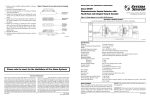
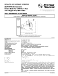
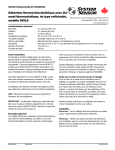
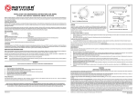
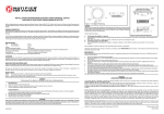
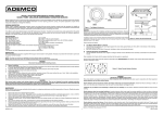
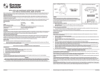
INSTALLATION AND MAINTENANCE INSTRUCTIONS
2112/24TSRB Photoelectronic
Smoke Detector
Specifications
Diameter:
Height (including mounting bracket):
Weight:
Operating Temperature Range:
Operating Humidity Range:
Latching Alarm:
Heat Sensor:
Electrical Ratings
System Voltage
Maximum Ripple Voltage:
Standby Current:
Alarm Current:
A Division of Pittway
3825 Ohio Avenue, St. Charles, Illinois 60174
1-800-SENSOR2, FAX: 630-377-6495
5.5 inches (140 mm)
1.7 inches (43 mm)
5.3 oz. (150 g)
32° to 100°F (0° to 39°C)
10% to 93% relative rumidity, noncondensing
Reset by momentary power interruption
135°F fixed temperature electronic thermistor
nominal:
12 or 24 VDC
Minimum:
8.5 VDC
Maximum:
35 VDC
30% of nom. voltage (peak to peak)
15 mA maximum
at 12V: 38 mA maximum
at 24V:
45 mA maximum
Reset Voltage:
0.8 VDC minimum
Reset Time:
0.3 seconds maximum
Start-up Time:
30 seconds maximum (after 30 second reset)
Supervision and Alarm Initiation Contact Ratings
Resistive or inductive load (60% power factor)
Form A:
0.5A @ 30 VAC/DC
Before Installing
Please thoroughly read System Sensor manual I56-407,
Guide for Proper Use of System Smoke Detectors, which
provides detailed information on detector spacing, placement, zoning, wiring, and special applications. Copies of
this manual are available at no charge from System Sensor.
mounting bracket and plug-in screw terminal block that
can be prewired to the system, allowing the detector to
be easily installed or removed for cleaning. The detector’s
sensitivity can be tested in place using the MOD400R Test
Module (available separately from System Sensor).
The 2112/24TSRB features a supervisory relay that supervises the power and the sensitivity of the detector. When
the power to the detector is lost, the supervisory relay
opens instantaneously. Where as, when the detector deviates from its sensitivity range indicating the need for maintenance, the supervisory relay opens after a maintenance
condition has continuously existed for 30 to 35 minutes.
NOTICE: This manual should be left with the owner/user
of this equipment.
IMPORTANT: This detector must be tested and maintained
following NFPA 72 requirements. The detector should be
cleaned at least once a year.
General Description
The Model 2112/24TSRB is a 4-wire photoelectronic smoke
detector that uses a state-of-the-art optical sensing chamber. This detector is designed to provide open area protection. It features a restorable, built-in, fixed-temperature
(135°F) thermal sensor.
An LED on the detector provides a local visual indication
of the detector’s status. If power is applied to the detector,
and it is functioning normally in standby, the status LED
blinks every ten seconds. The LED latches on in alarm and
quits flashing when the detector deviates from its sensitivity range.
Installation of this detector is simplified by the use of the
D200-61-00
1
I56-930-02
Figure 1. Surface mounting of 2112/24TSRB smoke
detector on 31/2-inch and 4-inch octagonal box:
The screw terminal block accepts 14 – 22 gauge wire. For
best system performance, all wiring should be installed in
separate grounded conduit. Do not mix fire system wiring
in the same conduit as any other electrical wiring. Twisted
pair may be used to provide additional protection against
electrical interference.
Smoke detectors and alarm system control panels have
specifications for allowable loop resistance. Consult the
control panel specifications for the total loop resistance
allowed for the control panel being used before wiring the
detector loops.
A78-2563-00
Mounting
The 2112/24TSRB detector is supplied with a mounting
bracket that permits the detector to be mounted:
1. To a single gang box, or
2. Directly to a 31/2-inch or 4 inch octagonal box, or
3. To a 4 inch square electrical box by using a plaster ring.
Wire connections are made by stripping about 1/4 inch of
insulation from the end of the feed wire, inserting the wire
into the appropriate terminal, and tightening the screw to
secure the wire in place.
NOTE: Trouble relay must be wired last in the circuit.
Tamper-resistant Feature
This detector includes a tamper-resistant feature that prevents its removal from the bracket without the use of a
tool. To make the detector tamper-resistant, remove the
smaller tab by breaking it at the scribed line on the tamper
resistant tab on the detector mounting bracket (see Figure
2), then install the detector. To remove the detector from
the bracket once it has been made tamper resistant, use
a small screwdriver to depress the tamper-resistant tab,
located in the slot on the mounting bracket, and turn the
detector counterclockwise.
Installation
WARNING
Remove power from the control unit or initiating device
circuits before installing detectors.
1. Wire the plug-in screw terminal block per Figure 3 and
plug the terminal block into the detector.
2. Align the arrows on the detector with the arrows on the
mounting bracket.
3. Turn the detector clockwise in the mounting bracket until it clicks into place.
4. After all detectors have been installed, apply power to
the control unit or initiating device circuits.
5. Test the detector as described in TESTING.
6. Reset the detector at the system control panel.
7. Notify the proper authorities the system is in operation.
Wiring Installation Guidelines
All wiring must be installed in compliance with the National Electrical Code, applicable local codes, and any special requirements of the local authority having jurisdiction.
Proper wire gauges should be used. The conductors used
to connect smoke detectors to control panels and accessory
devices should be color-coded to reduce the likelihood of
wiring errors. Improper connections can prevent a system
from responding properly in the event of a fire.
Figure 2. Smoke detector mounting bracket:
TAMPER RESISTANT TAB
(CUT OFF SMALL TAB TO
ACTIVATE TAMPER-RESIST
FEATURE)
TAMPER SLOT
(DEPRESS TAB TO
REMOVE DETECTOR)
ALIGNMENT
ARROWS
A78-2333-01
D200-61-00
2
I56-930-02
Figure 3. Wiring diagram for the 2112/24TSRB detector:
POWER +
TO
DETECTORS
+
+ P
W
R
– –
N.O.
N.O.
C
C
TRBL
TRBL
UL LISTED
CONTROL
PANEL
– –
–
+
+ P
W
R
EOL RESISTOR
SPECIFIED BY
PANEL
MANUFACTURER
A78-2336-02
+
INITIATING
LOOP
–
OPTIONAL CLASS A WIRING
B. Test Module (System Sensor Model No. MOD400R).
The MOD400R test module can be used with a DMM
or analog voltmeter to check the detector sensitivity as
described in the test module’s manual.
C. Smoke Entry Test
Hold a smoldering punk stick or cotton wick at the side
of the detector and gently blow smoke through the detector until the unit alarms.
D. Direct Heat Method (Hair dryer of 1000-1500 watts).
Direct the heat toward either of the side thermistors.
Hold the heat source about 12 inches from the detector
in order to avoid damage to the plastic. The detector will
reset only after it has had sufficient time to cool and the
power source has been momentarily interrupted.
Both smoke and heat detection testing are recommended
for verifying system protection capability.
CAUTION
Dust covers are an effective way to limit the entry of dust
into smoke detector sensing chambers. However, they may
not completely prevent airborne dust particles from entering the detector. Therefore, System Sensor recommends
the removal of detectors before beginning construction or
other dust producing activity. Be sure to remove dust covers
from any sensors that were left in place during construction
as part of returning the system to service.
Testing
NOTE: Before testing, notify the proper authorities that the
smoke detector system is undergoing maintenance
and will be temporarily out of service. Disable the
zone or system undergoing maintenance to prevent
unwanted alarms.
Detectors must be tested after installation and following
periodic maintenance. Test the 2112/24TSRB as follows:
A. Test Switch
1. A recessed test switch is located on the detector housing (See Figure 4).
2. Press and hold the recessed test switch with a 0.1
inch maximum diameter tool such as an allen wrench
or small screwdriver.
3. The detector’s LED should light within 5 seconds.
A detector that fails to activate with any of the above tests
should first be cleaned as outlined in MAINTENANCE. If
the detector still fails to activate, return it for repair.
Notify the proper authorities the system is in operation.
Figure 4. Top and side views showing position of test switch:
LED
TEST MODULE
SOCKET
D200-61-00
PUSH RECESSED
SWITCH WITH A
0.1″ MAX. DIAMETER TOOL
RECESSED TEST
SWITCH
A78-2564-00
3
I56-930-02
Maintenance
It is recommended that the detector be removed from
its mounting base to facilitate cleaning. The detector is
cleaned as follows:
NOTE: Before removing the detector, notify the proper
authorities that the smoke detector system is undergoing maintenance and will be temporarily out
of service. Disable the zone or system undergoing
maintenance to prevent unwanted alarms.
1. Remove the detector cover by prying away the four
side tabs with a small-bladed screwdriver, and then
pulling the cover from the base.
2. Vacuum the screen carefully without removing it. If
further cleaning is required continue with Step 3, otherwise skip to Step 8.
3. Remove the screen assembly by pulling it straight out
(see Figure 5).
4. Remove the sensing chamber cover by pulling it
straight out.
5. Clean the vaned chamber piece by vacuuming or blowing out dust and particles.
6. Replace the sensing chamber cover, aligning the arrow
on the top with arrow on the printed circuit board.
7. To replace the screen, place it over the chamber assembly, turning it until it snaps into place.
8. Replace the cover using the test module socket and
LEDs to align the cover and then gently pushing it until
it locks into place.
9. Reinstall the detector.
10. Test the detector as described in TESTING.
11. Reconnect disabled circuits.
12. Notify the proper authorities that the system is back on
line.
Figure 5. Removal of cover and screen for cleaning:
REMOVABLE
HOUSING
REMOVABLE
SCREEN
SENSING
CHAMBER
COVER
SENSING
CHAMBER
BASE
A78-2565-02
WARNING
The Limitations of Property Protection Smoke Detectors
This smoke detector is designed to activate and initiate emergency action, but will do so only when it is used in conjunction with an authorized
fire alarm system. This detector must be installed in accordance with
NFPA standard 72.
Smoke detectors will not work without power. AC or DC powered
smoke detectors will not work if the power supply is cut off.
Smoke detectors will not sense fires which start where smoke does
not reach the detectors. Smoldering fires typically do not generate a lot
of heat which is needed to drive the smoke up to the ceiling where the
smoke detector is usually located. For this reason, there may be large delays in detecting a smoldering fire with either an ionization type detector
or a photoelectric type detector. Either one of them may alarm only after
flaming has initiated which will generate the heat needed to drive the
smoke to the ceiling.
Smoke from fires in chimneys, in walls, on roofs or on the other side of a
closed door(s) may not reach the smoke detector and alarm it. A detector
cannot detect a fire developing on another level of a building quickly or
at all. For these reasons, detectors shall be located on every level and in
every bedroom within a building.
Smoke detectors have sensing limitations, too. Ionization detectors and
photoelectric detectors are required to pass fire tests of the flaming and
smoldering type. This is to ensure that both can detect a wide range of
types of fires. Ionization detectors offer a broad range of fire sensing capability but they are somewhat better at detecting fast flaming fires than
slow smoldering fires. Photoelectric detectors sense smoldering fires better than flaming fires which have little, if any, visible smoke. Because fires
develop in different ways and are often unpredictable in their growth, neither type of detector is always best, and a given detector may not always
provide early warning of a specific type of fire.
In general, detectors cannot be expected to provide warnings for fires
resulting from inadequate fire protection practices, violent explosions,
escaping gases which ignite, improper storage of flammable liquids like
cleaning solvents which ignite, other similar safety hazards, arson, smoking in bed, children playing with matches or lighters, etc. Smoke detectors
used in high air velocity conditions may have a delay in alarm due to
dilution of smoke densities created by frequent and rapid air exchanges.
Additionally, high air velocity environments may create increased dust
contamination, demanding more frequent maintenance.
Smoke detectors cannot last forever. Smoke detectors contain electronic
parts. Even though smoke detectors are made to last over 10 years, any
part can fail at any time. Therefore, smoke detectors shall be replaced after
being in service for 10 years. The smoke detector system that this detector is used in must be tested regularly per NFPA 72. This smoke detector
should be cleaned regularly per NFPA 72 or at least once a year.
Three-Year Limited Warranty
System Sensor warrants its enclosed smoke detector to be free from defects in materials and workmanship under normal use and service for a
period of three years from date of manufacture. System Sensor makes no
other express warranty for this smoke detector. No agent, representative,
dealer, or employee of the Company has the authority to increase or alter
the obligations or limitations of this Warranty. The Company’s obligation of this Warranty shall be limited to the repair or replacement of any
part of the smoke detector which is found to be defective in materials or
workmanship under normal use and service during the three year period
commencing with the date of manufacture. After phoning System Sensor’s
toll free number 800-SENSOR2 (736-7672) for a Return Authorization
number, send defective units postage prepaid to: System Sensor, Repair
D200-61-00
Department, RA #__________, 3825 Ohio Avenue, St. Charles, IL 60174.
Please include a note describing the malfunction and suspected cause
of failure. The Company shall not be obligated to repair or replace units
which are found to be defective because of damage, unreasonable use,
modifications, or alterations occurring after the date of manufacture. In no
case shall the Company be liable for any consequential or incidental damages for breach of this or any other Warranty, expressed or implied whatsoever, even if the loss or damage is caused by the Company’s negligence
or fault. Some states do not allow the exclusion or limitation of incidental
or consequential damages, so the above limitation or exclusion may not
apply to you. This Warranty gives you specific legal rights, and you may
also have other rights which vary from state to state.
4
I56-930-02
© System Sensor 1997