1
(2)
(1)
72-70762-01
Revision A January 2006
• Read the installation instructions before connecting the Power Injector to a
power source.
•Follow basic electricity safety measures whenever connecting the Power Injector to its
power source.
•This product relies on on the building installation for short-circuit (over current)
protection. Ensure a fuse or circuit breaker no larger than 120 VAC, 3A U.S. (240VAC,
1.5A international) is used on the phase conductor.
•A volatge mismatch can cause equipment damage and could pose a fire hazard. If the
voltage indicated on the label is different from the power outlet voltage, do not connect
the Power Injector to that particular outlet.
•The Power Injector Data In and Data & Power Out ports are shielded RJ-45 sockets.
Only RJ-45 data connectors should be connected to these sockets.
For the latest version of this guide go to: http://www.symbol.com/manuals/
11-8095311
315-271700
2-484441
01-40-96-52-21
France
7020-1718
Denmark/Danmark
1-800-672-906
Australia
0800 328 2424
United Kingdom
1-800-653-5350
1-631-738-2400
United States
+47 2232 4375
Norway/Norge
5-520-1835
Mexico/México
6074-49020
Germany/Deutschland
9 5407 580
Finland/Suomi
1-505-5794-0
Austria/Österreich
+65-6796-9600
Asia/Pacific
905-629-7226
Canada
• Power Injector (pt # AP-PSBIAS-1P2-AFR)
Inspect the package contents and report any missing or damaged items to your sales
representative. The packages should contain the following:
Verifying Package Contents
Installation Guide
Before using the unit, it must be configured to operate in the facility’s network and run your
applications. If you have a problem running your unit or using your equipment, contact your
facility’s Technical or Systems Support. If there is a problem with the equipment, they will
contact the Symbol Support Center:
1-Port Power-over-Ethernet
Power Injector
This guide is intended for the technician responsible for installing the Symbol Power Injector.
It assumes the technician is familiar with basic Ethernet LAN-based networking and device
installation concepts. This guide provides specifications, procedures and guidelines to use
during the installation process. This guide does not provide site-specific installation
procedures. For detailed site-specific installation procedures, refer to the site-specific
documentation derived from site survey and site network analysis.
To the Installer
Service Information
• Interconnection option with other Power Injector units.
•Only trained and qualified personnel should install and remove the Power Injector.
•A power cord is not supplied with the device. Use only a correctly rated power cord that’s
certified, as appropriate, for the country of operation.
• The power cord must be a three-conductor type (two current carrying conductors and one
ground conductor) terminated on one end by an IEC 60320 appliance coupler (for Power
Injector connection) and on the other end by a plug containing a ground (earth) contact.
• The power cord must be rated for a minimum of 250VAC RMS operation, with a minimum
rated current capcity of 5A [or a minimum wire gauge of 18AWG (0.75mm²)].
• The AC wall-socket outlet must be near the Power Injector and easily accessible.
• The Power Injector Data and Data & Power interfaces are qualified as SELV (Safety
Extra-Low Voltage) circuits according to to IEC 60950. These interfaces can only be
connected to SELV interfaces on other equipment.
Before operating any equipment, review this document for any hazards associated with
installation and use of the device. Also, review standard practices for preventing accidents.
Safety Information
•Supports standard 10/100BaseT Ethernet networks over a standard TIA/EIA-568
Category 5 (or higher) cabling
Ethernet Interface
Input (Data In)
Preparing for Site Installation
The Power Injector can be installed free standing, on an even horizontal surface or wall
mounted using the power injector’s wall mounting key holes.
•Verify the device receiving converged power and Ethernet from the Power Injector is a
product approved by Symbol (AP100, AP200, AP300 and AP-5131).
58.5mm
31mm
145mm
450gr
•Do not block or cover airflow to the Power Injector.
Environmental Specifications
Operating Temperature
0°C to 40°C (32°F to 104°F)
Storage Temperature
-20°C to 70°C (-4°F to 158°F)
Operating Humidity
10% to 93% Non-condensing
Storage Humidity
10% to 93% Non-condensing
•Independent power controller (SPEAR™), CPU controller and input (Data) and output
(Data + Power) shielded RJ-45 connectors
Installation
The following guidelines should be adhered to before cabling the Power Injector to the Ethernet
source and Symbol device:
Technical Specifications
Electrical Specifications
Input Voltage
Maximum Output Power
Nominal Output Voltage
The Power Injector has the following features:
Netherlands/Nederland
Caution - Using the Power Injector with an unsupported Symbol device could
render the device inoperable and void your warranty.
Italy/Italia
•This Power Injector Installation Guide (72-70762-01)
•AP 300
Spain/España
Warnings
91 324 40 00
Inside Spain
AP-5131
South Africa
+34 91 324 40 00
Outside Spain
to AP-5131 LAN
Port
84452900
Power
Injector
Sweden/Sverige
•Standalone or wall mount installation support
Physical Specifications
Width
Height
Depth
Weight
•AP 200
•AP-5131
Power
1-800-347-0178 Inside US
+1-954-255-2610 Outside US
A separate Power Injector is required for each device comprising the network.
The Symbol Power Injector supports the following Symbol device product families (all models
of the those listed):
•Port Status and Main power LED indicators
•AP 100
Data
Latin America
Sales Support
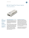
The Power Injector is a small lightweight unit with a RJ-45 Ethernet cord input connector from
the hub on the front right-hand side of the unit and a RJ-45 data and power output connector
to the AP on the front left-hand side of the unit. On the back of the unit is a 110-220 VAC power
input.
Product Description
The Symbol Power Injector (pt # AP-PSBIAS-1P2-AFR) is a single-port, 802.3af compliant Power
over Ethernet hub combining low-voltage DC with Ethernet data in a single cable connecting
to an AP. The Power Injector’s single DC and Ethernet data cable creates a modified Ethernet
cabling environment eliminating the need for separate Ethernet and power cables.
Contact local distributor or call
+44 118 945 7360
When users purchase a Symbol WLAN solution, they often need to place access points in
obscure locations. In the past, a dedicated 24-hour, 90-264 VAC power source was required for
each access point in addition to the Ethernet infrastructure. This often required an electrical
contractor to install power drops at each access point location. With the Symbol Power Injector
solution (pt # AP-PSBIAS-1P2-AFR), centralized power can be provided for devices without a
local power supply for each.
Europe/Mid-East
Distributor Operations
Introduction
90VAC to 264VAC (47Hz - 63Hz)
.15.4 W
48VDC
Ethernet 10/100Base-T
(RJ-45 female socket)
•Keep the Power Injector away from excessive heat, humidity, vibration and dust.
•The Power Injector is not a repeater, and does not amplify the Ethernet data signal. For
optimal performance, ensure the Power Injector is placed as close as possible to the
network data port. Do not configure the cable length between the Ethernet network
source, the Power Injector and the Symbol AP beyond 100 meters (333ft).
Cabling the Power Injector
To install the Power Injector to an Ethernet data source and Symbol device:
Caution - Ensure AC power is supplied to the Power Injector using an AC cable
with an appropriate ground connection approved for the country of operation.
•Meets the IEEE 802.3af standard
Output (Data & Power Out)
•Universal AC Input: 110/220 V, 60/50 Hz.
Ethernet 10/100Base-T, plus 48VDC
RJ-45 female socket, with DC voltage
on pairs 7-8 and 4-5
•Minimum port output continuous allowable power of 15.4W at 48V
(minimum 12.95W at the PDTE)
Wireless LAN
1. Connect the Power Injector to an AC outlet (110VAC to 220VAC).
2. Connect RJ-45 Ethernet cable between the network data supply (host) and the Power
Injector Data In connector.
3. Connect a RJ-45 Ethernet cable between the Power Injector Data & Power Out connector
and the Symbol device receiving converged power and Ethernet.
•Underload, overload, short-circuit & under/over voltage port protection.
(3)
(4)
(5)
(6)
Ensure the cable length from the Ethernet source (host) to the Power Injector and Symbol
device receiving converged power and Ethernet does not exceed 100 meters (333 ft).
Troubleshooting
The following potential Power Injector problem scenarios should be addressed as follows:
Power Injector does not power up properly
1.
2.
3.
Verify the power cord power cord is operational for the intended country of operation
Verify the voltage at the power inlet is between 100 and 240 VAC.
Remove and reapply power to the Power Injector and verify the LED behavior during the
powering sequence.
A Power Injector port indicator is not illuminated and the Symbol AP does
not operate
1.
2.
3.
4.
5.
6.
The Power Injector did not detect the AP and thus the port is not enabled.
Ensure you are using a standard 5/5e/6, straight-wired cable with four pairs.
Verify the input Ethernet cable is connected to the Power Injector Data In port.
Verify the Symbol AP is connected to the Power Injector Data & Power port.
Reconnect the Symbol AP to a different Power Injector. If the AP receives power, there
is probably a faulty port or RJ-45 connection on the Power Injector.
Verify there is not a short over any of the twisted pair cables or over the RJ-45
connectors.
Symbol AP receives power but no Ethernet
The Power Injector has no On/Off power switch. The Power Injector receives power and is
ready for Symbol device connection and operation as soon as AC power is applied.
Multiple Power Injector Installations
1.
2.
3.
4.
Each Power Injector has a coupling rail designed to connect Power Injectors together to support
multiple device installations. Align the power injectors and slide the units together using the
coupling rail to connect the units. Cable each device as described in the Cabling the Power
Injector section of this document. Only one Symbol device (AP 100, AP 200, AP 300 or
AP-5131) can be powered from a single Power Injector.
5.
Verify the Ethernet cable is connected to an active hub or switch port on the network.
Verify the port indicator on the front panel is continuously illuminated.
Verify you are using a standard UTP/FTP Category 5 straight (non-crossover) cabling
with all four pairs.
Ensure the Ethernet cable length is less than 100 meters from the Ethernet data source
to the Power Injector.
Reconnect the Symbol AP to a different Power Injector. If the AP receives power, there
is probably a faulty port or RJ-45 connection on the Power Injector.
Power Injector is receiving
power from AC outlet
Indicates a device is
connected to the
Power Injector’s outgoing
Data & Power cable
Output voltage source is
out of range
(8)
Symbol does not assume any product liability arising out of, or in connection with, the
application or use of this product, circuit, or application described herein.
Symbol Services Homepage
http://www.symbol.com/services/
No license is granted either expressly or by implication, estoppel, or otherwise under any
Symbol Technologies, Inc., intellectual property rights. No license is granted, either expressly
or by implication estoppel, or otherwise under any patent right or patent, covering or relating
to any combination, system, apparatus, machine, material, method or process in which Symbol
products might be used. An implied license exists only for equipment, circuits and subsystems
contained in Symbol products.
Symbol Software Updates
http://www.symbol.com/services/downloads/
Symbol Developer Program Web Site
http://devzone.symbol.com/
Additional Information
Obtain additional information by contacting Symbol at:
• 1-800-722-6234, inside North America
Symbol and the Symbol logo are registered trademarks of Symbol Technologies, Inc. Other
product names mentioned in this guide may be trademarks or registered trademarks of their
respective companies and are hereby acknowledged.
Symbol Technologies, Inc.
One Symbol Plaza
Holtsville, N.Y. 11742-1300
• +1-631-738-5200, in/outside North America
• http://www.symbol.com/
http://www.symbol.com
(11)
Regulatory Information
All Symbol devices are designed to comply with rules and regulations in locations they are sold
and will be labeled as required. Any changes or modifications to Symbol Technologies equipment,
not expressly approved by Symbol Technologies, could void the user’s authority to operate the
equipment.
(13)
Local language translations are available at the following website:
http://www.symbol.com/services/manuals/.
• Serial number of unit
EMI Compliance: Category 5 foiled twisted-pair cables must be used to ensure compliance with
Class B emission limits.
• Model number or product name
Radio Frequency Interference Requirements
• Software type and version number
Note: This equipment has been tested and found to comply with
the limits for a Class B digital device, pursuant to Part 15 of the
Tested to Comply
FCC rules. These limits are designed to provide reasonable
With FCC Standards
protection against harmful interference in a residential
For Home or Office Use
installation. This equipment generates, uses and can radiate
radio frequency energy and, if not installed and used in accordance with the instructions, may
cause harmful interference to radio communications. However there is no guarantee that
interference will not occur in a particular installation. If this equipment does cause harmful
interference to radio or television reception, which can be determined by turning the equipment
off and on, the user is encouraged to try to correct the interference by one or more of the following
measures:
Symbol Technologies Inc.
For sales and product information:
Symbol Technologies, Inc.
One Symbol Plaza
Holtsville, New York 11742-1300
Telephone: 1-631-738-2400/1-800-SCAN 234
Fax: 1-631-738-5990
For product support and service:
Symbol Global Support Center:
Telephone: 1-800-653-5350, +1-631-738-6213 (Outside North America)
Fax: 631-563-5410
Email: [email protected]
Green (Blinking)
MySymbolCare - RMA repair requests
http://www.symbol.com/services/msc/msc.html
Symbol Technologies provides its customers with prompt and accurate customer support. Use the
Symbol Support Center as the primary contact for any technical problem, question or support issue
involving Symbol products. If the Symbol Customer Support specialists cannot solve a problem,
access to all technical disciplines within Symbol becomes available for further assistance and
support. Symbol Customer Support responds to calls by email, telephone or fax within the time
limits set forth in individual contractual agreements.
Inside North America, contact Symbol at:
Port
Copyright © 2006 by Symbol Technologies, Inc. All rights reserved.
Comprehensive On-line support is available at the MySymbolCare Web-site. Registration is free
and a variety of services can be linked through this Web-portal.
Customer Support
North American Contacts
AC (Main)
Copyright
No part of this publication may be modified or adapted in any way, for any purposes without
permission in writing from Symbol Technologies (Symbol). The material in this guide is subject
to change without notice. Symbol reserves the right to make changes to any product to improve
reliability, function or design.
Web Support sites
(9)
The Power Injector demonstrates the following LED behavior under normal and/or problematic
operating conditions:
Green (Steady)
For other sales offices, use the Symbol Services Web site for contact information
http://www.symbol.com/services/howto/howto_contact_us.html
Statement of Compliance
Symbol Technologies, Inc., hereby declares that this device is in compliance with all the
applicable Directives, 89/336/EEC, 73/23/EEC. A Declaration of Conformity may be obtained
from http://www2.symbol.com/doc/
This product is covered by one or more of the patents listed on the Web site:
www.symbol.com/patents
When contacting Symbol Customer Support, please provide the following information:
LED
Outside North America, contact Symbol at:
Symbol Technologies, Inc.
Symbol Place
Winnersh Triangle, Berkshire, RG41 5TP
United Kingdom
Telephone: 0800-328-2424 (Inside UK), +44 118 945 7529 (Outside UK)
Patents
(7)
Power Injector LED Indicators
Marking and European Economic Area (EEA)
International Contacts
Or see the Symbol Web for additional local contact numbers http://www.symbol.com/services/
contactsupport
• Reorient or relocate the receiving antenna
• Increase the separation between the equipment and receiver
• Connect the equipment to an outlet on a circuit different from that to which the receiver is
connected
• Consult the dealer or an experienced radio/TV technician for assistance
Radio Frequency Interference Requirements – Canada
This Class B digital apparatus complies with Canadian ICES-003.
Cet appareil numérique de la classe B est conforme à la norme NMB-003 du Canada.
The Power Injector is
overloaded or has a
short circuit
(10)
(12)
(14)