1
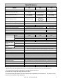
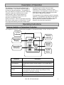
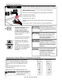
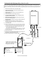
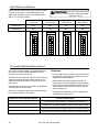
Direct Vent Tankless Water Heater
Operation and Installation Manual
Models:
305
505
705
FOR INDOOR APPLICATIONS ONLY
Models 305 and 505 are Energy Star Qualified
Table of Contents .................... 2
Consumer Safety Information .. 4
Operating Instructions.............. 5
Maintenance ............................ 8
Error Codes ............................. 9
Installation Instructions ............ 13
Warranty .................................. 38
INSTALLER: Leave this manual with the appliance.
CONSUMER: Retain this manual for future reference.
WARNING: If the information in these instructions is not
followed exactly, a fire or explosion may result causing
property damage, personal injury or death.
— Do not store or use gasoline or other flammable vapors and
liquids in the vicinity of this or any other appliance.
— WHAT TO DO IF YOU SMELL GAS
•
•
•
•
ANS Z21.10.3
●
CSA 4.3
Do not try to light any appliance.
Do not touch any electrical switch; do not use any phone in
your building.
Immediately call your gas supplier from a neighbor’s phone.
Follow the gas supplier’s instructions.
If you cannot reach your gas supplier, call the fire
department.
— Installation and service must be performed by a qualified
installer, service agency or the gas supplier.
Table of Contents
Specifications ..................................................... 3
Consumer Safety Information
Safety Definitions ............................................. 4
Safety Behaviors and Practices....................... 4
Safety Features ............................................... 4
Description of Operation ................................... 5
Operating Instructions
Features Available on Temperature
Controllers ....................................................... 5
Setting the Temperature .................................. 6
Temperature Options Without
a Temperature Controller ................................ 6
Temperature Ranges ....................................... 7
Setting Controller to Mute ................................ 7
Maintenance
Cleaning ...................................................... 8
Vent System ................................................ 8
Motors ......................................................... 8
Temperature Controller ............................... 8
Lime / Scale Build-up .................................. 8
Snow Accumulation..................................... 8
Visual Inspection of Flame .......................... 8
Error Codes
Error Code Table ....................................... 9, 10
Trouble Shooting for Common Issues ........... 11
Accessing Operating Information .................. 11
Water Quality ................................................. 11
Flushing the Heat Exchanger ........................ 12
(Error Code: LC or 00)
Installation Instructions ................................... 13
General Instructions ...................................... 13
Clearances from Appliance ........................... 14
Attachment of the Water Heater .................... 14
Electrical Connection ..................................... 15
Gas Piping
General Instructions ................................ 15
Pipe Sizing Procedure - Example ........... 16
Water Piping
General Instructions ................................ 17
Pressure Relief Valve .............................. 17
Freeze Protection .................................... 17
Freeze Protection Piping ............................... 18
Recommended Piping for Basic Installation .. 19
Recommended Piping for
Circulation Systems ....................................... 20
Optional Piping for Circulation Systems ........ 21
Venting Instructions
Intake / Exhaust Guidelines .................... 22
Condensate ............................................. 22
Maximum Vent Length ............................ 23
Venting Products ........................................... 24
Flue Terminal Clearances
(ANS Z21.10.3 ● CSA 4.3) ............................ 25
Additional Clearances - Vent Terminal .......... 26
Flue Installation for 305 and 505 Models...... 27
Flue Installation for 705 Model ................ 28, 29
High Altitude Installation ................................ 30
Connecting Multiple Water Heaters ............... 30
Temperature Controller Installation
Location ................................................... 31
Configurations ......................................... 31
Cable Lengths and Size .......................... 31
Mounting the Controller ........................... 32
Operating Instructions ................................... 33
Technical Data
Pressure Drop Curve ..................................... 34
Outlet Flow Data ............................................ 34
Space Heating ............................................... 35
Dimensions .................................................... 36
Ladder Diagram ............................................. 37
Warranty ...................................................... 38, 39
2
305, 505, 705 Indoor Manual
Specifications
Model
305
505
Minimum Gas Consumption Btu/h
Maximum Gas Consumption Btu/h
Hot water capacity (Min - Max) *
Hot water capacity (45°F rise)
15,000
19,000
180,000
199,000 Natural Gas
190,000 Propane Gas
237,000
0.6 - 7.5 GPM
(2.3 - 28.4 L/min)
0.6 - 9.4 GPM
(2.3 - 35.5 L/min)
0.6 - 9.8 GPM
(2.3 - 37 L/min)
6.6 GPM (25.0 L/min)
7.4 GPM (28.0 L/min)
Natural Gas
7.1 GPM (26.9 L/min)
Propane Gas
8.8 GPM (33.5 L/min)
Default Temperature Setting (no controller)
120º F (49º C)
Temperature Controller Default Setting
104º F (40º C)
Maximum Temp Setting (Commercial) **
Maximum Temp Setting (Residential)
160º F (71º C)
185º F (85º C)
Selectable at 120º F (49º C) or at 140º F (60º C)
Minimum Temperature Setting
50 lb (23 kg)
55 lb (25 kg)
Efficiency Rating
84%
Noise level
49 dB
Normal
65 W
79 W
Standby
By-Pass Control
100 W
116 W
Fixed
Electronic
Minimum Gas Supply
Pressure
Natural Gas
5.0 inch W.C.
Propane
8.0 inch W.C.
Maximum Gas Supply
Pressure
Natural Gas
10.5 inch W.C.
Propane
13.5 inch W.C.
Type of Appliance
Operation
Approved Gas Type
Connections
Direct Vent, Temperature controlled continuous flow gas hot water system.
With or without temperature controls, mounted in kitchen, bathroom, etc.
Natural Gas or Propane - Ensure unit matches gas type it's being installed on.
Gas Supply: 3/4" MNPT, Cold Water Inlet: 3/4" MNPT, Hot Water Outlet: 3/4" MNPT
Ignition System
Electric Connections
Direct Electronic Ignition
Appliance: AC 120 Volts, 60Hz. Temperature Control: DC 12 Volts (Digital)
Water Temperature Control
Water Supply Pressure
99 W
2W
Anti-frost Protection
Simulation Feedforward and Feedback.
Minimum Water Pressure: 20 PSI (Recommended 30-80 PSI for maximum performance)
Maximum Water Supply Pressure
150 PSI
Temperature Control Cable
Energy Star Qualified
140º F (60º C)
98º F (37º C)
Weight
Electrical Consumption
705
Non-Polarized Two Core Cable (Minimum 22 AWG)
Yes
Yes
No
* Minimum flow may vary slightly depending on the temperature setting and the inlet water temperature.
** for commercial and hydronic applications requiring higher temperatures
Specifications are subject to change without prior notice.
The maximum inlet gas pressure must not exceed the value specified by the manufacturer. The minimum value
listed is for the purpose of input adjustment.
305, 505, 705 Indoor Manual
3
Consumer Safety Information
Safety Definitions
This is the safety alert symbol. This symbol alerts you to potential hazards that can kill or hurt you and
others.
DANGER
Indicates an imminently hazardous situation which, if not avoided, will result in death or
serious injury.
WARNING
Indicates a potentially hazardous situation which, if not avoided, could result in death or
serious injury.
CAUTION
Indicates a potentially hazardous situation which, if not avoided, could result in minor or
moderate injury. It may also be used to alert against unsafe practices.
Safety Behavior and Practices
WARNING
• Keep the area around the appliance clear and free
from combustible materials, gasoline, and other
flammable vapors and liquids.
• Do not use this appliance if any part has been under
water. Immediately call a qualified service
technician to inspect the appliance and to replace
any part of the control system and any gas control
which has been under water.
• This appliance is equipped with a three-prong plug
for your protection against shock hazard and should
be plugged directly into a properly grounded threeprong receptacle. Do not cut or remove the ground
prong from this plug.
• Any alteration to the appliance or its controls can be
dangerous and will void the warranty.
• Always check the water temperature before entering
a shower or bath.
Safety Features
• Overheat: The appliance will automatically shut
down when the appliance exceeds a predetermined
temperature.
• Power Surge Fuse: A glass fuse protects against
overcurrent. If the fuse blows then all indicator
lamps will be off.
• Flame Failure: The appliance will automatically
shut down if the burner flame is extinguished.
• Fusible Link: In case the overheat feature does
not prevent the temperature from rising then the
fusible link will break shutting off the appliance.
• Power Failure: The appliance will cut off the gas if
it loses electrical power.
4
305, 505, 705 Indoor Manual
Description of Operation
This appliance is one of the most advanced water
heaters available. It provides a continuous supply of
hot water at a preset temperature. This appliance is
direct vent where air is brought in from the outside and
combustion gases are exhausted to the outside.
While electricity, water, and gas supplies are
connected, this appliance produces hot water
whenever a hot water tap is open.
Ignition is electronic. There is no pilot light consuming
gas while the water heater is not being used. The gas
burner lights automatically when the hot water tap is
opened and goes out when the tap is closed.
Installation of the temperature controller is highly
recommended. The temperature controller can set the
temperature within a specific range and can provide
error codes to diagnose any problems.
The temperature of the outgoing hot water is constantly
monitored. This appliance may adjust the water flow in
order to maintain the temperature setting. The water
flow may vary from summer to winter due to the
difference in ground water temperature.
Operating Instructions
Features Available on Temperature Controllers
The temperature controller is supplied with the appliance. Dimensions (inches): 3.5 W x 4.75 H x 0.75 D
In Use
Indicator
Priority
Indicator
Temperature
Display
Priority
Button
Temperature
Selection
On/Off
Button
Features
Description
Error Codes
When a fault is detected an error code flashes at the temperature
In Use Indicator
Indicates that hot water is being supplied (i.e. a hot water tap is
open).
On/Off Button
Used to turn the water heater On or Off.
Priority Button /
Indicator
Indicates that this controller is setting the temperature . Priority
can be switched to another controller by pressing its Priority
Button when no hot water is running.
Temperature Display
Shows the temperature setting.
Thermostat
Increases or decreases the temperature setting.
305, 505, 705 Indoor Manual
5
Setting the Temperature
DANGER
Hot water can be dangerous, especially for infants or children, the elderly,
or infirm. There is hot water scald potential if the thermostat is set too high.
Water temperatures over 125º F (51º C) can cause severe burns or
scalding resulting in death.
Hot water can cause first degree burns with exposure for as little as:
3 seconds at 140º F (60º C)
20 seconds at 130º F (54º C)
8 minutes at 120º F (48º C)
Test the temperature of the water before placing a child in the bath or
shower.
Do not leave a child or an infirm person in the bath unsupervised.
1. Press the “Priority button” on the
temperature controller. The
green Priority light will glow
indicating that this controller is
controlling the temperature and
that the water heater is ready to
supply hot water.
NOTICE
While any hot water is being
provided, the temperature setting can
only be adjusted between 98º F and
110º F.
NOTICE
Check local codes for the maximum
water temperature setting allowed
when used in nursing homes,
schools, day care centers, and all
other public applications.
NOTICE
If a newly installed unit with a
temperature controller has not been
powered for at least 6 hours then the
temperature will return to the default
setting of 104º F (40º C) if power is
interrupted.
NOTICE
There may be a variation between
the temperature displayed on the
temperature controller and the
temperature at the tap due to
weather conditions or the length of
pipe to the water heater.
The priority can only be changed
while no hot water is running.
2. Press the ▲ or ▼ buttons to
obtain the desired temperature
setting.
All hot water sources are able to
provide water at this temperature
setting until it is changed again at
this or another temperature
controller.
Temperature Options Without a Temperature Controller
The default temperature setting for this appliance
installed without a temperature controller is 120º F
(49º C). If desired the temperature setting can be
changed to 140º F (60º C) by adjustment of a dip
switch.
120º F (49º C)
140º F (60º C)
Switch No.
Switch No.
Set dip switch 5 to ON to obtain 140º F water
temperature setting.
Set dip switch 5 to OFF (default) to obtain 120º F
WARNING
6
DO NOT adjust the other dip
switches unless specifically
instructed to do so.
305, 505, 705 Indoor Manual
ON
O
F
F
ON
1
2
3
O
F
F
1
2
3
4
4
5
6
5
6
7
7
8
8
Temperature Ranges
This water heater will attempt to provide hot water at the temperature setting even when the water flow is varied
or when more than 1 tap is in use. The water heater can deliver water at only one temperature setting at a time.
The available temperatures for a given model are provided below.
Model
Temperature Settings Available (ºF)
305
98
100 102 104 106 108 110 115 120
125 130 135 140 150 160
*
*
*
*
**
**
505
98
100 102 104 106 108 110 115 120
125 130 135 140 150 160 185
*
*
*
*
**
**
**
705
98
100 102 104 106 108 110 115 120 125 130 135 140
150 160 185
**
**
**
Temp in Celsius ºC
37
38
66
39
40
41
42
43
46
49
52
54
57
60
71
85
* Re-setting the Maximum Temperature
Models 305 and 505 have a default maximum temperature of 120º F (49º C) and an option to increase the
maximum temperature to 140 ºF (60 ºC). Temperature settings from 125-140 ºF (52-60 ºC) are available by
setting dip switch 6 to ON in the SW1 bank of 8 dip switches.
Model 705 has a default maximum temperature of 140 ºF (60 ºC).
** Commercial Controller
These settings require the commercial controller which is for commercial and hydronic applications requiring
higher temperatures. When the commercial controller is connected, these higher temperatures are available
on all controller models in the system.
The commercial controller is intended for commercial and hydronic applications only. If commercial controller
is used in a residential dwelling for a hydronics application, a mixing valve must also be installed to limit the
potable hot water temperature to a safe temperature. Water temperatures over 125º F (51º C) can cause
severe burns or scalding. Refer to the Danger Alert on water temperatures. The manufacturer shall not, in
any event, be liable for damages resulting from such misuse or misapplication.
Suggested temperatures are
These temperatures are suggestions only.
•
•
A temperature lower than 98º F (37º C) can be
obtained at the tap by mixing with cold water.
Kitchen
Shower
120 ºF (49º C)
98º - 110º F (37º - 43º C)
To change the temperature scale from Celsius to Fahrenheit or vice versa, press and hold the “On/Off” button for
5 seconds while the water heater is OFF.
Setting Controller to Mute
To eliminate the beeps when keys are pressed or to turn the beeps back on, press and hold both the ▲and ▼
buttons until a beep is heard (approximately 5 seconds).
305, 505, 705 Indoor Manual
7
Maintenance
Snow Accumulation
WARNING
Turn off the electrical power supply, the manual gas
valve and the manual water control valve whenever
servicing the unit.
Repairs and maintenance should be performed by a
qualified service technician. The appliance should be
inspected annually by a qualified service technician.
Verify proper operation after servicing.
Cleaning
It is imperative that control compartments, burners,
and circulating air passageways of the appliance be
kept clean.
Keep the area around flue terminal free of snow and
ice. The appliance will not function properly if the
intake air or exhaust is impeded (blocked or partially
blocked) by obstructions.
Visual Inspection of Flame
The burner must flame evenly over the entire surface
when operating correctly. The flame must burn with a
clear, blue, stable flame. See the parts breakdown of
the burner for the location of the view ports.
The flame pattern should be as shown in the figures
below.
Clean as follows:
1. Turn off and disconnect electrical power. Allow to
cool.
2. Remove and clean the water inlet filter.
3. Remove the front panel by removing 4 screws.
4. Use pressurized air to remove dust from the main
burner, heat exchanger, and fan blades. Do not
use a wet cloth or spray cleaners on the burner.
Do not use volatile substances such as benzene
and thinners. They may ignite or fade the paint.
5. Use soft dry cloth to wipe cabinet.
Vent System
The vent system should be inspected at least annually
for blockages or damage.
Motors
Motors are permanently lubricated and do not need
periodic lubrication. Keep fan and motor free of dust
and dirt by cleaning annually.
Temperature Controller
Use a soft damp cloth to clean the temperature
controller. Do not use solvents.
Lime / Scale Build-up
If you receive Error Code “LC”, refer to the procedure,
Flushing the Heat Exchanger. Refer to the section on
Water Quality to see if your water needs to be treated
or conditioned. (When checking maintenance code
history, “00” is substituted for “LC”.)
8
305, 505, 705 Indoor Manual
Error Codes
This appliance has the ability to check its own operation continuously. If a fault occurs, an error code will flash on
the Display of the temperature controller. This assists with diagnosing the fault and may enable you to overcome
a problem without a service call. Please identify the code displayed when inquiring about service.
WARNING
Some of the checks below may need to be done by a qualified service technician. Call a
service technician for any remedy that involves gas or electricity. Call a service
technician if you have any doubt or reservation about performing the remedy yourself.
Error Code Table
Code
Fault
Remedy
02
No burner operation during
freeze protection mode
Service Call
10
Air Supply or Exhaust
Blockage
Ensure approved venting materials are being used.
Check that nothing is blocking the flue inlet or exhaust.
Check all vent components for proper connections.
Ensure vent length is within limits.
Ensure condensation collar was installed correctly.
Verify dip switches are set properly.
Check fan for blockage.
11
No Ignition
Check that the gas is turned on at the water heater, gas meter, or cylinder.
Ensure gas type and pressure is correct.
Ensure gas line, meter, and/or regulator is sized properly.
Bleed all air from gas lines.
Verify dip switches are set properly.
Ensure appliance is properly grounded.
Disconnect all 2-Unit or Multi-Unit connections to isolate the problem.
Ensure igniter is operational.
Check igniter wiring harness for damage.
Check gas solenoid valves for open or short circuits.
Remove burner cover and ensure all burners are properly seated.
Remove burner plate and inspect burner surface for condensation or debris.
12
Flame Failure
Check that the gas is turned on at the water heater and gas meter. Check for
obstructions in the flue outlet.
Ensure gas line, meter, and/or regulator is sized properly.
Ensure gas type and pressure is correct.
Bleed all air from gas lines.
Ensure proper venting material was installed.
Ensure condensation collar was installed properly.
Ensure vent length is within limits.
Verify dip switches are set properly.
Ensure appliance is properly grounded.
Disconnect keypad.
Disconnect all 2-Unit or Multi-Unit connections to isolate the problem.
Check power supply for loose connections.
Check power supply for proper voltage and voltage drops.
Ensure flame rod wire is connected.
Check flame rod for carbon build-up.
Disconnect and reconnect all wiring harnesses on unit and PC board.
Check all components for electrical short.
Check gas solenoid valves for open or short circuits.
Remove burner plate and inspect burner surface for condensation or debris.
305, 505, 705 Indoor Manual
9
Error Code Table
Code
Fault
Remedy
14
Thermal Fuse
16
Over Temperature
Warning
32
Outgoing Water
Temperature Sensor
Fault
33
Heat Exchanger
Outgoing Temperature
Sensor Fault
34
Combustion Air
Temperature Sensor
Fault
52
Modulating Solenoid
Valve Signal Abnormal
Combustion Fan
Failure
Check gas type of unit and ensure it matches gas type being used.
Check for restrictions in air flow around unit and vent terminal.
Check for low water flow in a circulating system causing short-cycling.
Ensure dip switches are set to the proper position.
Check for foreign materials in combustion chamber and/or exhaust piping.
Check heat exchanger for cracks and/or separations.
Check heat exchanger surface for hot spots which indicate blockage due to scale buildup. Refer to instructions in manual for flushing heat exchanger.
Measure resistance of safety circuit.
Ensure high fire and low fire manifold pressure is correct.
Check for improper conversion of product.
Check for restrictions in air flow around unit and vent terminal.
Check for low water flow in a circulating system causing short-cycling.
Check for foreign materials in combustion chamber and/or exhaust piping.
Check for clogged heat exchanger.
Check sensor wiring for damage.
Measure resistance of sensor.
Clean sensor of scale build-up.
Replace sensor.
Check sensor wiring for damage.
Measure resistance of sensor.
Clean sensor of scale build-up.
Replace sensor.
Check for restrictions in air flow around unit and vent terminal.
Check sensor wiring for damage.
Measure resistance of sensor.
Clean sensor of scale build-up.
Ensure fan blade is tight on motor shaft and is in good condition.
Replace sensor.
Check modulating gas solenoid valve wiring harness for loose or damaged terminals.
Measure resistance of valve coil.
Ensure fan will turn freely.
Check wiring harness to motor for damaged and/or loose connections.
Measure resistance of motor winding.
Check wiring harness to all solenoids for damage and/or loose connections.
Measure resistance of each solenoid valve coil.
61
71
72
LC
No
code
10
SV0, SV1, SV2, and
SV3 Solenoid Valve
Circuit Fault
Flame Sensing Device
Fault
Scale Build-up in Heat
Exchanger (when
checking maintenance
code history, “00” is
substituted for “LC”)
Nothing happens when
water flow is activated.
Ensure flame rod is touching flame when unit fires.
Check all wiring to flame rod for damage.
Remove flame rod and check for carbon build-up; clean with sand paper.
Check inside burner chamber for any foreign material blocking flame at flame rod.
Measure micro amp output of sensor circuit with flame present.
Replace flame rod.
Flush heat exchanger. Refer to instructions in manual.
Replace heat exchanger.
Clean inlet water supply filter.
On new installations ensure hot and cold water lines are not reversed.
Check for bleed over. Isolate unit from building by turning off hot water line to building.
Isolate the circulating system if present. Open your pressure relief valve; if water is
flowing, there is bleed over in your plumbing.
Ensure you have at least the minimum flow rate required to fire unit.
Ensure turbine spins freely.
Measure the resistance of the water flow control sensor.
Check for DC shorts at components.
305, 505, 705 Indoor Manual
Trouble Shooting for Common Issues
I don’t have any hot water when I open the tap.
Make sure there is gas, water, and electricity to the
water heater (power is turned on and the gas is turned
on).
When I was using the hot water, the water got cold.
If you adjusted the flow from the tap to lessen it, you
may have gone below the minimum flow required. This
water heater requires a minimum flow rate to operate.
(See the specification page for the flow rate of your
model.) Decrease the temperature setting at the
temperature controller or increase the water flow.
White smoke comes out of the exhaust.
During colder weather when the exhaust temperature
is much hotter than the outside air, the exhaust fumes
condense producing water vapor.
When I open a hot tap, I do not immediately get hot
water.
Hot water must travel through your plumbing from the
water heater to the faucet. The time period for hot
water to reach your fixture is determined by the amount
of water in the plumbing system between the water
heater and the fixture, water pressure, and the flow
rate of the fixture.
After I turn off the hot water tap, the fan on the
water heater continues to run.
The fan is designed to continue running for a short time
after the flow of water stops. This is to ensure constant
water temperatures during rapid starting and stopping,
as well as exhausting any residual gas flue products
from the unit.
Accessing Operating Information
To display the most recent error codes press and hold the “On/Off” button for 2 seconds. While holding the “On/
Off” button press the ▲ button. The last 9 error codes will flash one after the other. To exit this mode press the
“On/Off” and ▲ button as before.
To display the water flow through the water heater press and hold the ▲ button for 2 seconds and without
releasing the ▲ button press the “On/Off” button.
To display the outlet water temperature press and hold the ▼ button for 2 seconds and without releasing the ▼
button press the “On/Off” button.
Water Quality
Consideration of care for your water heater should
include evaluation of water quality. If the water quality
exceeds the target levels provided in the table, you
may want to treat or condition the water.
Total Hardness
Up to 200 mg / L
Aluminum *
Up to 0.2 mg / L
* Source: Part 143 National Secondary Drinking Water
Regulations
Chlorides *
Up to 250 mg / L
Copper *
Up to 1.0 mg / L
Iron *
Up to 0.3 mg / L
Manganese *
Up to 0.05 mg / L
Maximum Level
pH *
TDS (Total Dissolved
Solids) *
Zinc *
305, 505, 705 Indoor Manual
6.5 to 8.5
Up to 500 mg / L
Up to 5 mg / L
11
Flushing the Heat Exchanger (Error Code: LC or 00)
An “LC” or “00” error code indicates the unit is beginning to lime up and must be flushed. Failure to flush the
appliance will cause damage to the heat exchanger. Damage caused by lime build-up is not covered by the unit’s
warranty. After flushing, reset the LC fault code by turning off the power to the unit and turning the power back
on.
1.
2.
3.
4.
5.
6.
7.
8.
9.
10.
11.
12.
13.
Disconnect electrical power to the water heater.
Close the shutoff valves on both the hot water and cold
water lines (V3 and V4).
Connect pump outlet hose (H1) to the cold water line at
service valve V2.
Connect drain hose (H3) to service valve V1.
Pour approximately 4 gallons of virgin, food grade, white
vinegar or citric acid into pail.
Place the drain hose (H3) and the hose (H2) to the pump
inlet into the cleaning solution.
Open both service valves (V1 and V2) on the hot water and
cold water lines.
Operate the pump and allow the cleaning solution to
circulate through the water heater for at least 45 minutes.
Turn off the pump.
Rinse the cleaning solution from the water heater as follows:
a. Remove the free end of the drain hose (H3) from the pail.
b. Close service valve, (V2), and open shutoff valve, (V4).
Do not open shutoff valve, (V3).
c. Allow water to flow through the water heater for 5 minutes
d. Close service valve, (V1), and open shutoff valve, (V3).
Disconnect all hoses.
Remove the in-line filter at the cold water inlet and clean out
any residue. Place filter back into unit.
Restore electrical power to the water heater.
Water Heater
In-line
Filter
V2
V1
H3
V4
V3
Cold Water Line
Hot Water Line
H2
H1
5 gallon pail of virgin, food
grade, white vinegar (or virgin,
food grade, citric acid).
Circulating Pump
KEY
Pressure Regulator
3/4" Ball Valve
Circulating Pump
3/4" Union
Check Valve
Pressure Relief Valve
12
Boiler Drain Valve
S
Solenoid Valve
305, 505, 705 Indoor Manual
Gas Supply
Installation Instructions
Only properly trained and qualified installers should
install this appliance. The warranty may be voided due
to improper installation or installation by a non-qualified
installer.
It is highly recommended that all installers attend a
product knowledge class.
General Instructions
• Follow the installation instructions and those in Care
and Maintenance for adequate combustion and
ventilation air.
WARNING
Do not use substitute materials.
Use only parts certified with the appliance.
• This appliance must be installed by a state qualified
or licensed contractor. It is the responsibility of the
person having the water heater installed to ensure
the installing contractor has proper licenses and
permits for installing water heaters in your location.
It is highly recommended that installers attend a
product knowledge class to ensure customer
satisfaction and warranty coverage. Failure to
comply with state and local codes pertaining to
water heater installations may void the warranty.
• This appliance is not to be installed outdoors.
• A qualified installer or service technician should
install the appliance, inspect it, and leak test it
before use.
• The installation must conform with local codes or, in
the absence of local codes, with the National Fuel
Gas Code, ANSI Z223.1/NFPA 54, or the Natural
Gas and Propane Installation Code, CSA B149.1.
• The appliance, when installed, must be electrically
grounded in accordance with local codes or, in the
absence of local codes, with the National Electrical
Code, ANSI/NFPA 70, or the Canadian Electrical
Code, CSA C22.1.
• The appliance and its appliance main gas valve
must be disconnected from the gas supply piping
system during any pressure testing of that system at
test pressures in excess of 1/2 psi (3.5 kPa) (13.84
in W.C.).
• The appliance should be located in an area where
water leakage of the unit or connections will not
result in damage to the area adjacent to the
appliance or to lower floors of the structure. When
such locations cannot be avoided, it is
recommended that a suitable drain pan, adequately
drained, be installed under the appliance. The pan
must not restrict combustion air flow.
• The flow of combustion and ventilation air shall not
be obstructed.
• This appliance is not suitable for use in an
application such as a pool or spa heater that uses
chemically treated water . (This appliance is
suitable for filling large or whirlpool bath tubs with
potable water.)
• If a water heater is installed in a closed water supply
system, such as one having a backflow preventer in
the cold water supply line, means shall be provided
to control thermal expansion. Contact the water
supplier or local plumbing inspector on how to
control thermal expansion.
• Should overheating occur or the gas supply fail to
shut off, turn off the manual gas control valve to the
appliance.
• Keep the air intake location free of chemicals such
as chlorine or bleach that produce fumes. These
fumes can damage components and reduce the life
of your appliance.
• The appliance must be isolated from the gas supply
piping system by closing its individual manual
shutoff valve during any pressure testing of the gas
supply piping system at test pressures equal to or
less than 1/2 psi (3.5 kPa) (13.84 in W.C.).
305, 505, 705 Indoor Manual
13
Clearances from Appliance
to Combustibles
305
505
305
505
705
Top of
Heater
6 inches
(152 mm)
12 inches
(305 mm)
2 inches
(51 mm)
2 inches
(51 mm)
Back of
Heater
0 (zero)
0 (zero)
0 (zero)
0 (zero)
Front of
Heater
6 inches
(152 mm)
24 inches
(610 mm)
6 inches
(152 mm)
24 inches
(610 mm)
Sides of
Heater
2 inches
(51 mm)
2 inches
(51 mm)
1/2 inch
(13 mm)
1/2 inch
(13 mm)
Floor/
Ground
12 inches
(305 mm)
12 inches
(305 mm)
12 inches
(305 mm)
2 inches
(51 mm)
Vent
0 (zero)
to top
to NonCombustibles
4 inches * 0 (zero)
705
0 (zero)
to side
to floor/ground
to front
* 4 inches (102 mm) for enclosed area; 1 inch (26 mm) for unenclosed area.
The clearance for servicing is 24 inches in front of the water heater.
For closet installation: 305, 505: clearance is 6 inches (152 mm) from the front.
705: clearance is 24 inches (610 mm) from the front.
Attachment of the Water Heater
1. Identify the installation location and confirm that
the installation will meet all required clearances.
2. Securely attach the water heater to the wall using
any of the holes in the wall installation brackets
which are at the top and bottom of the water
heater. Ensure that the attachment strength is
sufficient to support the weight. Refer to the
weight of the water heater in the Specifications
section.
14
305, 505, 705 Indoor Manual
wall installation
brackets
Electrical Connection
The water heater requires a standard 3 prong 120 VAC, 60 Hz properly grounded wall outlet. Plug the 6ft long
power cord into the wall outlet.
Gas Piping
General Instructions
• A manual gas control valve must be placed in the
gas supply line to the water heater. A union can be
used on the connection above the shut off valve for
the future servicing or disconnection of the unit.
• Check the type of gas and the gas inlet pressure
before connecting the water heater. If the water
heater is not of the gas type that the building is
supplied with, DO NOT connect the water heater.
Contact the dealer for the proper unit to match the
gas type.
• Check the gas supply pressure immediately
upstream at a location provided by the gas
company. Supplied gas pressure must be within the
limits shown in the Specifications section.
• Before placing the appliance in operation all joints
including the heater must be checked for gas
tightness by means of leak detector solution, soap
and water, or an equivalent nonflammable solution,
as applicable. (Since some leak test solutions,
including soap and water, may cause corrosion or
stress cracking, the piping shall be rinsed with water
after testing, unless it has been determined that the
leak test solution is non-corrosive.)
• Always use approved connectors to connect the unit
to the gas line. Always purge the gas line of any
debris before connection to the water heater.
• The gas supply line shall be gas tight, sized, and so
installed as to provide a supply of gas sufficient to
meet the maximum demand of the heater and all
other gas consuming appliances at the location
without loss of pressure.
• Any compound used on the threaded joint of the gas
piping shall be a type which resists the action of
liquefied petroleum gas (propane / LPG).
• Refer to an approved pipe sizing chart if in doubt
about the size of the gas line.
305, 505, 705 Indoor Manual
15
Gas Piping
Pipe Sizing Procedure - Example
The gas supply must be capable of handling the entire gas load at the location. Gas line sizing is based on gas
type, the pressure drop in the system, the gas pressure supplied, and gas line type. Refer to the National Fuel
Gas Code, NFPA 54, for proper gas line sizing. The below information is provided as an example.
1. Determine the cubic feet per hour of gas required by dividing the gas input (on the rating plate) by the heating
value of the gas (available from the local gas company). The gas input needs to include all gas products at
the location and the maximum BTU usage at full load when all gas products are in use.
Gas Input of the water heater (BTU / HR)
Cubic Feet per Hour (CFH) =
Heating Value of Gas (BTU / FT 3 )
2. Use the table for your gas type to find the pipe size required for your cubic feet per hour of gas and your pipe
length.
Example: The heating value of propane gas for your location is 2516 BTU / FT 3.
The gas input is 190,000 BTU/HR. Additional appliances at the location require 75,000 BTU/HR.
Therefore the cubic feet per hour = (190,000+75,000) / 2516 = 105.3 FT 3/ HR.
If the pipe length is 100 ft then the 3/4 inch pipe size capable of supplying 197 FT 3/ HR of propane gas
will be adequate.
Pipe Sizing Table - Natural Gas
cubic feet per hour
Pipe Sizing Table - Propane Gas
Schedule 40 Metallic Pipe
Inlet Pressure: less than 2 psi (55 inches W.C.)
Pressure Drop: 0.3 inches W.C.
Specific Gravity: 0.60
Length
16
Pipe Size (inches)
3/4
1
1 1/4
1 1/2
10
273
514
1060
1580
20
188
353
726
30
151
284
40
129
50
cubic feet per hour
Schedule 40 Metallic Pipe
Inlet Pressure: 11.0 inches W.C.
Pressure Drop: 0.5 inches W.C.
Specific Gravity: 1.50
Length
Pipe Size (inches)
1/2
3/4
1
1 1/4
10
291
608
1150
2350
1090
20
200
418
787
1620
583
873
30
160
336
632
1300
243
499
747
40
137
287
541
1110
114
215
442
662
50
122
255
480
985
60
104
195
400
600
60
110
231
434
892
70
95
179
368
552
80
101
212
400
821
80
89
167
343
514
100
94
197
372
763
90
83
157
322
482
125
89
185
349
716
100
79
148
304
455
150
84
175
330
677
125
70
131
269
403
175
74
155
292
600
150
63
119
244
366
200
67
140
265
543
175
58
109
224
336
200
54
102
209
313
305, 505, 705 Indoor Manual
Water Piping
General Instructions
• A manual water control valve must be placed in the
water inlet connection to the water heater before it is
connected to the water line. Unions may be used
on both the hot and cold water lines for future
servicing and disconnection of the unit.
• The piping (including soldering materials) and
components connected to this appliance must be
approved for use in potable water systems.
• Purge the water line to remove all debris and air.
Debris will damage the water heater.
• Toxic chemicals such as those used for boiler water
treatment are not to be introduced to the potable
water used for space heating.
• If the appliance will be used as a potable water
source, it must not be connected to a system that
was previously used with a nonpotable water
heating appliance.
• Ensure that the water filter on the water heater is
clean and installed.
Pressure Relief Valve
• An approved pressure relief valve is required by the
American National Standard (ANSI Z21.10.3) /
Canadian Standard (CSA 4.3) for all water heating
systems.
• The relief valve must comply with the standard for
Relief Valves and Automatic Gas Shutoff Devices
for Hot Water Supply Systems ANSI Z21.22 and /or
the standard Temperature, Pressure, Temperature
and Pressure Relief Valves and Vacuum Relief
Valves, CAN1-4.4.
• The relief valve must be rated up to 150 psi and to
at least the maximum BTU/hr of the appliance.
• The discharge from the pressure relief valve should
be piped to the ground or into a drain system to
prevent exposure or possible burn hazards to
humans or other plant or animal life. Follow local
codes. Water discharged from the relief valve could
cause severe burns instantly, scalds, or death.
• The pressure relief valve must be manually
operated once a year to check for correct operation.
• The relief valve should be added to the hot water
outlet line according to the manufacturer’s
instructions. DO NOT place any other type valve or
shut off device between the relief valve and the
water heater.
• Do not plug the relief valve and do not install any
reducing fittings or other restrictions in the relief line.
The relief line should allow for complete drainage of
the valve and the line.
• If a relief valve discharges periodically, this may be
due to thermal expansion in a closed water supply
system. Contact the water supplier or local
plumbing inspector on how to correct this situation.
Do not plug the relief valve.
• Neither this water heater nor the American National
Standard (ANSI Z21.10.3) / Canadian Standard
(CSA 4.3) requires a combination temperature and
pressure relief valve for this appliance. However,
local codes may require a combination temperature
and pressure relief valve.
Freeze Protection
The freeze protection features include electrical
heating elements and intermittent firing of the burner.
Freeze protection may be disabled if electricity or gas
is not supplied, or if there is an error preventing the
water heater from functioning. Loss of freeze
protection may result in water damage from a burst
heat exchanger or water lines.
In addition, the solenoid valves should be connected
electrically to a surge protector with terminals that
attaches to the PC board in the unit. This allows the
solenoid valves to operate if the water heater is
disabled due to an error code.
The solenoid valves and the surge protector with
terminals are available for purchase separately.
The installation of auto drain down solenoid valves is
optional. However, it is strongly recommended that
these valves be installed to prevent damage from
freezing in case the normal freeze protection should
become disabled. Any product damage due to
freezing will not be covered by the warranty.
305, 505, 705 Indoor Manual
17
Freeze Protection Piping
Vacuum
Breaker
NOTICE
Warranty does not cover damage due to freezing.
When electrical power and gas are supplied to the
water heater, it will not freeze in environments as cold
as -30º F when protected from direct wind exposure.
Water Heater
In the event of a power failure at temperatures below
freezing the water heater should be drained of all
water to prevent freezing damage.
The unit may be drained manually. However, it is
highly recommended that drain down solenoid valves
be installed that will automatically drain the unit if
power is lost. It is also recommended that a surge
protector with terminals be installed that attaches to
the PC board in the unit and allows the solenoid
valves to operate if the unit is disabled due to an error
code.
When the electrical power to the water heater fails, the
3/4” solenoid valve closes (stopping the flow of water
into the heater) and the 1/2” solenoid valve opens
(allowing the water heater and associated piping to
drain. Ensure that you run the drain for the solenoids
to the outside environment to prevent discharging
water inside the building causing water damage).
3/4" Gas Connection
NOTE:
Heat trace ALL water pipe and fittings located
outside home (attic, crawl space) or building
structure. (ALL water pipe and fittings shown
above the dashed line in the drawing.)
Gas Supply
NOTE:
S
ALL pipe and fittings shown below dashed line
should be located inside home or building
structure.
Minimum 3/4" Hot Water
Supply Line
1/2" Minimum
Normally Open
Solenoid Valve
Minimum 3/4"
Cold Water
Supply Line
S
The vacuum breaker line should be located
inside the building structure.
3/4" Minimum
Normally Closed
Solenoid Valve
Route to Floor Drain
KEY
Pressure Regulator
3/4" Ball Valve
Circulating Pump
3/4" Union
Check Valve
Pressure Relief Valve
18
Boiler Drain Valve
S
Solenoid Valve
This is not an engineered drawing. It is intended only as a guide and not
as a replacement for professionally engineered project drawings. This
drawing is not intended to describe a complete system. It is up to the
contractor/engineer to determine the necessary components and
configuration of the particular system being installed. This drawing does
not imply compliance with local building code requirements. It is the
responsibility of the contractor/engineer to ensure installation is in
accordance with all local building codes. Confer with local building
officials before installation.
305, 505, 705 Indoor Manual
Recommended Piping for Basic Installation
Water Heater
Equipment List
QTY
Water Heaters
1
Plumbing Installation
1
Kit (Optional)
(3/4" Fittings Include:
2 Unions, 2 Ball Valves,
2 Drain Valves and
1 Pressure Relief Valve.)
3/4" Gas Connection
Gas Supply
3/4" Hot Water Supply Line
3/4" Cold Water Supply Line
For Building Fixtures
KEY
Pressure Regulator
3/4" Ball Valve
Circulating Pump
3/4" Union
Check Valve
Pressure Relief Valve
Boiler Drain Valve
S
Solenoid Valve
This is not an engineered drawing. It is intended only as a guide and not
as a replacement for professionally engineered project drawings. This
drawing is not intended to describe a complete system. It is up to the
contractor/engineer to determine the necessary components and
configuration of the particular system being installed. This drawing does
not imply compliance with local building code requirements. It is the
responsibility of the contractor/engineer to ensure installation is in
accordance with all local building codes. Confer with local building
officials before installation.
305, 505, 705 Indoor Manual
19
Recommended Piping for Circulation Systems
NOTE:
For residential and commercial
applications, this piping arrangement maintains full warranty.
Water Heater
Equipment List
QTY
Water Heaters
1
Plumbing Installation
1
Kit (Optional)
(3/4" Fittings Include:
2 Unions, 2 Ball Valves,
2 Drain Valves and
1 Pressure Relief Valve.)
For this application:
Pump should be controlled by an Aquastat, Timer or Combination Aquastat and
Timer.
3/4" Gas Connection
Pump to be sized to maintain circulation
loop temperature.
The pump should be sized to overcome
the pressure loss through the tank water
heater, and supply and return plumbing.
Gas Supply
Pump to be of bronze or stainless
construction.
Minimum 3/4" Cold Water Supply Line
Tank Water Heater to be Sized for
Heat Loss of Circulation Loop.
IMPORTANT: Connect the building
return line to the hot water supply line
as close as possible to the water
heater.
Building Supply
Electric Water
Heater
Building
Fixtures
Expansion Tank
KEY
Pressure Regulator
3/4" Ball Valve
Circulating Pump
3/4" Union
Check Valve
Pressure Relief Valve
20
Boiler Drain Valve
S
Solenoid Valve
This is not an engineered drawing. It is intended only as a guide and not
as a replacement for professionally engineered project drawings. This
drawing is not intended to describe a complete system. It is up to the
contractor/engineer to determine the necessary components and
configuration of the particular system being installed. This drawing does
not imply compliance with local building code requirements. It is the
responsibility of the contractor/engineer to ensure installation is in
accordance with all local building codes. Confer with local building
officials before installation.
305, 505, 705 Indoor Manual
Optional Piping for Circulation Systems
NOTE:
For residential and commercial
applications, this piping arrangement
reduces the warranty to the following:
3 years on heat exchanger
3 year on parts
Equipment List
Water Heater
Full warranty will be maintained if an
on-demand recirculation system in
incorporated. Refer to the Limited
Warranty.
QTY
Water Heaters
1
Plumbing Installation
1
Kit (Optional)
(3/4" Fittings Include:
2 Unions, 2 Ball Valves,
2 Drain Valves and
1 Pressure Relief Valve.)
For this application:
Pump should be controlled by an Aquastat,
Timer or Combination Aquastat and Timer.
Pump to be sized to maintain circulation
loop temperature.
A minimum of 3 GPM flow is recommended
for the circulation system.
The pump should be sized to overcome the
pressure loss through the water heate r,
supply and return plumbing.
Pump to be of bronze or stainless construc tion.
Note:
3/4" Gas Connection
Gas Supply
Water heater outlet temperature
cannot be adjusted when
circulation pump is running.
Minimum 3/4" Hot Water
Supply Line
Minimum 3/4 “ Cold Water Supply Line
(Optional)
2-6 Gallon
Storage Tank
(To eliminate cold water
sandwich effect caused by
frequent On/Off operation)
Expansion Tank
Building Fixture Outlets
KEY
Pressure Regulator
3/4" Ball Valve
Circulating Pump
3/4" Union
Check Valve
Pressure Relief Valve
Boiler Drain Valve
S
Solenoid Valve
This is not an engineered drawing. It is intended only as a guide and not
as a replacement for professionally engineered project drawings. This
drawing is not intended to describe a complete system. It is up to the
contractor/engineer to determine the necessary components and
configuration of the particular system being installed. This drawing does
not imply compliance with local building code requirements. It is the
responsibility of the contractor/engineer to ensure installation is in
accordance with all local building codes. Confer with local building
officials before installation.
305, 505, 705 Indoor Manual
21
Venting Instructions
Intake / Exhaust Guidelines
Refer to the specific instructions on your vent product for additional installation requirements.
•
This water heater is a direct vent water heater and
therefore is certified and listed with the vent
system. You must use vent components that are
certified and listed with the water heater model.
•
Do not combine vent components from different
manufacturers.
•
The vent system must vent directly to the outside
of the building and use outside air for combustion.
•
Venting should be as direct as possible with a
minimum number of pipe fittings.
•
Avoid dips or sags in horizontal vent runs by
installing supports per the vent manufacturer’s
instructions.
•
Support horizontal vent runs every four feet and all
vertical vent runs every six feet or in accordance
with local codes.
•
Vent diameter must not be reduced.
•
Do not connect the venting system with an existing
vent or chimney.
•
Do not common vent with the vent pipe of any
other water heater or appliance.
•
Vent connections must be firmly pressed together
so that the gaskets form an air tight seal.
•
On the 305 and 505 models, the vent piece
connected to the water heater must be secured
with one self-tapping screw.
•
Refer to the instructions of the vent system
manufacturer for component assembly instructions.
•
If the vent system is to be enclosed, it is suggested
that the design of the enclosure shall permit
inspection of the vent system. The design of such
enclosure shall be deemed acceptable by the
installer or the local inspector.
NOTICE
If it becomes necessary to access an enclosed vent
system for service or repairs, the manufacturer is not
responsible for any costs or difficulties in accessing
the vent system. Warranty does not cover obtaining
access to an enclosed vent system.
WARNING
Condensate
Condensate formation can occur in high efficiency
direct vent appliances. To prevent condensate
damage follow these instructions.
If the condensate collector is not used, the drain pipe
must be capped to prevent exhaust gases and
condensate from entering the building. The cap is
supplied on the appliance.
NOTICE
Provisions must be made to prevent the condensate
from entering the water heater. Without proper
drainage or disposal, condensate will damage the heat
exchanger.
• Vertical terminations must incorporate a condensate
drain and trap as close as possible to the appliance.
• This water heater has an integrated condensate
collector.
• Slope any horizontal venting 1/4 inch per foot (19
mm / m), towards the heater if the condensate
collector is used, or towards the exhaust terminal if
the condensate collector is not used.
• Regions of cold climate will create more condensate
in the vent system. The condensate collector
should be used in cold climates.
• Dispose of condensate per local codes.
• The condensate trap must contain a minimum of 3
inches (75 mm) of water.
22
305, 505, 705 Indoor Manual
Venting Instructions
Maximum Vent Length
1. Determine the number of 90 degree elbows in the vent system. (Two 45 degree elbows count as one 90
degree elbow.)
2. Refer to the table to find the maximum vent length based on the number of elbows.
3. Follow the applicable note.
Example: If you have one elbow then your maximum vent length is 35 feet (10.7 m). If your actual length is
greater than 15 ft (4.6 m) then move dip switch no. 1 (SW1) to OFF.
Number of 90° Elbows
0
1
2
3
4
5
6
41 ft 1
(12.5 m)
35 ft 2
(10.7 m)
29 ft 3
(8.8 m)
23 ft 4
(7.0 m)
17 ft 4
(5.2 m)
11 ft 4
(3.4 m)
5 ft 4
(1.5 m)
1 If the length is greater than 21 ft (6.4 m) then move
dip switch no. 1 (SW1) to OFF.
2 If the length is greater than 15 ft (4.6 m) then move
dip switch no. 1 (SW1) to OFF.
Switch No.
Notes 1234
ON
O
F
F
1
2
3
4
3 If the length is greater than 9 ft (2.7 m) then move
dip switch no. 1 (SW1) to OFF.
5
4 Move dip switch no. 1 (SW1) to OFF.
8
6
7
NOTICE
If you have a longer vent length, dip switch no. 1 is required to be in the OFF position. This ensures the water
heater will run properly. Blocked flue error codes and shutdowns may result if dip switch no. 1 is not in the
correct position. On the 505 model, the maximum water flow capacity will be reduced by about 10% when dip
switch no. 1 is OFF.
305, 505, 705 Indoor Manual
23
Venting Products
Listed and Tested Vent Products for the 305 and 505 Models
Manufacturer
Product
Parts
Ubbink
Rolux Vent System
Heat-Fab
Saf-T Vent SC system
Metal-Fab
Corr/Guard Vent/Air
Intake System
Refer to the manufacturer’s technical literature for
specific part numbers and instructions.
Listed and Tested Vent Products for the 705 Model
Vertical
Termination
Horizontal
Termination
Horizontal
Concentric
Termination
Adjustable
Horizontal
Concentric
Termination
Manufacturer
Product
Appliance
Adapter
Heat-Fab
Saf-T Vent
9401AMTK
5400CI
9492
NA
NA
Z-Flex
Z-Vent
2SVSNA04.5
2SVSRCF4
2SVSTPX4
NA
NA
ProTech
Systems
FasNSeal
FSAAU4 *
FSRC4 *
FSBS4 *
FSDVPTB04LH *
FSDVWT4
FSDVWMTP4LH,
FSEDVWMTP4LH
Metal-Fab
Corr/Guard
4CGOA
4CGSWC
4CGSWMCM
4CG7HT90
4CG7HT
NA
Vent Manufacturer Contact Information for Installation Instructions and Parts Lists:
Ubbink
Heat-Fab
Telephone: 866-677-4960
500 Tennessee Waltz Parkway
Ashland City, TN 37015
Telephone:
Fax:
E-mail:
Web Site:
Z-Flex
800-772-0739
413-863-4803
[email protected]
www.heatfab.com
Telephone:
Fax:
E-mail:
Web Site:
800-654-5600
888-889-3539
[email protected]
www.novaflex.com
ProTech Systems, Inc.
Metal-Fab Inc.
Telephone: 800-766-3473
518-463-7284
Fax:
518-463-5271
E-mail:
[email protected]
Web Site: www.protechinfo.com
Telephone: 800-835-2830
316-943-2351
Fax:
316-943-2717
E-mail:
[email protected]
Web Site: www.metal-fabinc.com
24
305, 505, 705 Indoor Manual
Flue Terminal Clearances (ANS Z21.10.3 ● CSA 4.3)
INSIDE
CORNERDETAIL
G
H
A
B
D
B
C
B
B
FIXED
CLOSED
J
B
A
OPERABLE
L
F
B
Description
Ref
2
∗
M
K
OPERABLE
E
1
I
FIXED
CLOSED
X
AIR SUPPLY INLET
V
VENT TERMINAL
AREA WHERE
TERMINAL IS NOT
PERMITTTED
US Installations
A
Clearance above grade, veranda, porch, deck, or balcony
12 inches (30 cm)
B
Clearance to window or door that may be opened
12 inches (30 cm)
C
Clearance to permanently closed window
*
D
Vertical clearance to ventilated soffit, located above the terminal
within a horizontal distance of 2 feet (61 cm) from the center line
of the terminal
*
E
Clearance to unventilated soffit
*
F
Clearance to outside corner
*
G
Clearance to inside corner
*
H
Clearance to each side of center line extended above meter/
regulator assembly
*
I
Clearance to service regulator vent outlet
*
J
Clearance to nonmechanical air supply inlet to building or the
combustion air inlet to any other appliance
K
Clearance to a mechanical air supply inlet
L
Clearance above paved sidewalk or paved driveway located on
public property
*
M
Clearance under veranda, porch, deck, or balcony
*
12 inches (30 cm)
3 feet (91 cm) above if within
10 feet (3 m) horizontally
A vent shall not terminate directly above a sidewalk or paved driveway that is located between two single family dwellings and serves
both dwellings.
Permitted only if veranda, porch, deck, or balcony is fully open on a minimum of two sides beneath the floor.
For clearances not specified in ANSI Z223.1/NFPA 54 or CSA B149.1, clearances are in accordance with local installation codes and the
requirements of the gas supplier.
305, 505, 705 Indoor Manual
25
Additional Clearances - Vent Terminal
Local codes supersede these clearances.
• Avoid termination locations near a dryer vent.
• Avoid termination locations near commercial cooking exhaust.
Vent terminal (represents concentric vent terminal for the water heater)
V
60"
(0.91 m) to ventilated
or unventilated soffit
36" or eve vent; or to a
deck or porch
(1.52 m) vertically
between water heater
terminals
V
12"
V
(0.30 m ) to an
inside corner
V
12"
24"
(0.30 m) between
water heater terminals
at same level
(0.61 m) to wall or parapet
V
INSIDE
CORNER
(1.52 m) between
water heater
terminals at
different levels
60"
V
V
12"
V
26
305, 505, 705 Indoor Manual
V
(0.30 m) between water
heater terminals at same
level
Flue Installation for the 305 and 505 Models
Horizontal Termination without using the Condensate Collector
WARNING
If the condensate collector is not used, the drain pipe
must be capped to prevent exhaust gases and
condensate from entering the building. The cap is
supplied on the appliance.
* The condensate collector must be used
in horizontal terminations if a vertical rise
in the vent system exceeds 5ft.
Maximum Height *
5 feet (1.52 m)
Regions of cold climate will create
more condensate in the vent system.
The condensate collector should be
used in cold climates.
If more than one elbow is used in the
vertical section the condensate
collector must be used.
Horizontal Termination using
the Condensate Collector
Vertical Termination
(condensate collector must be used in all installations)
Condensate
Trap
Condensate
Trap
3 in (75 mm)
minimum
3 in (75 mm)
3minimum
in (75 mm)
3 in (75 mm)
minimum
Condensate Collector
minimum
Bracket
Securing Screw
To adjust the condensate collector position or to
replace the female vent top with a male vent top:
1. Loosen the 4 screws at the rear bracket
2. Slide the bracket away from the female vent top.
3. Remove the 4 screws attaching the female vent
top to the water heater.
4. Lift up the female vent top and reposition as
desired (or replace with a male vent top).
5. Install the 4 screws at the vent top and tighten the
4 screws at the bracket.
Secure the first vent component to the water heater
with one self-tapping screw at the hole located above
the condensate collector.
305, 505, 705 Indoor Manual
27
Flue Installation for the 705 Model
Air Intake Assembly
1
2
3
4
The air intake system consists of a field supplied 4
inch diameter stainless steel, Schedule 40 PVC, ABS
or CPVC pipe. A maximum 6 feet of semi-rigid
flexible aluminum ducting can also be used. Foil
wrapped dryer vent and cell core products are not
authorized.
The air intake has a zero clearance to combustibles.
Air Intake Connection
1.Drill 2 small holes at the end of the air intake pipe.
2.Slide the pipe over the air intake terminal.
3.Using a level, ensure the pipe is straight up and
down.
4.With self tapping screws, attach the pipe to the air
intake terminal.
5.Apply a bead of silicone around the pipe and air
intake terminal, ensuring an air tight connection.
Venting Clearances to Combustibles
Exhaust Pipe Assembly
Refer to the manufacturer’s installation instructions for
the specific exhaust vent system.
Enclosed
Unenclosed
Vent Size
Horizontal &
Vertical
Horizontal &
Vertical
4" (102 mm)
4" (102 mm)
1" (26 mm)
Horizontal Terminations
The air intake must be located in relation to the exhaust as shown below. The air intake must angle 1/4 inch per
foot to the termination to prevent entry of rain.
12”
6”
4”
Vent
8”
Optional
Intake
Intake
The vent termination and air
intake must be in the same
pressure zone and face the
same direction.
28
EXHAUST
COMBUSTION AIR /
INTAKE
12” MIN. ABOVE
GRADE OR
SNOW LEVEL
SLOPE INTAKE AND EXHAUST
TOWARD OUTSIDE TERMINATION
MINIMUM 1/4" PER FOOT
305, 505, 705 Indoor Manual
Flue Installation for the 705 Model
Horizontal with Concentric Termination
SLOPE INTAKE AND EXHAUST
TOWARD OUTSIDE TERMINATION
MINIMUM 1/4" PER FOOT
12” MIN. ABOVE
GRADE OR
SNOW LEVEL
Vertical Terminations
The air intake requires a return bend or two 90º elbows to prevent entry of rain.
The vent termination and air intake must be in the same pressure zone.
3”
MAX
3”
MAX
12” MIN
12” MIN
12”
MIN
12” MIN
ANTICIPATED
SNOW LEVEL
COMBUSTION
AIR PIPE
3”
MAX
EXHAUST PIPE
12” MIN
3”
12” MIN
305, 505, 705 Indoor Manual
29
High Altitude Installations
Set dip switches 2 and 3 to the values shown in table
below for your altitude. The default setting for the
appliance is 0-2000 ft (0-610 m) with switches No. 2
and No. 3 in the OFF position.
WARNING
DO NOT adjust the other dip
switches unless specifically
instructed to do so.
0-2000 ft
(0-610 m)
2001-5200 ft
(610-1585 m)
5201-7700 ft
(1585-2347 m)
7701-10200 ft
(2347-3109 m)
Switch No. 2
OFF
OFF
ON
ON
Switch No. 3
OFF
ON
OFF
ON
Switch No.
Switch No.
Switch No.
Switch No.
ON
O
F
F
ON
ON
O
F
F
1
2
3
O
F
F
1
2
ON
1
2
3
3
O
F
F
1
2
3
4
4
4
4
5
5
5
5
6
6
6
6
7
7
7
7
8
8
8
8
Connecting Multiple Water Heaters
The 2-Unit connection cable is an optional accessory
that connects 2 water heaters and allows them to
function as one hot water source.
The Multi-Unit connection kit and Multi-Unit connection
cables are optional accessories that connect 2 to 5
water heaters and allow them to function as one hot
water source.
Guidelines
• Do not install both the 2-Unit connection cable and
the Multi-Unit connection kit because they are not
designed to operate together.
The Multi-Unit connection kit includes a PC board and
one Multi-Unit connection cable.
• Water heaters should be installed less than 18
inches apart so that the cables will reach between
units and to prevent temperature fluctuations (cold
water sandwich effect) when the water is shut off
and turned back on.
Refer to the instructions that come with the accessory
for complete installation information.
• Temperature settings can only be changed on the
controller for the primary unit.
Number of Connected Water Heaters:
Accessories Necessary:
2
(1) 2-Unit connection cable or (1) Multi-Unit connection kit
3
(1) Multi-Unit connection kit and (1) Multi-Unit connection cable
4
(1) Multi-Unit connection kit and (2) Multi-Unit connection cables
5
(1) Multi-Unit connection kit and (3) Multi-Unit connection cables
30
305, 505, 705 Indoor Manual
Temperature Controller Installation
Location
Indoor models have their controller built into the front panel. Additional controllers can also be installed.
•
The controller should be out of reach of small
children.
•
Avoid locations where the temperature controller
could be splashed with liquids.
•
Avoid locations where the controller may become
hot (near the oven or radiant heater).
•
Do not install in locations where it can be adjusted
by the public.
•
Avoid locations in direct sunlight. The digital
display may be difficult to read in direct sunlight.
Configurations
A maximum of 4 temperature controllers can be
installed for a water heater or bank of water heaters.
Controllers can only be wired in parallel. Controllers
cannot be wired in series.
Controllers
Water
Heater
If 4 temperature controllers are installed,
simultaneously press the Priority and On/Off buttons
on the fourth controller until a beep sounds.
Wire controllers in parallel
Cable Lengths and Size
The cable for the temperature controller should be a
non-polarized two-core cable with a minimum gauge
of 22 AWG. The maximum cable length from each
controller to the water heater depends on the total
number of wired controllers connected to the water
heater.
Number of Wired
Controllers
Maximum Cable Length for each
Controller to Water Heater
1
328 ft (100 m)
2
164 ft (50 m)
3 or 4
65 ft (20 m)
305, 505, 705 Indoor Manual
31
Temperature Controller Installation
Mounting the Controller
Follow the procedure below to install additional
controllers.
1. Determine a suitable location for the
controller.
2. Make three holes in the wall as shown.
3. Run the cable between the controller and the
water heater or the controller and the other
controller.
4. Remove the face plate from the temperature
controller using a screwdriver.
WARNING
Do not attempt to connect the temperature controllers
with the power on. There is 120 volt potential, next to
the temperature controller connections inside the unit.
Do not connect the temperature controller to the
120VAC terminals provided for the optional
solenoid drain valves.
All service and wiring should be performed by a
registered installer.
5. Connect the cable to the temperature
controller.
6. Mount the controller to the wall using the
holes drilled in step 2.
Outline
OutlineofofController
Remote
7. Disconnect the power from the water heater.
8. Remove the cover of the water heater.
9. Remove the plastic cover from the PCB and
electrical connections.
10. Thread the cable through the access hole at
the base of the unit and connect the wires to
the controller terminals on the right hand side
bottom of the PCB.
securing screw
1-21/32"
wiring hole
3-5/16"
securing screw
11. Secure the controller cable using the clamp
provided.
12. Replace plastic cover over PCB and then
replace the cover of the water heater.
REMOTE CONTROL
CONNECTION TERMINALS
REMOTE
CONTROL CABLE
CABLE CLAMP
32
305, 505, 705 Indoor Manual
Operating Instructions
FOR YOUR SAFETY READ BEFORE OPERATING
WARNING
If you do not follow these instructions exactly, a fire or explosion
may result causing property damage, personal injury or loss of life.
A. This appliance does not have a pilot. It is
equipped with an ignition device which
automatically lights the burner. Do not try to light
the burner by hand.
B. BEFORE OPERATING smell all around the
appliance area for gas. Be sure to smell next to
the floor because some gas is heavier than air and
will settle on the floor.
WHAT TO DO IF YOU SMELL GAS
• Do not try to light any appliance.
• Do not touch any electric switch; do not use any
phone in your building.
• Immediately call your gas supplier from a
neighbor’s phone. Follow the gas supplier’s
instructions.
• If you cannot reach your gas supplier, call the
fire department.
C. Use only your hand to push in or turn the gas
control knob. Never use tools. If the knob will not
push in or turn by hand, do not try to repair it, call a
qualified service technician. Force or attempted
repair may result in a fire or explosion.
D. Do not use this appliance if any part has been
under water. Immediately call a qualified service
technician to inspect the appliance and to replace
any part of the control system and any gas control
which has been under water.
OPERATING INSTRUCTIONS
1. STOP! Read the safety information above.
2. Set the thermostat to lowest setting.
3. Turn off all electric power to the appliance using
the ON/OFF button.
4. This appliance is equipped with an ignition device
which automatically lights the burner. Do not try to
light the burner by hand.
5. Locate the manual gas valve on the side of the
heater. Turn the manual valve
clockwise to the full OFF position.
Manual Valve
CLOSE
OPEN
6. Wait five (5) minutes to clear out any gas. Then
smell for gas, including near the floor. If you smell
gas, STOP! Follow “B” in the safety information
above. If you don’t smell gas, go to the next step.
7. Turn the manual gas valve counterclockwise to the
full ON position.
8. Turn on all electric power to the appliance using
the ON/OFF button.
9. Set the thermostat to desired setting.
10. Open a hot water tap. If the appliance will not
operate, follow the instructions “To Turn Off Gas
To Appliance” and call your service technician or
gas supplier. See manual for additional
information.
TO TURN OFF GAS TO APPLIANCE
1. Turn off all electric power to the appliance using
the ON/OFF button.
2. Set the thermostat to lowest setting.
3. Locate the manual gas valve on the side of the
heater. Turn the manual valve clockwise to the full
OFF position.
305, 505, 705 Indoor Manual
33
Technical Data
Pressure Drop Curve
45
305
100
705
90
35
80
30
70
25
60
50
20
40
15
30
10
20
5
10
0
0
0
2
4
6
8
10
12
Water Flow (gpm)
Outlet Flow Data
10.0
705
9.0
505
8.0
305
Water Flow (gpm)
7.0
6.0
5.0
4.0
3.0
2.0
1.0
0.0
0
34
25
50
75
100
delta T - Temperature Rise (ºF)
305, 505, 705 Indoor Manual
125
150
Pressure Loss (ft head)
Pressure Loss (psi)
40
505
Space Heating
If the water heater is to be used for both water (potable) heating and space heating then the following apply.
•
The piping and components connected to the water heater shall be suitable for use with potable water.
•
Toxic chemicals, such as used for boiler treatment, shall not be introduced into the potable water.
•
The water heater shall not be connected to any heating system or components previously used with a
nonpotable water heating appliance.
•
When the system requires water for space heating at temperatures higher than required for other uses, a
means such as a mixing valve shall be installed to temper the water for other uses in order to reduce the
scald hazard potential.
Space heating applications are considered commercial applications for warranty purposes.
Temperature Setting
When using this appliance to provide domestic hot water it is recommended that the domestic hot water
temperature be reduced to acceptable temperatures in accordance with local codes. In the absence of local
codes it is recommended that the domestic hot water temperature be set to 140º F (60º C) or lower in accordance
with UPC 501.6 by using mixing valves or the temperature controller for the water heater.
Pumps
Only use pumps of brass or stainless steel construction. Do not use pumps of iron construction as they will
oxidize and clog the inlet filter on the appliance.
Pumps circulating water through the water heater must be sized to overcome the pressure loss through the water
heater, the heating system, and any additional plumbing pressure losses. The pressure drop curve based on the
water heater model is provided in this manual.
Replacement
When replacing an existing space heating application’s water heating source (boiler, tank water heater, tankless
water heater, etc.) with these water heaters, ensure that the water heaters are sized to adequately provide the
necessary BTU input for the desired space heating application. These water heaters are designed to maintain a
constant outlet temperature and will supply only the necessary amount of BTU’s to maintain that temperature.
Depending on the application the maximum BTU rating of the unit may not be achieved.
Iron Components
Do not use these water heaters directly for space heating applications involving iron radiators or applications with
any iron components. Iron components may oxidize creating rust that will clog the inlet filter of the water heater.
305, 505, 705 Indoor Manual
35
Dimensions
305 and 505 Models
705 Model
A
A
L
B
B
C
C
D
D
10.8600
K
H
F
E
J
DIM
G
I
DESCRIPTION
K
E
H
F
I
J
G
305
505
in (mm)
705
in (mm)
A
Width
14 (355.6)
18.5 (470)
B
Depth *
9.6 (244.5)
9.1 (230.5)
C
Height - Unit
22.9 (582)
23.6 (600)
D
Height - with brackets
25.5 (648.2)
25.2 (639.8)
E
Hot Water Outlet - from wall *
3.6 (91)
4.3 (110)
F
Hot Water Outlet - from center
4.3 (110)
2.4 (61)
G
Cold Water Inlet - from wall *
2.8 (70)
3.7 (94)
H
Cold Water Inlet - from center
1.1 (27)
2.0 (52)
I
Gas Connection - from wall *
4.3 (109)
2.2 (56.2)
J
Gas Connection - from center
3.5 (89)
4.3 (110)
From base to gas connection
1.6 (40)
1.6 (40)
From base to cold connection
2.0 (50)
2.0 (50)
From base to hot connection
1.6 (41)
1.6 (41)
K
* This is the minimum dimension from the wall. The wall bracket is adjustable to allow an additional 1.57 inches
(40 mm).
36
305, 505, 705 Indoor Manual
Ladder Diagram
HOT
NEUTRAL
FROST SENSING
SWITCH
3A(FUSE)
ARRESTER
ANTI-FROST HEATER
VARISTOR
VARISTOR
GND
RELAY 1
IG
IGNITION
E
SWITCHING
POWER SUPPLY
D
PG
DC170V
DC12V
DC12.6V
DC40V
DC5V
A
B
A
WATERFLOW
SENSOR
QS
WATERFLOW
CONTROL DEVICE
M
BY-PASSFLOW
CONTROL DEVICE
M
A
A
SG
A
B
C
MODULATING
SOLENOID
VALVE
POV
SG
CPU
SG
CENTRAL
PROCESSING
UNIT
BY-PASS FLOW
CONTROL DEVICE
CIRCUIT
D
E
FAN
CONTROL
CIRCUIT
SG
COMBUSTION
FAN
FAN
PG
RELAY
DRIVING
CIRCUI T
A
SV0
SV1
OVERHEAT
SWITCH
SG
MODULATING
VALVEPOWER
CONTROL
CIRCUIT
WATERFLOW
CONTROL DEVICE
CIRCUIT
RELAY 1
THERMAL FUSE
B
WATERFLOW
SENSOR
CIRCUIT
BY-PASS SERVO MODEL ONLY
A
C
FLAME ROD
SOLENOID
DRIVING
CIRCUIT
SV2
FLAME
DETECTING
CIRCUIT
SV3
SG
FR
GND
OUTGOING WATER
THERMISTOR
HEAT EXCHANGER
THERMISTOR
AIR TEMPERATURE
THERMISTOR
INDOOR MODEL ONLY
B
SG
A
B
REMOTE
CONTROLLER
CIRCUIT
THERMISTOR
CIRCUIT
SG
REMOTE
CONTROLLER
SG
SG
305, 505, 705 Indoor Manual
37
Warranty
What is covered?
This Warranty covers any defects in materials or workmanship when the product is installed and operated
according to written installation instructions, subject to the terms within this Limited Warranty document. This
Warranty applies only to products that are installed by a factory authorized or licensed contractor. Improper
installation may void this Warranty. It is strongly suggested that you use a factory authorized or licensed installer
who has attended a product knowledge class before installing this water heater. This Warranty extends to the
original purchaser, but only while the product remains at the site of the original installation. This Warranty only
extends through the first installation of the product and terminates if the product is moved or reinstalled at a new
location.
How long does coverage last?
Period of Coverage (from date of purchase)
Item
Residential Applications
Commercial Applications
including radiant heating
Heat Exchanger
12 years *
5 years *
All Other Parts and
Components
5 years *
5 years *
Reasonable Labor
1 year
* Note: Period of coverage is reduced to 3 years from date of purchase when used as a circulating water heater
within a hot water circulation loop, where the water heater is in series with a circulation system and all
circulating water flows through the water heater, and where an on-demand recirculation system is not
incorporated.
On-demand recirculation is defined as a hot water recirculating loop or system that utilizes existing hot
and cold lines or a dedicated return line, and only activates when hot water is used. It can be activated by
a push button, motion sensor, or voice activation but not by a temperature sensor. A timer added to a
standard recirculating pump is not considered as on-demand.
There is no warranty coverage on product installed in a closed loop application, commonly associated
with space heating only applications.
Use of an commercial controller in a residential dwelling will reduce the warranty coverage to that of a
commercial warranty application.
The integrated controller on indoor models has a 1 year warranty on parts.
What will be done?
Repair or replacement of the covered product or any part or component that is defective in materials or
workmanship as set forth as follows. Payment of reasonable labor charges associated with the repair or
replacement of any such part or component. All repair parts must be genuine OEM parts. All repairs or
replacements must be performed by an individual or servicing company that is properly trained, factory authorized
or licensed to do the type of repair.
Replacement of the product may be authorized by the manufacturer only. The manufacturer does not authorize
any person or company to assume for it any obligation or liability in connection with the replacement of the
product. If it is determined that repair of a product is not possible, the product will be replaced with a comparable
product, at the manufacturer’s discretion. If a component or product returned to the manufacturer is found to be
free of defects in material or workmanship, or damaged by improper installation or damaged during return
shipping, the warranty claim for product, parts and labor may be denied.
38
305, 505, 705 Indoor Manual
Warranty
How do I get service?
You must contact a factory authorized/licensed contractor or authorized service provider for the repair of a product
under this Warranty. For the name of a qualified/authorized service provider please contact your place of
purchase, call 1-866-677-4960 or write to 500 Tennessee Waltz Parkway, Ashland City, TN 37015.
Proof of purchase is required to obtain warranty service. You may show proof of purchase with a dated sales
receipt.
What is not covered?
This Warranty does not cover any failures or operating difficulties due to the following:
•
•
•
•
•
accident, abuse, or misuse
alteration
misapplication
force majeure
improper installation (such as but not limited to inadequate water quality, condensate damage, improper
venting, incorrect gas type, incorrect gas or water pressure, or absence of a drain pan under the appliance)
• improper maintenance (such as but not limited to scale buildup, freeze damage, or vent blockage)
• incorrect sizing
• any other causes other than defects in materials or workmanship
This Warranty does not apply to any product whose serial number or manufacture date has been defaced. This
Warranty does not cover any product used in an application that uses chemically treated water such as a pool or
spa heater. This appliance is suitable for filling large or whirlpool bath tubs with potable water. Refer to the Water
Quality Section in the Operation and Installation Manual.
No one is authorized to make any other warranties on behalf of the manufacturer. Except as expressly provided
herein, there are no other warranties, expressed or implied, including, but not limited to warranties of
merchantability or fitness for a particular purpose, which extend beyond the description of the warranty herein and
further the manufacturer shall not be liable for indirect, incidental, special, consequential or other similar damages
that may arise, including lost profits, damage to person or property, loss of use, inconvenience, or liability arising
from improper installation, service or use. Some states do not allow the exclusion or limitation of incidental or
consequential damages, so the above limitation may not apply to you.
Limitation on implied warranties
Any implied warranties of merchantability and fitness arising under state law are limited in duration to the period of
coverage provided by this limited Warranty, unless the period provided by state law is less. Some states do not
allow limitations on how long an implied Warranty lasts, so the above limitation may not apply to you.
This Warranty gives you specific legal rights, and you may also have other rights which vary from state to state.
305, 505, 705 Indoor Manual
39
U287-084 (00)
Printed in Japan 09.01