1
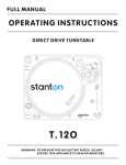
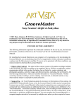
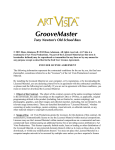
ASSEMBLY
Remove all the parts from the box. Please check to make sure the
following items are included with the main unit in the carton:
(1)
(2)
(3)
(4)
(5)
(6)
(7)
(8)
(9)
Operating instructions
Platter
Slip mat
Counterweight
45-rpm adapter
Headshell
AC cord
Connecting cord
Cartridge
CONNECTIONS
1. Connect the power cord to the auxiliary power outlet on the rear panel
of your amplifier or receiver or to a household AC outlet.
2. Connect the unit output terminals to the PHONO jack of your amplifier
or receiver.
Output terminals
Amplifier (Receiver)
L White)
L Channel
R (Red)
R Channel
GND (Spade)
GND
NOTE:
Be sure to connect the ground terminal firmly to the amplifier or receiver.
If this connection is not made or is loose, a power source "HUM" will
result.
TONE ARM AND CARTRIDGE SETTINGS
The major cause of problems in sound and skipping on the vinyl is the
lack of proper set up of the needle and turntable adjustments. The needle
is designed to operate at a specific angle to the vinyl. The str8-90 has
several adjustments to correctly position the needle to the vinyl.
The first adjustment is the correct installation of the cartridge.
Your cartridge is to be mounted into the headshell as pre the mounting
instructions included with the cartridge. The Stanton 500,680 and 890
series of cartridges require the use of the two screw mounting into the
headshell. For you convenience, some of these products can be
purchased already mounted and pre-adjusted from your local Stanton
dealer. If you are using these 1/2” mounted products with a headshell in a
mobile application or you are doing heavy scratching, May want to use an
extra shell weight. The Master series of products (Trackmaster,
Groovemaster, etc.) are designed with their own mounting that eliminates
the need for a separate headshell and the wiring to the cartridge.
The body of the cartridge should be parallel with the centerline of the
headshell-tone arm, when viewed from the front to the back.
The second adjustment is at the installation of the
cartridge-head-shell assembly into the tone arm tube lock. Holding
the tone arm tube in one hand, insert the cartridge-headshell into the tube
lock with the other hand. Turn the lock ring clockwise (when viewed from
the rear) until the headshell is locked tightly into the tone arm. Remove
the needle protector from the cartridge and place the needle on record.
View the needle from the front and insure that the needle is perpendicular
to the record surface. If some adjustment is needed, simply loosen the
lock ring and rotate the cartridge-headshell until the needle is
perpendicular to the record surface. Then re-tighten the lock ring.
The third adjustment is the needle (or stylus) pressure. Start with the
cartridge-headshell assembly mounted into the tone arm. Remove any
needle protectors provided. With tone arm free, adjust the tone arm
counterweight by rotating the rear section until the tone arm floats in a
balanced condition above the record or mat. Do not allow the needle to
drop onto the mat or the turntable platter during this adjustment. You
might damage the needle tip. Now, carefully hold the tone arm in one
hand while rotating the numbered ring on the front of the counter-weight
with the other hand to the “0” setting. Next, without touching the
numbered ring, Rotate the rear counterweight until the desired needle
pressure reading is next to the line on top of the tone arm tube, See the
instructions. Included with your cartridge for proper settings.
The fourth and last adjustment is that of the tone arm height. This
will set the tone arm pivot and needle relation with the vinyl. Unlock the
tone arm base located in the base of pivot assembly. Rotate the height
adjust ring in the pivot base to read the correct setting for the height
adjust ring in the pivot base to read the correct setting for the height of
the cartridge that you are using. Check the cartridge/arm height table for
the correct setting. Be certain to re-lock the pivot base when adjustment
is completed.
PART NAMES & FUNCTIONS
10) PITCH SLIDER
Use this to change the speed of the platter
when the PITCH button is lit.
11) HEADSHELL LOCKING NUT
Attach the headshell by inserting into the front
end of the tone arm, then turn the locking nut
clockwise with the head shell firmly held
horizontally.
12) TONE ARM
This is a fully manual tone arm. To start
playback, gently place the stylus on the record
using the headshell finger support. Do not drop
the stylus onto the record as it may cause
damage to the diamond tip and to the record.
13) PITCH ON/OFF
The ON setting will allow use of the pitch adjust.
When set of OFF, the pitch control will be
locked at 0%.
1) STROBE DOTS
The dots around the edge of the platter are
used in conjunction with the light located inside
the motor ON/OFF switch. While the platter is
in rotation, the dots help to indicate the speed
of rotation. The speed is lower than the
displayed speed (33,45,78) when the dots are
flowing to the right. It is higher than the
displayed speed (33,45,78) when the dots are
flowing to the left. When the strobe is stopped,
the platter is rotating at the displayed speed.
2) MOTOR ON/OFF SWITCH
As opposed to analog turntables, this is not the
power switch. This switch only turns on or off
the motor. Rotate clockwise to turn on the
motor. The platter will not start spinning until
the start/stop button has been pressed. Rotate
counter-clockwise during playback (off position)
for a slow winding down effect.
3) START/STOP
Press this button to start or stop the platter.
14) TONE ARM BASE
The tone arm base includes the height
adjustment, tone arm rest. See “tone arm and
cartridge settings” for proper adjustments. Note:
No Anti-Skate is needed on straight tonearms.
4) PLATTER REVOLUTION SPEEDS (rpm)
33 rpm – Press 33
45 rpm – Press 45
78 rpm – Press 33 and 45 buttons
simultaneously. To return to 33 or 45-rpm play
mode, just press the desired button.
5) HEASDHELL
When installing a phonograph cartridge, refer
to the installation instructions supplied by the
cartridge manufacture.
6) TAGRET LIGHT
Press the button to light up the stylus. To
retract the light, press down on the light itself.
7) REVERSE
This button is used to reverse the direction of
the platter rotation.
8) PITCH SELECT
Press the button to switch between
+/-8%,+/-16%, or +/-25% pitch range.
9) PITCH BEND
The pitch will increase/decrease by up to 6%
while the pitch bend minus button is pressed.
15) COUNTERWEIGHT
Use this to balance the tone arm and to adjust
the stylus pressure.
16) HEADSHELL HOLDER
This is used to place extra headshell during a
performance for quick access.
17) OUTPUT
This is the standard analog output (RCA jacks)
which can be connected to a phono input on
any DJ mixer.
18) GND
Ground wire connection post
19) POWER SETICH
This switch turns the power on or off, including
the motor and audio signal.
20) POWER CORD CONNECTOR
Used to connect the included power cord.
SCRATCH PROTECTION
The STR8-90 includes a
pair of rubber protectors.
These were designed to
protect the turntable’s
rounded aluminum edges
from the mixer while
scratching. When the
turntables are placed
sideways, the round edges
of the turntable may come
in contact with the mixer’s
rack ears causing damage
to the turntable body. Placing the rubber protectors on the mixer rack
ears (see picture) will prevent the turntable from getting scratched.
WARRANTY
This unit has been designed and manufactured using quality components.
Therefore, it is warranted to be free from defects in materials (limited as
specified below), and workmanship for a period of twelve (12) months
from the original purchase date. During this period, all service and parts
necessary to repair a defect will be free of charge. This limited warranty
applies to mechanical parts which are subject to wear and tear as
specified: Faders, specified durability: 50,000 cycles; 10,000 cycles;
Switches, specified durability: 10,000 cycles. Consequently, the parts
listed above are warranted to be free from defects in materials and
workmanship for a period of thirty days (30) days from the original
purchase date.
Note: For the warranty to be valid, please complete the online
warranty registration form found at www.stantonmagnetics.com.
Stanton Magnetics, INC. 3000 SW 42nd Street x Hollywood, FL 33312
Tel: (954) 689-8833 Fax: (954) 689-8460
Email: [email protected]
SPECIFICATIONS
TURNTABLE SECTION
Starting Torque:
Motor:
Platter:
Pitch:
Brake:
TONE ARM SECTION
Tone arm type
Effective Arm Length
Tracking Force Adjust Range
Applicable Cartridge Weight
Frequency Response
Channel Separation
Channel Balance
Wow & Flutter:
S/N ratio:
Needle Pressure range
GENERAL SPECIFICATIONS
Dimensions:
Weight:
Power supply:
Power consumption:
More than 2.2kgf.com
16pole, 3phase, brushless DC motor
330mm dia. Aluminum diecast
+/-8%,+/-16%,+/-25%
Electronic brake
Static balanced straight
tonearm with Cardan suspension
191mm
0-4g
6-10g
20 - 20 kHz
More than 15 dB
Within 2.5dB at 1 KHz
Less than 0.20% WRMS
(JIS WTD) with 33 1/3rpm
More than 50dB (DIN-B)
1.5-2g
450(W) x 370 (D) x 140 (H)mm
17-3/4" x 14-5/8" x 5.5" (WxDxH)
9.9Kg (21.8 lbs.)
AC 100V, 50/60Hz
12W