1
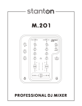
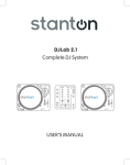
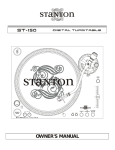
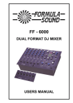
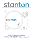
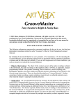
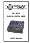
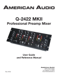
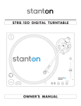
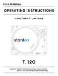
DJLab.3
OWNER'S MANUAL
S T A N T O N MA G N E T I C S , I N C
[email protected] + 1 954- 689-8833
w w w . s t a n t o n d j . c o m
IMPORTANT TO SAFETY
1.
2.
3.
4.
5.
6.
7.
8.
9.
10.
11.
Read these Instructions
Keep these Instructions
Heed all Warnings
Follow all Instructions
Do not use this apparatus near water
Clean only with dry cloth
Do not block any ventilation openings. Install in
accordance with the manufacturer’s instructions.
Do not install near any heat sources such as radiators,
hear registers, stoves, or other apparatus (including
amplifiers) that produce heat.
Do not defeat the safety purpose of the polarized or
grounding-type plug. A polarized plug has two blades with
one wider than the other. A grounding type plug has two
blades and a third grounding prong. The wide blade or the
third prong are provided for your safety. If the provided plug
does not fit into your outlet, consult an electrician for
replacement of the obsolete outlet.
Protect the power cord from being walked on or pinched
particularly at plugs, convenience receptacles, and the
point where they exit from the apparatus.
Only use attachments/accessories specified by the
manufacturer.
12.
Use only with the cart, stand, tripod,
bracket, or table specified by the
manufacturer, or sold with the apparatus.
When a cart is used, use caution when
moving the cart/apparatus combination to
avoid injury from tip-over.
13.Unplug this apparatus during lightning storms or when
unused for long periods of time.
14. Refer all servicing to qualified Stanton service center.
Servicing is required when the apparatus has been
damaged in any way, such as power-supply cord or plug
is damaged, liquid has been spilled or objects have
fallen into the apparatus, the apparatus has been
exposed to rain or moisture, does not operate normally,
or has been dropped.
15. This appliance shall not be exposed to dripping or
splashing water and that no object filled with liquids
such as vases shall be placed on apparatus.
IMPORTANT SAFETY INSTRUCTIONS
CAUTION
CAUTION: To reduce the risk of electric shock, do not remove
the cover (or back). No user-serviceable parts inside. Refer
servicing to qualified service personnel.
The lightning flash with arrowhead symbol within an equilateral triangle is intended to alert the use to
the presence of un-insulated “dangerous voltage” within the product’s enclosure that may be of
sufficient magnitude to constitute a risk of electric shock to persons.
The exclamation point within the equilateral triangle is intended to alert the user to the presence of
important operating and maintenance (servicing) instructions in the literature accompanying the
appliance.
CAUTION
To prevent electric shock, do not use this polarized plug with an extension cord, receptacle or other outlet unless
the blades can be fully inserted to prevent blade exposure.
LINE VOLTAGE SELECTION
115V
1)
The desired voltage of your turntable may be set with the VOLTAGE SELECTOR switch on the
rear panel of the main unit, using a screwdriver.
2)
Do not twist the VOLTAGE SELECTOR switch with excessive force as this may cause damage.
230V 3) If the VOLTAGE SELECTOR switch does not move smoothly contact a qualified serviceman.
M.202 FEATURES
3 band EQ w/ input GAIN control per channel.
Power on/off muting.
Long-lasting crossfader.
Crossfader Start Function
M.202 CONTENTS
4
2
6
11
10
14
9
3
1
15
12
13
5
7
8
M.202 CONTENTS
When used with a compatible CD player, you can use
the crossfader to start and stop the CD player with the
slide of the fader. The fader start switch activates the
fader start feature. When in the ON position, the fader
start allows the fader to return automatically to preset
digital CUE POINTS on your compatible STANTON DJ
CD Player.
14) Mic EQ – The mic channel include a two-band EQ with a
range of +10dB to –10dB.
22 21
20
19 18 17 16
1) Input fader - Controls individual source levels/volume
(channels) in the mix.
2) Input toggle switch - Selects which source will be active
based on what you have connected to the rear panel
input section (phono/line).
3) Channel EQ - Adjusts the high, mid and low
frequency levels of the input channels for good
sound.
4) Channel Gain – Adjusts the pre-fader volume for
cleaner sound.
5) Replaceable Crossfader - Achieves clean fades
between the two input channels. "Hard left" selects
Channel 1. "Hard right" selects Channel 2. With the
crossfader centered, both channels are live. Use
the crossfader for fast and seamless fades from
one channel to the other.
6) Mic Input Gain – Adjusts microphone input level.
7) Mic Input – Insert your Microphone with ¼” plug here.
8) Headphone Output – Insert in the ¼” plug for your
headphones here.
9) Channel Cue / Cue Pan - Used to preview channel
audio to your headphones. Listen here before bringing
up channel faders or moving the crossfader.
15) Level Indicators – The dual LED indicators are used to
indicate the master output level of channels Right and
Left.
16) Grounding post - for turntable connection. Always use
this connection when using standard turntables with
ground cable. (Some turntables like the T.80 / T.120 do
not require grounding wire)
17) Phono Inputs – Plug your turntables in here. When these
connectors are used, your signal is fed directly to the
high-quality RIAA phono pre-amplifiers. Use this position
only for turntables. Line level sources will overload the
sensitive phono pre-amps and will cause distortion.
18) Line Inputs - Unbalanced RCA jacks for connecting
stereo audio from line level sources such as CD players,
HiFi VCRs, cassette decks, DAT machines, laser discs,
tuners, even synthesizers or other mixing consoles.
NOTE: Plug mono audio sources into both Left and
Right inputs using a "Y" cable connector.
19) Master Output - Unbalanced RCA connectors controlled
by the Master level.
20) Fader Start – This function works in conjunction with a
compatible fader start CD player. When used with a
compatible CD player, you can use the crossfader to
start and stop the CD player with the slide of the fader.
The fader start switch activates the fader start feature.
When in the ON position, the fader start allows the fader
to return automatically to preset digital CUE POINTS on
your compatible STANTON DJ CD Player.
21) Power Connector - Plug in the included power supply
here.
10) Headphone Level – Adjusts cue volume.
11) Master Level - Controls the overall output level.
12) Crossfader Curve – The CUT setting allows the use of the
crossfader for quick cut in and out when scratching and
mixing. The FADE setting is used for longer segues,
typically when mixing between two beat-matched
sources.
13) Fader start – This function works in conjunction with a
compatible fader start CD player.
22) Power Switch – turns unit off and on. Note*** Remember
to turn ALL volume levels down when turning the unit
on/off.
QUICK SETUP DIAGRAM
Study this setup diagram. Make sure all faders are at "zero" and all devices are off. First, connect all input sources. Next,
connect your microphone and monitor headphones. Finally, connect the stereo outputs to the power amplifier(s) and/or audio
receivers such as tape decks. Plug your mixer into AC power. Now you are ready to switch everything on. IMPORTANT:
Always switch on your audio input sources such as turntables or CD players first, then your mixer, and finally any amplifiers.
When turning off, always reverse this operation by turning off amplifiers, then your mixer, and then input devices.
TURNTABLE
POWER
SUPPLY
SOUND SYSTEM
TURNTABLE
CD PLAYER CONTROLLER
CD PLAYER
SPECIFICATIONS
M.202
INPUT / OUTPUT IMPEDANCE & SENSITIVITY:
LINE
-14dB/10K OHM
±2dB
PHONO -50dB /47K OHM
±2dB
MIC
-60dB /2.2K OHM
±2dB
MASTER 1K OHM
PHONES 0dB/33 OHM ±2dB (LOAD=32 OHM)
MAX. OUTPUT (THD=1%)
MASTER MORE THAN +14dBV
PHONES MORE THAN +21dBV
CHANNEL BALANCE
WITHIN 3dB
FREQUENCY RESPONSE:
LINE
20-20KHz ±2dB
PHONO 20-20KHz +2, -3dB (RIAA)
MIC
20-20KHz +2/-3dB
OUTPUT NOISE (IEC-A WEIGHTED)
LINE
LESS THAN -90dBV
PHONO LESS THAN -80dBV
MIC
LESS THAN -50dBV
THD + N:
LINE
PHONO
MIC
PHONES
(MASTER 0dBV OUTPUT, MAXIMUM GAIN, w/ 20kHz LPF)
LESS THAN 0.05% 20 - 20KHz
LESS THAN 0.1% 20 - 20KHz (IEC-A WTD)
LESS THAN 0.2% 20 - 20KHz (IEC-A WTD)
LESS THAN 0.1% 20 - 20KHz (FROM LINE INPUT)
CROSSTALK
MIC EQ
HI
LOW
LESS THAN -80dB AT 1KHz BETWEEN CHANNELS.
(TERMINATED UNUSED INPUTS)
±10 +/- 2dB AT 10KHz
±10 +/- 2dB AT 100Hz
CHANNEL EQ
HI
9 +/- 2dB AT 13KHz
-15 +/- 3dB AT 13KHz
MID
9 +/- 2dB AT 1KHz
LESS THAN -23dB AT 1KHz
LOW
9 +/- 2dB AT 70Hz
-26 +/- 3dB AT 70Hz
POWER SOURCE
AC 9V,1000mA
DIMENSIONS
230 (W) X 267 (D) X 111 (H) mm
WEIGHT
1.65Kgs
CONNECTIONS
1) Connect the power cord to an AC outlet.
2) Connect the RCA cable to the PHONO input of your mixer. You can also use a line input by setting the
phono/line switch at the rear of the turntable to Line.
Note: This turntable has separate analog and digital circuits. If you are looking for a purely analog signal, use the
Phono output. For access to the Key Lock feature use the Line output or S/P DIF output.
T.80 TURNTABLE CONTENTS
17
16
18
1
15
14
2
13
3
12
4
11
10
5
9
6
7
19 20 21
22
8
T.80 TURNTABLE CONTENTS
1)
2)
3)
4)
5)
6)
7)
8)
9)
10)
11)
12)
13)
14)
15)
16)
17)
18)
19)
20)
21)
22)
Start/Stop
Strobe Dots
Slipmat
Center Spindle
Motor ON/OFF Switch
Platter Revolution Speeds (RPM)
Target Light Base
Key Lock
Pitch Lock
Pitch Slider
Headshell Locking Nut
Tonearm
Pitch Select
Tone Arm Base
Counterweight
45-rpm Adaptor Holder
Extra Stylus Holder
Reverse
Phono/Line Output
Phono/Line Switch
Digital Output
Power Cord Connector/Power Switch
TONE ARM AND CARTRIDGE SETTINGS
The major cause of problems in sound and skipping on the vinyl is the lack of proper set up of the needle and turntable
adjustments. The needle is designed to operate at a specific angle to the vinyl. The T.80 has several adjustments to correctly
position the needle to the vinyl.
The first adjustment is the correct installation of the cartridge.
Your cartridge is to be mounted into the headshell as pre the mounting instructions included with the cartridge. The Stanton
500,680 and 890 series of cartridges require the use of the two screws mounting into the headshell. For your convenience,
some of these products can be purchased already mounted and pre-adjusted from your local Stanton dealer. If you are using
these 1/2” mounted products with a headshell in a mobile application or you are doing heavy scratching, May want to use an
extra shell weight. The Master series of products (Trackmaster, Groovemaster, etc.) are designed with their own mounting that
eliminates the need for a separate headshell and the wiring to the cartridge.
The body of the cartridge should be parallel with the centerline of the headshell-tone arm, when viewed from the front to the
back.
The second adjustment is at the installation of the cartridge-head-shell assembly into the tone arm tube lock. Holding
the tone arm tube in one hand, insert the cartridge-headshell into the tube lock with the other hand. Turn the lock ring
clockwise (when viewed from the rear) until the headshell is locked tightly into the tone arm. Remove the needle protector from
the cartridge and place the needle on record. View the needle from the front and insure that the needle is perpendicular to the
record surface. If some adjustment is needed, simply loosen the lock ring and rotate the cartridge-headshell until the needle is
perpendicular to the record surface. Then re-tighten the lock ring.
The third adjustment is the needle (or stylus) pressure. Start with the cartridge-headshell assembly mounted into the tone
arm. Remove any needle protectors provided. With tone arm free, adjust the tone arm counterweight by rotating the rear
section until the tone arm floats in a balanced condition above the record or mat. Do not allow the needle to drop onto the mat
or the turntable platter during this adjustment. You might damage the needle tip. Now, carefully hold the tone arm in one hand
while rotating the numbered ring on the front of the counter-weight with the other hand to the “0” setting. Next, without touching
the numbered ring, Rotate the rear counterweight until the desired needle pressure reading is next to the line on top of the tone
arm tube, see the instructions. Included with your cartridge for proper settings.
ASSEMBLY
Remove all the parts from the box. Please check to make
sure the following items are included with the main unit in the
carton:
(1)
(2)
(3)
(4)
Platter
Slip mat
Counterweight
45-rpm adapter
(5)
(6)
(7)
(8)
(9)
(10)
500B Cartridge and Headshell
AC cord
RCA cable
Target light
Operating instructions
Cloth dust cover
SPECIFICATIONS
T.80
POWER SOURCE
AC 100V, 50/60Hz (For Japan)
AC 110V, 60Hz (For Taiwan)
AC 120V, 60Hz (For U.S.A.,Canada,Mexico)
AC 220V, 50Hz (For United Arab Emirates,Chile,Argentina)
AC 220V, 60Hz (For Philippines)
AC 230V, 50Hz (For Europe,New Zealand,South Africa,Singapore,Israel)
AC 240V, 50Hz (For Australia,U.K.)
POWER CONSUMPTION 10 Watts
DIMENSIONS
452 (W) x 370 (D) x 86 (H) mm
WEIGHT
8.6 Kgs
Stanton Magnetics, Inc. – Warranty Provision – Returns for Repairs or Replacement
WARRANTY
Through Stanton’s authorized dealers around the World, Stanton, or one of Stanton’s authorized distributors outside the
U.S., will, without charge, repair or replace, at the sole discretion of the entity responsible for making the repair or
providing the replacement, any Stanton merchandise proved defective in material or workmanship for a period of one (1)
year following the date of original purchase. Exceptions to this warranty are as noted below:
The warranty for mechanical parts which are subject to wear and tear are limited to the earlier to occur of thirty (30) days
following the date of original purchase or the following number of cycles: Faders - 15,000; Rotary potentiometers - 10,000;
and Switches - 10,000.
Stanton will warrant all replacement parts and repairs for ninety (90) days from the date of original shipment. Repairs
made necessary by reason of misuse, alteration, normal wear, or accident are not covered under this warranty.
RETURNS
Authorized Stanton dealers are only authorized to sell and distribute merchandise within a specific country. All goods
requiring warranty repair or replacement must be returned (freight prepaid if not hand-delivered) to the authorized Stanton
dealer from whom the merchandise was purchased and in the same country where the merchandise was purchased. For
purposes of purchases made via the Internet, the merchandise must be returned to the authorized Stanton dealer in the
country where the authorized Stanton dealer which sold the merchandise to purchaser is located and not the authorized
Stanton dealer in the country where the purchaser is located or the country in which the merchandise was received. Any
returns to a non-authorized dealer or to an authorized Stanton dealer not in the same country as the merchandise was
intended to be sold or as set forth above will void this warranty.
To initiate a warranty repair, you must contact the authorized Stanton dealer from whom you purchased the merchandise,
and follow such authorized Stanton dealer’s return policy.
Stanton assumes no risk and shall be subject to no liability for damages or loss resulting from the specific use or
application made of the merchandise. Stanton's liability for any claim, whether based on breach of contract, negligence,
infringement of any rights of any party, or product liability, and relating to the merchandise shall not exceed the price
received by Stanton from your purchase of such merchandise. In no event will Stanton be liable for any special, incidental
or consequential damages (including loss of use, loss of profit and claims of third parties) however caused, whether by the
negligence of Stanton or otherwise. To the extent permitted by law and except as otherwise provided above, Stanton
disclaims any express or implied warranties of merchantability or fitness for a particular purpose.
The above warranty provides you with specific legal rights. You may also have additional rights, which are subject to
variation from state to state and country to country.
If there is a dispute regarding the warranty of merchandise that does not fall under the warranty conditions stated above,
please include a written explanation with the merchandise when returned pursuant to the terms and conditions set forth
herein.
Please register your product online at www.stantondj.com or mail your completed warranty card to:
Stanton Magnetics, Inc, 3000 SW 42 St. Hollywood, Florida 33312.
cut along dotted line
State
Where did you buy this product?
Date of Purchase
Serial Number
Model Number
PRODUCT INFO
Telephone
Country
City
Address
Name
PERSONAL INFO
Zip
If you have internet access, please register your product at
www.stantondj.com. Otherwise, return this card completely filled
out in order to validate your warranty.
STANTON WARRANTY REGISTRATION CARD
PLACE
STAMP
HERE
Stanton Magnetics, Inc.
3000 SW 42nd Street
Hollywood, FL 33312
U.S.A.