1
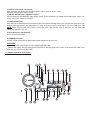
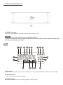
Professional Dual CD Player
C.503
User Manual
Congratulations and thank you for purchasing the latest addition to the growing Stanton family of professional DJ gear.
Sporting a new attitude and a fresh, modern look, the Stanton C.503 is a dual rackmount CD player with designed to
give club and mobile DJs a powerful, yet simple tool to mix, create, and perform their best.
Designed for DJs who want solid, reliable performance and the latest technology, the workhorse C.503 boasts powerful
features like scratching, seamless looping, programmable hot cue points, plus digital Key Lock and Key Shift functions
for creating more exciting mixes. Thoughtfully designed and engineered to give you the most intuitive and instinctual
experience possible, the C.503 delivers all these features in a logical layout with quality components at a price working
DJs can afford. We’re proud to bring you the new look, feel, and sound of Stanton.
SAFETY PRECAUTIONS
WARNING: TO PREVENT FIRE OR SHOCK HAZARD, DO NOT EXPOSE THIS APPLIANCE TO RAIN OR MOISTURE.
CAUTION:
• Handle the power supply cord carefully. Do not damage or deform the power supply cord. If it is damaged, cut, or
deformed, it may cause electric shock or malfunction when used. When removing from wall outlet, be sure to remove
by holding the plug attachment and not by pulling the cord.
• In order to prevent electric shock, do not open or disassemble. If a problem occurs, contact your dealer or an
authorized service center.
• Do not place metal objects or spill liquid inside the CD player. Electric shock or malfunction may result.
• To reduce the risk of electric shock, do not remove any cover. No user-serviceable parts inside. Refer servicing to
qualified service personnel only.
• The lightning flash with arrowhead symbol within the equilateral triangle is intended to alert the user to the presence of
un-insulated “dangerous voltage” within the product’s enclosure that may be of sufficient magnitude to constitute a risk
of electric shock.
• The exclamation point within the equilateral triangle is intended to alert the user to the presence of important operation
and maintenance (servicing) instructions in the literature accompanying this appliance.
• Product complies with DHHs rule 21 CFR subchapter J in effect at date of manufacture.
• To prevent electric shock, do not use this (polarized plug) with an extension cord, receptacle or other outlet unless the
blades can be fully inserted to prevent blade exposure.
NOTE:
This CD player uses a semiconductor laser. For optimal operation, it is recommended that this unit be used in a room with
temperatures between 41°F / 5°C and 95°F / 35°C.
This unit may cause interference to radio and television reception.
CAUTION:
USE OF CONTROLS OR ADJUSTMENTS OR REFORMANCE OF PROCEDURES OTHER THAN THOSE SPECIFIED
HEREIN MAY RESULT IN HAZARDOUS RADIATION EXPOSURE.
THE COMPACT DISC PLAYER SHOULD NOT BE ADJUSTED OR REPAIRED BY ANYONE EXCEPT PROPERLY QUALIFIED SERVICE PERSONNEL.
DOUBLE INSULATED – WHEN SERVICING, USE ONLY IDENTICAL REPLACEMENT PARTS
Please record and retain the model and serial numbers of your CD player as shown on the rear of the unit.
Model #:____________________
Serial #:_____________________
1 Read these instructions.
2 Keep these instructions.
3 Heed all warnings.
4 Follow all instructions.
5 Do not use this apparatus near water.
6 Clean only with dry cloth.
7 Do not block any ventilation openings. Install in accordance with the manufacturerÅfs instructions.
8 Do not install near any heat sources such as radiators, heat registers, stoves, or other apparatus (including amplifiers) that produce
heat.
9 Do not defeat the safety purpose of the polarized or grounding-type plug. A polarized plug has two blades with one wider than the other.
A grounding type plug has two blades and a third grounding prong. The wide blade or the third prong are provided for your safety. If the
provided plug does not fit into your outlet, consult an electrician for replacement of the obsolete outlet.
10 Protect the power cord from being walked on or pinched particularly at plugs, convenience receptacles, and the point where they exit
from the apparatus.
11 Only use attachments/accessories specified by the manufacturer.
12 Use only with the cart, stand, tripod, bracket, or table specified by the manufacturer, or sold with the apparatus. When a cart is used,
use caution when moving the cart/apparatus combination to avoid injury from tip-over.
13 Unplug this apparatus during lightning storms or when unused for long periods of time.
14 Refer all servicing to qualified service personnel. Servicing is required when the apparatus has been damaged in any way, such as
power-supply cord or plug is damaged, liquid has been spilled or objects have fallen into the apparatus, the apparatus has been exposed
to rain or moisture, does not operate normally, or has been dropped.
- Do not expose this apparatus to drips or splashes.
- Do not place any objects filled with liquids, such as vases, on the apparatus.
- Do not install this apparatus in a confined space such as a book case or similar unit.
- The apparatus draws nominal non-operating power from the AC outlet with its POWER switch in the off position.
TABLE OF CONTENTS
1. Functions and Controls (Layout)
1-1. Main Unit (Front Panel)
1-2. Main Unit (Rear Panel)
1-3. Remote Controller (Front Panel)
1-4. Remote Controller (Bottom Panel)
1-5. LCD
2. Standard Operation
2-1. CUE
2-2. MEMORY/CUE
2-3. Flash Start
2-4. Looping
2-5. Adjusting the tempo
2-6. Pitch Bending
2-7. KEY LOCK
2-8. PITCH LOCK
2-9. BPM/TAP
3. Advanced Operation
3-1. KEY SHIFT
3-2. BRAKE
3-3. VINYL
3-4. Track Memory
3-5. Fader Start
3-6. Relay Play
3-7. Auto Cue
3-8. Program Play
3-9. Preset Menu
3-10. Back Up Memory
4. Specifications
5. Error Messages (Troubleshooting)
FUNCTIONS & CONTROLS
11. Main Unit (Front Panel)
1. Disc Trays
Insert CDs into these trays, label side upwards.
NOTE:
The C.503 reads Audio from CDs & CD-Rs. + Audio Only CD-RWs
2. Tray LEDs
When power is turned on, these two LEDs will light.
3. OPEN/CLOSE Buttons
Open and close the appropriate disc tray. To avoid mistakes direct mode is off by default, therefore the CDs cannot be
ejected when in Play mode.
NOTE:
Direct Mode allows the CD to eject regardless of play / status (see Preset Menu)
4. POWER switch
Turns the power on and off. The tray LEDs light blue when power is supplied.
When the Timer Start function is on, playback begins when power is supplied.
1-2. Main Unit (Rear Panel)
5. OUTPUT jacks (RCA, unbalanced)
RCA connectors providing line level output signals, one set each for discs 1 and 2.
Maximum output level is +6dBV (2Vrms)
6. DIGITAL OUTPUT jacks (COAXIAL, S/PDIF)
Coaxial connectors provide S/DIF digital output signals. These connectors can output the 44.1KHz digital signals constantly even if pitch control is activated.
7. FADER START jacks
The C.503 can be controlled using the external fader start command through these jacks. Connect the mixer which supports the fader start function with appropriate 1/8” Fader Start cable as well as audio signal. (TIP: Start, GND: back cue)
NOTE: When using the fader start function, connect the audio signal with the mixer as well. Also, two 1/8” fader start
cables are supplied in this unit.
8. AUX connectors (not included)
This is for future expansion.
9. REMOTE connector
Use this included connector to connect the remote controller to the main unit.
WARNNING
* DO NOT use any cable except the cable supplied with the C.503.
* Connect the cable in the way shown on the illustration on the rear panel of the C.503. If you connect the cable in any
other way, you may damage the C.503.
1-3. Remote Controller (Front Panel)
10. Jog wheel
The following functions can be controlled by using the Jog wheel:
* Pitch Bend
* VINYL / Scratch
* Brake time
* KEY SHIFT control
* Preset menus [SHIFT + Jog Wheel]
* Effect parameters
* Program edit
* Track memory number select
* Search (in Paused mode)
11. OPEN/CLOSE [RESET] Button
Opens and closes the appropriate tray. When DIRECT mode is off (in preset menu) and disc is being played back, these
buttons cannot be used.
Pressing and holding the SHIFT button then pressing this button clears all track memories and initializes the preset
menu.
12. SHIFT Button
The SHIFT button is a modifier button. Any button outlined with a silver border or box has a shift function / feature. This
feature is written above or below the button itself. Holding SHIFT while pressing another button performs the following
functions:
SHIFT + OPEN/CLOSE
Clears the all track memories and initializes the preset menu.
= [RESET]:
SHIFT + CTN/SGL
= [PROGRAM]:
Enters the program edit mode and program play mode.
SHIFT + TIME/ENTER
= [RECALL DISPLAY]:
Selects the parameter display mode and enters the track memory recall mode.
SHIFT + PITCH RANGE
= [BANK]:
Selects the memory bank for the track memory (A-E).
SHIFT + MEMORY/CUE
= [MEMO INS]:Enters the track memory store mode.
SHIFT + LOOP
= [REPEAT DEL]:
Selects the repeat play mode and deletes tracks while in memory mode.
SHIFT + PLAY/PAUSE
= [RELAY PLAY]:
Toggles the RELAY PLAY function on and off.
SHIFT + CUE
= [AUTO CUE]:
Toggles the AUTO CUE function on and off.
SHIFT + JOG: Enters preset menu mode.
For more information on SHIFT functions read below and see advanced operation.
13. LCD
Displays visual feedback for C.503 functions.
14. SELECT Buttons
Use these to perform track searches (next / previous) track. Search from track to track, either forward (up arrow) or backward (down arrow) with these buttons.
15. SEARCH Buttons
Search within the track selected, either forward >> or backward << with these buttons. When unit is pausing, pressing
this button shortly moves the start / cue point in 1 frame steps. This also enters is stutter mode.
16. CTN/SGL [PROGRAM] Button
Selects the play mode, either continuous or single mode.
Pressing and holding the SHIFT button then pressing this button enters the program edit mode and program play mode.
When unit is in single play mode, “SGL” indicator in the LCD will light.
When unit is in program play mode, “PGM” indicator in the LCD will light.
17. TIME/ENTER [RECALL DISPLAY] Button
Changes the time mode between elapsed time and remain time. When time mode is set to remain, “REMAIN” indicator
in the LCD will light. When in preset mode, pressing this button confirms the current setting.
Pressing and holding the SHIFT button then pressing this button selects the mode of parameter display in the LCD from
TEMPO, KEY, TAP, BPM, and track memory recall function.
18. PITCH RANGE [BANK] Button
Selects the pitch range from +/-4, 8, 16, 32, and 100%. The selected pitch range is displayed momentarily displayed in
the parameter section of the LCD screen.
Pressing and holding the SHIFT button then pressing this button selects the memory bank for track memory. The selected bank (A-E) will light in the LCD.
19. KEY SHIFT Button
Turns the KEY SHIFT function on and off. When KEY SHIFT function is turned on, this button will light blue. Pressing
and holding this button then using the Jog wheel selects the Key Shift value. When Key Shift value is set to other than
0% internally, KEY indicator in the LCD will light.
NOTE:
When KEY LOCK function is activated, KEY SHIFT function cannot be turned on.
NOTE:
Turning off KEY SHIFT does not return KEY to original value. This must be done manually by re-adjusting KEY SHIFT
to its original value (via Jog Wheel / Pitch Bend)
20. KEY LOCK Button
Turns the KEY LOCK function on and off. When KEY LOCK function is turned on, “KEY LOCK” indicator in the LCD
screen will light.
21. BPM/TAP Button
Sets the tempo in BPM by tapping this button. When you press this button, the parameter counter mode momentarily
changes to BPM display mode. Pressing this button more than 1.5 seconds erases the tapped BPM. Pressing and holding this button then using Jog wheel adjusts the BPM in 0.1% increments. When the unit recognizes the BPM, this button will flash in sync with the BPM.
22. VINYL Button
Turns the vinyl mode (scratch play mode) on and off. When vinyl mode is turned on, this button will light blue and
scratching can be performed by using Jog wheel.
23. BRAKE Button
Turns the brake function on and off.
Pressing and holding this Button then using the Jog wheel adjusts the brake time.
24. PLAY/PAUSE [RELAY PLAY] Button
Changes the playback mode between play and pause.
The light stays on solid green in playback mode and flashes in pause mode
Pressing and holding the SHIFT Button then pressing this Button toggles the RELAY PLAY on and off.
25. CUE Button [AUTO CUE]
Locates to the cue point, then pauses.
Pressing and holding this Button when pausing the CUE point, play start from the CUE point and releasing this Button
returns the CUE point again (Stutter play). At this time (playing with holding the CUE Button), pressing the PLAY Button
enters into the normal playback mode.
Pressing and holding the SHIFT Button then pressing this Button toggles the AUTO CUE function on and off.
26. MEMORY/CUE [MEMO/INS] Button
Activates the three buttons below (1/IN, 2/OUT, and 3/RELOOP) ready for CUE mode. When these three buttons are set
to CUE mode, this button will light green, press again to SET cue for bank 1, 2, or 3. NOTE: > Pressing and holding the
SHIFT then pressing MEMORY/CUE enters the track memory store mode (MEMO/INS).
NOTE:
Memory store mode allows the user to store track memory in several banks (A – E). For more information on memory
store mode see section 3-4 Track Memory.
When unit is in program edit mode, pressing this button inserts a program track.
For more information on the insert function see section 3-8 Program Play.
27. LOOP [REPEAT/DEL] Button
Enters the three buttons (1/IN, 2/OUT, and 3/RELOOP) ready for LOOP mode. When these three buttons are set to
LOOP mode, this button will light. When loop play is engaged, pressing this button exits the loop play. Pressing and holding SHIFT then pressing this LOOP changes the repeat mode on or off. When repeat mode is set to single repeat, “SGL”
and “RPT” indicators in the LCD will light. When repeat mode is set to all repeat, only “RPT” indicator will light. When
unit is in program edit mode, pressing this button deletes a program (track).
28. 1/IN Button
29. 2/OUT Button
30. 3/RELOOP Button
These three buttons have the following three functions:
CUE mode:
SAMPLER mode:
LOOP mode:
Store the in CUE points or play them seamlessly.
Create the IN & OUT points of a Sample, and playing it.
Create the IN & OUT points of a Loop, and re-loop.
31. PITCH LOCK
Sets the pitch range to 0%. At this time, TEMPO display shows “- - -“ and LED that is placed in center of the pitch fader
will light, even if Pitch Fader is not located to the center. This indicates the Pitch has been “Locked” at zero.
NOTE:
When PITCH LOCK button is pressed, KEY SHIFT and KEY LOCK functions are turned off automatically.
32. PITCH BEND
Use these buttons to perform pitch bending.
33. Pitch Fader
Changes the playback pitch, according to the range set by PITCH RANGE button. When playback pitch is set to 0% or
PITCH LOCK is turned on, the LED will light.
1-4. Remote Controller (Bottom Panel)
34. REMOTE connector
Connect this to the REMOTE connector on the rear panel of the main unit.
WARRNING
* DO NOT use any cable except the cable supplied with the C.503.
* Connect the cable to the C.503 as shown on the illustration on the rear panel. If you connect the cable in any
other way, you may damage the C.503.
1-5. LCD
35. M indicator
If there is track memory data for the current selected track in the current selected memory bank, this indicator lights.
36. TRACK indicator
Shows the current track selected / playing.
37. REMAIN indicator
When the time mode is set to time remaining mode, this indicator lights.
38. SGL indicator
When the play mode is set to single play, this indicator lights.
39. RPT indicator
When the play mode is set to either single repeat or all repeat play mode, this indicator lights.
40. PGM indicator
When the play mode is set to programmed play, this indicator lights.
41. Time display
This section is used to show track number, time values or messages.
42. Memory bank indicators
Lights the current selected memory bank indicator.
43. A.CUE indicator
Lights when AUTO CUE function is turned on.
44. RELAY indicator
Lights when relay play is set to on.
45. LOOP indicator
Lights when sampler loop play is engaged.
46. Time Address Bar
Shows the current play position relative to the currently selected track.
47. PAR indicator
Lights when parameter display shows the effect parameter.
48. TEMPO indicator
Lights when parameter display shows the TEMPO / PITCH value.
49. KEY indicator
Lights when parameter display shows the key value.
Lights when key value is set to other than 0 (zero).
50. Parameter display
Displays the various parameters (of 47-51)
51. TAP / BPM indicator
Lights when parameter display shows the tap / BPM value.
52. KEY LOCK indicator
Lights when KEY LOCK function is activated.
2-1. CUE
The C.503 will always memorize the last played start point as the main cue point. After play has begun, pressing the
CUE button re-locates the audio and plays it from that point. Although very quick, the CUE button is not seamless.
NOTE:
To create a new cue point, simply find the desired location and press PLAY. The last location when play was pressed is
now the current the cue point). This can be done with or without stutter mode (using jog wheel or search buttons)
Stutter play with the CUE Button
Once a CUE point has been created, the unit will play when this button is pressed, and enter pause mode when CUE
button is released. If the PLAY button is pressed during CUE playback, the unit will go into normal play mode.
2-2. MEMORY/CUE
The C.503 can have three flash (seamless) cue points stored with the CUE 1-3 buttons. These other cue points can be
done “on-the-fly” (without pressing play or pausing the audio) or in stutter mode (using the Jog Wheel or Search buttons)
To memorize the CUE 1-3 points
1. Press MEMORY/CUE button to enter the unit into MEMORY/CUE mode (if not already lit this button will light up green.
2. Find the desired point in audio where you want to create a CUE point.
3. Press the MEMORY/CUE button until the parameter display in LCD shows “SEt”.
4. Press the desired CUE button (1, 2, or 3) within 5 seconds to store the desired CUE point in that bank.
NOTE:
When the bank buttons (1, 2, or 3) has a point stored the button lights up green. The stored cue point cannot be erased
but can be overwritten.
When the unit is paused, pressing the MEMORY/CUE button then pressing the bank button (1, 2, or 3) starts the unit
automatically, and stores it as a cue point.
For three seconds after storing one of the cue points, you cannot store another cue point.
2-3. Flash Start (Seamless Cue)
The flash start (seamless cue) function can be performed with the CUE (1, 2, or 3) buttons. After storing the point, pressing any of these buttons performs a flash start / seamless cue.
2-4. IN/OUT Looping
To store the LOOP points
NOTE:
The three buttons (1/IN, 2/OUT, and 3/RELOOP) are shared for MEMORY/CUE and LOOP functions. Therefore, only
one of these three functions (MEMORY/CUE or LOOP function) can be used at a time. (i.e. loop cannot be used simultaneous with memory/cue)
1. Press LOOP button to enter the unit into LOOP mode. LOOP button will light green.
2. Press the IN button while in play or in pause mode. The IN button will light and the OUT button will start flashing.
3. Press the OUT button while in play or in pause mode. IN, OUT, and RELOOP buttons will all light. If the loop end point
is set when the unit is playing, the C.503 starts loop playback seamlessly. If the loop end point is set when the unit is
paused, the C.503 goes to the loop start point then pauses.
NOTE:
For “on-the-fly” looping, when playing desired song press IN to create start point, and OUT to create end point, now the
unit will seamlessly loop and seamlessly re-loop or stutter every time RELOOP is pressed. Pressing IN or OUT while in
LOOP mode will automatically overwrite any previous points set.
Disengage loop play
When loop play is engaged, pressing the LOOP button disengages loop play. In this case, the unit continues normal playback and RELOOP button will start flashing, but the loop points are not erased.
When loop play is engaged, locating the unit to the out point of a loop section disengages loop play (i.e. pressing the
CUE button, etc…). At this time, the RELOOP button start flashing, but the loop points are not erased.
Re-looping
When loop play is disengaged and loop points are already stored, pressing the RELOOP button starts looped playback
and the RELOOP button lights.
Seamless playback from the LOOP start point
Pressing the RELOOP button always play starts from the loop start point.
Changing the LOOP points
Loop start and end points cannot be erased but can be over written. Execute the same way as Section 2-4: “IN/OUT
Looping” to change the loop points.
2-5. Adjusting the tempo
Pitch range
The C.503 features +/-4, 8, 16, 32, and 100 of pitch control range. Pressing the PITCH RANGE button changes the pitch
control range. The parameter display section of the LCD momentarily shows the selected pitch range.
Using the Pitch slider
The pitch slider controls playback pitch in % increments. Pitch changes are displayed in the LCD. The C.503 offers a +/4% range for more accurate adjustments when beat matching. At this setting each marker (dot) is equal to 1%.
2-6. Pitch Bending
When playing back a disc, pressing the BEND + or - buttons, or using the Jog Wheel can change playback tempo
momentary. Pressing the + button or moving the Jog wheel clockwise increases the playback speed which returns to
original speed when this button is released or the Jog wheel stops moving. Pressing the - Button or moving the Jog
wheel counterclockwise decreases the playback speed and which also returns to original speed when released or the
Jog wheel stops.
NOTE:
* When VINYL button or an effect button is not lit, the Jog wheel works for pitch bend function. The maximum pitch bend
range is 16% (for jog wheel & buttons).
* When PITCH LOCK function is activated, playback pitch is fixed.
2-7. KEY LOCK
When pitch range is set to +/-4, 8, or 16%, pressing the KEY LOCK button turns on and off the KEY LOCK function.
When KEY LOCK function is turned on, pitch control does not affect the actual Key of the playback. For example you
can adjust the speed tempo / BPM of a track without affecting the harmonic Key. When the KEY LOCK function is turned
on, “KEY LOCK” indicator shows in the LCD screen.
NOTE:
If Tempo Range is set to +/-32% or 100%, the KEY LOCK function does not work.
2-8. PITCH LOCK
Pressing the Pitch LOCK button turns on and off the PITCH LOCK function. When PITCH LOCK function is turned on,
pitch control devices (such as Jog Wheel, Pitch Fader, and Pitch Bend buttons) are ineffective; the Pitch will remain
“locked” at zero 0%, until deactivated.
NOTE:
When the PITCH LOCK function is turned on, parameter display shows “—-“ in the TEMPO / PITCH section of the LCD
screen.
2-9. BPM / TAP Button
The C.503 features a manual BPM calculation. Set the parameter display mode to BPM by Pressing [RECALL DISPLAY]
until BPM shows in LCD or just begin tapping the BPM/TAP button. Pressing the BPM/TAP button repeatedly (suggested 8 times or more) enters the song tempo (BPM) in manually. This manual BPM is shown in the LCD parameter display and the BPM/TAP button blinks in tempo. The BPM displayed is affected by the pitch slider. If the pitch slider is
moved, the BPM will be changed automatically.
Pressing and holding the TAP button for more than 1.5 seconds erases the tapped BPM value. Also, pressing and holding the TAP button then moving the Jog wheel (within 1.5 seconds) adjusts the BPM manually in 0.1 steps.
MORE ADVANCED OPTIONS
3-1. KEY Shift
When pitch range is set to +/-4, 8, or 16%, pressing the KEY SHIFT button turns on and off the KEY SHIFT function.
When KEY SHIFT function is turned on / backlight, the harmonic KEY can manually be adjusted independent of Pitch
(via the Jog Wheel). For example you can adjust the harmonic NOTE: (KEY) of a track without affecting the speed
(TEMPO).
The C.503 features up to +/-16% KEY shift control.
KEY shift control range is determined with pitch range setting.
When pitch range is set to 4%, KEY shift value can be set in 0.05% steps.
When pitch range is set to 8%, KEY shift value can be set in 0.1% steps.
When pitch range is set to 16%, KEY shift value can be set in 0.2% steps.
When pitch range is set to 32%, or 100%, the KEY shift control function does not work.
Pressing and holding the KEY SHFT button then moving the Jog wheel sets the KEY value.
NOTE:
When the KEY LOCK function is activated, the KEY SHIFT function does not work (and vice versa).
The KEY shift value shown in LCD is a value combined with any changes made by using the slider (Pitch Fader).
3-2. Brake
Brake function simulates the braking audio just like turning off an analog turntable. Pressing the PLAY/PAUSE button
while unit is playing performs the braking.
Pressing the PLAY/PAUSE button during the braking starts the music again with current tempo. When brake function is
activated, the BRAKE button lights blue.
Set the brake time
Pressing and holding the BRAKE button then using the Jog wheel adjusts the brake time. Brake time can be set to 0.1
to 5 seconds in 0.1 sec. steps. Default brake time is 2.5 sec.
3-3. Vinyl
When the VINYL button is activated, scratching can be performed with the Jog wheel.
NOTE:
VINYL mode overrides most other play modes and effects*
For 3 seconds after the flash start with CUE 1, 2, 3 buttons, or cuing with CUE button, backward direction of scratching
cannot be performed.
Backward direction of the scratching can be performed up to 7 seconds.
When VINYL function is on, the Jog wheel works as the search dial.
3-4. Track Memory
The C.503 can memorize the various playback settings of current selected tracks. Up to 100 tracks of memory in each
of 5 banks (A to E) can be stored.
You could use each bank for a different user style / preference or use the each bank for a different setting for each track,
for example.
To store the Track Memory Data
1. Select the memory bank [BANK] by pressing and holding the SHIFT button then pressing the PITCH RANGE Button.
2. Enter the track memory mode [MEMO/INS] by pressing and holding the SHIFT button then pressing the
MEMORY/CUE button.
3. LCD shows the lowest empty memory number.
4. Using the Jog wheel to change the memory number if necessary.
5. Press the TIME/ENTER button. At this time, if there is stored memory in the selected memory number, “-SUrE-“ indication is displayed in the LCD.
Pressing the ENTER button overwrites the current track data in the selected memory number. Pressing any other button cancels the storing operation.
Memorized data
* Disc ID
* CUE 1-3 points
* Repeat mode
* Tempo data
* Key Lock On/Off
* Brake On/Off
* Key shift value
* CUE point
* Loop points
* Play mode
* Tempo Range
* TAP value
* Brake Time
* Time mode
To Recall the Track Memory Data
1. Select the appropriate memory bank [BANK] by pressing and holding the SHIFT button then pressing the PITCH
RANGE button. If there is memory data of a selected track(s) in the current selected memory bank, the “M” indicator
is displayed in the LCD screen.
2. Enter the recall mode by pressing and holding the SHIFT button then pressing the TIME/ENTER button. If there is a
track memory data for the current selected track, its memory number is shown in the LCD.
3. When track memory number is shown in the LCD, pressing the ENTER button recalls the track memory data.
The C.503 can recall the track (selection #) from the track memory data.
1. Select the memory bank [BANK] by pressing and holding the SHIFT button then pressing the PITCH RANGE button.
If there is a track memory data of selected track in the current selected memory bank (A to E), the “M” indicator in the
LCD lights.
2. Enter the recall mode [RECALL DISPLAY] by pressing and holding the SHIFT button then pressing the TIME/ENTER
button. If there is a track memory data for the current selected track, its memory number is shown in the LCD. Using
the Jog wheel to select the desired track memory number.
3. When the appropriate track memory number is shown in the LCD, pressing the ENTER button recalls the track from
the track memory number.
NOTE:
CUE 1-3 and loop points can be memorized and/or recalled. However, just after the recall operation, start from the CUE
1-3 or loop points will not be seamless when performed on the first try (because there are no data in the RAM buffer just
after the recall operation). Once playing from cue points (CUE 1-3) and/or loop start point, flash start and/or looping can
again be performed seamlessly.
3-5. Fader Start
Connect the Fader Start jack on the rear panel of the main unit and Fader Start jack on the external device which supports the fader start function (for example RM-series mixers, M.404, SMX.211). Use the Fader Start cable which is supplied to perform the fader start/back cue performance via mixers crossfader. Check your mixer’s owner’s manual for verification of this feature
TIP:
Start (low active, more than 50ms)
GND:
Back cue (low active, more than 50ms)
3-6. Relay Play
Pressing and holding the SHIFT button then pressing the PLAY/PAUSE button [RELAY PLAY] turns the relay play function on and off. When the relay play is turned on, the “RELAY” indicator is displayed in the LCD screen.
NOTE:
Turning on the Relay play function either control unit 1 or 2 turns on the relay play function. While the relay play is activated, when unit 1 finishes playback, unit 2 will start playback automatically, and vice versa.
3-7. Auto Cue
Auto cue function allows the unit to search the beginning of the song and pause there automatically. The detection level
is fixed to -54dB. When Auto cue function is turned on, the “A.CUE” indicator is displayed in the LCD screen.
Pressing and holding the SHIFT button then pressing the CUE button [AUTO CUE] turns the AUTO CUE function on and
off.
NOTE:
Default setting is ON.
3-8. Program Play
The C.503 features up to 30 tracks of program play function. Program memory itself is maintained even if power is turned
off; and if CD is not ejected, the program list will be backed up.
NOTE:
If the disc is ejected, program will be erased.
Once one of the CUE 1-3 buttons is pressed, programmed play will be cancelled.
Create the program
1. Enter the program edit mode [PROGRAM] by pressing and holding the SHIFT button then pressing the CNT/SGL button.
2. Program number is shown in the parameter display of LCD. Select the desired track with the track select buttons.
3. Go to next program number by pressing the TIME/ENTER button or using the Jog wheel.
4. Repeat steps 2-3.
5. Exit the program edit mode [PROGRAM] by pressing and holding the SHIFT button then pressing the CNT/SGL button.
Edit program
1. Enter the program edit mode [PROGRAM] by pressing and holding the SHIFT button then pressing the CNT/SGL button.
2. Program number is shown in the parameter display. Select the desired program number with the Jog wheel.
3. Select desired track with track skip buttons.
4. Repeat 2-3.
5. Exit the program edit mode [PROGRAM] by pressing and holding the SHIFT button then pressing the CNT/SGL button.
Insert program
1. Enter the program edit mode [PROGRAM] by pressing and holding the SHIFT button then pressing the CNT/SGL button.
2. Program number is shown in the parameter display. Select desired program number where you want to insert the program with the Jog wheel.
3. Press MEMORY/CUE (INS) button.
4. Select desired track with track skip buttons.
5. Repeat 2-4.
6. Exit the program edit mode [PROGRAM] by pressing and holding the SHIFT button then pressing the CNT/SGL button.
Delete program
1. Enter the program edit mode [PROGRAM] by pressing and holding the SHIFT button then pressing the CNT/SGL button.
2. Program number is shown in the parameter display. Select desired program number that you want to delete with the
Jog wheel.
3. Press LOOP (DEL) button.
4. Repeat 2-3.
5. Exit the program edit mode [PROGRAM] by pressing and holding the SHIFT button then pressing the CNT/SGL button.
3-9. Preset Menu
1. Pressing and holding the SHIFT button then using the Jog wheel selects the preset menu.
2. Select the desired preset menu then press the TIME/ENTER button, the LCD shows the preset menu and its parameter.
3. Set the desired parameter with the Jog wheel.
4. Pressing the TIME/ENTER button confirms the new parameter.
5. Pressing any other button exits the preset operation.
01 t PLAY
Timer Play
OFF*, ON
Turns the “Power on play” on and off
02 dIrECt
Direct
OFF*, ON
When direct mode is set to on, disc can be ejected when disc is played, and when insert the disc,
playback is started automatically.
03 rEAd
04 rECALL
TOC Read Mode nor*, AUt
Selects the TOC read mode.
nor: Uses the previous servo value.
AUt: Adjust the servo value every time.
Memory Auto Recall Mode nor*, AUt
Selects the track memory recall mode.
nor: Recall the track memory data when recall operation is done.
AUt: Recall the tempo setting, tempo range, KEY setting, Key lock setting, and BPM value from track
memory data when track is selected.
05 F PrE
Factory Preset - SUrE –
Initialize the preset menu.
06 ALLCLr
Memory All Clear - SUrE –
Clear the all memorized data.
* Indicates Factory Default Setting
3-10. Back Up Memory
Each time you turn off the power, the status of following features are stored into backup memory.
* Time mode
* Play mode
* Brake on/off
* Brake Time
* Key Lock on/off
* Auto Cue on/off
* Relay Play on/off
* Pitch Range
* Memory Bank
* Preset Settings
* Program
* Effect on/off* REVERSE on/off
SPECIFICATIONS
8cm / 12cm CD
Disc type:
Number of channels:
2-channel
Resolution:
16-bit
Sampling frequency:
44.1kHz
RCA pin jack
Analog output:
Output impedance:
<1kohm
Maximum output level:
+6dBV
Digital output:
Coaxial
Format:
S/PDIF
Voltage requirements
USA/Canada:
120V AC, 60Hz
UK/Europe:
230V AC, 50Hz
Australia:
240V AC, 50Hz
Power consumption:
27W
Peak inrush current:
0.9A
Applicable electromagnetic environment:
E4
Dimensions (W x H x D mm)
Main unit:
482 x 94 x 272
Remote control unit:
482 x 132 x 83
Weight
Main unit:
5.7kg
Remote control unit:
1.8kg
The following values are applicable when Key and Pitch (tempo) values are set to 0.
Frequency response:
20 - 20kHz, +0.5/-1.0dB
Dynamic range:
>95dB
S/N ratio:
>95dB
Total harmonic distortion:
<0.01% at 1kHz
ERROR MESSAGES & TROUBLESHOOTING
Error Messages occur when there is known issue / problem with the playback device.
Below are the Error numbers, and explanation of the problem and how to correct it.
Err 01 TOC Read error - the disc’s Table of Contents cannot be read within 20 seconds - try with another disc or remove
and clean the existing disc before replacing it
Err 02 GFS error - GFS signal cannot be detected within five seconds - try with another disc or remove and clean the existing disc before replacing it
Err 03 Focus error - after repeating the attempt eight times to focus, an error still occurs - try with another disc or remove
and clean the existing disc before replacing it
Err 04 Sub-Q error - the sub-Q code cannot be detected (twice within five seconds) - try with another disc
Err 05 Loading error - the open or close operation cannot be completed, even after retries, or there is an internal error make sure that there are no obstructions preventing the tray’s operation
Err 06 Sled error - an internal drive error - try turning the power off, waiting a few seconds, and turning it on again
Err 07 Error in communication between decks - try turning the unit off, waiting a few seconds, and turning it on again
Err 10 S-DRAM error - an internal S-DRAM error - try turning the power off, waiting a few seconds, and turning it on again
NOTE:
If any of the numbered error messages are repeated, try using another disc.
If the errors continue with a number of discs, turn the unit off, wait for a few seconds, and turn it on again.
If the errors still continue or other error occurs, contact your local Stanton distributor for repair. A list of these distributors
can be found online @ www.StantonDJ.com under “World Distributors”.
The C.503 will enter SLEEP mode after 30 min. of inactivity. To conserve electricity and the LCD, the screen will darken
and may appear off; however the word SLEEP is partially visible. This is a normal procedure when the unit is not in use, to
exit sleep mode simply press any button or the jog wheel.
For additional user support on this and other Stanton products contact [email protected] or visit us online at
www.Stantonmagnetics.com
Stanton Magnetics, Inc. – Warranty Provision – Returns for Repairs or Replacement
WARRANTY & RETURN POLICY
Warranty
Through Stanton’s authorized dealers around the World, Stanton, or one of Stanton’s authorized distributors outside the
U.S., will, without charge, repair or replace, at the sole discretion of the entity responsible for making the repair or providing the replacement, any Stanton merchandise proved defective in material or workmanship for a period of one (1) following the date of original purchase. Exceptions to this warranty are as noted below:
The warranty for mechanical parts which are subject to wear and tear are limited to the earlier to occur of thirty (30) days
following the date of original purchase or the following number of cycles: Faders - 15,000; Rotary potentiometers - 10,000;
and Switches - 10,000.
Stanton will warrant all replacement parts and repairs for ninety (90) days from the date of original shipment. Repairs made
necessary by reason of misuse, alteration, normal wear, or accident are not covered under this warranty.
Returns
Authorized Stanton dealers are only authorized to sell and distribute merchandise within a specific country. All goods requiring warranty repair or replacement must be returned (freight prepaid if not hand-delivered) to the authorized Stanton dealer from whom the merchandise was purchased and in the same country where the merchandise was purchased. For
purposes of purchases made via the Internet, the merchandise must be returned to the authorized Stanton dealer in the
country where the authorized Stanton dealer which sold the merchandise to purchaser is located and not the authorized
Stanton dealer in the country where the purchaser is located or the country in which the merchandise was received. Any
returns to a non-authorized dealer or to an authorized Stanton dealer not in the same country as the merchandise was
intended to be sold or as set forth above will void this warranty.
To initiate a warranty repair, you must contact the authorized Stanton dealer from whom you purchased the merchandise,
and follow such authorized Stanton dealer’s return policy.
Stanton assumes no risk and shall be subject to no liability for damages or loss resulting from the specific use or application made of the merchandise. Stanton’s liability for any claim, whether based on breach of contract, negligence, infringement of any rights of any party, or product liability, and relating to the merchandise shall not exceed the price received by
Stanton from your purchase of such merchandise. In no event will Stanton be liable for any special, incidental or consequential damages (including loss of use, loss of profit and claims of third parties) however caused, whether by the negligence of Stanton or otherwise. To the extent permitted by law and except as otherwise provided above, Stanton disclaims
any express or implied warranties of merchantability or fitness for a particular purpose.
The above warranty provides you with specific legal rights. You may also have additional rights, which are subject to variation from state to state and country to country.
If there is a dispute regarding the warranty of merchandise that does not fall under the warranty conditions stated above,
please include a written explanation with the merchandise when returned pursuant to the terms and conditions set forth
herein.
Please register your product online at www.stantondj.com or mail your completed warranty card to:
Stanton Magnetics, Inc, 3000 SW 42 St. Hollywood, Florida 33312.
ADDITIONAL SAFETY INFO
For U.S.A
TO THE USER
This equipment has been tested and found to comply with
the limits for a Class A digital device, pursuant to Part 15
of the FCC Rules. These limits are designed to provide
reasonable protection against harmful interference when
the equipment is operated in a commercial environment.
This equipment generates, uses, and can radiate radio
frequency energy and, if not installed and used in accordance with the instruction manual, may cause harmful
interference to radio communications.
Operation of this equipment in a residental area is likely
to cause harmful interference in which case the user will
be required to correct the interference at his own
expense.
CAUTION
Changes or modifications to this equipment not expressly approved by Stanton for compliance could void the
user's authority to operate this equipment.
This product has been designed and manufactured according to FDA
regulations "title 21, CFR, chapter 1, subchapter J, based on the
Radiation Control for Health and Safety Act of 1968", and is classified as
a class 1 laser product. There is no hazardous invisible laser radiation
during operation because invisible laser radiation emitted inside of this
product is completely confined in the protective housings.
For the consumers in Europe
WARNING
This is a Class A product. In a domestic environment, this
product may cause radio interference in which case the
user may be required to take adequate measures.
Pour les utilisateurs en Europe
AVERTISSEMENT
Il s’agit d’un appareil de Classe A. Dans un environnement domestique, cet appareil peut provoquer des
interférences radio. Dans ce cas, l’utilisateur peut être
amené à prendre des mesures appropriées.
Fur Kunden in Europa
Warnung
Dies is eine Einrichtung, welche die Funk-Entstörung
nach Klasse A besitzt. Diese Einrichtung kann im
Wohnbereich Funkstörungen versursachen ; in diesem
Fall kann vom Betrieber verlang werden, angemessene
Maßnahmen durchzführen und dafür aufzukommen.
Rack Mounting the Unit
The units should be mounted, using the supplied rack mounting kits. A
typical configuration is shown below, but other configurations are possible:
The label required in this regulation is shown 1
NOTE
Do not install this apparatus in a confined space such as a book case or
similar unit.
CAUTION
- DO NOT REMOVE THE PROTECTIVE HOUSING USING A SCREWDRIVER.
- USE OF CONTROLS OR ADJUSTMENTS OR PERFORMANCE OF
PROCEDURES OTHER THAN THOSE SPECIFIED HEREIN MAY
RESULT IN HAZARDOUS RADIATION EXPOSURE.
- IF THIS PRODUCT DEVELOPS TROUBLE, CONTACT YOUR NEAREST QUALIFIED SERVICE PERSONNEL, AND DO NOT USE THE
PRODUCT IN ITS DAMAGED STATE.
Optical pickup:
Type: KSS-213C
Manufacturer: SONY Corporation
Laser output: Less than 0.4 mW on the objective lens
Wavelength: 760 - 800 nm