1
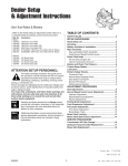
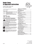
Dealer Setup
& Adjustment Instructions
Zero-Turn Riders & Mowers
TABLE OF CONTENTS:
This Dealer Setup & Adjustment Instruction
covers the following products:
SAFETY RULES .................................................................2
SETUP PROCEDURES
250 Z (Snapper)
Mfg. No. Description
7800158 ERZT20441BVE2, 20HP European Rider with 44” Mower
Quick Setup List ................................................................5
Uncrating ............................................................................6
Battery Activation & Installation ......................................7
Check Fluid levels .............................................................8
Fill and Check Engine Oil.................................................8
Reduce and Check Tire Pressure ....................................8
Torque Mower Blades .......................................................9
Lubrication .........................................................................9
Perform Safety Checks ...................................................10
Functional Tests.............................................................10
Mower Blade Stopping Check........................................10
Seat Switch Connection .................................................10
Burnish PTO Clutch .......................................................10
Safety Interlock System .................................................11
Javelin (Simplicity)
Mfg. No. Description
7800157 EJAV20441BVE2, 20HP European Rider with 44” Mower
ATTENTION SETUP PERSONNEL:
The safety warnings provided in this guide and in
the operator's manual included with the unit contain
important information that must be obeyed when
assembling, setting-up, operating, servicing, transporting, or storing the unit.
These warnings are highlighted by the safety alert triangle symbol shown above, which signifies that an important safety message is being provided.
You must read, understand, and follow these warnings and
instructions, and use safe shop and work practices at all
times while working on or around this unit and all other
outdoor power equipment.
ADJUSTMENT PROCEDURES
Seat Adjustments ............................................................11
Motion Control Lever Adjustment..................................12
Operator Adjustment ......................................................12
Speed Balancing Adjustment .........................................12
Lever Friction Adjustment ..............................................12
Neutral Adjustments.......................................................13
Parking Brake Adjustment..............................................14
Front Suspension Adjustment .......................................14
PTO Clutch Adjustment ..................................................15
PTO Clutch Adjustment .................................................15
Blade Brake Check ........................................................15
Mower Deck Leveling ......................................................16
Roller Bar Leveling ..........................................................17
Sections and items denoted by the Setup symbol
provide the information necessary to fully assemble,
test, and prepare the units described above for
delivery to your customers.
SERVICE PROCEDURES
Additional information concerning functional tests,
general adjustment procedures, and the location of
normal lubrication points are included in these
instructions.
Transmission Drive Belt Replacement ..........................18
Mower Belt Replacement ................................................19
Fuse Replacement ...........................................................19
Form No. 7101168
Revision 00
10/2006
1
TP 300-5241-00-HZ-SN
250 Z & Javelin Series
!
IMPORTANT SAFETY INSTRUCTIONS
!
WARNING: This powerful cutting machine is capable of amputating hands and feet and can throw objects that can cause
injury and damage! Failure to comply with the following SAFETY instructions could result in serious injury or death to
the operator or other persons. The owner of the machine must understand these instructions and must allow only persons who understand these instructions to operate machine. Each person operating the machine must be of sound mind
and body and must not be under the influence of any substance, which might impair vision, dexterity or judgment. If you
have any questions pertaining to your machine which your dealer cannot answer to your satisfaction, call or write the
Customer Service Department at SNAPPER Products Inc., McDonough, Georgia 30253. Phone: (1-800-935-2967).
PROTECTION FOR CHILDREN
PROTECTION AGAINST TIPOVERS
Tragic accidents can occur if the operator is not alert to
the presence of children. Children are often attracted to
the machine and the mowing activity. Children who have
been given rides in the past may suddenly appear in the
mowing area for another ride and be run over or backed
over by the machine. Never assume that children will
remain where you last saw them.
1. KEEP children out of the mowing area and under the watchful care of a responsible adult other than the operator.
2. DO NOT allow children in yard when machine is operated
(even with the blade OFF).
3. DO NOT allow children or others to ride on machine, attachments or towed equipment (even with the blades OFF). They
may fall and be seriously injured.
4. DO NOT allow pre-teenage children to operate machine.
5. ALLOW only responsible adults & teenagers with mature
judgment under close adult supervision to operate machine.
6. DO NOT operate blades in reverse. STOP BLADES. LOOK
and SEE behind and down for children, pets and hazards
before and while backing.
7. USE EXTRA CARE when approaching blind corners, shrubs,
trees, or other objects that may obscure vision.
(Continued From Previous Column)
5. STAY ALERT for holes and other hidden hazards. Tall grass
can hide obstacles. Keep away from ditches, washouts, culverts, fences and protruding objects.
6. KEEP A SAFE DISTANCE (at least 3 feet) away from edge of
ditches and other drop offs. The machine could turn over if
an edge caves in.
7. Always begin forward motion slowly and with caution.
8. Use weights or a weighted load carrier in accordance with
instructions supplied with a grass catcher. DO NOT operate
machine on slopes exceeding 10 degrees (18% grade) when
equipped with grass catcher.
9. DO NOT put your foot on the ground to try to stabilize the
machine.
10. DO NOT operate machine on wet grass. Reduced traction
could cause sliding.
11. Chose a low enough speed setting so that you will not have
to stop or shift on a slope. Tires may lose traction on slopes
even though the brakes are functioning properly.
12. DO NOT operate machine under any condition where traction, steering or stability is doubtful.
13. Always keep the machine in gear when going down slopes.
DO NOT shift to neutral (or actuate hydro roll release) and
coast downhill.
PROTECTION AGAINST TIPOVERS
Slopes are a major factor related to loss-of-control and
tip-over accidents, which can result in severe injury or
death. All slopes require extra CAUTION. If you cannot
back up the slope or if you feel uneasy on the slope, DO
NOT mow it. Use extra care with grass catchers or other
attachments; these affect the handling and the stability of
the machine.
1. DO NOT operate machine on slopes exceeding 10 degrees
(18% grade).
2. Exercise EXTREME CAUTION on slopes. Turn blades OFF
when traveling uphill. Use a slow speed and avoid sudden or
sharp turns.
3. DO NOT operate machine back and forth across face of
slopes. Operate up and down. Practice on slopes with blades
off.
4. AVOID starting, stopping or turning on slopes. If machine
stops going uphill or tires lose traction, turn blades OFF and
back slowly straight down the slope.
TP 300-5241-00-HZ-SN
PREPARATION
1.
2.
3.
4.
5.
2
Read, understand, and follow instructions and warnings in
this manual and on the machine, engine and attachments.
Know the controls and the proper use of the machine before
starting.
Only mature, responsible persons shall operate the machine
and only after proper instruction.
Data indicates that operators age 60 and above, are involved
in a large percentage of mower-related injuries. These operators should evaluate their ability to operate the mower safely
enough to protect themselves and others from serious injury.
Handle fuel with extra care. Fuels are flammable and vapors
are explosive. Use only an approved fuel container. DO NOT
remove fuel cap or add fuel with engine running. Add fuel
outdoors only with engine stopped and cool. Clean spilled
fuel from machine. DO NOT smoke.
Practice operation of machine with BLADES OFF to learn
controls and develop skills.
10/2006
250 Z & Javelin Series
!
IMPORTANT SAFETY INSTRUCTIONS
PREPARATION
OPERATION
(Continued From Previous Page)
6. Check the area to be mowed and remove all objects such as
toys, wire, rocks, limbs and other objects that could cause
injury if thrown by blade or interfere with mowing.
7. Keep people and pets out of mowing area. Immediately STOP
blades, STOP engine, and STOP machine if anyone enters
the area.
8. Check shields, deflectors, switches, blade controls and other
safety devices frequently for proper operation and location.
9. Make sure all safety decals are clearly legible. Replace if
damaged.
10. Protect yourself when mowing and wear safety glasses, long
pants and substantial footwear.
11. Know how to STOP blades and engine quickly in preparation
for emergencies.
12. Use extra care when loading or unloading the machine into a
trailer or truck.
13. Check grass catcher components frequently for signs of
wear or deterioration and replace as needed to prevent injury
from thrown objects going through weak or worn spots.
1.
2.
3.
4.
5.
6.
7.
8.
9.
10.
11.
SAFE HANDLING OF GASOLINE
To avoid personal injury or property damage, use extreme
care in handling gasoline. Gasoline is extremely flammable and the vapors are explosive
1. Extinguish all cigarettes, cigars, pipes and other sources of
ignition.
2. Use only an approved fuel container.
3. DO NOT remove fuel cap or add fuel with the engine running.
Allow the engine to cool before refueling.
4. DO NOT refuel the machine indoors.
5. DO NOT store the machine or fuel container inside where
there is an open flame, spark or pilot light such as on a water
heater or other appliances.
6. DO NOT fill fuel containers inside a vehicle or on a truck or
trailer bed with a plastic liner. Always place the containers on
the ground away from the vehicle before filling.
7. Remove gas-powered equipment from the vehicle or trailer
and refuel it on the ground. If this is not possible, then refuel
equipment using a portable container, rather than a gasoline
dispenser nozzle.
8. DO NOT start gas powered equipment in enclosed vehicles
or trailers.
9. Keep the nozzle in contact with the rim of the fuel tank or
container opening at all times until fueling is complete. DO
NOT use a nozzle lock-open device
10. If fuel is spilled on clothing, change clothing immediately.
11. Never overfill a fuel tank. Replace fuel cap and tighten
securely.
10/2006
12.
13.
14.
15.
16.
17.
18.
3
!
Mount and dismount machine from left side. Keep clear of
discharge opening at all times.
Start engine from operator's seat, if possible. Make sure
blades are OFF and parking brake is set.
DO NOT leave machine with engine running. STOP engine,
STOP blades, SET brake, and Remove key before leaving
operators position of any reason.
DO NOT operate machine unless properly seated with feet on
feet rests or pedal(s).
STOP BLADES and ENGINE and make sure blades have
stopped before removing grass catcher or unclogging mower
to prevent loss of fingers or hand.
Blades must be OFF except when cutting grass. Set blades in
highest position when mowing over rough ground.
Keep hands and feet away from rotating blades underneath
deck. DO NOT place foot on ground while BLADES are ON or
machine is in motion.
DO NOT operate machine without entire grass catcher or
guards in place and working. DO NOT point discharge at people, passing cars, windows or doors.
Slow down before turning.
Watch out for traffic when near or crossing roadways.
STOP engine immediately after striking an obstruction.
Inspect machine and repair damage before resuming operation.
Operate machine only in daylight or with good artificial light.
Move joystick (if equipped) SLOWLY to maintain control during speed and directional changes.
Exercise CAUTION when pulling loads. Limit loads to those
you can safely control and attach loads to hitch plate as
specified with attachment instructions.
On slopes, the weight of the towed equipment may cause
loss of traction and loss of control. When towing, travel slowly and allow extra distance to stop.
DO NOT operate engine in enclosed areas. Engine exhaust
gases contain carbon monoxide, a deadly poison.
DO NOT discharge material against a wall or obstruction.
Material may ricochet back towards the operator.
Only use accessories approved by the manufacturer. See
manufacturer's instructions for proper operation and installation of accessories.
TP 300-5241-00-HZ-SN
250 Z & Javelin Series
IMPORTANT SAFETY INSTRUCTIONS
!
!
TOWING
MAINTENANCE
1.
(Continued From Previous Column)
6. Always provide adequate ventilation when running engine.
Exhaust gases contain carbon monoxide, an odorless and
deadly poison.
7. Disconnect negative (black) cable from battery before performing maintenance or service. Cranking engine could
cause injury.
8. DO NOT work under machine without safety blocks.
9. Service engine and make adjustments only when engine is
stopped. Remove spark plug wire(s) from spark plug(s) and
secure wire(s) away from spark plug(s).
10. DO NOT change engine governor speed settings or overspeed engine.
11. Lubricate machine at intervals specified in manual to prevent
controls from binding.
12. Mower blades are sharp and can cut. Wrap the blades or
wear heavy leather gloves and use CAUTION when handling
them.
13. DO NOT test for spark by grounding spark plug next to spark
plug hole; spark plug could ignite gas exiting engine.
14. Have machine serviced by an authorized dealer at least once
a year and have the dealer install any new safety devices.
15. Maintain or replace safety and instruction labels as necessary.
16. Use only genuine replacement parts to assure that original
standards are maintained.
2.
3.
4.
5.
Tow only with a machine that has a hitch designed for towing. DO NOT attach towed equipment except at the hitch
point.
Follow the manufacturer's recommendation for weight limits
for towed equipment and towing on slopes.
DO NOT allow children or others on towed equipment.
On slopes, the weight of the towed equipment may cause
loss of traction and loss of control.
Travel slowly and allow extra distance to stop.
MAINTENANCE
1.
2.
3.
4.
5.
DO NOT store machine or fuel container inside where fumes
may reach an open flame, spark or pilot light such as in a
water heater, furnace, clothes dryer or other gas appliance.
Allow engine to cool before storing machine in an enclosure.
Store fuel container out of the reach of children in a well ventilated, unoccupied building.
Keep engine free of grass, leaves or excess grease to reduce
fire hazard and engine overheating.
When draining fuel tank, drain fuel into an approved container outdoors and away from open flame.
Check brakes frequently; adjust, repair or replace as needed.
Keep all bolts, nuts and screws properly tight. Check that all
cotter pins are in proper position.
TP 300-5241-00-HZ-SN
4
10/2006
250 Z & Javelin Series
Quick Setup List Page
Setup Procedure
Steps to Perform
6
Uncrating
❏ Remove crate & banding.
❏ Place transmissions in ROLL RELEASE position & roll off
skid.
7
Battery Activation &
Installation
❏ Charge the battery (Note: proceed with other setup steps
while battery is charging).
❏ Install & secure battery.
8
Check Fluid Levels
❏ Fill & check Engine oil level.
❏ Reduce & check tire pressures
(Front tires 25 psi, rear tires 15 psi).
9
Mower Assembly
❏ Torque mower blade hardware.
9
Lubrication
❏ Lubricate all grease & oil points.
10
SAFETY CHECKS
❏ Check for LOOSE HARDWARE.
❏ Check all OPERATOR CONTROLS.
❏ Perform MOWER BLADE STOPPING CHECK.
(Blade must stop within 5 seconds!)
❏ Perform SAFETY INTERLOCK SYSTEM CHECK.
10
Burnish Electric Clutch
❏ Burnish electric clutch (run for 15 seconds, repeat 10 times).
❏ Repeat MOWER BLADE STOPPING CHECK.
(Blade must stop within 5 seconds!)
10/2006
5
TP 300-5241-00-HZ-SN
250 Z & Javelin Series
Uncrating
A
1. Using a reciprocating utility saw or equivalent, cut
crate away from bottom skid. Remove crate. Remove
plastic wrap.
2. Cut any banding securing the unit.
IMPORTANT NOTE
B
When cutting crate from bottom skid,
use caution around tires and mower
rollers.
Figure 1. Roll Release Components (On Each Side)
A. Roll Release Rod
B. Roll Release Plate
3. Place transmissions in the roll release position by
pushing the roll release rods (A, Figure 1), located
under the rear of the unit behind each transmission, in
toward the transmission until the collar on the neck of
each rod passes through the keyhole in the roll
release plate (B). Then lock the rod in the roll release
position by sliding the rod sideways into the keyhole
slot.
5. Be sure there are no nails or sharp objects on the bottom of the skid to puncture the tires. Roll the rider forward off the skid.
6. After moving the rider, move the motion control levers
back into their neutral locked positions, and reengage the transmissions (drive position) by unlocking the roll release rods and pulling them out.
4. Move the motion control levers from their neutral
locked positions.
The rider can now be pushed by hand.
TP 300-5241-00-HZ-SN
6
10/2006
250 Z & Javelin Series
Battery Activation &
Installation
WARNING
BATTERY SAFETY RULES
• Battery acid causes severe burns. Avoid contact
with skin.
• Wear eye protection while handling the battery.
• To avoid an explosion, keep flames and sparks
away from battery, especially while charging.
• When installing battery cables, CONNECT THE
POSITIVE (+) CABLE FIRST and negative (-) cable
last. If not done in this order, the positive
terminal can be shorted to the frame by a tool.
B
C
A
Charge Battery
1. Tip the seat forward to access the battery.
2. Remove the battery from the battery compartment,
and place the battery on a level, non-concrete surface.
Figure 2. Battery
A. Negative Cable
B. Positive Cable & Cover
C. Hold-Down Rod
Note: When removing the battery cables from the battery, always remove the negative (-) cable first.
3. To charge the battery, follow the instructions provided
by the battery charger manufacturer as well as all
warnings included in the safety rules section of this
document. Charge the battery at 6-10 amps for 1
hour. Do not charge at a rate higher than 10 amps.
Install Battery
1. Install the battery in the battery compartment and
secure using the holddown rod (C, Figure 2).
2. Connect the red positive battery cable (B) to the positive battery terminal, then cover the positive battery
terminal with the terminal cover.
3. Connect the black negative battery cable (A) to the
negative battery terminal.
10/2006
7
TP 300-5241-00-HZ-SN
250 Z & Javelin Series
Check
Fluid Levels
Fill & Check Engine Oil
A
Removing the rear cover to gain access to the
engine, use the dipstick (A, Figure 3) to check the
engine oil level. If necessary add engine oil. Check
engine manufacturer’s owner’s manual for oil recommendations.
Figure 3. Check Engine Oil Level
A. Engine Oil Dip Stick
Reduce & Check Tire
Pressures
The tires are over-inflated for shipping purposes. Inflate
to the pressures shown. Note that these pressures may
differ slightly from the “Max Inflation” stamped on the
side-wall of the tires. The pressures shown provide proper traction, improve cut quality, and extend tire life.
Tire
Pressure
Front
25 psi (1,72 bar)
Rear
15 psi (1,03 bar)
Figure 4. Tire Pressures
TP 300-5241-00-HZ-SN
8
10/2006
250 Z & Javelin Series
Torque Mower Blades
WARNING
For your personal safety, blade mounting
hardware must each be installed with two
washers, then securely tightened to noted torque.
1. Check that blades are installed with the tabs pointing
up toward deck as shown in Figure 5. Secure with a
nut, and two blade washers, concave side up. Use a
wooden block to prevent blade rotation and torque nut
to 80-90 ft-lbs.
Figure 5. Blade Installation
A. 4x4 Wood Block
B. Blade Washer (2)
C. Blade Nut
Lubrication
Lubricate the unit at the following lubrication points as
well as those shown in Figure 6.
Generally, all moving metal parts should be oiled where
contact is made with other parts. Keep oil and grease off
belts and pulleys. Remember to wipe fittings and surfaces clean both before and after lubrication.Use grease
fittings when present. Disassemble parts to apply grease
to moving parts when grease fittings are not installed.
Grease:
• front caster wheel axles
• front caster spindle bosses
• front axle center pivot
Not all greases are compatible. Use automotive-type
lithium grease.
• mower deck arbors (blade spindles)*
* Some deck arbors have grease fittings above the
mower deck, while others have grease fittings below the
deck.
• mower deck idler arm
Oil:
• motion control lever pivot points
• discharge chute hinge
• deck lift pivot points
2x
3x
2x
Figure 6. Lubrication Points (Grease)
10/2006
9
TP 300-5241-00-HZ-SN
250 Z & Javelin Series
Perform
Safety Checks
Burnish PTO Clutch
1. Select a safe area to operate the mower deck. With
the motion control levers locked into their neutral
locked positions, the PTO switch disengaged, and an
operator in the seat, start the engine. Run the engine
at full speed.
WARNING
Disengage the PTO, stop the engine, move both
motion control levers into their neutral locked
positions, and wait for moving parts to stop
before leaving operator's position for any reason.
2. Engage the PTO switch and run the deck for fifteen
seconds. Disengage the PTO switch and wait for the
mower drive belt to stop.
3. Repeat step 2 above ten times, and then re-check the
mower blade stopping time. (Stopping time must be
five seconds or less.)
If the unit does not pass the test, do not operate
it. Under no circumstance should you attempt to
defeat the purpose of the safety system.
Functional Tests
1. Check for loose bolts, screws, nuts, etc.
2. Start the engine and check all controls for proper
operation: motion control levers, engine speed and
choke cables, electric PTO clutch, cutting height
adjustment lever, etc.
3. Stop the engine and check for fluid leaks: oil, gasoline, or transmission oil.
4. If any control fails to operate properly during testing or
seems to be out of adjustment, check and readjust it
according to the following Adjustments section.
4. Turn the key to OFF to end the demonstration.
Mower Blade Stopping Check
Mower blades and mower drive belt should come to a
complete stop within five seconds after the electric clutch
switch is turned off.
With the motion control levers locked into their neutral
locked positions, the electric clutch switch disengaged,
and an operator in the seat, start the engine. Run at full
speed. Engage the electric PTO clutch switch and wait
several seconds. Disengage electric clutch switch and
check the time it takes for the mower drive belt to stop. If
the mower drive belt does not stop within five seconds,
adjust the PTO clutch according to the instructions in the
Electric Clutch Adjustment section.
Seat Switch Connection
Check that the seat switch wire harness (C, Figure 7) is
connected to the seat switch.
TP 300-5241-00-HZ-SN
10
10/2006
250 Z & Javelin Series
SAFETY INTERLOCK
SYSTEM
Adjustment
Procedures
This unit is equipped with safety interlock switches.
These safety systems are present for your safety, do
not attempt to bypass safety switches, and never tamper with safety devices. Check their operation regularly.
Seat Adjustments
The seat and motion control levers should be adjusted
so that operator’s elbows are supported by the arm rests
when his/her hands are on the controls, and the motion
control levers can be moved through their full range of
motion without contacting the operator’s legs.
Operational SAFETY Checks
TEST 1 — ENGINE SHOULD NOT CRANK IF:
• PTO switch is engaged, OR
Seat Position Adjustment
• Motion control levers are not locked in their NEUTRAL LOCKED positions.
See Figure 7. The seat can be adjusted forward and
back. Remove the knobs (A), and loosen the support
bolts (B). Slide the seat to the desired position, then
reinstall the knobs and retighten the bolts.
TEST 2 — ENGINE SHOULD CRANK IF:
• PTO switch is NOT engaged, AND
• Motion control levers are locked into their
NEUTRAL LOCKED positions.
TEST 3 — ENGINE SHOULD SHUT OFF IF:
• Operator rises off seat with PTO engaged, OR
A
• Operator rises off seat with motion control levers
not locked in their neutral locked positions, OR
B
• With operator seated, right motion control lever is
moved out of its neutral locked position before left
motion control lever.
C
TEST 4 — BLADE BRAKE CHECK
The mower blades and mower drive belt should come
to a complete stop within five seconds after the electric
PTO switch is turned off (or operator rises off seat). If
mower drive belt does not stop within five seconds, see
your dealer.
NOTE: Once the engine has stopped, the PTO switch
must be turned off, and the motion control levers must
be locked in their NEUTRAL LOCKED positions in
order to start the engine.
Figure 7. Seat Adjustment
A. Adjustment Knobs
B. Support Bolts
C. Seat Switch Wire Harness
WARNING
If the unit does not pass a safety test, do not
operate it. See your authorized dealer. Under no
circumstance should you attempt to defeat the
purpose of the safety interlock system.
10/2006
11
TP 300-5241-00-HZ-SN
250 Z & Javelin Series
Motion Control Lever
Adjustment
Operator Adjustment
A
The motion control levers can be adjusted in two ways.
The placement of the levers (how close the ends are to
one another) and the height of the levers can be adjusted.
To Adjust the Lever Placement: Loosen the two bolts
(B, Figure 8) securing the control track, and adjust the
control track in or out to properly adjust the lever end
spacing.
Note: The bottom bolt may be accessed from beneath
the fender.
C
B
Figure 8. Motion Control Lever Adjustments
A. Lever Height Adjustment Hardware
B. Lever Placement Adjustment Hardware
C. Forward Adjust Plate
To Adjust the Handle Height: Remove the motion control lever mounting hardware (A, Figure 8) and reposition
the lever either up or down from its original position. You
may need to readjust the handle placement as described
above.
WARNING
DO NOT adjust the rider for a faster overall speed
forward or reverse than it was designed for.
Speed Balancing Adjustment
If the rider drifts to the right or left when the motion control levers are in the maximum forward position, the top
speed of each of these levers can be balanced. Only
adjust the speed of the wheel that is traveling faster.
To Reduce the Speed of the Faster Wheel:
1. Loosen the two bolts securing the forward adjust
plate (C, Figure 8).
2. Slide the plate up approximately 1/8”.
B
3. Retighten the bolts and recheck speed balance.
4. Repeat steps 1-3 until adjustment is complete.
C
Lever Friction Adjustment
The motion control levers should be tight when moving in
and out of their neutral locked positions. If the levers are
loose, the lever friction should be adjusted.
A
To adjust friction:
D
Tighten the nyloc nut (C, Figure 9) securing the motion
control lever (A) to the control bracket (B) against the
nylon washer (D).
Note: The control bracket is located beneath the fender
next to the operator’s seat.
TP 300-5241-00-HZ-SN
Figure 9. Motion Control Lever Friction Adjustment
A. Motion Control Lever
B. Control Bracket
C. Nyloc Nut
D. Nylon Washer
12
10/2006
250 Z & Javelin Series
Neutral Adjustments
If the machine creeps while the motion control levers are
locked into their neutral locked positions, then it may be
necessary to adjust the link rods.
A
Perform this adjustment on a hard level surface such as
a concrete floor.
IMPORTANT NOTE: This adjustment should be performed with the engine OFF. Perform the adjustment,
then start the engine to check the adjustment. If further
adjustment is required, stop the engine before performing the adjustment.
C
B
1. Determine which wheel is creeping. The left side
transmission and link rod control the left wheel, the
right link rod controls the right wheel.
D
E
F
2. Disengage the PTO, lock the motion control levers
into their neutral locked positions, turn the engine off,
remove the key, and wait for all moving parts to stop.
G
Figure 10. Neutral Adjustment (Right Side Shown)
A. Control Bracket
B. Rod End
C. Rod End Connecting Hardware
D. Jam Nut
E. Link Rod
F. Compression Spring
G. Spring Adjustment Nuts (2)
3. Remove the hardware (C, Figure 10) connecting the
rod end (B) to the control bracket (A).
Note: The rod end is located under the fender beside
the operator seat.
4. Loosen the rod end jam nut (D).
If the transmission is creeping forward, turn the rod
end in (clockwise) one or two turns to shorten the link
rod (E).
into its neutral locked position with little or no additional forward movement.
If the transmission is creeping in reverse, turn the rod
end out (counterclockwise) one to two turns to lengthen the link rod.
c. If additional rearward movement is required,
increase the length of the compression spring set in
step a by 1/16 - 1/8”. If additional forward movement
is required, decrease the length of the compression
spring by 1/16 - 1/8”. Recheck operation. Repeat as
needed.
5. Retighten the jam nut, and reconnect the rod end to
the control bracket.
6. Start the unit and check for transmission creep.
Repeat steps 2-5 if necessary.
NOTE: If equal amounts of forward and rearward
movement are required, do not adjust the spring.
7. Once the correct adjustment is achieved, check operation of the neutral return system:
d. Repeat steps a through c for left motion control
lever.
a. With the right motion control lever in its neutral
locked position, and the engine stopped, check the
length of the compression spring (F). The length of
the compression spring should initially be set to 25/16”. Turn the two adjustment nuts (G) in or out until
the desired measurement is achieved.
b. With the engine stopped, move the lever from its
neutral locked position into neutral, then from neutral
into the forward position. Release the lever. The
lever should swiftly return to the neutral position and
be able to be moved out into its neutral locked position with little or no additional rearward movement.
Now move the lever from neutral into the reverse
position and release. The lever should swiftly return
to the neutral position and be able to be moved out
10/2006
13
TP 300-5241-00-HZ-SN
250 Z & Javelin Series
Parking Brake
Adjustment
D
E
1. Disengage the PTO, stop the engine, block the front
wheels, remove the ignition key, and lock the motion
control levers into their neutral lock positions.
F
2. Elevate the rear end of the unit, making sure it is
safely supported.
C
3. Before attempting brake adjustment, check the brake
gear (A, Figure 11), brake arm (B), park brake bracket (D), brake rod (E), and compression spring (F) for
dirt or debris that may affect brake operation.
4. Check to see that the brake arms (B) are engaged
against the brake gears (A), with the teeth on the
arms meshing with the teeth on the gears.
Note: The rear wheels may need to be moved slightly
for the teeth to mesh properly.
5. With the parking brake engaged (motion control
levers moved into their neutral locked positions),
measure the length of the compression spring (F).
The measurement should be between 2-1/2” and 23/4”. If not, tighten or loosen the brake rod adjustment nut (C) until the correct measurement is
achieved.
A
B
Figure 11. Parking Brake Adjustment
A. Brake Gear (One Each Side)
B. Brake Arm (One Each Side)
C. Brake Rod Adjustment Nut
D. Park Brake Bracket
E. Park Brake Rod
F. Compression Spring
Front Suspension
Adjustment
INCREASE
(Select Models)
DECREASE
A
The shock assembly can be adjusted to vary the amount
of pre-load applied to the springs. This allows the operator to customize the ride according to operator’s weight
and operating conditions.
LESS PRE-LOAD:
• Light operator weight
• Softer, more cushioned ride
• Best for relatively flat terrain
MORE PRE-LOAD:
• Heavy operator weight
Figure 12. Front Suspension Adjustment
A. Pre-Load Adjustment Collar
• Stiffer, more rigid ride
• Better handling and greater stability on hilly terrain
2. See Figure 12. Turn the pre-load adjustment collar
(A) CLOCKWISE to increase the pre-load, turn
COUNTER-CLOCKWISE to decrease the pre-load.
Make sure both shocks are set to the same amount of
pre-load.
TO ADJUST THE SPRING PRE-LOAD:
1. Park machine on a flat, level surface. Disengage the
PTO, stop the engine and engage the parking brake.
3. Secure the set collar by placing the rubber o-ring
against it.
TP 300-5241-00-HZ-SN
14
10/2006
250 Z & Javelin Series
A
B
B
B
C
B
Figure 14. Adjust PTO Clutch
A. Window
B. Adjustment Nut
C. .016”-.018” (0,40-0,45mm) Feeler Gauge
A
Figure 13. PTO Clutch Adjustment
A. Adjustment Window (Qty. 3, one shown)
B. Adjustment Nut
PTO Clutch Adjustment
WARNING
To avoid serious injury, perform adjustments only
with engine stopped, key removed and rider on
level ground.
Check the PTO clutch adjustment after the initial 25 hour
break-in period and then after every 250 hours of operation. Also perform the following procedure if the clutch is
slipping or will not engage, or if a new clutch has been
installed.
Blade Brake Check
1. Remove key from ignition switch and disconnect
spark plug wires to prevent the possibility of accidental starting while the PTO is being adjusted.
Mower blades and mower drive belt should come to a
complete stop within five seconds after electric PTO
switch is turned off.
2. See Figure 13. Note the position of the 3 adjustment
windows (A) in the side of the brake plate and the
nylock adjustment nuts (B).
1. With parking brake engaged, PTO disengaged and
an operator in the seat, start the engine.
3. Insert a .016”-.018” (0,40-0,45mm) feeler gauge (C)
through each window, positioning the gauge between
the rotor face and the armature face as shown in
Figure 14.
2. Have an assistant observe the mower drive belt
through the opening between the frame and top of
mower deck. Engage the PTO and wait several seconds. Disengage the PTO and check the amount of
time it takes for the mower drive belt to stop.
4. Alternately tighten the adjustment nuts (B, Figure 13)
until the rotor face and armature face just contacts
the gauge.
3. If the mower drive belt does not stop within five seconds, perform the PTO Clutch Adjustment. If the belt
still does not stop within 5 seconds, replace the
clutch.
5. Check the windows for an equal amount of tension
when the gauge is inserted and removed, and make
any necessary adjustments by tightening or loosening the adjustment nuts.
NOTE: The actual air gap between the rotor and armature may vary even after performing the adjustment procedure. This is due to dimensional variations on component parts, and is an acceptable condition.
6. Check the mower blade stopping time. The mower
blades and mower drive belt should come to a complete stop within five seconds after the electric PTO
switch is turned off.
10/2006
15
TP 300-5241-00-HZ-SN
250 Z & Javelin Series
A
B
C
Figure 15. Orient Blades Side-to-Side
Mower Deck Leveling
Figure 16. Measure Blade Tips to Ground
A. Mower Deck
C. Level Ground
B. Blade Tip
Perform these adjustments on a flat level surface. Be
sure to check and adjust tire pressures before leveling
the mower deck
SIDE-TO-SIDE LEVELING
1. With the mower installed, place the rider on a
smooth, level surface such as a concrete floor. Turn
the front wheels so they are straight.
2. Check for bent blades and replace if necessary.
3. Place the mower cutting height lever in the fourth
adjustment notch from the bottom. Arrange the outside mower blades so that they are pointing from
side-to-side (Figure 15).
4. Measure the distance between the outside tips of
each blade and the ground (Figures 15 & 16). The
measurement should be 3” (7,6 cm), +/-1/8” (3mm).
If there is more than 1/8” (3mm) difference between
the measurements on each side, proceed to step 5. If
the difference is 1/8” (3mm) or less, proceed to step
6.
A
Figure 17. Mower Leveling - Side-to-Side
A. Rear Leveling Nuts
(Left side shown, right side hidden)
5. Use the rear leveling nuts (A, Figure 17) to adjust the
side-to-side leveling of the deck. Repeat step 4 if
necessary.
FRONT-TO-BACK LEVELING
6. Arrange the blades so they face front-to-back (Figure
18).
7. Measure the distance from the ground to the front tip
of the center blade and from the ground to the rear
tips of the rear blades (Figures 16 & 18). The front
tip of the center blade should be 1/4" (6mm) higher
than the rear tips of the rear blades. If not, proceed
with steps 8 - 9.
Figure 18. Orient Blades Front-to-Back
(Continued Next Page)
TP 300-5241-00-HZ-SN
16
10/2006
250 Z & Javelin Series
8. To adjust the front of the mower deck, use the adjusting nuts on the front deck lift rods (A, Figure 19) until
the desired measurement is achieved. Be sure to
adjust both sides the same amount.
9. Re-check the blade measurement then repeat steps
7 - 9 as necessary.
A
Figure 19. Mower Leveling - Front-to-Back
A. Front Leveling Nuts
ROLLER BAR LEVELING
(If Equipped)
1. First level the mower deck using the procedure found
in MOWER DECK LEVELING.
2. With the mower installed, place the rider on a
smooth, level surface such as a concrete floor. Turn
the front wheels so they are straight.
A
3. Place the cutting height adjustment lever in the top
adjustment notch.
4. Measure the distance between the outside ends of
the roller bar and the ground. If there is more than
1/8” (3mm) difference between the measurements on
each side, proceed to step 5.
5. Locate the roller bar leveling hardware on the right
side of the mower deck (A, Figure 20). Loosen the
hardware and raise or lower the roller bar until the
correct level is achieved, then tighten the hardware.
Repeat steps 4 & 5 if necessary.
10/2006
Figure 20. Roller Bar Leveling
A. Leveling Hardware
17
TP 300-5241-00-HZ-SN
250 Z & Javelin Series
TRANSMISSION DRIVE BELT
REPLACEMENT
E
To avoid damaging belts, DO NOT
PRY BELTS OVER PULLEYS.
C
F
C
1. Park the rider on a smooth, level surface such as a
concrete floor. Disengage the PTO, lock the motion
control levers into their neutral locked positions, turn
off the engine, and remove the ignition key.
D
2. Remove the mower belt from the PTO pulley (see
MOWER BELT REPLACEMENT for instructions).
FRONT
3. Relieve tension on the transmission belt (A, Figure
21) by moving the idler arm (E) in the direction indicated by the curved arrow, and remove the old belt
from the crankshaft and transmission pulleys.
4. Loosen (do not remove) the anti-rotation bracket
hardware (C, Figure 22), and slip the old belt out
between the anti-rotation pin (B) and the PTO (A).
Note: The PTO wiring harness must be disconnected
from the main wiring harness in order to remove and
replace the transmission belt. Be sure to reconnect the
harness after the belt is replaced.
5. Reversing steps 3-4, install the new belt, following
the routing in Figure 24. Make sure the V-side of the
belt runs in the grooves of the crankshaft pulley and
transmission pulleys (B & C). Also, make sure that
the anti-rotation pin (B, Figure 22) is inserted into the
anti-rotation slot on the PTO before tightening hardware (C).
A
B
Figure 21. Transmission Drive Belt Replacement
(Shown from Below; Components Removed for
Clarity)
A. Transmission Drive Belt
B. Crankshaft Pulley
C. Transmission Pulley (2)
D. Idler Pulley
E. Idler Arm
F. Idler Tension Spring
6. Reinstall the PTO drive belt.
C
B
A
Figure 22. Anti-Rotation Bracket
(View Looking Back from Mower Deck)
A. PTO Clutch
B. Anti-Rotation Pin
C. Anti-Rotation Bracket Hardware
TP 300-5241-00-HZ-SN
18
10/2006
250 Z & Javelin Series
MOWER BELT REPLACEMENT
D
C
To avoid damaging belts, DO NOT
PRY BELTS OVER PULLEYS.
B
44” Decks:
E
1. Park the rider on a smooth, level surface such as a
concrete floor. Disengage the PTO, lock the motion
control levers into their neutral locked positions, turn
off the engine, and remove the ignition key.
A
2. Remove the hardware (B, Figure 24) securing the
belt guards (A) to the mower deck, and remove the
guards.
Figure 23. Mower Belt Routing - 44” Decks
A. Right Arbor Pulley
B. Left / Center Arbor Pulley
C. PTO Pulley
D. Stationary Idler
E. Belt Tensioning Idler
3. Raise the mower deck to its highest cutting position.
4. Pull back firmly on the belt tensioning idler (E, Figure
23) in the direction indicated, and remove the belt
from the left arbor pulley (A).
5. Remove the old belt from the remaining pulleys.
6. Reversing steps 4 - 5, install the new belt, following
the routing in Figure 23. Be sure to replace the belt
guards.
A
B
Figure 24. Belt Guard Removal
A. Belt Guard (Left side shown, right side similar)
B. Securing Hardware
FUSE REPLACEMENT
1. Park the rider on a smooth, level surface such as a
concrete floor. Disengage the PTO, lock the motion
control levers into their neutral locked positions, turn
off the engine, and remove the ignition key.
A
2. Raise the seat. The fuse block is located on the right
side of the rear seat support.
B
3. Remove and check the suspected fuse (or fuses). If
blown, replace with a fuse with a rating equal to the
ratings indicated in Figure 25.
Figure 25. Fuse Designations and Ratings
A. Accessory - 30 Amp
B. Start - 15 Amp
WARNING
Do not use a fuse with a rating other than that
specified. Serious equipment damage may result.
10/2006
19
TP 300-5241-00-HZ-SN
PRODUCTS, INC.
McDonough, GA., 30253
www.snapper.com
MANUFACTURING, INC.
500 N Spring Street / PO Box 997
Port Washington, WI 53074-0997 USA
www.simplicitymfg.com
Briggs & Stratton Yard Power Products Group
Copyright © 2006, Briggs & Stratton Corporation
Milwaukee, WI, USA. All Rights Reserved