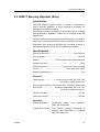
1
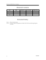
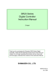
INSTALLATION MANUAL
Robertson RGC12
Gyro Compass
20220737
NOTE!
Simrad Robertson AS makes every effort to ensure that the information
contained within this document is correct. However, our equipment is
continuously being improved and updated, so we cannot assume liability
for any errors which may occur.
The information contained within this document remains the sole property
of Simrad Robertson AS. No part of this document may be copied or
reproduced in any form or by any means, and the information contained
within is not to be passed on to a third party, without the prior written
consent of Simrad Robertson AS.
Warning
The equipment to which this manual applies must only be used for
the purpose for which it was designed. Improper use or
maintenance may cause damage to the equipment or injury to
personnel. The user must be familiar with the contents of the
appropriate manuals before attempting to operate or work on the
equipment.
Simrad Robertson AS disclaims any responsibility for damage or
injury caused by improper installation, use or maintenance of the
equipment.
Simrad Robertson AS
Nyåskaien
P.O. Box 55
N-4379 Egersund, Norway
Telephone:
Telefax:
+47 51 46 20 00
+47 51 46 20 01
Installation Manual
Installation Manual
RGC12 Gyro Compass
This document describes the installation of the Simrad
Robertson RGC12 Gyro Compass and optional
equipment.
20220737B
1
Robertson RGC12 Gyro Compass
Document revisions
Rev
Date
Written by
Checked by
Approved by
A
04.01.2000
NG
VP
ThH
B
04.10.2000
NG
TR
C
D
Document history
Rev. A This is the first issue
Rev. B
2
Section 5 Optional Equipment included. RGC12 External Wiring Diagram
included.
20220737B
Installation Manual
Contents
1
INTRODUCTION ........................................................................................................... 5
2
SPECIFICATIONS .......................................................................................................... 6
2.1 RGC12 Master Compass ........................................................................................ 6
Physical Dimensions .............................................................................................. 6
Power ....................................................................................................................... 6
Accuracy .................................................................................................................. 6
Environmental specifications................................................................................ 6
2.2
RGC12 Control Box ................................................................................................ 7
Physical Dimensions .............................................................................................. 7
Power ....................................................................................................................... 7
General specifications ............................................................................................ 7
Special specifications (option) ............................................................................ 10
Environmental specifications.............................................................................. 10
2.3
3
Cables ..................................................................................................................... 11
INSTALLATION ........................................................................................................... 12
3.1 General information............................................................................................. 12
3.2
Precaution before installation ............................................................................. 12
3.3
3.4
Logistics ................................................................................................................. 13
Terminal connector tool ...................................................................................... 13
3.5
Caution in Installation ......................................................................................... 13
3.6
3.7
100/110V AC Mains .............................................................................................. 15
Spare parts............................................................................................................. 16
4
INSTALLATION DRAWINGS................................................................................... 17
5
OPTIONAL EQUIPMENT ........................................................................................... 23
5.1 DR75 Digital Repeater (NMEA).......................................................................... 23
Introduction .......................................................................................................... 23
Specifications ........................................................................................................ 23
Installation............................................................................................................. 24
Controls ................................................................................................................. 26
Indicators............................................................................................................... 27
Modes..................................................................................................................... 27
5.2
Flashing LCD display .......................................................................................... 27
RSR68 Steering Repeater (Step).......................................................................... 28
20220737B
3
Robertson RGC12 Gyro Compass
Introduction .......................................................................................................... 28
Specifications ........................................................................................................ 28
Installation............................................................................................................. 29
5.3
RSR77 Steering Repeater (Step).......................................................................... 31
Introduction .......................................................................................................... 31
Specifications ........................................................................................................ 31
Installation............................................................................................................. 32
5.4
RP-41-1 Bearing Repeater.................................................................................... 34
Specifications ........................................................................................................ 34
MB Repeater Holder ............................................................................................ 35
BH Repeater Stand............................................................................................... 36
Bearing Repeater Connection............................................................................. 37
5.5
Change Over Unit ................................................................................................ 38
Specifications ........................................................................................................ 38
4
20220737B
Installation Manual
1 INTRODUCTION
This document describes the installation of the Robertson
RGC12 Gyro Compass.
The compass consists of the Master Compass with Sensitive
Element and Control Box.
The gyrocompass RGC12 is a system to detect and display true
heading necessary for navigation and output data to external
equipment. It has been designed for medium and large vessels
and provides high accuracy and reliability on the basis of the
TG-5000 series gyrocompass which has been installed on more
than 5000 vessels.
The Control Box contains all interfaces to external equipment, as
well as connection to the Master Compass. Power for the gyro
system is also terminated in the unit.
Note !
The guidelines for installation presented here must be regarded as a
base for detailed plans prepared by the installation shipyard. These
plans must include drawings, instructions and procedures specific to
the ship in which the equipment is to be installed. These drawings must
be approved by the local maritime classification society.
Simrad Robertson AS accepts no responsibility for any damage
or injury to the system, ship or personnel caused by drawings,
instructions or procedures not prepared by Simrad Robertson
AS.
20220737B
5
Robertson RGC12 Gyro Compass
2 SPECIFICATIONS
2.1 RGC12 Master Compass
Physical Dimensions
Height:......................................................................... 432 mm (17,0”)
Width:.......................................................................... 360 mm (14,2”)
Depth:.......................................................................... 358 mm (14,1”)
Weight: ........................................................................... 25 kg (55 lbs)
Power
Voltage input:........................................Supplied from Control Box
Accuracy
Settling time:..Within 4 hours
(at lat. 35° when starting from deviation angle of
within 30°)
Within 2 hours
(at lat. 35° when starting from deviation angle of
within 5°)
Settle point error: .............................................. ±0.3º x sec. latitude
Standard deviation: ..............................................0.1º x sec. latitude
Repeatability:.±0.2°x sec. latitude
Roll and pitch error: ..........................................±0.5° x sec. latitude
Accuracy for environmental change: ..............±0.5° x sec. latitude
Speed error correction accuracy ....................... ±0.2 x sec. latitude
Environmental specifications
Enclosure material: ..........................................................Aluminium
Enclosure protection: .................................................................. IP22
Operational temperature range:.................................–10°C to 50°C
Storage temperature range:.........................................–25°C to 70°C
Maximum storage period: (recommended temp. +5 - +35°C) 1 year
With reference to the Kongsberg Simrad Environmental
Specification, the following exceptions and additions comply:
IEC Publication: 68-2-1
6
ref. EN 60945
20220737B
Installation Manual
68-2-2
ref. EN 60945
68-2-6
ref. EN 60945
68-2-27 Not tested.
68-2-30 ref. EN 60945
68-2-32 Not applicable ref. EN 60945
68-2-52 ref. EN 60945
157-1
Note !
Not tested
The equipment is approved according to the European Marine
Directive 96/98/EC (Wheel mark) which incorporates the European
Norm EN 60945 (IEC 945 3rd revision).
2.2 RGC12 Control Box
Physical Dimensions
Height:......................................................................... 570 mm (22,4”)
Width:.......................................................................... 334 mm (13,1”)
Depth:............................................................................ 182 mm (7,2”)
Weight: ......................................................................16,5 kg (36,3 lbs)
Power
Voltage input:................. 100/110/220 VAC, single phase, 50/60 Hz
Power consumption: ............................................. 140 VA (Starting)
70 VA (Running)
Emergency power supply:.................................................... 24 VDC
140 W (Starting)
70 W (Running)
General specifications
Repeater type: .................. Step-motor type (24VDC 1 step = 1/6°)
Number of repeater ports:................................................................ 9
(also possible to connect load of max
24V DC 8.5A)
Follow up rate (master compass):.................. 30°/sec. (360°/12 sec.)
Angular freedom of gimbal: ........................ ±45° for roll and pitch
Latitude error correction:.................................... Automatic 0° ∼ 70°
20220737B
7
Robertson RGC12 Gyro Compass
Speed error correction: .............. Automatic
(200 pulse/mile is input)
(GPS input)
or manual
0 ~ 50 Knots settable
Only the repeater compasses
are corrected
Speed input signal: ....................................................... Pulse signal
(200 pulses/nm dry contact point) or GPS.
Digital output - 1
Serial signal ports:.............................................................................. 8
Electrical specification: ........................................ RS422/NMEA0183
Baud rate:....... ..........................................................4800 bits/second
Data length: ... ............................................................................. 8 bits
Parity: ............. ............................................................................ None
Stop bit: .......... ...............................................................................1 bit
Transmission rate:..........................................................1x/5x second
Output format:
$HEHDT, xxx. x, T*hh<CR><LF>
True heading (degree)
$HEROT, –xxx. x, A*hh<CR><LF>
Turning rate
Turning direction: CW (space), CCW (–)
$PTKM, HEALM, xxx. x, *hh<CR><LF>
Alarm group
Appears every 2 seconds.
Digital output - 2
Serial signal ports:.............................................................................. 4
Electrical specification: .................... RS422 (Tokimec specification)
Baud rate:....... ..........................................................9600 bits/second
Data length: ... ............................................................................. 8 bits
Parity: ............. ............................................................................ None
Stop bit: .......... ...............................................................................1 bit
8
20220737B
Installation Manual
Transmission rate:........................................... 50 msec (20x/second)
Output format:
STXKxxx. x, Lxx. x, R–xxx. xETX
True rate
Turning direction: CW (space)
CCW (–)
Speed L=Log
P=GPS
M=Manual
True heading
$PTKM, HEALM, XYYY, Z*hh <or><LF> (every 2 sec.)
Checksum
Alarm group
Analogue signal – 1
Turn rate ports: .................................................................................. 3
–5 to +5 V (±30°/min) + --- CW turn
– --- CCW turn
Analogue signal – 2
Turn rate scale-over ports:................................................................ 3
±30°/min or more ±5 V
+ --- CW turn
– --- CCW turn
GPS input signal (for latitude, speed signals)
Serial signal port: ............................................................................... 1
Electrical specification:......................... RS422/NMEA0183
The Tokimec specifications are as follows:
Baud rate: ..................................................4800 bits/second
Data length:.................................................................. 8 bits
Parity: ........................................................................... None
Stop bit:...........................................................................1 bit
Transmission rate: ........................................................1 sec
20220737B
9
Robertson RGC12 Gyro Compass
Input format:
$GPGLL, xxxx.xx, Nxxxxx.xx, E*hh<CR><LF>
Latitude Longitude
$GPVTG, xxx, T, xxx, M, xx.x,N,*hh<CR><LF>
Heading (COG), Speed (SOG)
Special specifications (option)
Repeater backup signal
24 VDC 1/6° step
3 circuits max. 2.5 A.
Optional output signals
ADD PCB
Additional 6 ports 24V DC stepper output
OPS PCB
Additional 2 ports 35 VDC stepper output
(OPS PCB can not be installed if an ADD PCB is installed.)
Environmental specifications
Enclosure material: ..........................................................Aluminium
Enclosure protection: .................................................................. IP22
Operational temperature range:.................................–10°C to 50°C
Storage temperature range:.........................................–25°C to 70°C
With reference to the Kongsberg Simrad Environmental
Specification, the following exceptions and additions comply:
IEC Publication: 68-2-1
ref. EN 60945
68-2-3
ref. EN 60945
68-2-6 ref. EN 60945
68-2-28 Not tested.
68-2-30 ref. EN 60945
68-2-33 Not applicable ref. EN 60945
68-2-53 ref. EN 60945
157-1
Note !
10
Not tested
The equipment is approved according to the European Marine
Directive 96/98/EC (Wheel mark) which incorporates the European
Norm EN 60945 (IEC 945 3rd revision).
20220737B
Installation Manual
2.3 Cables
No cables are included with the RGC12 delivery.
See Figure 4-5 for cable connections.
Check with supplied cable drawings.
Note !
Cable
no.
1
2
3
4
5
6
Minimum conductor
requirement - mm2
2 x 1.5 + E
AWG15
2 x 1.5
AWG15
2 x 0.5
AWG20
2 x 1.5
AWG15
3 x 0.5
AWG20
4 x 0.5
AWG20
Type of cable
or equivalent
RCOP
RCOP
RCOP
RCOP
RCOP
RCOP
Maximum
cable length
1 km
13 m
13 m
13 m
Remarks
Shielded
Shielded
Shielded
Shielded
Shielded
Cable Specification List (Ref. Figure 4-5)
20220737B
11
Robertson RGC12 Gyro Compass
3 INSTALLATION
3.1 General information
The RGC12 Gyro Compass, part no. 44166585, is shipped in a
cardboard container that includes the following parts:
•
RGC12 Master Compass
P/N 44174001
•
RGC12 Master Compass Sensitive Element
P/N 44174019
•
RGC12 Control Box
P/N 44174027
•
Spare Part and Tool Box
•
RGC12 Instruction Manual
P/N 20220679
•
RGC12 Installation Manual
P/N 20220737
•
Warranty Card
If optional PCBs have been ordered, they are mounted in the
RGC12 Master Compass before shipment. (Refer to Packing
List).
3.2 Precaution before installation
For details of equipment dimensions and layout, see Figure 4-1 Figure 4-4.
The Sensitive Element is packed in foaming styrol, for
protection against vibration and shock, in a separate package.
Caution !
Only people authorized by Simrad or Kongsberg Simrad should
mount the Sensitive Element in the Master Compass.
Make sure that the delivered equipment is free from damage
before starting the installation. Check:
12
1.
Model of equipment
2.
Ship’s power supply
20220737B
Installation Manual
3.3 Logistics
Safety: Refer to general safety procedures
Personal qualifications: Trained mechanical workers
Minimum number of personnel: 1
Ship location: No recommendations
Special tools required:
Terminal connector tool supplied
with equipment
3.4 Terminal connector tool
All terminal connections are by self locking crimp terminals.
A special connector tool is located in a plastic bag inside the
Control Box.
Insert the tool such that the hook enters the slot above the cable
entry. Press down the shaft to open the wire lock mechanism
and insert the wire. Release the pressure and lift out the tool.
The wire is now locked and secured.
3.5 Caution in Installation
20220737B
1.
Install the RGC12 Master Compass so that horizontal base
datum lines coincides with the ship’s fore and aft line. See
Figure 4-1, page 17.
2.
Ensure that the service space shown in the installation
drawing is provided. See Figure 4-2, page 18.
3.
Install the RGC12 Control Box at a convenient place easy
to operate and easy to access for inspection and service.
4.
Since the spring-pressure type terminal boards are
applied in the Control Box for cable connections, do not
connect several wires to one terminal.
13
Robertson RGC12 Gyro Compass
14
5.
The safe distance for magnetic compass is clearly shown
on each unit. Install units in accordance with these safe
distances.
6.
Be sure to install the recommended cables separated
according to the function of each cable, as shown by
separate cable list or inter unit wiring diagram (see Figure
4-5, page 21).
7.
Be sure to install all the equipment cable more than 5 m
away from radio equipment feeders if possible.
8.
Connect terminals marked with
to the ground
terminals of the ship. Shield end of shield cable is to be
finished close to the terminal board and connect to the
ground terminals of the ship.
9.
Armour of cable end for the master compass should be
finished 20~30 mm before the cable entrance for easy
connecting to terminals.
10.
Since semiconductor elements are used in the equipment.
do not use a megger for any test.
11.
Any shipyard that installs this equipment for the first
time should be given instructions by Simrad or
Kongsberg Simrad service engineers.
20220737B
Installation Manual
3.6 100/110V AC Mains
The Gyrocompass is pre-wired for connection to 220V AC
Mains. If the Gyrocompass is connected to 100/110V AC Mains
the following jumpers must be connected in the Control Box.
Refer to Figure 3-1.
1. On the Power PCB connect the Jumper J1.
2. On the Term PCB connect the Jumper J3.
CONTROL BOX
POWER PCB
J1
TERM PCB
Make a jumper at
J1 and J3 when
connecting to
100/110V AC
J3
OPT PCB
Figure 3-1 Jumper connection for 100/110V AC Mains supply
20220737B
15
Robertson RGC12 Gyro Compass
3.7 Spare parts
The Spare Part and Tool Box contains the following:
Item no.
Name of part
Quantity
For Master Compass
1
Fuse 250V, 15A (32x6mm)
2
For Control Box
2
Fuse 125V, 20A (32x6mm)
2
3
Fuse 250V, 6,3A (32x6mm)
2
4
Fuse 125V, 1A (20x5mm)
18
5
Terminal connector tool
1
For Control Box, Optional Board
6
16
Fuse 125V, 1A (20x5mm)
12
20220737B
Installation Manual
4 INSTALLATION DRAWINGS
358 mm
Top view
360 mm
Front view
Right side
432 mm
328 mm
Aft datum line
Figure 4-1 Master Compass Dimensions
20220737B
17
Robertson RGC12 Gyro Compass
Figure 4-2 Master Compass Installation outline
18
20220737B
570 mm
Installation Manual
334 mm
182 mm
Figure 4-3 Control Box Dimensions
20220737B
19
Robertson RGC12 Gyro Compass
Figure 4-4 Control Box Installation outline
20
20220737B
Installation Manual
Figure 4-5 RGC12 Inter Unit Wiring Diagram (N3-082190)
20220737B
21
Robertson RGC12 Gyro Compass
Figure 4-6 RGC12 External Wiring Diagram (N3-082093C)
22
20220737B
Installation Manual
5 OPTIONAL EQUIPMENT
5.1 DR75 Digital Repeater (NMEA)
Introduction
DR75 is a four digit, digital heading repeater. It is powered from
24 VDC, which is derived from the ships supply. Power
consumption is low typically 10 watts.
The display gives a resolution and an accuracy to one tenth of a
degree. The display is visible to three meters over an arc of
ninety degrees from its centre.
The repeater can either be console mounted or bulkhead
mounted with its supplied trunnion bracket.
The internal components are housed in a robust splashproof
aluminium enclosure.
In addition to the heading display this repeater has an
additional display which can be used to indicate rate of turn or
to indicate the desired course to be steered. These features are
selectable by buttons on the front.
Specifications
Overall Dimensions
Height:....................................................................................... 97 mm
With: ........................................................................................ 192 mm
Depth: …37 mm (110 mm allowing for plug and cable clearance)
Weight (nominal):......................................................................1.2 kg
Mounting options: ...............................................Panel or Bulkhead
Finish: ............................... Light Weather-work Grey (BS3816-676)
Construction:............................................. Aluminium splash proof
Compass safe distance: .................................................................2 m
Electrical
Power supply: ......................................................... 24 VDC 10 watts
Data input:......................................... $HEHDTXXX.X<CR><LF>
20220737B
23
Robertson RGC12 Gyro Compass
Operational Features
Dynamic performance:
The Display has a resolution of one tenth of a degree and will
retain alignment for rates in excess of 12 degrees per second.
Environmental specifications
Splash proof to: ............................................................................ IP33
Temperature:.................................................................-15°C to 45°C
Humidity:.............................................................. 0% to 95% at 40°C
Vibration: ..............................................................1-12.5 Hz ±1.6 mm
12.5 – 25 Hz ±0.38 mm
25HZ – 50 Hz ±0.1 mm
Magnetic Permeability:…. Cat. A (Acceptable for embarkation
within volumetric allowances.
Installation
General Information
Upon receipt, carefully inspect the packaging for any signs of
damage. Record any damage if evident for future reference or
action.
Carefully unpack and examine all enclosed items as listed in the
accompanying shipping note. Retain the packaging materials
for possible future use.
Mounting Instructions
Visually inspect the installation site for the following (Refer to
Figure 5-2 DR75 Digital Repeater - Dimensions, page 26):
24
•
There is adequate shock clearance around the position
where the repeater is to be sited.
•
The mounting arrangement is such that the repeater is at a
convenient level for viewing and or operating purposes.
•
Sufficient accessibility must be provided to enable the
repeater to be removed from the mounting position for
servicing purpose.
•
Adequate space for removal of the plug exists when the
repeater is permanently mounted and to facilitate the
routing of the power and data cable.
•
Fix the repeater mechanically in to position ready for
electrical connection.
20220737B
Installation Manual
Electrical Installation
Caution !
Application of any voltage supplies other than those stipulated in
the product specification may cause damage to the repeater.
DR75 are connected to the ships cabling by a supplied prewired D-type connector and a 2.5 m (8’) six core screened cable.
The D-type connector plugs directly into the repeater to make
maintenance and servicing easier. The cable is connected to the
Ship’s Data Cable. It is recommended that a suitable junction
box (not supplied), is used for this purpose.
Connect ships core to repeater cores according to the diagram
below.
Figure 5-1 DR75 connection diagram
20220737B
25
Robertson RGC12 Gyro Compass
Figure 5-2 DR75 Digital Repeater - Dimensions
(Drw. N4-710311B)
Controls
The DR75 has three button controls. The first two are used to
Dim the horizontal LED bar graph display and control the back
lighting to the LCD display.
The third switch is used to mark or ‘SET’ a course that is to be
steered to. This is depressed when the desired heading to be
steered to is reached. When the correct course is being steered
all the indicators are unlit. With each degree steered off-course
the appropriate left or right LED is lit until this ship is on-course
and all LED’s are unlit.
26
20220737B
Installation Manual
Indicators
The DR75 has two indicators. One is a four digit liquid crystal
display which displays input heading received from the
transmitting device e.g. Gyro. The second is a horizontal LED
bar graph display that is used either as a rate of turn indictor or
as a steering indicator to show how far of a set course the vessel
is.
Modes
The repeater’s LED bar graph display has three modes of
operation. Modes are selected by depressing both the set switch
and the Dim bar digit simultaneously and is cycled until you
release both switches when the desired mode of operation is
indicated on the LCD display (0, 1 and 2).
The first two modes (0 and 1) are used to select the bargraph
display to act as a rate of turn indicator with a course and fine
setting. This is particularly useful when docking manoeuvres
are taking place.
The third mode of operation selects the bargraph display to act
as a set steering display. The set switch is depressed when the
desired heading to be steered to is reached. When the correct
course is being steered all the indicators are unlit. With each
degree steered off-course the appropriate left or right LED is lit.
The further off the desired course more LED’s are lit until this
ship is on-course and all LED’s are unlit.
Flashing LCD display
If for any reason the heading display starts to flash this indicates
that the data signal which is being sent by the transmitting
device is either not present or not correct. This must be
investigated further.
If the repeater is presented with a correct NMEA 0183 sentence
but not being true heading (HDT), the display will still flash. If a
magnetic heading is presented (HDM), the repeater will display
the heading, but will still flash and respond slowly. The LED bar
graph will not respond.
20220737B
27
Robertson RGC12 Gyro Compass
5.2 RSR68 Steering Repeater (Step)
Introduction
The RSR steering repeater satisfy a number of applications
where accurate repetition of ships heading is displayed for
pilotage or navigation purpose.
The display consists of an electro-mechanically driven compass
card graduated in degrees. A lubber line is provided at the 000
degree mark
Interface between the display and the ships system is through a
cable, which may be terminated via a suitable junction box.
Alignment and dimming facilities are provided through a
membrane keypad on the front of the steering repeaters.
Specifications
Overall dimensions: .................................................... 215 x 215 mm
Card diameter: ....................................................................... 165 mm
Depth: .................................. 125 mm allowing for cable clearance)
Weight (nominal):......................................................................2.8 kg
Mounting options: ..............................Trunnion or Panel mounted
Finish: .............................................................Satin black (RAL 9005)
Compass safe distance: .................................................................2 m
Electrical
Power supply: .....................From gyro supply 24V, 35V, 50V, 70V
positive or negative common.
Overvolt protection: ..... Continuous 25%. Transient (100ms) 35%
Data input:........................... 6 steps per degree24V, 35V, 50V, 70V
positive or negative common.
Data line current: ......................................................................20 mA
Power line current: ................................................................. 500 mA
Operation
Display alignment:
Continuous speed; one
(360°); per 20 seconds.
revolution
Display illumination: Push button operated providing 70
degrees back illumination to compass
card and lubber line.
28
20220844B
Installation Manual
Dynamic limits:
Alignment is retained with heading
change rates of up to 12 degrees per
second.
Performance accuracy: Indicates the transmitted heading in 1
degree scale graduations in steps of 1/6
degree resolution.
Environmental specifications
Protection:..................................................................................... IP54
Temperature:.............................................................–20°C to +60°C
Humidity:.............................................................. 0% to 95% at 40°C
Noise:...........................................................Not greater than 65 dbA
Installation
General Information
Upon receipt, carefully inspect the packaging for any signs of
damage. Record any damage if evident for future reference or
action.
Carefully unpack and examine all enclosed items as listed on
the accompanying shipping note. Retain the packaging
materials for possible future use.
Mounting Instructions
Install the Repeater as follows (Refer to Figure 5-3
Steering Repeater - Dimensions):
RSR68
•
Site the RSR68 at the position selected for installation.
Ensure suitable shock clearance.
•
Prepare for trunnion or panel mounting.
Electrical Installation
Wire the repeater as follows:
20220844B
•
Ensure that all supplies to the ships data cable are isolated
before continuing.
•
Using suitable crimp terminals. Terminate the repeater to
the ships cable via junction box.
29
Robertson RGC12 Gyro Compass
•
For common negative steps connect polarity to –Vdc. For
common positive steps connect polarity to +Vdc.
RED:
+24, 35, 50 or 70VDC
BLACK:
–VDC
GREEN:
L1
BLUE:
WHITE:
L2
L3
VIOLET:
Polarity
GRN/YELL: Chassis
Figure 5-3 RSR68 Steering Repeater - Dimensions
(Drw. N4-710300)
30
20220844B
Installation Manual
5.3 RSR77 Steering Repeater (Step)
Introduction
The RSR steering repeater satisfy a number of applications
where accurate repetition of ships heading is displayed for
pilotage or navigation purpose.
The display consists of an electro-mechanically driven compass
card graduated in degrees. A lubber line is provided at the 000
degree mark
Interface between the display and the ships system is through a
cable, which may be terminated through a suitable junction box.
Alignment and dimming facilities are provided through a
membrane keypad on the front of the steering repeaters.
Specifications
Overall dimensions: .................................................... 196 x 196 mm
Card diameter: ....................................................................... 120 mm
Depth: ………...................... 125 mm allowing for cable clearance)
Weight (nominal):......................................................................2.2 kg
Mounting options: ..............................Trunnion or Panel mounted
Finish: .............................................................Satin black (RAL 9005)
Compass safe distance...................................................................2 m
Electrical
Power supply: .....................From gyro supply 24V, 35V, 50V, 70V
positive or negative common.
Overvoltage protection: Continuous 25%. Transient (100ms) 35%
Data input:........................... 6 steps per degree24V, 35V, 50V, 70V
positive or negative common.
Data line current: ......................................................................20 mA
Power line current: ................................................................. 500 mA
Operation
Display alignment:
Continuous speed; one
(360°); per 20 seconds.
revolution
Display illumination: Push button operated providing 70
degrees back illumination to compass
card and lubber line.
20220844B
31
Robertson RGC12 Gyro Compass
Dynamic limits:
Alignment is retained with heading
change rates of up to 12 degrees per
second.
Performance accuracy: Indicates the transmitted heading in 1
degree scale graduations in steps of 1/6
degree resolution.
Environmental specifications
Protection:..........................................................................Front: IP66
Back: IP54
Temperature:.............................................................–20°C to +60°C
Humidity:.............................................................. 0% to 95% at 40°C
Noise:...........................................................Not greater than 65 dbA
Installation
General Information
Upon receipt, carefully inspect the packaging for any signs of
damage. Record any damage if evident for future reference or
action.
Carefully unpack and examine all enclosed items as listed on
the accompanying shipping note. Retain the packaging
materials for possible future use.
Mounting Instructions
Install the Repeater as follows (Refer to Figure 5-4
Steering Repeater - Dimensions):
RSR77
•
Site the RSR77 at the position selected for installation.
Ensure suitable shock clearance.
•
Prepare for trunnion or panel mounting.
Electrical Installation
Wire the repeater as follows:
32
•
Ensure that all supplies to the ships data cable are isolated
before continuing.
•
Using suitable crimp terminals. Terminate the repeater to
the ships cable via junction box.
•
For common negative steps connect polarity to –VDC. For
common positive steps connect polarity to +VDC.
RED:
+24, 35, 50 or 70VDC
BLACK:
VDC
GREEN:
L1
BLUE:
L2
20220844B
Installation Manual
WHITE:
L3
VIOLET:
Polarity
GRN/YELL: Chassis
Figure 5-4 RSR77 Steering Repeater - Dimensions
(Drw. N4-710292)
20220844B
33
Robertson RGC12 Gyro Compass
5.4 RP-41-1 Bearing Repeater
Specifications
Weight: ........................................................................................4.5 kg
Input voltage: .......................................................................... 24VDC
Step voltage: ............................24VDC 0.3A/phase (6 steps/degree)
Illumination: ....................................................................24VDC 0.1A
Compass safe distance: ..............................................................0.5 m
Figure 5-5 RP-41-1 Bearing Repeater - Dimensions
(Drw. N4-710302A)
34
20220844B
Installation Manual
MB Repeater Holder
Weght: 3.1 kg
Figure 5-6 MB Repeater Holder – Dimensions
(Drw. N4-710304)
20220844B
35
Robertson RGC12 Gyro Compass
BH Repeater Stand
Figure 5-7 BH Repeater Stand - Dimensions
(Drw. N4-710292)
36
20220844B
Installation Manual
Bearing Repeater Connection
Figure 5-8 Bearing Repeater Connection Diagram
(Drw. N4-710305A)
20220844B
37
Robertson RGC12 Gyro Compass
5.5 Change Over Unit
Specifications
1. Main power supply: ................................................ 100/220VAC 1Φ 50/60 Hz, 16.5VA
2. Emergency power supply: ......................................................................... 24VDC, 13.5W
3. Output: ..........................................Real load repeater 1/6° 24VDC 9 circuits 8.5A max.
Digital:
1) Tokimec proprietary/RS422
(True bearing/Speed/Rate of turn)............................................x 4 ports
2) NMEA0183/RS422 (True bearing/Rate of turn) ......................x 8 ports
Analogue 1) Rate of turn -5 through +5V (30°/min) ......................................x 3 ports
Scaleover Greater than ±30°/min ±5V ......................................x 3 ports
2) Rate of turn -10 through +10V (120°/min) ................................x 3 ports
Scaleover Greater than ±120°/min ±5V ....................................x 3 ports
(Analogue (2) is since SCU Ver. 1. 18. )
Note !
Analogue output (1) and (2) cannot be output simultaneously.
Repeater backup 1/6° 24VDC 3 circuits 2.5A max.
4. Indication 7 segments:
No. 1 True bearing / No. 2 True bearing / Deviation /
Deviation alarm setting / No. Alarm / No. 2 Alarm
5. Power supply specifications:
Model No.
Manufacturer Primary (input)
Secondary (output)
PS101
WRB24SK
ETA
85-264VAC 1Φ
47-440 Hz
24VDC±1V
PS102
VTM-01C-24
ETA
19-32VDC
+5VDC±0.3V
+12VDC±0.5V
-12VDC±0.5V
PS103
VTM-01C-24
ETA
19-32VDC
+5VDC±0.3V
+12VDC±0.5V
-12VDC±0.5V
6. Input :
The following input signal must be applied to each gyro-compass of
No. 1 and No. 2.
Analogue signal 200 pulse/nm dry contact ......................................................x 1 port
Digital signal (GPS) RS422/NMEA0183 (Latitude/Longitude/Speed) .......x 1 port
38
20220844B
Installation Manual
Figure 5-9 Change Over Unit (Bulkhead Type) Outline
20220737B
39
Robertson RGC12 Gyro Compass
Figure 5-10 Change Over Unit (Flush type) Outline
40
20220737B
Installation Manual
Figure 5-11 Change Over Unit - Wiring Diagram
(N3-082462A)
20220737B
41
Robertson RGC12 Gyro Compass
42
20220737B