1
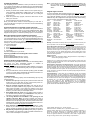
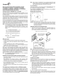
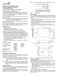
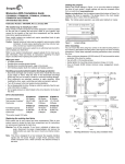
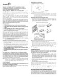
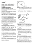
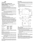
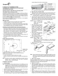
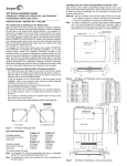
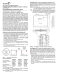
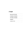
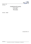
Setting the jumpers
Momentus 5400.3 Blade Server Installation Guide
ST9160821AB, ST9120822AB, ST9100828AB, ST980815AB,
ST960815AB and ST9402116AB
ATA Interface Disc Drives
Refer to the jumper settings in Figure 1 or on your drive label to configure
the drive for your system. Jumper settings can also be accessed online
from our web site at www.seagate.com.
Master or single drive: Use the options jumper block shown in Figure 1 to
configure the drive for operation. This jumper block is the 4-pin header
adjacent to pins 1 and 2 of the I/O signal pins.
Note. For blade server operation, use cable select (default) or master.
Publication Number: 100409997, Rev. A, April 2006
Drive is master (or single drive)
The easiest way to install your drive
Most blade servers are designed to make it possible to easily replace the
hard drive. Refer to your system’s user manual for the location of the hard
drive compartment and the specific instructions regarding replacement.
Caution. Special training or tools may be needed to service some blade
servers.
Refer to your system manufacturer’s support website for the most up-todate information. Read and follow all instructions regarding the proper
steps to be taken when replacing the hard drive.
Cable select
Figure 1.
Jumper settings
Drive mounting
What you need
•
•
•
•
Drive is slave
A Phillips screwdriver
Existing drive mounting screws
Existing blade server drive mounting framework, cage, or tray
ATA interface adapter (built into blade servers)
Handling precautions/electrostatic discharge protection
• Disc drives are fragile. Do not drop or jar the drive. Handle the drive only
by the edges or frame. Keep the drive in the electrostatic discharge
(ESD) bag until you are ready to install it to minimize handling damage.
• Drive electronics are extremely sensitive to static electricity. While
installing the drive, wear a wrist strap and cable connected to ground.
• Turn off the power to the blade server during installation. In most blade
server host systems, you do not need to shut down the entire system
chassis itself, just power to the blade server itself. Refer to the system’s
documentation for information specific to your particular system.
• Do not disassemble the drive. Doing so voids the warranty. See the warranty information on page 2.
• Do not apply pressure or attach labels to the circuit board or to the top of
the drive.
You can mount the drive using four screws in the side-mounting holes or
four screws in the bottom-mounting holes. See Figure 2 for drive mounting
dimensions. Follow these important mounting precautions when mounting
the drive:
• Allow a minimum clearance of 0.030 inches (0.76 mm) around the entire
perimeter of the drive for cooling.
• Use only M3 UNC mounting screws. (Reusing the existing screws may
be acceptable provided the maximum screw penetration depth of 0.098
inches is not exceeded.)
• Gently tighten the mounting screws (maximum torque: 4.0 in-lb).
• Four (4) threads (0.080 inches) minimum screw engagement recommended.
3.945 +/-0.0098
(100.2 +/-.25) 0.490 +/- .010
(12.446 +/- .254)
.157
(3.9878)
.399
(10.135)
0.680 +/- .010
(17.27 +/- .254)
Breather Hole
Do not cover
or seal.
2.750 +/- .0098
(69.85 +/- .25)
Drive characteristics
Formatted capacity**
Total number of sectors*
Cache size
ST9160821AB
160 Gbytes
312,581,808
8 Mbytes
ST9120822AB
120 Gbytes
234,441,648
8 Mbytes
Formatted capacity**
Total number of sectors*
Cache size
ST9100828AB
100 Gbytes
195,371,568
8 Mbytes
ST980815AB
80 Gbytes
156,301,488
8 Mbytes
Formatted capacity**
Total number of sectors*
Cache size
ST960815AB
60 Gbytes
117,210,240
8 Mbytes
ST9402116AB
40 Gbytes
78,140,160
8 Mbytes
inches
(mm)
3.567
(90.602)
.551
(13.99)
2X M3 X 0.5-6H
Mounting holes
Both sides
.12 min. full thread
.374 +/- .0078
(9.5 +/- .2)
2X .118
Both sides
3.567
(90.60)
.551
(13.99)
*One sector equals 512 bytes.
**One Gbytes equals one billion bytes when referring to hard drive capacity. Accessible capacity may vary depending on operating environment and
formatting.
Replacing the existing hard drive
Each system has its own unique hard drive compartment. Refer to your
system manual to locate the hard drive compartment and for instructions
on removing and replacing the hard drive.
Warning. Ensure that power to the drive is removed or turned off. In a
blade server, this typically means turning off power to the blade
server itself, not the host chassis.
Note. This drive is designed for a blade server that supplies interface signals and +5V power through a single 44-pin connector. Most blade
servers have a fixed connector that attaches directly to the drive.
Some blade servers allow two drives to be installed and setup in a mirrored
RAID configuration. If this is your situation, ensure that the storage capacities and speeds of the two drives are identical to avoid potential performance and reliability problems.
Recommended case
temp. measurement location
4X M3 X 0.5-6H
Mounting holes
.10 min. full thread
2.430
(61.722)
.160
(4.06)
Figure 2.
Mounting dimensions—end, top, side, and bottom views
Configuring the BIOS
After completing the drive installation, restart your blade server according
to your system documentation. Your blade server may automatically detect
your new drive. If your server does not automatically detect your new drive,
follow the steps below.
1. Restart your blade server. While it restarts, run the system setup program (sometimes called BIOS or CMOS setup). This is usually done
by pressing a special key, such as DELETE, ESC, or F1 during the
startup process.
2. Within the system setup program, instruct the blade server to auto
detect your new drive.
3. Save the settings and exit the setup program.
When your blade server restarts, it should recognize your new drive. If
your server still doesn’t recognize your new drive, see the troubleshooting
section on this sheet.
System manufacturer’s operating system restore CD
Refer to your blade server’s system documentation for specific instructions
on restoring the operating system on your newly installed hard drive. Many
computers require the use of an operating system restore CD, originally
shipped with the system, to reload the operating system on the hard drive.
Microsoft operating system installation instructions
For detailed information about installing a Microsoft operating system on
your new Seagate drive, refer to the Microsoft Knowledgebase article references below. To locate an article, go to http://support.microsoft.com and
enter the article number in any search box on the Microsoft web site. For
example, to view the Knowledgebase article for installing Windows XP on
your new Seagate drive:
1. Open your browser.
2. Go to http://support.microsoft.com.
3. Enter 313348 in the Microsoft web site search box.
4. Press Enter.
The article is displayed on your screen.
Operating systemMicrosoft Knowledgebase article numbers
Windows XP313348
Windows 2000/NT308209 (see also: 175761)
Windows Me/98/95255867 (see also: 166172)
Preparing the drive using DiscWizard
We recommend using DiscWizard Starter Edition to automatically partition
and format your drive. DiscWizard software is available at
www.seagate.com and is free. To run DiscWizard:
1. Insert your bootable DiscWizard Starter Edition diskette or CD and follow the instructions. DiscWizard will guide you through the installation
process.
2. Boot your blade server from the Windows operating system CD-ROM
or from your system startup diskette with the Windows CD loaded. Follow the instructions provided on your screen.
Troubleshooting
If your drive is not working properly, these troubleshooting tips may help
solve the problem.
1. Does the drive spin up? A spinning drive produces a faint whine and
clicking noise. If your drive does not spin, check that the power connector and interface cable are securely attached.
2. Does the computer recognize the drive? Verify that the drive is
enabled in the system CMOS or setup program. If not, select the auto
detect option and enable it. If your drive has a problem, it may not be
recognized by the system. If the operating system does not recognize
the drive, you need to load your host adapter drivers.
3. Does FDISK detect the drive? Run the FDISK program located on
your Windows startup diskette. Type fdisk/status to verify that your
hard drive is present and recognized by the system.
4. I’m running Windows 98 and FDISK is not reporting the full
capacity of my drive. Why? You need to upgrade your version of
FDISK if you are using the diskettes or CD that came with your original
Windows 95 or 98 operating system. Microsoft provides a free downloadable FDISK upgrade. See Microsoft Knowledgebase article number: 263044 located at http://support.microsoft.com.
5. Does ScanDisk find the drive defect-free? ScanDisk is a utility
located on your Windows startup diskette that scans the drive for
defects. If defects are detected, this may be an indication of a problem.
6. Why does my computer hang on startup? Verify that your system is
ATA compatible. You need either an ATA-compatible motherboard connector or ATA host adapter to use this drive.
Note. If these tips do not answer your question or solve the problem, contact your dealer or visit http://seatools.seagate.com to download
SeaTools™ disc diagnostics software and more troubleshooting
advice.
Seagate support services
For online information about Seagate products, visit www.seagate.com or
e-mail your disc questions to [email protected].
If you need help installing your drive, consult your dealer first. If you need
additional help, call a Seagate technical support specialist. Before calling,
note your system configuration and drive model number.
Africa
Australia
Austria
Belgium
China*
Denmark
France
Germany
Hong Kong
Hong Kong*
India
Indonesia
Ireland
Italy
Malaysia
Middle East
+31-20-316-7222
1800-14-7201
0 800-20 12 90
0 800-74 876
800-810-9668
80 88 12 66
0 800-90 90 52
0 800-182 6831
800-90-0474
001-800-0830-1730
1-600-33-1104
001-803-1-003-2165
1 800-55 21 22
800-790695
1-800-80-2335
+31-20-316-7222
Netherlands
New Zealand
Norway
Poland
Spain
Sweden
Switzerland
Singapore
Taiwan*
Thailand
Turkey
United Kingdom
USA/Canada/
Latin America
Other European
countries
0 800-732-4283
0800-443988
800-113 91
00 800-311 12 38
900-98 31 24
0 207 90 073
0 800-83 84 11
800-1101-150
00-800-0830-1730
001-800-11-0032165
00 800-31 92 91 40
0 800-783 5177
1-800 SEAGATE or
+1-405-324-4770
+31-20-316-7222
*Chinese
Warranty. To determine the warranty status of your Seagate disc drive, contact your
place of purchase or visit our web site at www.seagate.com for more information.
Return Merchandise Authorization (RMA). Run SeaTools to diagnose your drive
before requesting a return authorization. In addition, please verify that your drive is
defective by following the troubleshooting checklist in this guide. Seagate offers comprehensive customer support for all Seagate drives worldwide. Seagate customer
service centers are the only facilities authorized to service Seagate drives. Drive
return procedures vary depending on geographical location and are subject to current
international trade regulations.
Shipping the drive
Caution. Back up the data before shipping. Seagate assumes no responsibility for
data lost during shipping or service.
Shipping drive in an unapproved container voids the warranty. Pack the drive with
original box and packing materials. Use no other materials. This prevents electrical
and physical damage in transit.
Electromagnetic compliance for the European Union. This model complies with
the European Union requirements of the Electromagnetic Compatibility Directive 89/
336/EEC of 03 May 1989 as amended by Directive 92/31/EEC of 28 April 1992 and
Directive 93/68/EEC of 22 July 1993. Compliance of this drive, as a system component, was confirmed with a test system. We cannot guarantee that your system will
comply. The drive is not meant for external use (without properly designed enclosure,
shielded I/O cable, etc.).
Sicherheitsanleitung 1. Das Gerrät ist ein Einbaugerät, das für eine maximale
Umgebungstempeatur von 60°C vorgesehen ist. 2. Zur Befestigung des Lufwerks
werden 4 Schrauben 6-32 UNC-2A benötigt. Bei seitlicher Befestigung darf die maximale Länge der Schrauben im Chassis nicht merh als 3,3 mm und bei Befestigung an
der Unterseite nicht mehr als 5,08 mm betragen. 3. Als Versorgungsspannugen werden benötigt: +5V +/- 5% 1,00A. 4. Die Versorgungsspannung muss SELV entsprechen. 5. Alle Arbeiten auf dem Festplattte dürfen nur von Ausgebiletem
Serciepersonal durchgeführt werden. Bitte entfernen Sie nicht die Aufschriftenschilder des Laufwerkes. 6. Der Einbau des Laufwerkes muss den Anforderungen
gemäss DIN IEC 950 VDE 0805/05.90 entspreche.
© 2006 Seagate Technology LLC. All rights reserved.
Publication number: 100409997, Rev. A, April 2006, Printed in U.S.A.
Seagate, Seagate Technology, and the Seagate logo are registered trademarks or
trademarks of Seagate Technology LLC. DiscWizard, Momentus 5400.3 Blade
Server, and SeaTools are trademarks of Seagate Technology LLC. Other product
names are registered trademarks or trademarks of their owners. Seagate reserves
the right to change, without notice, product offerings or specifications.