1
L8
S2048 Yard Tractor
and
S2554 Garden Tractor
Serial No. (010,001- )
OPERATOR’S MANUAL
OMM138757 L8
North American Version
Litho in U.S.A.
English
INTRODUCTION
THANK YOU for purchasing a Scotts
product.
Read this manual and your attachment manual
thoroughly. Failure to do so could result in personal
injury or equipment damage.
c
WARNING: The Engine Exhaust from this
product contains chemicals known to the
State of California to cause cancer, birth
defects or other reproductive harm.
CALIFORNIA Proposition 65 Warning
This manual should be considered a permanent part of
your machine and should remain with the machine when
you sell it.
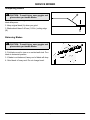
Measurements in this manual are metric units and their
U.S. customary equivalents. RIGHT-HAND and LEFTHAND sides are determined by facing in the direction
the machine will travel when going forward. When you
see a broken line arrow (------>), it indicates the part it is
pointing to is hidden.
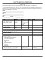
Record identification numbers below. Be sure to record
all the numbers to help in tracing the machine if it is
stolen. You also need to give these numbers to your
dealer when you order parts.
DATE OF PURCHASE: _______________________________
DEALER NAME: ____________________________________
DEALER PHONE: ___________________________________
TRACTOR SERIAL NUMBER (A), (Located on rear
of tractor): __ __ __ __ __ __ __ __ __ __ __ __ __
ENGINE SERIAL NUMBER (B), (Located on engine):
B
__ __ __ __ __ __ __ __ __ __ __ __ __
A
Introduction
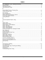
TABLE OF CONTENTS
Assembly ............................................................................................................................................... 1
Safety Signs........................................................................................................................................... 5
Controls ................................................................................................................................................. 8
Operating Machine ................................................................................................................................ 9
Operating Mower ................................................................................................................................. 26
Replacement Parts ............................................................................................................................. 32
Service Machine Safely ....................................................................................................................... 33
Service Interval Chart .......................................................................................................................... 35
Service Engine .................................................................................................................................... 37
Service Transmission........................................................................................................................... 44
Service Mower ..................................................................................................................................... 45
Service Electrical ................................................................................................................................. 49
Service Miscellaneous......................................................................................................................... 54
Removing Mower ................................................................................................................................. 62
Installing Mower................................................................................................................................... 64
Troubleshooting .................................................................................................................................. 65
Storing Machine................................................................................................................................... 70
Specifications....................................................................................................................................... 73
Warranty .............................................................................................................................................. 76
Index .................................................................................................................................................... 82
Service Literature ............................................................................................................................... 87
All information, illustrations and
specifications in this manual are based
on the latest information at the time of
publication. The right is reserved to
make changes at any time without
notice.
COPYRIGHT© 1998
Deere & Co.
OMM138757 L8
Table of Contents
NOTES
Notes
NOTES
Notes
NOTES
Notes
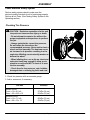
ASSEMBLY
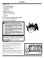
Identify Parts
Clear Plastic Bag Contains:
• Scotts Operator’s Manual
• Engine Owner’s Manual
• Safety Video
• Warranty Cards
Bag of Parts Contains:
• Hardware for Steering Wheel
• Hardware for Battery Cables
• Key Chain
• Padded Key
NOTE: There is an extra ignition key strapped to
one of the seat suspension springs.
Check and Connect Battery
c CAUTION: Prevent Battery Explosions:
- Keep sparks, lighted matches, and open
flame away from the top of battery. Battery
gas can explode.
- Never check battery charge by placing a
metal object across the posts. Use a voltmeter or hydrometer.
- Do not charge a frozen battery; it may
explode. Warm battery to 16 degrees C (60
degrees F).
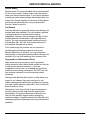
IMPORTANT: This battery comes fully charged. If
the mower is not used by the Service Expiration
Date indicated on the battery, charge the battery.
(See Charging the Battery in the Service Electrical section.)
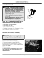
Check Battery
Battery is filled with acid and charged when it left the
factory. If necessary, charge the battery prior to
operation. (See Charging the Battery in ServiceElectrical Section.)
A
Locate label attached to battery. Find the service
expiration date information (A).
If battery is put into service after date shown, charge the
battery for a minimum of 1 hour at 6 - 10 amps.
Check battery voltage. Battery is fully charged at 12.6
volts.
Assembly - Page 1
M86467
ASSEMBLY
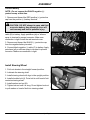
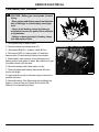
Connect Battery
NOTE: Do not remove the BLACK negative (–)
protective cap at this time.
1. Remove and discard the RED positive (+) protective
cap from the positive (+) battery terminal.
c CAUTION: DO NOT attempt to open, add fluid
or service battery. Any attempt to do so will
void warranty and lead to possible injury.
2. Connect blue harness wire (A) and RED positive (+)
cable (B) to battery. Apply petroleum jelly or silicone
spray to terminal to prevent corrosion. Make sure
connection is tight. Install the red terminal cover.
3. Remove and discard the BLACK (–) protective cap
from the negative battery terminal.
B
A
4. Connect black negative (–) cable (C) to battery. Apply
petroleum jelly or silicone spray to terminal to prevent
corrosion. Make sure connection is tight.
C
M97159
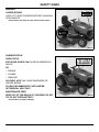
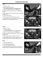
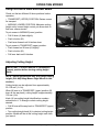
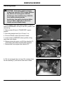
Install Steering Wheel
1. Put front wheels in the straight forward position.
2. Lubricate the steering shaft.
3. Install steering wheel with logo in the upright position.
B
4. Install shoulder bolt (A). Drive bolt in until head of bolt
contacts steering wheel.
A
5. Install washer and nut (B).
6. Tighten lock nut until it is snug. Do not tighten lock nut
to pull washer or head of bolt into steering wheel.
Assembly - Page 2
M88566
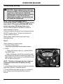
ASSEMBLY
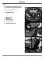
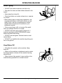
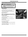
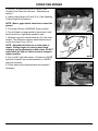
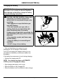
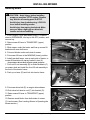
Check Engine Oil
IMPORTANT: To avoid engine damage, DO NOT
run engine if oil level is below ADD mark.
1. Lift hood.
A
Picture Note: Model S2048 used for photo purposes.
2. Remove dipstick (A). Wipe with clean cloth.
3. Insert the dipstick into the tube and rest the oil fill cap
on the tube. Do not thread the cap onto the tube.
4. Remove dipstick to check oil level.
5. Oil must be between ADD and FULL marks.
M97157
6. Add oil to FULL mark if necessary. DO NOT overfill.
(See See Engine Oil in Service Engine section.)
7. Install and tighten dipstick. Lower hood.
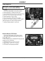
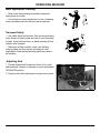
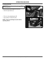
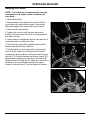
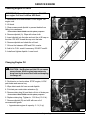
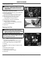
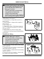
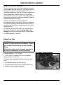
Break-In Electric PTO Clutch
Picture Note: Model S2554 used for photo purposes.
1. Start engine and push throttle lever (A) up to full
throttle (r) position.
2. With no load on mower, ENGAGE PTO (B) and allow
mower to run for 10 seconds.
3. DISENGAGE PTO and wait 10 seconds.
A
4. Repeat Steps 2 and 3 for 12-15 cycles.
5. PTO clutch is now properly burnished.
B
M97167
Assembly - Page 3
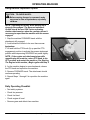
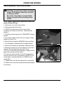
ASSEMBLY
Check Machine Safety System
Perform safety system check to make sure the
electronic safety interlock circuit is functioning properly.
Perform all six Tests. (See Testing Safety System in the
Operating section.)
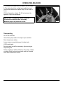
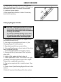
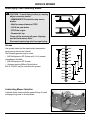
Checking Tire Pressure
c CAUTION: Explosive separation of a tire and
rim parts can cause serious injury or death:
- Do not attempt to mount a tire without the
proper equipment and experience to perform
the job.
- Always maintain the correct tire pressure.
Do not inflate the tires above the
recommended pressure. Never weld or heat a
wheel and tire assembly. The heat can cause
an increase in air pressure resulting in a tire
explosion. Welding can structurally weaken or
deform the wheel.
- When inflating tires, use a clip-on chuck and
extension hose long enough to allow you to
stand to one side and NOT in front of or over
the tire assembly.
- Check tires for low pressure, cuts, bubbles,
damaged rims or missing lug bolts and nuts.
1. Check tires for damage.
2. Check tire pressure with an accurate gauge.
3. Add or remove air, if necessary:
Tire Size
Pressure
Model S2048:
Front = 16 x 6.5 x 8
Rear = 23 x 9.50 x 12
97 kPa (14 psi)
83 kPa (12 psi)
Models S2554:
Front = 16 x 7.5 x 8
Rear = 24 x 12 x 12
83 kPa (12 psi)
69 kPa (10 psi)
Assembly - Page 4
SAFETY SIGNS
Safety-Alert Symbol
Read and recognize safety information. Be alert to the
potential for personal injury when you see this safetyalert symbol.
On your machine safety labels, the words DANGER,
WARNING, and CAUTION are used with this safetyalert symbol. DANGER identifies the most serious
hazards.
In this manual, the word CAUTION and this symbol call
attention to safety messages.
Machine Safety Labels
DANGER
ROTATING BLADES CUT OFF ARMS AND LEGS
• Do not mow when children or others are around
• Do not mow in reverse
• Look down and behind before and while backing
• Never carry children
WARNING
AVOID SERIOUS INJURY OR DEATH
• Drive up and down slopes, not across
• Avoid sudden turns
• If machine stops going uphill, stop blade and back
down slowly
• Keep safety devices (guards, shields, and switches)
in place and working
• Read operator’s manual
• When leaving machine:
–Stop engine
–Set park brake
–Remove key
Safety Signs - Page 5
M97152
SAFETY SIGNS
WARNING
LOADED SPRING
LOCK LIFT LEVER FORWARD BEFORE CHANGING
ATTACHMENTS
Picture Note: One decal on each side of tractor frame.
M97152
DANGER/POISON
SHIELD EYES.
EXPLOSIVE GASES CAN CAUSE BLINDNESS OR
INJURY.
NO
• SPARKS
• FLAMES
• SMOKING
SULFURIC ACID CAN CAUSE BLINDNESS OR
SEVERE BURNS
FLUSH EYES IMMEDIATELY WITH WATER.
GET MEDICAL HELP FAST.
MAINTENANCE-FREE
KEEP OUT OF THE REACH OF CHILDREN. DO NOT
TIP. DO NOT OPEN BATTERY!
Picture Note: Located on Battery
Safety Signs - Page 6
M97152
SAFETY SIGNS
DANGER
ROTATING BLADE
DO NOT PUT HANDS OR FEET UNDER OR INTO
MOWER WHEN ENGINE IS RUNNING
THROWN OBJECTS
BEFORE MOWING, CLEAR AREA OF OBJECTS THAT
MAY BE THROWN BY BLADE
DO NOT OPERATE MOWER WITHOUT DISCHARGE
CHUTE OR ENTIRE GRASS CATCHER IN PLACE
M97152
DANGER
ROTATING BLADE
DO NOT PUT HANDS OR FEET UNDER OR INTO
MOWER WHEN ENGINE IS RUNNING
Picture Note: Located on Left-Hand side of deck.
M97152
Certification Label
This OPEI label on your mower indicates that this model
has been certified by an independent laboratory for
compliance with American National Standard B-71.11996, “Safety Specifications” for Power Lawn Mowers,
Lawn and Garden Tractors, and Lawn Tractors.
1-1996
Safety Signs - Page 7
CONTROLS
Controls
Picture Note: Model S2554 used for photo purposes.
A - Engine Oil Pressure Light (Model S2554 Only)
B
A
B - Hour Meter (Model S2554 Only)
C - Battery Discharge Light
C
D - Light Switch
E
E - PTO Switch/RIO Switch
D
F - Choke Knob
G - Throttle Lever
H - Key Switch
I - Park Brake Lever
G
J - Brake Pedal
F
K - Forward Travel Pedal
L - Reverse Travel Pedal
M - Mower Deck Lift Lever
M97167
N - Cut Height Adjustment Lever
J
H
I
K
L
M97165
M
N
M97160
Controls - Page 8
OPERATING MACHINE
Operate Safely
• In addition to reading your Operator’s Manual, view
your Mowing Safety Video.
• Check brake action before you operate. Adjust or
service brakes as necessary.
• Inspect machine before you operate. Be sure
hardware is tight. Repair or replace damaged, badly
worn, or missing parts. Be sure guards and shields are
in good condition and fastened in place. Make any
necessary adjustments before you operate.
• Clear work area of objects that might be thrown. Keep
people and pets out of the work area. Stop machine if
anyone enters the area.
• If you hit an object, stop the machine and inspect it.
Make repairs before you operate. Keep machine and
attachments properly maintained and in good working
order.
• DO NOT leave machine unattended when it is
running.
• Only operate during daylight or with good artificial
light.
• Be careful of traffic when operating near or crossing
roadways.
• Do not wear radio or music headphones while
operating the machine. Safe operation requires your full
attention.
Park Safely
• Stop machine on a level surface, not on a slope.
• Disengage mower blades.
• Lower attachments to the ground.
• Engage park brake.
• STOP engine.
• Remove key.
• Before you leave the operator’s seat, wait for engine
and all moving parts to STOP.
Operating Machine - Page 9
OPERATING MACHINE
Rotating Blades are Dangerous - Protect
Children and Prevent Accidents
PROTECT CHILDREN:
• Never assume that children will remain where you last
saw them. Children are attracted to mowing activity, stay
alert to the presence of children.
• Keep children in the house when you are operating
the machine.
• Turn machine off if a child enters the mowing area.
• Use extra care when you come to blind corners,
shrubs, trees, or other objects that may block your
vision.
• DO NOT let children or an untrained person operate
the machine.
• DO NOT carry or let children ride on machine or any
attachment. DO NOT tow children in a cart or trailer.
HELP PREVENT SERIOUS OR FATAL ACCIDENTS:
• Be alert at all times, drive forward carefully. People
especially children can move quickly into the mowing
area before you know it.
• Back carefully. Disengage mower blades and look
behind the machine carefully, especially for children,
before you back up.
• DO NOT mow in reverse unless it is absolutely
necessary.
• Disengage mower blades when you are not mowing.
• DO NOT operate machine if you are under the
influence of drugs or alcohol.
Operating Machine - Page 10
OPERATING MACHINE
Avoid Tipping
• DO NOT drive where machine could slip or tip.
• Stay alert for holes and other hidden hazards in the
terrain.
• Keep away from drop-offs.
• Slow down before you make a sharp turn or operate
on a slope.
• When pulling loads or using heavy equipment, use
only approved hitches, limit loads to those you can
safely control, and use counterweights or wheel
weights when required per this manual or your
attachment manual.
• Drive up and down a hill—not across. Be careful
when you change direction on a slope.
• DO NOT stop when going up hill or down hill. If
machine stops going up hill, DISENGAGE mower
blades and back down slowly.
• DO NOT mow wet grass. Reduced traction could
cause sliding.
• DO NOT try to stabilize the machine by putting your
foot on the ground.
Keep Riders Off
• Only allow the operator on the machine. Keep
riders off.
• Riders on the machine or attachment may be struck
by foreign objects or thrown off the machine causing
serious injury.
• Riders obstruct the operator’s view resulting in the
machine being operated in an unsafe manner.
Operating Machine - Page 11
OPERATING MACHINE
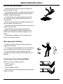
Wear Appropriate Clothing
• Wear close fitting clothing and safety equipment
appropriate for the job.
• Loud noise can cause impairment or loss of hearing,
wear a suitable protective device such as earplugs.
Transport Safely
• Use safety lights and devices. Slow moving machines
when driven on public roads are hard to see, especially
at night. Avoid personal injury or death resulting from a
collision with a vehicle.
• Whenever driving on public roads, use flashing
warning lights and turn signals according to local
regulations. Extra flashing warning lights may need to
be installed.
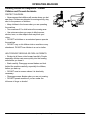
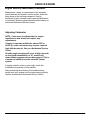
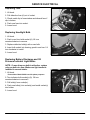
Adjusting Seat
1. Tip seat forward and loosen two knobs (A) to slide
seat assembly forward or rearward to most comfortable
OPERATOR position.
2. Tighten knobs after adjustment to keep seat in place.
A
M97164
Operating Machine - Page 12
OPERATING MACHINE
Using the Park Brake
c CAUTION: The machine may begin to move
when engine is shut off and park brake is not
engaged. To avoid injury, always LOCK park
brake before getting off tractor or leaving
tractor unattended.
LOCKING PARK BRAKE:
1. Push brake pedal (A) all the way down.
A
B
2. Lift park brake lever (B) up.
3. Release pedal and park brake lever. Pedal should
stay down and park brake lever should stay LOCKED in
UP position.
UNLOCKING PARK BRAKE:
1. Push and hold brake pedal (A) down.
2. Push park brake lever (B) down to UNLOCK park
brake.
M97165
3. Release pedal.
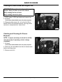
Using Headlights
Picture Note: Model S2554 used for photo purposes.
Push top of light switch (A) to turn headlights ON.
Push bottom of light switch to turn headlights OFF.
A
M97167
Operating Machine - Page 13
OPERATING MACHINE
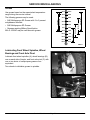
Checking Indicator Lights and Hour Meter
Picture Note: Model S2554 used for photo purposes.
• (b) BATTERY DISCHARGE light (A) should go out
when throttle lever is moved to the HIGH IDLE/Mowing
(a) position. The voltage light may remain on for
several minutes while the battery is being charged.
B
C
A
• (o) OIL PRESSURE light (B), on Model S2554 only,
will come on when engine starts and should go out
within 5 seconds.
If indicator lights stay on longer than given time, STOP
engine.
• HOUR METER (C), on Model S2554 only, shows the
number of hours the engine has run. To display hours,
key must be in the “ON” position. Check the hour meter
daily to see what services need to be done.
M97167
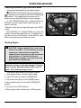
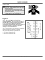
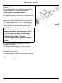
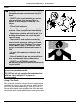
Starting Engine
c CAUTION: Engine exhaust fumes can cause
sickness or death. • If it is necessary to run an
engine in an enclosed area, remove the
exhaust fumes from the area with an exhaust
pipe extension. • If you do not have an
exhaust pipe extension, open the doors and
get outside air into the area.
IMPORTANT: Do not operate starter more than 20
seconds at a time, or you may damage it. If engine
does not start: Wait two minutes before you try
again. See Troubleshooting section.
Picture Note: Model S2554 used for photo purposes.
1. Lock the park brake or depress brake pedal.
2. Push PTO switch (A) down to DISENGAGE.
3. Pull choke knob (B) out to the ON (k) position.
4. Move throttle lever (C) to the HALF-SPEED (R)
position.
A
C
B
5. Turn key (D) to START position.
6. When engine starts, release key to RUN position.
D
M97167
Operating Machine - Page 14
OPERATING MACHINE
7. Check starting conditions:
• If engine is COLD: Gradually return the choke to
the OFF position after the engine starts and warms
up.
• If engine is WARM: Return choke to the OFF
position as soon as the engine starts.
8. Let engine run for a couple of minutes to warm-up
before operating machine.
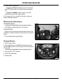
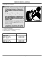
Warming and Idling Engine
WARMING ENGINE:
Picture Note: Model S2554 shown for photo purposes.
• Run Engine at half speed for 2–3 minutes.
A
IDLING ENGINE:
• Engine is air-cooled and needs a large volume of air
to keep cool. Keep air intake screen (A) on top of engine
clean.
• Avoid unnecessary engine idling.
M97151
Stopping Engine
1. STOP tractor travel.
2. Move throttle lever (A) MIDWAY between slow (t)
and fast (r) positions. Let the engine run a minimum of
15 seconds.
A
Picture Note: Model S2554 shown for photo purposes.
3. Turn key (B) to OFF position.
B
4. LOCK the park brake.
5. Remove key.
M97151
Operating Machine - Page 15
OPERATING MACHINE
Using and Stopping Automatic Transmission
c CAUTION: TO AVOID INJURY:
• Before moving forward or rearward, make
sure area is clear of bystanders, especially
children.
• Disengage mower before backing up.
UNLOCK park brake.
To Travel Forward:
• Slowly push down forward pedal (A). Tractor will travel
faster the farther down you push the pedal.
6.
C
• Release forward pedal, tractor will automatically
return to neutral and STOP.
To Travel in Reverse:
NOTE: The engine and any operating attachment
will stop as the REVERSE pedal is depressed with
attachment engaged.
1. Bring the vehicle to a stop.
A
B
2. Push PTO knob down to the OFF position to
disengage attachment.
3. Look behind the vehicle to be sure there are no
bystanders nearby.
4. Push down reverse pedal (B).
For Emergency Stopping:
• Release either travel pedal. Tractor will automatically
return to neutral and STOP.
• Push down on brake pedal (C). Tractor brakes will be
applied to assist in stopping.
Operating Machine - Page 16
M97165
OPERATING MACHINE
Pushing Machine
IMPORTANT: Avoid transmission damage, DO
NOT tow machine.
A
To move machine when engine is STOPPED:
• Unlock the park brake (A).
M97165
• Pull out on free-wheeling lever (B).
• Push machine to desired location.
NOTE: Push free-wheeling lever (B) in before
operating tractor.
B
M97163
Operating Machine - Page 17
OPERATING MACHINE
Using Reverse Implement Option
CAUTION: TO AVOID INJURY:
c Before moving forward or rearward, make
sure area is clear of bystanders, especially
children.
NOTE: Operating the mower while backing up is
strongly discouraged. The Reverse Implement
Option should be used ONLY when operating
another attachment or when the operator deems it
necessary to reposition the machine with the mower
engaged.
1. Stop the machine FORWARD travel with the
attachment still engaged.
A
2. Look behind the vehicle to be sure there are no
bystanders.
3. Lift and hold the PTO knob (A) up past the PTO
engagement position to activate the reverse implement
position while depressing REVERSE foot pedal slightly.
NOTE: If the engine and attachment stop while
repositioning the machine, return PTO knob to the
OFF position and restart the machine. (See Starting
The Engine in this section.) Begin again with Step 2.
4. As the machine begins to move backward, release
the PTO knob and reposition the machine.
5. Resume FORWARD travel. The attachment should
continue operating.
6. Repeat Steps 1 through 5 to reposition the machine
again.
Daily Operating Checklist
• Test safety systems.
• Check tire pressure.
• Check fuel level.
• Check engine oil level.
• Remove grass and debris from machine.
Operating Machine - Page 18
M96052
OPERATING MACHINE
Testing Safety Systems
c CAUTION: Engine exhaust fumes can cause
sickness or death. • If it is necessary to run an
engine in an enclosed area, remove the
exhaust fumes from the area with an exhaust
pipe extension. • If you do not have an
exhaust pipe extension, open the doors and
get outside air into the area.
NOTE: Your Tractor is equipped with a
ELECTRONIC SAFETY INTERLOCK. Engine will not
start unless: PTO switch is DISENGAGED; Brake
pedal is depressed OR parking brake is set.
Use the following checkout procedure to check for
normal operation of tractor.
If there is a malfunction during one of these procedures,
DO NOT operate tractor. (Contact your Authorized
Service Center for service.)
Perform these tests in a clear open area. Keep
bystanders away.
Test 1
Check operation of indicator lights:
1. Turn key to RUN position.
Picture Note: Model S2554 used for photo purposes.
2. LOOK:
• Engine Oil Pressure Light (A), on Model S2554
Only, MUST light.
• Battery Discharge Light (B) will momentarily light,
this indicates the system is functioning properly. If the
light remains on start engine and move throttle to high
idle, the light should go out.
A
B
C
NOTE: The battery discharge light may remain on
for several minutes while the battery is being
charged.
3. If one indicator does not light, see Replacing Indicator
Light Bulb in Service – Electrical section.
4. If new indicator bulb does not light or no indicators
work, contact your Authorized Service Center for
service.
Operating Machine - Page 19
M97167
OPERATING MACHINE
Test 2
Picture Note: Model S2554 used for photo purposes.
1. Operator on seat.
2. UNLOCK the park brake.
3. Push PTO switch (A) down to DISENGAGE.
A
4. Try to start engine.
5. Engine MUST NOT start. If engine starts, there is a
problem with your safety interlock circuit.
M97167
Test 3
Picture Note: Model S2554 used for photo purposes.
1. Operator on seat.
2. LOCK the park brake.
3. Pull PTO switch (A) up to ENGAGE.
A
4. Try to start engine.
5. Engine MUST NOT start. If engine starts, there is a
problem with your safety interlock circuit.
M97167
Test 4
Picture Note: Model S2554 used for photo purposes.
1. Operator on seat.
2. LOCK the park brake.
3. Push PTO switch (A) down to DISENGAGE.
4. Start engine and move throttle lever (B) to HALFSPEED (R) position.
B
A
5. Pull PTO switch (A) up to ENGAGE.
6. Move throttle lever (B) to FAST (r) speed position.
7. Raise up off of seat. DO NOT get off tractor.
8. Engine MUST stop. If engine does not stop, there is a
problem with your safety interlock circuit.
Operating Machine - Page 20
M97167
OPERATING MACHINE
Test 5
1. Operator on seat.
A
2. Push brake pedal (A) down.
Picture Note: Model S2554 used for photo purposes.
3. Push PTO switch (B) down to DISENGAGE.
4. Release forward travel pedal (C) to N (NEUTRAL)
position.
C
5. Start engine and move throttle lever (D) to FAST (r)
speed position.
M97165
6. Release brake slowly.
7. Raise up off of seat. DO NOT get off tractor.
8. Engine MUST stop. If engine does not stop, there is a
problem with your safety interlock circuit.
D
B
M97167
Test 6
1. Operator on seat.
2. Lock the park brake.
Picture Note: Model S2554 used for photo purposes.
3. Push PTO switch (A) down to DISENGAGE.
B
A
4. Start engine and move throttle lever (B) to FAST (r)
speed position.
5. Raise up off of seat. DO NOT get off tractor.
6. Engine MUST remain running. If engine does stop,
there is a problem with your safety interlock circuit.
M97167
Test 7
1. LOCK the park brake (A).
A
2. Pull out free-wheeling lever.
3. Try to push machine manually.
4. Park brake MUST prevent machine from moving. If
machine moves, parking brake needs to be adjusted.
M97165
Operating Machine - Page 21
OPERATING MACHINE
Test 8
c CAUTION: TO AVOID INJURY: Before moving
rearward, make sure area is clear of
bystanders, especially children.
Test Reverse Implement Option:
1. Start engine.
2. Engage PTO to start attachment.
3. Look behind the vehicle to be sure there are no
bystanders.
4. Begin REVERSE travel by depressing REVERSE foot
pedal.
5. Attachment and engine should stop operation. If
attachment or engine continues to operate while tractor
travels in REVERSE, do not continue to operate
attachment. See your Authorized service center for
service.
Avoid Damage to Plastic and Painted
Surfaces
• DO NOT wipe plastic parts unless rinsed first. (See
Correct Cleaning Care in Service-Miscellaneous
section.)
• Insect repellent spray may damage plastic and
painted surfaces. Do not spray insect repellent near
machine.
• Be careful not to spill fuel on machine. Fuel may
damage surface. Wipe up spilled fuel immediately.
Operating Machine - Page 22
OPERATING MACHINE
Avoid Using Ground Engaging Equipment
(Model S2048 Only)
IMPORTANT: Your S2048 tractor is NOT intended
for use with ground engaging equipment. Use of
such equipment could result in damage to
transmission components.
Tractor Model S2048 is not intended for use with ground
engaging equipment such as a rear tiller, disk, dirt blade
or plow.
Using Front Weights
c CAUTION: Tractor front wheel weights
improve stability in most slope operation. To
avoid injury, add front wheel weights for
better front-end stability and steering when
using a rear mounted attachment or pulling a
cart.
NOTE: Before installing wheel weights on your
machine, MAKE SURE that the tire valve stems are
facing the inside.
Install front wheel weights for better stability and
steering control when you use equipment such as the
rear-mounted grass bagger or dumpcart.
Remove front wheel weights when not required.
Using Rear Wheel Weights
IMPORTANT: When adding weight to rear of
tractor, use wheel weights only.
34 kg (75 lbs.) MAX. each wheel.
Use of rear wheel weights is recommended when an
attachment, such as snowthrower or snow blade is
used.
Operating Machine - Page 23
OPERATING MACHINE
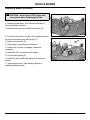
Installing the Chains
NOTE: Tire chains are recommended for use with
snowthrower and, under certain conditions, the
front blade.
1. Park vehicle safely.
2. Remove chains from bag and lay out flat with the
cross chain hook ends facing upward. Remove any
twists and tangles from cross chain and rim chain.
3. Drive machine onto chains.
4. Drape chain over tire with the lever fastener on
outside of tire and cross link hooks (A) facing upward
and away from tire.
5. Adjust chain for straightness and an even amount of
cross chain links on each side of tire.
A
M73743
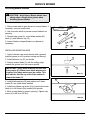
6. Place the first cross chain (opposite the end with
fastener and inside hook) under tire.
7. Pull the inside rim chain tight and hook the inside
hook. Pull the outside rim chain tight and hook the
outside lever fastener (B) by running the end through a
free link (C). Close the fastener by rotating it back 180
degrees and engaging the hook (D) on the end of the
fastener into a rim chain link (E). Make sure the chain is
centered on the tire with approximately the same
number of free rim links (F) on the inside and outside.
C
B
D
M73744
E
F
M73745
Operating Machine - Page 24
OPERATING MACHINE
8. Tie excess rim chain links (G) back to the rim chain.
9. The chain should be as tight as possible by hand.
Unhook the fastener and repeat Step 5 if the chain is
loose.
G
10.Drive forward on chains 30’-40’ and recheck for
tightness. Adjust as necessary.
IMPORTANT: Periodically check chains for
looseness and adjust when necessary.
Maintain proper air pressure in tires.
Transporting
Do not tow machine.
Use a heavy-duty trailer to transport your machine.
Drive forward onto trailer.
Lower mower or any attachment to trailer deck.
LOCK park brake.
Be sure trailer has all the necessary lights and signs
required by law.
Fasten machine to trailer with heavy-duty straps, chains,
or cables. Both front and rear straps must be directed
down and outward from tractor.
Operating Machine - Page 25
M73746
OPERATING MOWER
Operating Mower Safely
• In addition to reading your Operator’s Manual, view
your Mowing Safety Video.
Check Ground Conditions
• Clear mowing area of objects that might be thrown.
Keep people and pets out of mowing area.
• Study mowing area. Set up safe mowing pattern. Do
not mow under conditions where traction or stability is
doubtful.
• First, test drive area with PTO switch DISENGAGED
and mower lowered. Slow down when you travel over
rough ground.
Avoid Injury From Contacting Blades
Before you dismount to unplug or adjust mower:
• DISENGAGE PTO switch to stop mower blades.
• STOP the engine.
• LOCK the park brake.
• Remove key.
• Wait for mower blades to STOP.
• Keep hands, feet and clothing away from mower deck
when engine is running.
• DISENGAGE PTO switch to stop mower blades when
you are not using mower.
Operating Mower - Page 26
OPERATING MOWER
Using Lift Lever to Raise and Lower Mower
Check out the two different lift lever positions before
operation:
B
• TRANSPORT (UPPER) POSITION: Raises mower
for transport.
• MOWING (LOWER) POSITION: Maintains cutting
height set by mower height control yet allows deck to
float over uneven terrain.
A
To put mower in MOWING (lower) position:
• Pull lift lever (A) back slightly.
• Push in button (B).
• Push lever forward until it latches down.
M97160
To put mower in TRANSPORT (upper) position:
• Push forward on lift lever (A) slightly.
• Push in button (B).
• Pull lever back until it latches.
Adjusting Cutting Height
IMPORTANT: Lift lever must be in TRANSPORT
(upper) position before turning cutting height
knob.
NOTE: Adjust gage wheels after you change cutting
height. (See Adjusting Mower Gage Wheels in this
section.)
Cutting height can be adjusted from approximately
25–100 mm (1–4 in).
When lift lever is in TRANSPORT (upper) position (lift
lever all the way back), cutting height is approximately
100 mm (4 in).
Knob (A) has cutting height identification numbers
embossed in it. To change or attain cutting height
desired:
A
• Pull lift lever all the way back to TRANSPORT (upper)
position.
• Turn cutting height knob (A) to desired cutting height
position. Mower will be at this cutting height each time
you lower it.
Operating Mower - Page 27
M97170
OPERATING MOWER
Adjusting Mower Gage Wheels
c CAUTION: To avoid injury, before you adjust
gage wheels: STOP engine, remove key, and
wait for blades to STOP.
IMPORTANT: Mower gage wheels must not ride
on ground to support mower weight. Adjust gage
wheels each time you change cutting height.
1. Check tractor tire pressure. Inflate tires to the correct
pressure. (See Checking Tire Pressure in Service Miscellaneous section.)
D
2. Raise mower lift lever to TRANSPORT (upper)
position and adjust cutting height. (See Adjusting
Cutting Height in this section.)
C
A
3. Remove bolt (A), bushing (B), washer (C), and tighten
with nut (D).
NOTE: Bottom of gage wheels should be
approximately 6-13 mm (1/4-1/2 in) from the ground
when properly adjusted.
4. Move mower gage wheels, one on each side, to one
of four holes for desired position.
5. Install bolt and tighten with nut.
6. Move lift lever forward to MOWING (lower) position.
7. Check distance from gage wheel to ground.
8. Adjust gage wheels if necessary.
Adjusting Mower Level (Side-to-Side)
c CAUTION: To avoid injury, before you adjust
mower: STOP engine, remove key, and wait
for blades to STOP.
Be careful, sharp edges on mower blades.
Always wear gloves when handling mower
blades.
NOTE: A deck leveling gauge (Part Number
TY15272) to aid in deck leveling may be obtained
through your Authorized Service Center at a
nominal cost.
1. Park tractor on a hard, level surface.
2. Stop engine and remove key.
Operating Mower - Page 28
B
M88571
OPERATING MOWER
3. CHECK: Tire pressures must be correct. (See
Checking Tire Pressure in Service – Miscellaneous
section.)
4. Adjust cutting height to 50 mm (2 in). (See Adjusting
Cutting Height in this section.)
NOTE: Mower gage wheels should not contact the
ground.
5. Put mower lift lever in MOWING (lower) position.
M40434
6. Turn left blade by hand parallel to tractor axle. Hold
drive belt and turn right blade parallel to axle.
7. Measure from each outside blade tip (A) to the level
surface. The difference between measurements must
not be more than 3 mm (1/8 in).
NOTE: Adjustable lift links are on both sides of
mower. Cutting height can closely match knob
setting by using adjustment on both sides. DO NOT
adjust deck too high or it will not lock in transport
(upper) position.
A
M40161
8. Turn nut (B), (right side shown): Clockwise to RAISE
right side of mower and counterclockwise to LOWER
right side of mower.
9. Check side-to-side measurements and readjust if
necessary.
B
M88586
Operating Mower - Page 29
OPERATING MOWER
Adjusting Mower Level (Front-to-Rear)
c CAUTION: To avoid injury, before you adjust
mower: STOP engine, remove key, and wait
for blades to STOP.
Be careful, sharp edges on mower blades.
Always wear gloves when handling mower
blades.
NOTE: Mower gage wheels should not contact the
ground during leveling.
1. Park tractor on a hard, level surface.
2. Stop engine and remove key.
3. CHECK: Tire pressure must be correct. (See
Checking Tire Pressure in Service – Miscellaneous
section.)
4. Pull lift lever all the way back to TRANSPORT (upper)
position.
A
5. Turn mower depth control knob (A) to adjust cutting
height to 50 mm (2 in).
6. Move lift lever forward to MOWING (lower) position.
7. Turn left blade so blade tip points straight forward.
M97170
8. Hold drive belt and turn right blade straight forward.
9. Measure from the front of each blade tip to the level
surface. The front blade tips must be 6–9 mm
(1/4–3/8 in.) lower than rear blade tips or blades will cut
grass twice and tips will turn brown.
10.Loosen two rear nuts (B) on front lift rod assembly
and turn two front nuts (C) clockwise to RAISE front of
mower deck or counterclockwise to LOWER front of
mower deck.
11.Tighten rear nuts (B) after adjustment is completed.
12.Check front-to-rear deck measurements and readjust
if necessary.
Operating Mower - Page 30
B
C
B
M88578
OPERATING MOWER
Engaging Mower
IMPORTANT: Operate mower at HIGH IDLE/
Mowing (a) when mowing or after mower blades
are engaged.
Machine may require 2-3 minutes warm-up period
before engaging the mower deck.
1. START engine.
Picture Note: Model S2554 shown for photo purposes.
2. Move throttle lever (A) to the FAST (r) position.
A
B
3. Lower mower to cutting height.
4. Pull PTO switch (B) up to ENGAGE mower.
NOTE: Any operating attachment and the engine
will stop as the REVERSE foot pedal is depressed
with attachment engaged.
M97151
5. Disengage PTO before shifting to REVERSE.
Disengaging Mower
Push PTO switch (A) down to DISENGAGE mower.
Picture Note: Model S2554 shown for photo purposes.
A
If you hit an object with mower while mowing, STOP
mower and engine immediately. Inspect mower for
damage.
Dismounting to Inspect or Unplug Mower or
Optional Bagger
c CAUTION: To help prevent personal injury, do
the following steps before you dismount to
inspect or unplug mower or bagger.
1. STOP machine.
2. Push PTO switch down to DISENGAGE mower.
3. Move throttle lever to SLOW (t) position.
4. Lower mower to the ground.
5. LOCK park brake.
6. STOP engine.
7. Remove key.
8. Wait for all moving parts to STOP.
Operating Mower - Page 31
M97151
REPLACEMENT PARTS
WE RECOMMEND quality parts and lubricants, available at your Authorized Service Center.
PART NUMBERS MAY CHANGE, use part numbers listed below when you order. If a number
changes, your dealer will have the latest number.
WHEN YOU ORDER PARTS, your Authorized Service Center needs your machine serial number and
engine serial number. These are the numbers that you have recorded on the inside front cover of this
manual.
ALL PART NUMBERS shown are available through your Authorized Service Center.
Parts for Tractor and Mower Deck
ITEM
PART NUMBER
Air Cleaner Elements (Model S2048):
Foam Precleaner
M133094
(Kohler #24 083 01)
Paper Element
M133095
(Kohler #47 083 03)
Air Cleaner Elements (Model S2554):
Foam Precleaner
M133094
(Kohler #24 083 01)
Paper Element
M133095
(Kohler #47 083 03)
Fuel Filter
M132403
Oil Filter
AM125424
(Kohler #12 050 01)
Battery
TY21752
Spark Plug
Champion – RC12YC
(Kohler #12 132 02)
Fuse-15 amp
99M7065
Headlight Bulb
AD2062R
(GE #1156)
Belts (48-Inch Mower):
Primary (PTO clutch to upper deck sheave)
Secondary (Lower deck sheave to blade spindles
M131237
M110318
Belts (54-Inch Mower):
Primary (PTO clutch to upper deck sheave)
Secondary (Lower deck sheave to blade spindles
M131237
M118685
Blade (48-Inch Mower)
M115495
Blade (54-Inch Mower)
M115496
Leveling Gauge
TY15272
(Part numbers are subject to change without notice. Part Numbers may be different outside the U.S.A.)
If you would like a copy of the Parts Catalog for this machine, please use the Order Form in the
SERVICE LITERATURE section.
Replacement Parts - Page 32
SERVICE MACHINE SAFELY
Practice Safe Maintenance
• Understand service procedure before doing work.
Keep area clean and dry.
• Never lubricate, service, or adjust machine while it is
moving. Keep safety devices in place and in working
condition. Keep hardware tight.
• To prevent them from getting caught, keep hands,
feet, clothing, jewelry, and long hair away from any
moving parts.
• Before servicing machine, disengage all power and
stop the engine. Let engine cool.
• Securely support any machine elements that must be
raised for service work.
• Keep all parts in good condition and properly
installed. Fix damage immediately. Replace worn or
broken parts. Remove any buildup of grease, oil, or
debris.
• Unauthorized modifications to the machine may
impair its function and safety.
Wear Appropriate Clothing
• Wear close fitting clothing and safety equipment
appropriate for the job.
• Loud noise can cause impairment or loss of hearing,
wear a suitable protective device such as earplugs.
• Do not wear radio or music headphones while
servicing the machine. Safe service requires your full
attention.
Avoid Injury From Contacting Blades
Before you unplug or adjust machine:
• STOP the engine.
• Remove key.
• Wait for blades to STOP.
• Keep hands, feet and clothing away from blades when
engine is running.
Service Machine Safely - Page 33
SERVICE MACHINE SAFELY
Handling Waste Product and Chemicals
• Waste products such as used oil, fuel, coolant, brake
fluid, and batteries, can harm the environment and
people.
• DO NOT use beverage containers for waste fluids someone may drink from them.
• See your local Recycling Center or Authorized
Service Center to learn how to recycle or get rid of
waste products.
• A Material Safety Data Sheet (MSDS) provides
specific details on chemical products: physical and
health hazards, safety procedures, and emergency
response techniques. See your Authorized Service
Center for the MSDS on chemical products used with
your machine.
Service Machine Safely - Page 34
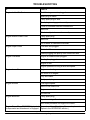
SERVICE INTERVAL CHART
Service Intervals
Please use the following timetables to perform routine maintenance on your machine. Service
procedures included in this manual but not on this chart are to be performed on an as needed basis.
IMPORTANT: To extend engine life, when operating mower in extreme heat, dust or other
severe conditions, service air cleaner and oil filter more often than shown.
Before Each Use
Check fuel level.
Check engine oil level.
Check air intake and cooling areas, clean as necessary.
Test safety systems.
Check tire pressure.
Check/tighten loose hardware.
After First 2 Hours
Adjust blade belt tension.
Change engine oil.
Every 8 Hours
Check brakes.
Check tire pressure.
Check engine oil level.
Every 25 Hours
Sharpen/replace blades.
Lubricate front axle and mower spindles.
Check battery and clean battery terminals.
Service air filter pre-cleaner.
Clean air intake screen.
Check transmission oil level.
Every 50 Hours
Inspect muffler.
Every 100 Hours
Change engine oil.
Check/tighten loose hardware.
Check drive belt tension.
Clean engine cooling fins
Replace engine oil filter.
Replace spark plugs.
Replace air filter paper cartridge.
Every Season
Check blade belt tension.
Service air filter pre-cleaner.
Clean air screen.
Replace spark plugs.
Replace fuel filter.
Service Interval Chart - Page 35
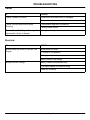
SERVICE INTERVAL CHART
Before Storage
Check/tighten loose hardware.
Lubricate front axle and mower spindles.
Clean battery terminals.
Change engine oil.
Inspect muffler.
Check transaxle cooling.
Service Record
DATE
SERVICE PERFORMED
Service Interval Chart - Page 36
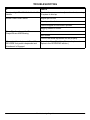
SERVICE ENGINE
Engine Warranty Maintenance Statement
Maintenance, repair, or replacement of the emission
control devices and systems on this engine, which are
being done at the customers expense, may be
performed by any nonroad engine repair establishment
or individual. Warranty repairs must be performed by an
authorized Authorized Service Center.
Adjusting Carburetor
NOTE: Carburetor is calibrated by the engine
manufacturer and should not require any
adjustments.
If engine is operated at altitudes above 1829 m
(6,000 ft), some carburetors may require a special
high altitude main jet. See your Authorized Service
Center.
Possible engine surging will occur at high rpm with
no load (with transmission in “N” neutral and
mower blade engagement lever disengaged). This is
a normal condition due to the emission control
system.
If engine is hard to start or runs rough, check the
Troubleshooting section of this manual.
After performing the checks in the troubleshooting
section and your engine is still not performing correctly,
contact an authorized Authorized Service Center.
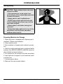
Service Engine - Page 37
SERVICE ENGINE
Avoid Fumes
c CAUTION: Engine exhaust fumes can cause
sickness or death:
- If it is necessary to run an engine in an
enclosed area, use an exhaust pipe extension
to remove the fumes.
- Always work in a well ventilated area.
Engine Oil
NOTE: Air cooled engines run hotter than
automobile engines. The use of multi-viscosity oil
such as (10W-30) in ambient temperatures above 4 °
C (40° F) will result in higher than normal oil
consumption. If multi-viscosity oil is used, check oil
level more frequently to prevent any possible
damage due to lack of lubrication.
Use oil viscosity based on the expected air temperature
range during the period between oil changes.
Use a high quality detergent oil classified as:
• API Service Classification SG
• API Service Classification SH
Service Engine - Page 38
SERVICE ENGINE
Checking Engine Oil Level
IMPORTANT: To avoid engine damage, DO NOT
run engine if oil level is below ADD mark.
1. Park tractor on a level surface. STOP engine. Let
engine cool.
A
2. Lift hood.
3. Clean area around dipstick to prevent debris from
falling into crankcase.
Picture Note: Model S2048 used for photo purposes.
4. Remove dipstick (A). Wipe with clean cloth.
M97157
5. Insert dipstick into the tube and rest the oil fill cap on
the tube. DO NOT thread the cap onto the tube.
6. Remove dipstick and check the oil level.
7. Oil must be between ADD and FULL marks.
8. Add oil to FULL mark if necessary. DO NOT overfill.
9. Install and tighten dipstick. Lower hood.
Changing Engine Oil
c CAUTION: Hot Engine and Hot Oil can cause
severe burns. Allow engine temperature to
drop from hot to warm level before attempting
to change oil.
1. Run engine to warm oil.
2. Park tractor on level surface. STOP engine, LOCK
park brake and remove key.
B
3. Wipe debris and dirt from around dipstick.
4. Put drain pan under drain extension (A).
5. Remove drain plug (A) and drain oil into oil drain pan.
Picture Note: Model S2048 used for photo purposes.
6. Replace drain plug. Tighten to: 13.6 N•m (10 ft. lb.).
7. Remove dipstick (B) and refill with new oil of
recommended grade.
A
• Approximate engine oil capacity: 2.1 L (2 qt)
M97157
Service Engine - Page 39
SERVICE ENGINE
8. Install dipstick and then remove to check oil level.
(See Checking Engine Oil in this section.) Oil level must
be between ADD and FULL marks. Do not overfill.
9. Install and tighten dipstick.
10.Start engine and check for oil leaks. Correct any
leaks before operating.
Changing Engine Oil Filter
c CAUTION: Hot Engine and Hot Oil can cause
severe burns. Allow engine temperature to
drop from hot to warm level before attempting
to change oil and filter.
To prevent accidental starting, remove wire
from spark plugs and disconnect battery at
negative terminal before servicing engine.
1. Park tractor on level surface. STOP engine, LOCK
park brake and remove key.
2. Drain engine oil and replace with fresh oil. (See
Changing Engine Oil in this section.)
3. Wipe debris and dirt from around oil filter.
4. Put a small shallow pan or funnel under oil filter (A) to
catch oil drained from filter.
Picture Note: Model S2048 used for photo purposes.
5. Remove old filter (A) and wipe off filter tray with a
clean cloth.
6. Lightly oil filter gasket with fresh, clean oil.
7. Install replacement oil filter. Turn oil filter to the right
(clockwise) until rubber gasket contacts filter adapter.
Tighten filter an additional one-half turn.
8. Start and run engine at idle to check for leaks. Stop
engine.
9. Check oil level. (See Checking Engine Oil Level in this
section.)
10.Add oil if required. (See Engine Oil in this section.)
Service Engine - Page 40
A
M97158
SERVICE ENGINE
Cleaning Air Intake Screen and Engine Fins
IMPORTANT: To avoid overheating and damage to
engine: Keep air intake screen free of dust.
Keep cooling fins free of dust.
Keep cooling shrouds in place.
A
1. STOP engine. LOCK park brake and remove key.
B
2. Lift hood.
Picture Note: Model S2554 shown for photo purposes.
3. Clean air intake screen (A), oil cooler fins (B) on
Model S2554, and external surfaces, with rag, brush,
vacuum or compressed air. Lower hood.
M97151
Checking and Cleaning Air Cleaner
Elements
NOTE: It may be necessary to check the air filter
more frequently if operating vehicle in dusty
conditions.
A
1. Lift hood.
Picture Note: Model S2554 shown for photo purposes.
2. Clean any dirt and debris from the air cleaner area
before removing cover.
3. Remove cover (A).
M97151
Service Engine - Page 41
SERVICE ENGINE
4. Inspect foam precleaner (B) and element (C) without
removing.
5. If precleaner (B) is dirty, carefully remove from filter,
leaving element (C) in the air cleaner housing.
C
B
NOTE: DO NOT wash paper element.
6. Wash precleaner (B) in a solution of warm water and
liquid detergent.
7. Rinse precleaner thoroughly. Squeeze out excess
water in a dry cloth until precleaner is completely dry.
8. Put approximately 30 ml. (1 oz.) of clean engine oil
onto precleaner. Squeeze precleaner to distribute oil
evenly. Squeeze out excess oil with a clean cloth.
IMPORTANT: A damaged paper element (C) can
allow dirt into the carburetor and can cause poor
engine performance, engine damage or failure:
• DO NOT attempt to clean paper element by
tapping against another object.
• Replace element ONLY if very dirty.
• DO NOT use pressurized air to clean element.
• If element is damaged or the seal is cracked,
replace.
9. Remove and replace filter element (C) ONLY if
damaged or very dirty.
10.Carefully remove element (C) from air cleaner
housing. Replace with a NEW element.
11.Carefully clean air cleaner housing. Prevent any dirt
from falling into carburetor.
12.Install precleaner onto new filter element and install
into air cleaner housing.
13.Install cover. Lower hood.
Service Engine - Page 42
M88594
SERVICE ENGINE
Checking Spark Plugs
c CAUTION: To avoid injury: Before you remove
spark plugs, STOP engine and wait until
engine is cool.
A
1. Stop engine. Remove key. Lift hood.
2. Disconnect spark plug wires (A), one on each side,
and remove spark plugs.
Picture Note: Model S2048 used for photo purposes.
3. Clean spark plugs carefully with a wire brush.
M97157
4. Check plug gap with a wire feeler gauge.
• Gap should be 0.76 mm (0.030 in.)
5. To change gap, move the outer electrode.
6. Install and tighten spark plug(s).
• Tighten plug(s) to: 24.4/29.8 N•m (18/22 lb-ft).
7. Connect the spark plug wires.
8. Lower hood.
Replacing Fuel Filter
c CAUTION: Avoid injury: Keep cigarettes,
sparks, and flames away from the fuel system.
Make sure engine is cool to the touch.
IMPORTANT: When disconnecting fuel tank hose
from filter, be sure to hold hose above fuel tank
level so fuel does not run out.
B
NOTE: Change filter when fuel is low in fuel tank.
1. Park tractor on a level surface.
Picture Note: Model S2048 used for photo purposes.
2. STOP engine. Remove key. Let engine COOL.
A
3. Lift hood.
4. Using pliers, slide hose clamps (A) away from fuel
filter (B).
5. Disconnect hoses from filter.
6. Connect hoses to new filter.
7. Install clamps and check for leaks.
8. Lower hood.
Service Engine - Page 43
M97158
SERVICE TRANSMISSION
Transmission Oil
NOTE: Your tractor is filled with 5W30 at the factory
When adding transmission fluid:
• S2048 use 5W30 or 10W30.
• S2554 use 5W50 Synthetic.
Check Transmission Fluid Level
1. Park machine on level surface.
2. Allow oil in transmission to cool before checking.
A
3. On the rear of the tractor, there is a sight hole (A)
through the left rear side of the fuel tank. The
transmission reservoir can be seen through the sight
hole.
M63559
4. Check FULL (B) and ADD (C) marks on the reservoir
bottle which will indicate if fluid needs to be added.
B
5. Add transmission fluid if necessary. (See Adding
Transmission Fluid below.)
C
B
C
M63557a
Adding Transmission Fluid
1. Tip seat forward and slide seat suspension all the way
forward.
2. Remove cap (A) from transmission reservoir. Cap is
located under seat and left of fuel cap.
3. Fill to correct level using specified transmission oil
(motor oil). DO NOT OVERFILL.
• S2048 use 5W30 or 10W30.
• S2554 use 5W50 Synthetic.
Service Transmission - Page 44
A
SERVICE MOWER
Avoid Injury From Contacting Blades
c CAUTION: To avoid injury, before you unplug,
adjust or service mower:
- DISENGAGE PTO switch to stop mower
blades.
- Wait for mower blades to STOP.
- LOCK the park brake.
- STOP the engine.
- Remove the key.
Clean unit by removing all grass clippings
and dirt from mower deck.
Disconnect spark plug wire from spark plug.
The following greases may be used:
30°C
86°F
20°C
68°F
10°C
50°F
0°C
32°F
- 10°C
14°F
- 20°C
- 4°F
- 30°C
- 22°F
- 40°C
- 40°F
- 55°C
- 67°F
• SAE Multipurpose EP Grease with 3 to 5 percent
molybdenum disulfide.
• SAE Multipurpose EP Grease.
• Greases meeting Military Specification
MIL-G-10924C may be used as arctic grease.
NGLI Number
104°F
NGLI Number
40°C
Arctic
122°F
GREASE-
50°C
BIO-GREASE-
Use grease based on the expected air temperature
range during the service interval.
NGLI Number
Grease
TS1417
Lubricating Mower Spindles
Lubricate three mower spindle grease fittings (A) with
multipurpose grease or an equivalent.
A
A
M88572
Service Mower - Page 45
SERVICE MOWER
Replacing Mower Drive Belt
c CAUTION: Avoid injury. STOP engine and
wear gloves when replacing drive belt.
1. Park vehicle safely.
2. Remove mower deck. (See Removing Mower in
Removing Mower section.)
A
3. Remove three cap screws and belt shields (A).
A
M88572
4. Put drive belt tension rod (B) in the released position
as shown and disconnect idler spring (C).
5. Remove mower belt (D).
D
B
6. Clean upper mower deck and sheaves.
7. Inspect belt for wear or damage; replace as
necessary.
8. Install belt (D) on mower deck as shown.
9. Connect idler spring (C).
C
10.Install two belt shields and fasten with three cap
screws.
11.Install mower deck. (See Installing Mower in
Installing Mower section.)
Service Mower - Page 46
M88595
SERVICE MOWER
Servicing Mower Blades
c CAUTION: Avoid injury. Mower blades have
sharp edges. Always wear gloves when
handling mower blades.
REMOVING MOWER BLADES
1. Raise mower deck to gain access to mower blades. If
necessary, remove mower deck.
2. Use a wooden block to prevent mower blades from
spinning.
D
3. Remove cap screw (A), round blade washer (B),
blade (C) and deflector cup (D).
C
4. Inspect blades; sharpen/balance or replace as
necessary.
B
A
M88116
INSTALLING MOWER BLADES
1. Lightly lubricate cap screw threads with a general
purpose grease or oil to prevent rusting and seizing.
D
2. Install deflector cup (D) on spindle.
3. Position mower blade (C) with the cutting edge
towards the ground onto the mower spindle.
C
IMPORTANT: Some blade washers (B) have two
index marks (E). When these blade washers are
installed, the index marks must be visible. This
will indicate that the cup side of the washer is
toward the blade (C).
M88112C
C
4. Install blade washers (B) and make sure 2 index
marks (E) are visible when installed.
5. Install and tighten cap screw (A) by hand until mower
blade is in full contact (fully seated) with spindle.
6. Block mower blade to prevent spinning. Tighten cap
screw (A) to 68 N•m (50 lb-ft).
B
E
A
M88127A
Service Mower - Page 47
SERVICE MOWER
Sharpening Blades
c CAUTION: To avoid injury, wear goggles and
A
gloves when you handle blades.
1. Sharpen blades with grinder, hand file or electric
blade sharpener.
2. Keep original bevel (A) when you grind.
3. Blade should have 0.40 mm (1/64 in.) cutting edge
(B).
Balancing Blades
c CAUTION: To avoid injury, wear goggles and
gloves when you handle blades.
1. Clean blade.
2. Put blade on nail in vise or on vertical wall stud. Turn
blade to horizontal position.
3. If blade is not balanced, heavy end of blade will drop.
4. Grind bevel of heavy end. Do not change bevel.
Service Mower - Page 48
B
SERVICE ELECTRICAL
Checking the Battery
c CAUTION: Sulfuric acid in battery electrolyte
is poisonous. It is strong enough to burn skin,
eat holes in clothing, and cause blindness if
splashed into eyes. Wear eye protection and
avoid spilling or dripping electrolyte.
Flush eyes with water for 15-30 minutes if acid
is splashed into eyes.
If acid is swallowed, get medical attention
immediately.
DO NOT attempt to open, add fluid or service
battery. Any attempt to do so will void
warranty and lead to possible injury.
NOTE: This is a maintenance free battery, do not
attempt to open or service battery in any way.
• Keep battery and terminals clean.
• Keep battery bolts tight.
• Keep small vent holes open.
• Recharge, if necessary, at 6–10 amperes for 1 hour.
(See Charging the Battery in this section.)
Removing and Installing the Battery
c CAUTION: Always remove negative (–)
battery cable first, and install it last, to
prevent electrical short circuit to chasis.
1. Turn ignition key off and raise hood.
2. Remove rubber hold-down strap (A).
3. Disconnect negative (–) battery cable (B).
4. Remove red cover (C) from positive (+) battery
terminal. Remove positive (+) cable and blue harness
wire (D) from battery.
C
B
D
A
5. Remove battery.
6. Install the battery following these steps in reverse
order. (See Check and Connect the Battery in the
Assembly section.)
Service Electrical - Page 49
M97159
SERVICE ELECTRICAL
Clean Battery and Terminals
c CAUTION: Battery gas can explode, to avoid
injury:
- Keep sparks and flames away from batteries.
Use a flashlight to check battery electrolyte
level.
- Never check battery charge by placing a
metal object across the posts. Use a voltmeter
or hydrometer.
- Always remove grounded (-) battery clamp
first and replace it last.
1. Turn ignition key off and lift hood.
2. Remove rubber hold-down strap (A).
3. Disconnect BLACK (–) battery cable (B) first.
4. Disconnect RED (+) battery cable (C) and blue
harness wire (D) and remove battery from mower.
C
5. Wash battery with solution of four tablespoons of
baking soda to one gallon of water. Be careful not to get
the soda solution into the cells.
B
D
A
6. Rinse the battery with clean water. Let dry.
7. Clean terminals and battery cable ends with wire
brush until bright.
8. Apply petroleum jelly or silicone spray to terminal to
prevent corrosion.
9. Reinstall battery. (See Removing and Installing the
Battery in this section and Check and Connect the
Battery in the Assembly section.)
Service Electrical - Page 50
M97159
SERVICE ELECTRICAL
Charging the Battery
IMPORTANT: This battery comes fully charged. If
the mower is not used by the Service Expiration
Date indicated on the battery, charge the battery
using the following instructions.
c CAUTION: BE VERY CAREFUL: Battery fluid
(electrolyte), is a solution of water and
sulfuric acid. It is very harmful to eyes, skin,
or clothing.
- Wear goggles or an eye shield when you
work with a battery.
- If the acid contacts your eyes, skin, or
clothing, flush the area immediately with
water. Get medical help, if necessary.
A battery gives off gas which can explode. An
exploding battery will spray sulfuric acid in all
directions.
- Keep cigarettes, sparks, and flames away
from the battery.
- Charge the battery in an area with good
ventilation.
- DO NOT charge a frozen battery.
Before you charge a battery:
• Wait until the battery has warmed to room
temperature. Do not charge a frozen battery.
Turn OFF and unplug the charger before you connect cables to the battery or disconnect cables from
the battery.
If the battery becomes warm to touch during charging:
• Reduce the charging rate OR
NOTE: Your charger may have an AUTOMATIC
STOP to prevent charging the battery:
• Stop charging the battery until it cools.
• When the battery is fully charged OR
• When the battery is not in condition to take a charge.
Service Electrical - Page 51
SERVICE ELECTRICAL
c CAUTION: DO NOT attempt to open, add fluid
or service battery. Any attempt to do so will
void warranty and lead to possible injury.
Battery gas is explosive:
- DO NOT smoke while you charge battery.
- Keep all flames and sparks away.
- DO NOT charge frozen battery.
- DO NOT connect booster battery negative (-)
cable to starting vehicle negative (-) terminal.
1. Remove battery from mower. (See Removing and
Installing Battery in this section.)
2. Connect positive (+) charger cable to positive (+)
battery terminal.
3. Connect negative (–) charger cable to negative (–)
battery terminal.
4. Plug in charger cord.
5. Charge battery using a 12 Volt battery charger at a
rate of 6–10 amperes for a minimum of 1 hour and no
more than 2 hours.
6. Unplug charger cord. Remove charger cables.
7. Install battery. (See Removing and Installing Battery
in this section.)
Using Booster Battery
c CAUTION: Battery gas is explosive:
- DO NOT smoke while you charge battery.
- Keep all flames and sparks away.
- DO NOT charge frozen battery.
- DO NOT connect booster battery negative (-)
cable to starting vehicle negative (-) terminal.
1. Connect positive (+) booster cable to booster battery
positive (+) post (D).
2. Connect the other end of positive (+) booster cable to
vehicle battery positive (+) post (A).
TO ENGINE
GROUND
A
B
C
D
3. Connect negative (–) booster cable to booster battery
negative (–) post (C).
4. Connect the other end of negative (–) booster cable
(B) to engine ground away from battery.
Service Electrical - Page 52
VEHICLE
BATTERY
BOOSTER
BATTERY
SERVICE ELECTRICAL
Replacing Fuse
1. Lift hood.
2. Pull defective fuse (A) out of socket.
3. Check metal clip in fuse window and discard fuse if
clip is broken.
A
4. Push new fuse into socket.
5. Lower hood.
M88565
Replacing Headlight Bulb
1. Lift hood.
2. Push in and turn bulb socket (A) 1/4 turn
counterclockwise to remove.
A
3. Replace defective bulb(s) with a new bulb.
4. Insert bulb socket into housing, push in and turn 1/4
turn clockwise to install.
5. Lower hood.
M88559
Replacing Battery Discharge and Oil
Pressure Indicator Light Bulbs
NOTE: If more than one bulb is defective, replace
only one bulb at a time. Make sure light socket is
installed in correct holder.
1. Lift hood.
Picture Note: Model S2554 used for photo purposes.
2. Turn indicator bulb socket(s) (A) 1/8 turn
counterclockwise to remove it.
A
3. Pull bulb(s) from socket(s).
4. Push new bulb(s) into socket(s) and install socket(s)
into holder.
5. Lower hood.
M88597
Service Electrical - Page 53
SERVICE MISCELLANEOUS
Checking Tire Pressure
c CAUTION: Explosive separation of a tire and
rim parts can cause serious injury or death:
- Do not attempt to mount a tire without the
proper equipment and experience to perform
the job.
- Always maintain the correct tire pressure.
Do not inflate the tires above the
recommended pressure. Never weld or heat a
wheel and tire assembly. The heat can cause
an increase in air pressure resulting in a tire
explosion. Welding can structurally weaken or
deform the wheel.
- When inflating tires, use a clip-on chuck and
extension hose long enough to allow you to
stand to one side and NOT in front of or over
the tire assembly.
- Check tires for low pressure, cuts, bubbles,
damaged rims or missing lug bolts and nuts.
1. Check tires for damage.
2. Check tire pressure with an accurate gauge.
3. Add or remove air, if necessary:
Tire Size
Pressure
Model S2048:
Front = 16 x 6.5 x 8
Rear = 23 x 9.50 x 12
97 kPa (14 psi)
83 kPa (12 psi)
Models S2554:
Front = 16 x 7.5 x 8
Rear = 24 x 12 x 12
83 kPa (12 psi)
69 kPa (10 psi)
Service Miscellaneous - Page 54
SERVICE MISCELLANEOUS
Fuel
c CAUTION: Handle fuel with care, it is highly
flammable and can cause serious injury or
death:
- DO NOT refuel machine while you smoke,
when machine is near an open flame or
sparks, or when engine is running. STOP
engine.
- Fill fuel tank outdoors.
- Prevent fires: clean oil, grease and dirt from
machine. Clean up spilled fuel immediately.
- Do not store machine with fuel in tank in a
building where fumes may reach an open
flame or spark.
- To prevent fire and explosion caused by
static electric discharge, while you fill tank,
use a non-metal fuel container. If you use a
funnel, MAKE SURE IT IS PLASTIC. Avoid
using a funnel which has a metal screen or
filter.
- Use only clean approved containers and
funnels.
- Store oil and fuel in an area protected from
dust, moisture and other contamination.
- DO NOT use METHANOL gasoline.
METHANOL is harmful to the environment and
to your health.
IMPORTANT: Avoid spilling fuel. Fuel can damage
plastic and painted surfaces.
DO NOT mix oil with gasoline. Unleaded gasoline
with an octane rating of 87 or higher is
recommended.
Using Clean Fuels
Dirt in the fuel system is a major cause of performance
problems. Be sure to clean any grass or trash from the
top of the tank before removing lid. Use of a PLASTIC
funnel with a plastic mesh strainer when filling the tank
will prevent most foreign material from entering the tank.
Service Miscellaneous - Page 55
SERVICE MISCELLANEOUS
Octane Rating
Regular grade 87 octane unleaded fuel is recommended
for use in your tractor. Higher octane fuels will seldom
make your tractor perform better. If your tractor develops
a starting or performance problem immediately after use
of new fuel, change supplier or fuel brand. If the problem
still exists after switching fuel, see your Authorized
Service Center for service.
Fuel Blends
Fuels are blended to give peak performance during cold
weather and warm weather. For cold weather, gasoline
is specially blended to provide better starting
capabilities. However, avoid prolonged storage of coldweather blended fuel because it will evaporate more
quickly. You may experience longer cranking times in
cold weather with “old” fuel. Buy smaller amounts of
cold-weather blended fuel in winter.
Fuels used during the summer are not required to
provide improved starting properties so they are
blended differently. As a result, you may experience
hard starting or other performance problems during cold
weather if you use fuel remaining from summer uses.
Oxygenated or Reformulated Fuels
Many areas are now required to add “oxygenates”
(either alcohol or ether) which blend oxygen into the fuel
to help reduce exhaust emissions. If you use
oxygenated fuel be sure it is unleaded and meets the
minimum octane rating requirement. DO NOT use fuel
that contains methanol to avoid producing excess
emissions.
Although fuels blended with alcohol or ether allow your
engine to run cleaner, they may contribute to fuel
system damage and performance problems by causing
gum and varnish deposits, especially if fuel is stored for
several weeks or more.
Using clean, fresh fuel will help to prevent damage to
the fuel system and will help maintain peak engine
performance. If engine performance problems occur,
use fuel from another supplier before suspecting
machine problems. Suppliers blend fuels differently and
changing suppliers will generally solve any performance
problems.
Service Miscellaneous - Page 56
SERVICE MISCELLANEOUS
Using Fresh Fuel and Stabilizers
The best thing you can do to ensure peak performance
of your engine is to use “fresh” fuel. Your tractor’s engine
will perform well with most good-quality fresh fuels
regardless of additives. Any fuel will begin to deteriorate
and evaporate over time and begin to form gum and
varnish deposits in the fuel system. Help to avoid this by
buying only enough fuel to last approximately 30 days or
add fuel stabilizer immediately.
Adding a fuel stabilizer to the fuel system is
recommended any time the tractor will not be operated
for more than 60 days. Varnish deposits may build up in
the carburetor in as little as a few weeks by using stale,
oxygenated fuel.
No stabilizer will work with “stale” fuel, any fuel that is
more than 30 days old. (See Preparing Engine For
Storage in the Storing Machine section for information
on adding stabilizer to the fuel.)
Filling Fuel Tank
IMPORTANT: Dirt and water in fuel are major
causes of engine performance problems. Prevent
dirt and debris from entering the fuel tank when
filling.
Fill the tank at the end of each day’s operation to
help keep condensation out of the fuel tank.
Fuel tank capacity: 11 L (3.0 gal)
1. STOP engine. If engine is hot let it cool several
minutes before you add fuel.
2. Remove grass clippings and other trash from tank
area.
3. Lift seat and remove fuel tank cap (A).
A
4. Fill tank with fresh fuel only to bottom of filler neck.
5. Install fuel tank cap and lower seat.
Service Miscellaneous - Page 57
M97164
SERVICE MISCELLANEOUS
The following greases may be used:
30°C
86°F
20°C
68°F
10°C
50°F
0°C
32°F
- 10°C
14°F
- 20°C
- 4°F
- 30°C
- 22°F
- 40°C
- 40°F
- 55°C
- 67°F
• SAE Multipurpose EP Grease with 3 to 5 percent
molybdenum disulfide.
• SAE Multipurpose EP Grease.
• Greases meeting Military Specification
MIL-G-10924C may be used as arctic grease.
NGLI Number
104°F
NGLI Number
40°C
Arctic
122°F
GREASE-
50°C
BIO-GREASE-
Use grease based on the expected air temperature
range during the service interval.
NGLI Number
Grease
TS1417
Lubricating Front Wheel Spindles, Wheel
Bearings and Front Axle Pivot
A
Lubricate front wheel spindles (A), wheel bearings (B),
one on each side of tractor, and front axle pivot (C) with
one or two shots of multipurpose grease or an
equivalent.
Turn wheels to distribute grease to spindles.
B
M88584
C
M92886
Service Miscellaneous - Page 58
SERVICE MISCELLANEOUS
Care for Plastic and Painted Surfaces
PLASTIC SURFACES
The plastic parts on your tractor are made of a blend of
polycarbonate and polyester materials. These parts are
extremely strong and durable. Unlike painted metal, the
plastic parts will never dent or rust. If the plastic parts
get scratched, the color will remain the same since the
color goes through the entire part.
IMPORTANT: “Dry wiping” or wiping the plastic
surface when it is dry will result in minor surface
scratches. Always wet the surface before
cleaning. Follow correct cleaning and waxing
procedures.
Correct Cleaning Care:
NOTE: Follow cleaning procedure every time plastic
surfaces are cleaned. DO NOT wipe dry plastic
surface with hand or towel.
1. Before washing, rinse hood and entire machine with
clean water to remove dirt and dust that may scratch the
surface.
2. Wash plastic surface with clean water and a mild
liquid automotive washing soap. Use a SOFT, CLEAN
cloth (bath towel or automotive mitt) when washing.
3. Dry thoroughly with a SOFT, CLEAN cloth (diaper or
bath towel).
4. Wax the surface with a liquid automotive wax. Use
products that specifically say “contains no abrasives”.
5. Remove applied wax by hand using a clean, soft
cloth.
Service Miscellaneous - Page 59
SERVICE MISCELLANEOUS
Avoid Damage:
• “Dry wiping” or wiping the plastic surface when it is
dry is a major source of minor surface scratches.
• DO NOT wipe hood or other plastic parts unless
wetted first.
• DO NOT apply wax unless plastic surface has been
thoroughly cleaned first.
• DO NOT use abrasive materials, such as polishing
compounds, to clean or to wax plastic surface.
• DO NOT wax plastic surfaces without drying first.
Hard-to-remove water spots will be left.
• DO NOT use solvents or commercial cleaners.
• DO NOT use power buffers to remove wax.
• DO NOT spray insect repellent near machine. Insect
repellent spray may damage plastic or painted surfaces.
• Be careful not to spill fuel on any plastic or painted
surfaces. Wipe up fuel immediately.
Repair:
• Your Authorized Service Center has the professional
materials needed to properly remove surface scratches
from any plastic surfaces.
• DO NOT attempt to paint over marks or scratches in
plastic parts.
• DO NOT use polishing compounds to attempt to
remove scratches.
Service Miscellaneous - Page 60
SERVICE MISCELLANEOUS
PAINTED METAL SURFACES
Correct Cleaning Care:
Follow automotive practices to care for your tractor
painted metal surfaces. Use a high-quality automotive
wax regularly to maintain the factory look of your
tractor’s painted surfaces.
Repair:
Minor Scratches (surface scratch):
1. Clean area thoroughly to be repaired.
2. Use automotive polishing compound to remove
surface scratches.
• DO NOT use rubbing compound to avoid removing
paint.
3. Apply wax to entire surface.
Deep Scratches (bare metal or primer showing):
1. Clean area to be repaired with rubbing alcohol or
mineral spirits.
2. Use paint stick with factory-matched colors available
from your Authorized Service Center to fill scratches.
Follow directions for use and for drying.
• Apply sparingly to scratch without getting on
surrounding painted surface. Fill in scratch to level of
surrounding painted area.
• Allow to dry 48 hours in warm weather and up to 30
days in colder temperatures.
3. Use automotive polishing compound to smooth out
surface. Do not use power buffer.
4. Apply wax to surface.
Service Miscellaneous - Page 61
REMOVING MOWER
Removing Mower
c CAUTION: Avoid injury, before removing
mower from machine: STOP engine. Remove
key. Wait for all moving parts to STOP.
Avoid injury from loaded spring: LOCK lift
lever before removing mower.
Avoid injury from spring loaded rod: Make
sure you have a tight grip on drive belt
tension rod and release slowly.
1. STOP engine, LOCK park brake, push PTO switch
down to DISENGAGE, turn key to the OFF position, and
remove key.
2. Raise mower lift lever to TRANSPORT (upper)
position.
A
3. Set cutting height knob (A) to 25 mm (1 in.).
4. Put wood blocks under each side of mower.
5. Lower mower to MOWING (lower) position, bring
deck down onto blocks.
M97170
6. Release drive belt tension rod (B) from bracket (C).
Picture Note: 48-Inch Deck used for photo purposes.
7. Remove belt from engine drive sheave (D).
B
D
C
M97161
8. Pull out and push down on lever (E) to release front
lift rod assembly (F) and remove from front of deck.
E
F
M88578
Removing Mower - Page 62
REMOVING MOWER
9. Disconnect draft arms, one on each side, by pulling
spring loaded J-pins (G) out.
Picture Note: 48-Inch Deck used for photo purposes.
10.Put mower lift lever in the TRANSPORT (upper)
position.
G
11.Slide mower out from under the tractor.
M97162
Removing Mower - Page 63
INSTALLING MOWER
Installing Mower
c CAUTION: Avoid injury, before installing
mower on machine: STOP engine. Remove
key. Wait for all moving parts to STOP.
Avoid injury from loaded spring: LOCK lift
lever before installing mower.
Avoid injury from spring loaded rod: Make
sure you have a tight grip on drive belt
tension rod when installing.
1. STOP engine, LOCK park brake, push PTO switch
down to DISENGAGE, turn key to the OFF position, and
remove key.
2. Raise mower lift lever to TRANSPORT (upper)
position.
A
3. Slide mower under the tractor and line up mower lift
brackets with rear draft arms.
4. Put wood blocks under each side of mower.
5. Put mower lift lever in the MOWING (lower) position.
6. Install rear draft arms, one on each side of tractor, to
mower lift brackets with spring loaded J-pins (A).
M97162
Picture Note: 48-Inch Deck used for photo purposes.
7. Put front lift rod assembly (B) in slotted brackets (C)
on mower deck and install the front lift rod assembly to
the front of the tractor frame.
D
8. Push up on lever (D) and lock into tractor frame.
C
B
M88578
9. Put mower drive belt (E) on engine drive sheave.
10.Push drive belt tension rod (F) into bracket (G).
11.Raise mower lift lever to TRANSPORT (upper)
position.
12.Remove wood blocks from both sides of mower.
E
F
13.Level mower. (See Leveling Mower in Operating the
Mower section.)
G
M97161
Installing Mower - Page 64
TROUBLESHOOTING
Using Troubleshooting Chart
If you are experiencing a problem that is not listed in this
chart, see your Authorized Service Center for service.
When you have checked all the possible causes listed
and you are still experiencing the problem, see your
Authorized Service Center.
Engine
IF
CHECK
Engine Will Not Crank
Brake is not pushed down.
Loose or corroded electrical connections.
PTO knob is in ON position.
Fuse is blown.
Battery is low.
Engine Runs Unevenly
Cooling fins plugged.
Spark plug wire is loose or disconnected.
Loose electrical connections.
Choke or throttle cable sticking or misadjusted choke
left in the ON position.
Air cleaner dirty.
Water in fuel or carburetor float bowl.
Dirt in carburetor float bowl.
Engine Will Not Idle
Spark plug not gapped correctly.
Faulty spark plug.
Choke on or partially on (warm engine).
Troubleshooting - Page 65
TROUBLESHOOTING
IF
CHECK
Engine Is Hard To Start
Fuel filter is gummed or plugged.
Spark plug is fouled.
Faulty spark plug or wire.
Spark plug is not gapped correctly.
Loose or corroded electrical connections.
Stale fuel.
Choke is adjusted or used incorrectly.
Engine Misses Under Load
Faulty spark plug.
Stale fuel.
Dirt or water in carburetor float bowl.
Engine Vapor Locks
Fuel tank vent plugged.
Dirt in fuel filter.
Debris plugging fuel pick-up tube inside fuel tank.
Engine Overheats
Engine air intake screen plugged.
Cooling fins plugged.
Engine oil low.
Engine operated too long at slow idle speed.
Engine Loses Power
Engine overheating.
Too much oil in engine.
Dirty air cleaner.
Faulty spark plug.
Engine Knocks
Low engine speed.
Stale or low octane fuel.
Engine overloaded.
Oil level low.
Engine Backfires
Faulty spark plug.
Operator raising off seat.
Shut down procedure for engine not correct.
Engine Stops When REVERSE foot pedal
is depressed and Attachment Is Engaged
Normal condition. (See Using Reverse Implement
Option in the OPERATING section.)
Troubleshooting - Page 66
TROUBLESHOOTING
Tractor
IF
CHECK
Tractor Vibrates Too Much
Attachment drive belts worn or damaged.
Dirt on drive sheaves.
Tractor Will Not Move With Engine
Running
Transmission hydraulic oil level low.
Tractor Moves With Engine Running And
Hydrostatic Control In Neutral
Linkage out of adjustment.
Parking brake locked.
Electrical
IF
CHECK
Starter Does Not Work Or Will Not Turn
Engine
Brake pedal not down.
PTO knob in ON position.
Battery terminals corroded.
Battery dead or low charge.
Battery Will Not Charge
Battery cables and terminals dirty.
Low engine speed or excessive idling.
Dead cell in battery.
Troubleshooting - Page 67
TROUBLESHOOTING
Mower
IF
CHECK
Discharge Chute Plugging
Belt installed incorrectly.
Grass too wet.
Grass too long.
Restricted air flow.
Check mower front-to-rear level.
Engine rpm too low.
Travel speed too fast.
Patches Of Grass Uncut
Travel speed too fast.
Engine rpm too low.
Belt Slipping
Debris in sheaves.
Worn belt.
Too Much Vibration
Debris on mower deck or in sheaves.
Damaged drive belt.
Damaged sheaves or sheaves out of alignment.
Blades out of balance.
Blades Scalping Grass
Cutting too low.
Turning speed too fast.
Ridges in terrain.
Rough or uneven terrain.
Low tire pressure.
Mower gauge wheels not adjusted correctly.
Bent blade(s).
Uneven Cut
Mower not level.
Travel speed too fast.
Blades dull.
Mower gauge wheels not adjusted correctly.
Tire pressure.
Troubleshooting - Page 68
TROUBLESHOOTING
IF
CHECK
Requires High Effort To Lift And Latch Lift
Handle
Front draft arm on mower is adjusted too short, causing
lift system to bind up.
Mower Loads Down Tractor
Engine rpm too low.
Travel speed too fast.
Debris wrapped around mower spindles.
Bagging blades on mower.
Grass Tips Are Jagged And Turn
Grayish Brown After Mowing
Dull mower blades.
Bent blades.
Front-to-rear blade adjustment not set properly.
Mower (or other attachment) Stops When
REVERSE foot pedal is depressed and
Attachment Is Engaged
Normal condition. (See Using Reverse Implement
Option in the OPERATING section.)
Troubleshooting - Page 69
STORING MACHINE
Storing Safely
c CAUTION: Engine exhaust fumes can cause
sickness or death.
- If it is necessary to run an engine in an
enclosed area, use an exhaust pipe extension
to remove the fumes.
- Always work in a well ventilated area.
- DO NOT store vehicle with fuel in the tank
inside a building where fumes may reach an
open flame or spark.
- Allow engine to cool before storing in an
enclosure.
- Remove the battery and store it in a cool dry
place where it will not freeze, and where
children cannot reach it.
Preparing Machine for Storage
1. Repair any worn or damaged parts. Replace parts if
necessary. Tighten loose hardware.
2. Clean under the deck.
3. Paint scratched or chipped metal surfaces to prevent
rust.
4. Wash the machine and apply wax to metal and plastic
surfaces. (See SERVICE-MISCELLANEOUS section for
care of plastic and metal surfaces.)
5. Run machine for five minutes to dry belts and pulleys.
6. Apply light coat of engine oil to pivot and wear points
to prevent rust.
7. Lubricate grease points.
8. Make sure tires are properly inflated.
Storing Machine - Page 70
STORING MACHINE
Preparing Engine For Storage
NOTE: Properly preparing your tractor engine for
storage will make it easier to start the following
season. Engine storage procedure should be used if
vehicle is not used for longer than 60 days.
There are two satisfactory methods of preparing the
engine for storage: running the engine completely dry of
fuel, or filling the fuel tank with a mixture of fresh fuel
and fuel stabilizer.
Running engine dry of fuel:
NOTE: Try to anticipate the last time the tractor will
be used for the season so very little fuel is left in the
fuel tank.
1. Park tractor in a well-ventilated area.
2. Engage park brake and disengage PTO.
3. Start engine and allow to run until it runs out of fuel.
4. Turn key to OFF position.
5. Continue with Preparing Engine.
Add fuel and stabilizer mixture to tank:
1. Park tractor in a well-ventilated area.
IMPORTANT: Be sure fuel is fresh when adding
fuel stabilizer. Fuel stabilizers are ineffective
when added to fuels that are more than 30 days
old.
2. Mix fresh fuel and fuel stabilizer in separate container.
Follow stabilizer instructions for mixing.
NOTE: Filling the fuel tank reduces the amount of
air in the fuel tank and helps reduce deterioration of
fuel.
3. Fill fuel tank with stabilized fuel.
4. Run engine for a few minutes to allow fuel mixture to
circulate through carburetor.
5. Continue with Preparing Engine.
Preparing Engine:
1. Change engine oil and filter while engine is warm.
2. Service air filter if necessary.
3. Clean debris from engine air intake screen.
4. Remove spark plugs. Put 30 mL (1 oz.) of clean
Storing Machine - Page 71
STORING MACHINE
engine oil in cylinders.
5. Install spark plugs, but DO NOT connect spark plug
wires.
6. Crank the engine for approximately five seconds to
allow oil to be distributed.
7. Clean the engine and engine compartment.
8. Remove battery.
9. Clean the battery and battery posts.
NOTE: The stored battery should be recharged
every 90 days.
10.Charge the battery. (See Charging Battery in the
SERVICE - ELECTRICAL section.)
11.Store the battery in a cool, dry place where it will not
freeze.
12.Store the vehicle in a dry, protected place. If vehicle
is stored outside, put a waterproof cover over it.
Removing Machine From Storage
1. Check tire pressure. (See Checking Tire Pressure in
Service - Miscellaneous section.)
2. Fill fuel tank. Check engine oil level.
3. Charge battery if necessary. Install battery. (See
Removing and Installing the Battery in the SERVICEELECTRICAL section.)
4. Check spark plug gap. Install and tighten spark plug
to 24.4/29.8 N•m (18/22 lb-ft).
5. Lubricate all grease points.
6. Check transmission oil level.
7. Run the engine 5 minutes without the mower or any
attachments running to allow oil to be distributed
throughout engine.
8. Be sure all shields and guards are in place.
Storing Machine - Page 72
SPECIFICATIONS
Engine (Automatic-S2048)
Engine Manufacturer . . . . . . . . . . . . . . . . . . . . . . . . . . . . . . . . . . . . . . . . . . . . . . . . . . . . . . . . . . . . . . . . . . . Kohler
Engine Model Number . . . . . . . . . . . . . . . . . . . . . . . . . . . . . . . . . . . . . . . . . . . . . . . . . . . . . . . . . . . . . . . . . CV20S
Horsepower . . . . . . . . . . . . . . . . . . . . . . . . . . . . . . . . . . . . . . . . . . . . . . . . . . . . . . . . . 14.9 kW (20 hp)
Displacement . . . . . . . . . . . . . . . . . . . . . . . . . . . . . . . . . . . . . . . . . . . . . . . . . . . 624 cc (38.1 cu.in.)
Crankcase Capacity with oil filter . . . . . . . . . . . . . . . . . . . . . . . . . . . . . . . . . . . . . . . . 1.9 L (2.0 qt.)
Spark Plug-Gap. . . . . . . . . . . . . . . . . . . . . . . . . . . . . . . . . . . . . . . . . . . . . . . . . . . 0.76 mm (.030 in.)
Spark Plug-Torque . . . . . . . . . . . . . . . . . . . . . . . . . . . . . . . . . . . . . . . . . 24.4-29.8 N•m (18-22 lb-ft.)
Cylinders . . . . . . . . . . . . . . . . . . . . . . . . . . . . . . . . . . . . . . . . . . . . . . . . . . . . . . . . . . . . . . . . . . . .Two
Stroke/Cycle . . . . . . . . . . . . . . . . . . . . . . . . . . . . . . . . . . . . . . . . . . . . . . . . . . . . . . . . . . . . . . . . Four
Lubrication . . . . . . . . . . . . . . . . . . . . . . . . . . . . . . . . . . . . . . . . . . . . . . . . . . . . . . . . . .Full-Pressure
Oil Filter . . . . . . . . . . . . . . . . . . . . . . . . . . . . . . . . . . . . . . . . . . . . . . . . . . . Standard Single Element
Cooling Type . . . . . . . . . . . . . . . . . . . . . . . . . . . . . . . . . . . . . . . . . . . . . . . . . . . . . . . . . . . . . . . . . Air
Air Cleaner. . . . . . . . . . . . . . . . . . . . . . . . . . . . . . . . . . . . . . . . . . . . . . . . . . . . . . . . . . . . . Dual Stage
Engine (Automatic-S2554)
Engine Manufacturer . . . . . . . . . . . . . . . . . . . . . . . . . . . . . . . . . . . . . . . . . . . . . . . . . . . . . . . Kohler
Engine Model Number . . . . . . . . . . . . . . . . . . . . . . . . . . . . . . . . . . . . . . . . . . . . . . . . . . . . . . . . . . . . . . . . . CV25S
Horsepower . . . . . . . . . . . . . . . . . . . . . . . . . . . . . . . . . . . . . . . . . . . . . . . . . . . . . . . . . 18.6 kW (25 hp)
Displacement . . . . . . . . . . . . . . . . . . . . . . . . . . . . . . . . . . . . . . . . . . . . . . . . . . . 725 cc (44.0 cu.in.)
Crankcase Capacity with oil filter . . . . . . . . . . . . . . . . . . . . . . . . . . . . . . . . . . . . . . . . 2.0 L (2.1 qt.)
Spark Plug-Gap. . . . . . . . . . . . . . . . . . . . . . . . . . . . . . . . . . . . . . . . . . . . . . . . . . . 0.76 mm (.030 in.)
Spark Plug-Torque . . . . . . . . . . . . . . . . . . . . . . . . . . . . . . . . . . . . . . . . . 24.4-29.8 N•m (18-22 lb-ft.)
Cylinders . . . . . . . . . . . . . . . . . . . . . . . . . . . . . . . . . . . . . . . . . . . . . . . . . . . . . . . . . . . . . . . . . . . .Two
Stroke/Cycle . . . . . . . . . . . . . . . . . . . . . . . . . . . . . . . . . . . . . . . . . . . . . . . . . . . . . . . . . . . . . . . . Four
Lubrication . . . . . . . . . . . . . . . . . . . . . . . . . . . . . . . . . . . . . . . . . . . . . . . . . . . . . . . . . .Full-Pressure
Oil Filter . . . . . . . . . . . . . . . . . . . . . . . . . . . . . . . . . . . . . . . . . . . . . . . . . . . Standard Single Element
Cooling Type . . . . . . . . . . . . . . . . . . . . . . . . . . . . . . . . . . . . . . . . . . . . . . . . . . . . . . . . . . . . . . . . . Air
Air Cleaner. . . . . . . . . . . . . . . . . . . . . . . . . . . . . . . . . . . . . . . . . . . . . . . . . . . . . . . . . . . . . . Dual Stage
Specifications - Page 73
SPECIFICATIONS
Fuel System
Fuel . . . . . . . . . . . . . . . . . . . . . . . . . . . . . . . . . . . . See Fuel in the Service Miscellaneous section
Fuel Filter. . . . . . . . . . . . . . . . . . . . . . . . . . . . . . . . . . . . . . . . . . . . . . . . . . . . . . . . . . . . .Replaceable
Fuel Tank Capacity . . . . . . . . . . . . . . . . . . . . . . . . . . . . . . . . . . . . . . . . . . . . . . . . . . . .11 L (3.0 gal.)
Transaxle
Model S2048 . . . . . . . . . . . . . . . . . . . . . . . . . . . . . . . . . . . . . . . . . . . . . . . . . . . TuffTorq Model K-62
Model S2554 . . . . . . . . . . . . . . . . . . . . . . . . . . . . . . . . . . . . . . . . . . . . . . . . . . . TuffTorq Model K-66
Drive Train . . . . . . . . . . . . . . . . . . . . . . . . . . . . Transaxle with foot-controlled variable speed drive
Travel Speed-Forward . . . . . . . . . . . . . . . . . . . . . . . . . . . . . . . . . . . . . . . . . 0-8.8 km/h (0-5.5 mph)
Travel Speed-Reverse. . . . . . . . . . . . . . . . . . . . . . . . . . . . . . . . . . . . . . . . . . 0-3.5 km/h (0-2.5 mph)
Dimensions-Model S2048
Overall Height . . . . . . . . . . . . . . . . . . . . . . . . . . . . . . . . . . . . . . . . . . . . . . . . . . . .114.0 cm (44.9 in.)
Overall Length. . . . . . . . . . . . . . . . . . . . . . . . . . . . . . . . . . . . . . . . . . . . . . . . . . . . . 182.9 cm (72 in.)
Vehicle Weight . . . . . . . . . . . . . . . . . . . . . . . . . . . . . . . . . . . . . . . . . . . . . . . . . . . . . 259 kg (570 lb.)
Dimensions-Model S2554
Overall Height . . . . . . . . . . . . . . . . . . . . . . . . . . . . . . . . . . . . . . . . . . . . . . . . . . . .115.7 cm (45.6 in.)
Overall Length. . . . . . . . . . . . . . . . . . . . . . . . . . . . . . . . . . . . . . . . . . . . . . . . . . . .183.6 cm (72.3 in.)
Vehicle Weight . . . . . . . . . . . . . . . . . . . . . . . . . . . . . . . . . . . . . . . . . . . . . . . . . . . . . 275 kg (606 lb.)
Tires
Size-Front-Model S2048 . . . . . . . . . . . . . . . . . . . . . . . . . . . . . . . . . . . . . . . . . . . . . . . . . 16 X 6.5 X 8
Size-Rear-Model S2048 . . . . . . . . . . . . . . . . . . . . . . . . . . . . . . . . . . . . . . . . . . . . . . . . 23 X 9.5 X 12
Tire Pressure-Front-Model S2048 . . . . . . . . . . . . . . . . . . . . . . . . . . . . . . . . . . . . . . . . 97 kPa (14 psi)
Tire Pressure-Rear-Model S2048. . . . . . . . . . . . . . . . . . . . . . . . . . . . . . . . . . . . . . . . . 83 kPa (12 psi)
Size-Front-Model S2554 . . . . . . . . . . . . . . . . . . . . . . . . . . . . . . . . . . . . . . . . . . . . . . . . . . 16 X 7.5 X 8
Size-Rear-Model S2554 . . . . . . . . . . . . . . . . . . . . . . . . . . . . . . . . . . . . . . . . . . . . . . . . .24 X 12 X 12
Tire Pressure-Front-Model S2554 . . . . . . . . . . . . . . . . . . . . . . . . . . . . . . . . . . . . . . . . 83 kPa (12 psi)
Tire Pressure-Rear-Model S2554. . . . . . . . . . . . . . . . . . . . . . . . . . . . . . . . . . . . . . . . . 69 kPa (10 psi)
Specifications - Page 74
SPECIFICATIONS
Mower Deck (48-inch)
Blades-Rotary . . . . . . . . . . . . . . . . . . . . . . . . . . . . . . . . . . . . . . . . . . . . . . . . . . . . . . . . . . . . . . . . . . 3
Blade Bolt Torque . . . . . . . . . . . . . . . . . . . . . . . . . . . . . . . . . . . . . . . . . . . . . . . . . . 68 N•m (50 lb-ft)
Cutting Height-Approx. . . . . . . . . . . . . . . . . . . . . . . . . . . . . . . . . . . . . . . . . . . 25–102 mm (1–4 in.)
Blade Length . . . . . . . . . . . . . . . . . . . . . . . . . . . . . . . . . . . . . . . . . . . . . . . . . . . . . .423 mm (16.6 in.)
Cutting Width . . . . . . . . . . . . . . . . . . . . . . . . . . . . . . . . . . . . . . . . . . . . . . . . . . . . . 1219 mm (48 in.)
Mower Deck (54-inch)
Blades-Rotary . . . . . . . . . . . . . . . . . . . . . . . . . . . . . . . . . . . . . . . . . . . . . . . . . . . . . . . . . . . . . . . . . . 3
Blade Bolt Torque . . . . . . . . . . . . . . . . . . . . . . . . . . . . . . . . . . . . . . . . . . . . . . . . . . 68 N•m (50 lb-ft)
Cutting Height-Approx. . . . . . . . . . . . . . . . . . . . . . . . . . . . . . . . . . . . . . . . . . . 25–102 mm (1–4 in.)
Blade Length . . . . . . . . . . . . . . . . . . . . . . . . . . . . . . . . . . . . . . . . . . . . . . . . . . . . . .474 mm (18.7 in.)
Cutting Width . . . . . . . . . . . . . . . . . . . . . . . . . . . . . . . . . . . . . . . . . . . . . . . . . . . . . 1372 mm (54 in.)
Recommended Lubricants
Engine Oil . . . . . . . . . . . . . . . . . . . . . . . . . . . . . . . . . . . . . . . .API Service Classification SG or SH
Transmission Oil:
Model S2048 . . . . . . . . . . . . . . . . . . . . . . . . . . . . . . . . . . . . . . . . . . . . . . . . . . . . . . . 5W30 or 10W30
Model S2554 . . . . . . . . . . . . . . . . . . . . . . . . . . . . . . . . . . . . . . . . . . . . . . . . . . . . . . . 5W50 Synthetic
Grease . . . . . . . . . . . . . . . . . . . . . . . . . . . . . . . . . . . . . . . . . . . . . . . . . . . . . . . . SAE Multipurpose EP
(Specifications and design subject to change without notice.)
Specifications - Page 75
WARRANTY
x
LIMITED WARRANTY FOR NEW SCOTTS BRAND PRODUCTS
Manufactured by John Deere
(U.S. Only)
A. GENERAL PROVISIONS - The warranties described below are provided by John Deere Company (“John Deere”) to the
original purchasers of new Scotts Brand Products Manufactured by John Deere. Under these warranties, John Deere will
repair or replace, at its option, any covered part which is found to be defective in material or workmanship during the
applicable warranty term. Warranty service must be performed by a dealer or service center authorized by John Deere to
service the type of product involved, which will use only new or remanufactured parts or components furnished by John
Deere. Warranty service will be performed without charge to the purchaser for parts or labor. The purchaser will be
responsible, however, for any service call and/or transportation of product to and from the dealer's or service center’s place
of business, for any premium charged for overtime labor requested by the purchaser and for any service and/or
maintenance not directly related to any defect covered under the warranties below.
B. WHAT IS WARRANTED - All parts of any new Scotts Brand Product Manufactured by John Deere, except batteries, are
warranted for the number of months or operating hours specified below. Warranty statements required by law covering
engine emission-related parts and components, are found in the Operator’s Manual delivered with the machine.
EQUIPMENT USE
WARRANTY TERM
1) IN RESIDENTIAL (Private Homeowner) APPLICATION
2) IN ANY OTHER APPLICATION
24 Months
90 Days
Each warranty term begins on the date of product sale to the purchaser.
C. WHAT IS NOT WARRANTED - JOHN DEERE IS NOT RESPONSIBLE FOR THE FOLLOWING: (1) Used products; (2)
Any product that has been altered or modified in ways not approved by John Deere; (3) Depreciation or damage caused by
normal wear, lack of reasonable and proper maintenance, failure to follow operating instructions, misuse, lack of proper
protection during storage or accident; (4) Normal maintenance parts and service.
D. SECURING WARRANTY SERVICE - To secure warranty service, the purchaser must (1) report the product defect to an
authorized dealer and request repair within the applicable warranty term, (2) present evidence of the warranty start date,
and (3) make the product available to the dealer or service center within a reasonable period of time.
E. LIMITATION OF IMPLIED WARRANTIES AND OTHER REMEDIES - SCOTTS BRAND PRODUCTS MANUFACTURED
BY JOHN DEERE - to the extent permitted by law, neither John Deere nor any company affiliated with it makes any
warranties, representations, or promises as to the quality, performance or freedom from defect of the Scotts Brand Products
Manufactured by John Deere covered by this warranty. IMPLIED WARRANTIES OF MERCHANTABILITY AND FITNESS
FOR A PARTICULAR PURPOSE, TO THE EXTENT APPLICABLE, SHALL BE LIMITED IN DURATION TO THE
APPLICABLE PERIOD OF WARRANTY SET FORTH ON THIS PAGE. THE PURCHASER’S ONLY REMEDIES IN
CONNECTION WITH THE BREACH OR PERFORMANCE OF ANY WARRANTY ON THE SCOTTS BRAND PRODUCTS
MANUFACTURED BY JOHN DEERE ARE THOSE SET FORTH ON THIS PAGE. IN NO EVENT WILL THE DEALER,
JOHN DEERE OR ANY COMPANY AFFILIATED WITH JOHN DEERE BE LIABLE FOR INCIDENTAL OR
CONSEQUENTIAL DAMAGES. (Note: Some states do not allow limitations on how long an implied warranty lasts or the
exclusion or limitation of incidental or consequential damages so the above limitations and exclusions may not apply to
you.) This warranty gives you specific legal rights, and you may also have other rights which vary from state to state.
F. NO DEALER WARRANTY - THE SELLING DEALER MAKES NO WARRANTY OF ITS OWN AND THE DEALER HAS
NO AUTHORITY TO MAKE ANY REPRESENTATION OR PROMISE ON BEHALF OF JOHN DEERE, OR TO MODIFY
THE TERMS OR LIMITATIONS OF THIS WARRANTY IN ANY WAY.
G. If further information is desired, contact a servicing dealer. For the location of servicing dealers in your area call
1-877-356-3698.
Warranty - Page 76
WARRANTY
LIMITED WARRANTY FOR NEW SCOTTS BRAND PRODUCTS
Manufactured by John Deere
(Canada Only)
A. GENERAL PROVISIONS - The warranties described below are provided by John Deere Limited ("John Deere") to the
original purchasers of new Scotts Brand Products Manufactured by John Deere. Under these warranties, John Deere will
repair or replace, at its option, any part covered under these warranties which is found to be defective in material or
workmanship during the applicable warranty term. Warranty service must be performed by a dealer or service center
authorized by John Deere to service the type of product involved, which will use only new or remanufactured parts or
components furnished by John Deere. Warranty service will be performed without charge to the purchaser for parts or labor.
The purchaser will be responsible, however, for any service call and/or transportation of product to and from the dealer's or
service center’s place of business, except where prohibited by law, for any premium charged for overtime labor requested by
the purchaser and for any service and/or maintenance not directly related to any defect covered under the warranties below.
B. WHAT IS WARRANTED - Subject to paragraph C below, all parts of any new Scotts Brand Product Manufactured by John
Deere, except batteries, are warranted for the number of months or days specified below. Warranty statements required by
law covering engine emission-related parts and components, if any, are found in the Operator’s Manual delivered with the
product.
EQUIPMENT USE
WARRANTY TERM
1) IN RESIDENTIAL (Private Homeowner) APPLICATION
2) IN ANY OTHER APPLICATION
24 Months
90 Days
Each warranty term begins on the date of product sale to the purchaser.
C. WHAT IS NOT WARRANTED - JOHN DEERE IS NOT RESPONSIBLE FOR THE FOLLOWING: (1) Used products; (2)
Any product that has been altered or modified in ways not approved by John Deere; (3) Depreciation or damage caused by
normal wear, lack of reasonable and proper maintenance, failure to follow operating instructions, misuse, lack of proper
protection during storage or accident; (4) Normal maintenance parts and service
D. SECURING WARRANTY SERVICE - To secure warranty service, the purchaser must (1) report the product defect to an
authorized dealer and request repair or replacement within the applicable warranty term, (2) present evidence of the warranty
start date, and (3) make the product available to the dealer or service center within a reasonable period of time.
E. LIMITATION OF IMPLIED WARRANTIES AND OTHER REMEDIES - SCOTTS BRAND PRODUCTS MANUFACTURED
BY JOHN DEERE - TO THE EXTENT PERMITTED BY LAW, NEITHER JOHN DEERE NOR ANY COMPANY AFFILIATED
WITH IT MAKES ANY WARRANTIES, REPRESENTATIONS, CONDITIONS OR PROMISES RESPECTING THE SCOTTS
BRAND PRODUCTS MANUFACTURED BY JOHN DEERE AND COVERED BY THIS WARRANTY OTHER THAN THOSE
LISTED ABOVE. THIS EXCLUSION INCLUDES FUNDAMENTAL TERMS, REPRESENTATIONS, CONDITIONS AND
WARRANTIES WHICH MAY BE EXPRESSED OR IMPLIED, VERBAL OR OTHERWISE, INCLUDING IMPLIED OR
STATUTORY CONDITIONS OR WARRANTIES OF MERCHANTABILITY AND FITNESS, WHETHER PURSUANT TO THE
SALE OF GOODS ACT OR ANY OTHER STATUTE OF ANY PROVINCE OR OTHERWISE, EXCEPT WHERE SUCH
IMPLIED OR STATUTORY CONDITIONS OR WARRANTIES MAY NOT BE EXCLUDED BY LAW.
F. REMEDIES EXCLUSIVE - THE PURCHASER’S ONLY REMEDIES IN CONNECTION WITH THE BREACH OR
PERFORMANCE OF ANY WARRANTY ON THE SCOTTS BRAND PRODUCTS MANUFACTURED BY JOHN DEERE ARE
THOSE SET FORTH IN THIS WARRANTY EXCEPT FOR THOSE REMEDIES PROVIDED BY LAW WHICH MAY NOT BE
EXCLUDED. IN NO EVENT WILL THE DEALER, JOHN DEERE OR ANY COMPANY AFFILIATED WITH JOHN DEERE, BE
LIABLE FOR INCIDENTAL OR CONSEQUENTIAL DAMAGES OR INJURIES OR BE LIABLE FOR DAMAGES SUFFERED
BY THE PURCHASER AS A RESULT OF FUNDAMENTAL BREACHES OF CONTRACT OR BREACHES OF
FUNDAMENTAL TERMS. The limitations of liability contained in this warranty shall only be effective to the extent permitted by
law. This warranty gives you specific legal rights and you may also have other rights which vary from jurisdiction to
jurisdiction.
G. NO DEALER WARRANTY - EXCEPT FOR WARRANTIES WHICH MAY NOT BE EXCLUDED BY LAW, THE SELLING
DEALER MAKES NO WARRANTY OF ITS OWN AND THE SELLING DEALER HAS NO AUTHORITY TO MAKE ANY
REPRESENTATION OR PROMISE ON BEHALF OF JOHN DEERE, OR TO MODIFY THE TERMS OR LIMITATIONS OF
THIS WARRANTY IN ANY WAY.
H. If further information is desired, contact a servicing dealer. For the location of servicing dealers in your area call
1-877-356-3698.
Warranty - Page 77
WARRANTY
Tire Warranty
John Deere warranty applies for tires available through the John Deere parts system. For tires not available through the
John Deere parts system, the tire manufacturer’s warranty applicable to your machine may not apply outside the U.S. (See
your John Deere dealer for specific information.)
Limited Engine Warranty
FEDERAL AND CALIFORNIA EMISSION CONTROL DEFECTS WARRANTY STATEMENT
YOUR WARRANTY RIGHTS AND OBLIGATIONS
The United States Environmental Protection Agency (EPA), the California Air Resources Board (CARB) and Deere &
Company (John Deere) are pleased to explain the emission control system warranty on your 1995 and later utility or lawn
and garden equipment engine. In California new utility and lawn and garden equipment engines must be designed, built
and equipped to meet the State’s stringent anti-smog standards. In other states, new 1997 and later model year equipment
engines must be designed, built and equipped, at the time of sale, to meet the U.S. EPA regulations for small non-road
engines. The engine must be free from defects in materials and workmanship which cause it to fail to conform with U.S.
EPA standards for the first two years of engine use from the date of sale to the ultimate purchaser. John Deere must
warrant the emission control system on your utility or lawn and garden equipment engine for the periods of time listed below
provided there has been no abuse, neglect or improper maintenance of your utility or lawn and garden equipment engine.
Your emission control system may include parts such as the carburetor or fuel-injection system, the ignition system, and
catalytic converter. Also included may be hoses, belts, connectors and other emission related assemblies.
Where a warrantable condition exists, John Deere will repair your utility or lawn and garden equipment engine at no cost to
you including diagnosis, parts and labor.
MANUFACTURER’S WARRANTY COVERAGE:
In California, the 1995 and later utility and lawn and garden equipment engines are warranted for two years. In other states,
1997 and later model year equipment engines are warranted for two years. If any emission related part on your engine is
defective, the part will be repaired or replaced by John Deere.
OWNER’S WARRANTY RESPONSIBILITIES
As the utility or lawn and garden equipment engine owner, you are responsible for the performance of the required
maintenance listed in your owner’s manual. John Deere recommends that you retain all receipts covering maintenance on
your utility or lawn and garden equipment engine, but John Deere cannot deny warranty solely for lack of receipts or for
your failure to ensure the performance of all scheduled maintenance.
As the utility or lawn and garden equipment engine owner, you should however be aware that John Deere may deny you
warranty coverage if your utility or lawn and garden equipment engine or a part has failed due to abuse, neglect, improper
maintenance or unapproved modifications.
You are responsible for presenting your utility or lawn and garden equipment engine to an authorized John Deere
Commercial and Consumer Equipment Retailer as soon as a problem exists. The warranty repairs should be completed in
a reasonable amount of time, not to exceed 30 days.
If you have any questions regarding your warranty rights and responsibilities, you should contact your John Deere
Commercial and Consumer Equipment Retailer, or the John Deere Customer Communications Center,
1-800-537-8233.
JOHN DEERE EMISSION CONTROL SYSTEM WARRANTY COVERAGE
LENGTH OF WARRANTY COVERAGE
John Deere warrants to the initial owner and each subsequent purchaser that the lawn and garden equipment engine is:
• Designed, built and equipped so as to conform with all applicable regulations adopted by the California Air Resources
Board (CARB) pursuant to its authority in Chapters 1 and 2, Part 5, Division 26 of the Health and Safety Code for 1995 and
later equipment engines, and all applicable regulations of the United States Environmental Protection Agency (EPA) for
1997 and later equipment engines; and
• Free from defects in materials and workmanship which can cause the failure of an emission warranted part for a period
of two years after the engine is delivered to the initial retail purchaser. John Deere is liable for damages to other engine
components caused by the failure of a warranted part during the warranty period. If any emission related part on your
engine is defective, the part will be repaired or replaced by John Deere.
Warranty - Page 78
WARRANTY
WARRANTED PARTS
Coverage under this warranty extends only to the parts listed below (the emission control system parts) to the extent these
parts were present on the engine purchased.
Fuel Metering System:
Fuel Metering System:
Carburetor and internal parts (or fuel injection system).
Cold start enrichment system.
Air/fuel ratio feedback and control system.
Air Induction System:
Air Cleaner
Controlled hot air intake system.
Intake manifold.
Particulate Controls:
Traps, filters, precipitators, and any other device used to capture
particulate emissions.
Exhaust Gas Recirculation
(EGR) System:
EGR valve body and carburetor spacer if applicable.
Ignition System:
Spark plugs.
EGR rate feedback and control system.
Magneto or electronic ignition system.
Spark advance/retard system.
Air Injection System:
Air pump or pulse valve.
Valves affecting distribution of flow.
Distribution manifold.
Catalyst or Thermal Reactor
System:
Catalytic converter.
Thermal reactor.
Exhaust manifold.
Miscellaneous Items Used
in Above Systems
Vacuum, temperature, and time sensitive valves and switches.
Electronic controls.
Hoses, belts, connectors, and assemblies.
Since emission related parts may vary slightly from model to model, certain models may not contain all of these parts and
certain models may contain functionally equivalent parts.
WARRANTY SERVICE AND CHARGES
Warranty service shall be provided during customary business hours at any authorized John Deere Commercial and
Consumer Equipment Retailer located within the United States of America. Repair or replacement of any warranted part
will be performed at no charge to the owner, including diagnostic labor which leads to the determination that a warranted
part is defective, if the diagnostic work is performed at an authorized John Deere Commercial and Consumer Equipment
Retailer. Any parts replaced under this warranty shall become the property of John Deere.
MAINTENANCE WARRANTY COVERAGE
a) Any warranted part which is not scheduled for replacement as required maintenance shall be warranted as to defects for
the warranty period. Any such part repaired or replaced under the warranty shall be warranted for the remaining warranty
period.
b) Any warranted part which is scheduled only for regular inspection to the effect of “repair or replace as necessary” shall
be warranted as to defects for the warranty period. Any such part repaired or replaced under the warranty shall be
warranted for the remaining warranty period.
Warranty - Page 79
WARRANTY
c) Any warranted part which is scheduled for replacement as required maintenance shall be warranted as to defects only
for the period of time up to the first scheduled replacement for that part. Any such part repaired or replaced under the
warranty shall be warranted for the remainder of the period prior to the first scheduled replacement point for that part.
d) Normal maintenance, replacement or repair of emission control devices and systems, which are being done at the
customers expense, may be performed by any repair establishment or individual; however, warranty repairs must be
performed by an authorized John Deere Commercial and Consumer Equipment Retailer.
e) Any replacement part that is equivalent in performance and durability may be used in the performance of any nonwarranty maintenance or repairs, and shall not reduce the warranty obligations of John Deere.
CONSEQUENTIAL WARRANTY COVERAGE
Warranty coverage shall extend to the failure of any engine components caused by the failure of any warranted part still
under warranty.
LIMITATIONS
This Emission Control System Warranty shall NOT cover any of the following:
a) Repair or replacement required as a result of (i) misuse or neglect, (ii) improper maintenance or unapproved
modifications, (iii) repairs improperly performed or replacements improperly installed, (iv) use of replacement parts or
accessories not conforming to John Deere specifications which adversely affect performance and/or durability, (v)
alterations or modifications not recommended or approved in writing by John Deere.
b) Replacement parts, other services and adjustments necessary for normal maintenance.
c) Transportation to and from the John Deere Commercial and Consumer Equipment Retailer, or service calls made by the
Retailer.
LIMITED LIABILITY
a) The liability of John Deere under this Emission Control System Warranty is limited solely to the remedying of defects in
materials or workmanship. This warranty does not cover inconvenience or loss of use of the utility or lawn and garden
equipment engine or transportation of the engine to or from the John Deere Commercial and Consumer Equipment
Retailer. JOHN DEERE SHALL NOT BE LIABLE FOR ANY OTHER EXPENSE, LOSS, OR DAMAGE, WHETHER
DIRECT, INCIDENTAL, CONSEQUENTIAL (EXCEPT AS LISTED ABOVE UNDER “COVERAGE”) OR EXEMPLARY
ARISING IN CONNECTION WITH THE SALE OR USE OF OR INABILITY TO USE THE UTILITY OR LAWN AND
GARDEN ENGINE FOR ANY OTHER PURPOSE.
b) NO EXPRESS EMISSION CONTROL SYSTEM WARRANTY IS GIVEN BY JOHN DEERE WITH RESPECT TO THE
ENGINE EXCEPT AS SPECIFICALLY SET FORTH IN THIS DOCUMENT. ANY EMISSION CONTROL SYSTEM
WARRANTY IMPLIED BY LAW, INCLUDING ANY WARRANTY OF MERCHANTABILITY OR FITNESS FOR A
PARTICULAR PURPOSE, IS EXPRESSLY LIMITED TO THE EMISSION CONTROL SYSTEM WARRANTY TERMS SET
FORTH IN THIS DOCUMENT.
c) No dealer is authorized to modify this Federal, California and John Deere Emission Control System Warranty.
LEGAL RIGHTS
This Warranty gives you specific legal rights. You may also have other rights in the State of California for 1995 and later
equipment engines and in other states for 1997 and later equipment engines.
THIS FEDERAL AND CALIFORNIA EMISSION CONTROL SYSTEM WARRANTY IS IN ADDITION TO THE JOHN
DEERE LIMITED ENGINE WARRANTY.
Warranty - Page 80
WARRANTY
Limited Battery Warranty
NOTE:
Applicable in North America only.
TO SECURE WARRANTY SERVICE
The purchaser must request warranty service from a John Deere dealer authorized to sell John Deere batteries, and
present the battery to the dealer with the top cover plate codes intact.
FREE REPLACEMENT
Any new battery which becomes unserviceable (not merely discharged) due to defects in material or workmanship within
90 days of purchase will be replaced free of charge. Installation costs will be covered by warranty if (1) the unserviceable
battery was installed by a John Deere factory or dealer, (2) failure occurs within 90 days of purchase, and (3) the
replacement battery is installed by a John Deere dealer.
PRO RATA ADJUSTMENT
Any new battery which becomes unserviceable (not merely discharged) due to defects in material or workmanship more
than 90 days after purchase, but before the expiration of the applicable adjustment period, will be replaced upon payment of
the battery’s current list price less a pro rata credit for unused months of service. The applicable adjustment period is
determined from the Warranty Code printed at the top of the battery and chart below. Installation costs are not covered by
warranty after 90 days from the date of purchase.
THIS WARRANTY DOES NOT COVER
A. Breakage of the container, cover, or terminals.
B. Depreciation or damage caused by lack of reasonable and necessary maintenance or by improper maintenance.
C. Transportation, mailing, or service call charges for warranty service.
LIMITATION OF IMPLIED WARRANTIES AND PURCHASER’S REMEDIES
To the extent permitted by law, neither John Deere nor any company affiliated with it makes any warranties,
representations, or promises as to the quality, performance or freedom from defect of the products covered by this warranty.
IMPLIED WARRANTIES OF MERCHANTABILITY AND FITNESS FOR A PARTICULAR PURPOSE, TO THE EXTENT
APPLICABLE, SHALL BE LIMITED IN DURATION TO THE APPLICABLE ADJUSTMENT PERIOD SET FORTH HERE.
THE PURCHASER’S ONLY REMEDIES IN CONNECTION WITH THE BREACH OR PERFORMANCE OF ANY
WARRANTY ON JOHN DEERE BATTERIES ARE THOSE SET FORTH HERE. IN NO EVENT WILL THE DEALER, JOHN
DEERE OR ANY COMPANY AFFILIATED WITH JOHN DEERE BE LIABLE FOR INCIDENTAL OR CONSEQUENTIAL
DAMAGES. (Note: Some states do not allow limitations on how long an implied warranty lasts or the exclusion or limitation
of incidental or consequential damages. So these limitations and exclusions may not apply to you.) This warranty gives you
specific legal rights, and you may also have some rights which vary from state to state.
NO DEALER WARRANTY
The selling dealer makes no warranty of it’s own and the dealer has no authority to make any representation or promise on
behalf of John Deere, or to modify the terms or limitations of this warranty in any way.
PRO RATA MONTHS OF ADJUSTMENT
NOTE:
If your battery is not labeled with a warranty code, it is a warranty code “B”.
Warranty Code
Warranty Period
A
40 Months
B
36 Months
C
24 Months
Warranty - Page 81
INDEX
A
Air Cleaner Elements, Checking and Cleaning .......................................................................................... 41
Air Intake Screen and Engine Fins, Cleaning .............................................................................................41
Assembly Parts.................................................................................................................................................. 1
Automatic Transmission, Using and Stopping ............................................................................................16
Axle Pivot, Lubricating ....................................................................................................................................58
B
Battery , Charging the .....................................................................................................................................51
Battery , Using Booster .................................................................................................................................. 52
Battery and Terminals, Clean ........................................................................................................................50
Battery Discharge Light ..................................................................................................................................14
Battery, Checking the ..................................................................................................................................... 49
Battery, Connect and Check ........................................................................................................................... 1
Battery, Removing and Installing .................................................................................................................. 49
Belt, Replacing Mower Drive .........................................................................................................................46
Blades, Balancing ...........................................................................................................................................48
Blades, Servicing Mower ...............................................................................................................................47
Blades, Sharpening and Balancing .............................................................................................................. 48
Brake, Using the Park......................................................................................................................................13
Bulbs, Headling and Indicator LIght .............................................................................................................53
Bulbs, Replacing .............................................................................................................................................53
C
Carburetor, Adjusting ......................................................................................................................................37
Certification Label ..............................................................................................................................................7
Chains, Installing ............................................................................................................................................. 24
Cleaning Care, Correct ...................................................................................................................................59
Cleaning Care, Correct for Painted Metal Surfaces ..................................................................................61
Clutch, Break-In Electric PTO ......................................................................................................................... 3
Controls ...............................................................................................................................................................8
Cutting Height, Adjusting ...............................................................................................................................27
D
Deck Specifications .........................................................................................................................................75
E
Engine Fins, Cleaning Air Intake Screen and .............................................................................................41
Engine for Storage, Preparing .......................................................................................................................71
Engine Oil .........................................................................................................................................................38
Engine Oil, Check .............................................................................................................................................3
Engine Specifications .....................................................................................................................................73
Engine Warranty Maintenance Statement ..................................................................................................37
Engine, Starting ...............................................................................................................................................14
Engine, Stopping .............................................................................................................................................15
Engine, Warming and Idling .......................................................................................................................... 15
Index - Page 82
INDEX
F
Filter, Replacing Fuel ......................................................................................................................................43
Free-Wheeling Lever ......................................................................................................................................17
Fuel.................................................................................................................................................................... 55
Fuel Filter, Replacing ......................................................................................................................................43
Fuel Tank, Filling ............................................................................................................................................. 57
Fuse, Replacing ...............................................................................................................................................53
G
Grease ........................................................................................................................................................45, 58
H
Headlights, Using ............................................................................................................................................13
Hour Meter, Checking Indicator Lights and .................................................................................................14
I
Implement Option, Using Reverse ...............................................................................................................18
Indicator Lights and Hour Meter, Checking .................................................................................................14
Interval Chart for Service ...............................................................................................................................35
L
Labels, Safety .................................................................................................................................................... 5
Leveling Mower (Front-to-Rear) ....................................................................................................................30
Leveling Mower (Side-to-Side) ......................................................................................................................28
Lift Lever to Raise and Lower Mower, Using ..............................................................................................27
Lights and Hour Meter ....................................................................................................................................14
Lubricants Recommended .............................................................................................................................75
Lubricating Mower Spindles ..........................................................................................................................45
Lubricating Wheel Spindles, Wheel Bearings and Axle Pivot ..................................................................58
M
Metal Surfaces, Painted .................................................................................................................................61
Mower Level (Front-to-Rear), Adjusting ......................................................................................................30
Mower Level (Side-to-Side), Adjusting ........................................................................................................28
Mower Spindles, Lubricating .........................................................................................................................45
Mower Wheels, Adjusting .............................................................................................................................. 28
Mower, Engaging and Disengaging ............................................................................................................. 31
Mower, Installing ..............................................................................................................................................64
Mower, Raising and Lowering .......................................................................................................................27
Mower, Removing ...........................................................................................................................................62
O
Oil Filter, Changing Engine ............................................................................................................................40
Oil Pressure Light ............................................................................................................................................14
Oil, Changing Engine...................................................................................................................................... 39
Oil, Check Engine .............................................................................................................................................3
Oil, Engine ........................................................................................................................................................ 38
Index - Page 83
INDEX
Oil, Transmission, Type, Checking and Adding ......................................................................................... 44
Operate Safely................................................................................................................................................... 9
Operating Checklist......................................................................................................................................... 18
Operating Mower Safely................................................................................................................................. 26
P
Painted Metal Surfaces, Cleaning Care ......................................................................................................61
Painted Surfaces Care ...................................................................................................................................59
Parts, Identify .....................................................................................................................................................1
Parts, Replacement ........................................................................................................................................ 32
Plastic and Painted Surfaces, Care for ........................................................................................................59
PTO Clutch, Break-In Electric ......................................................................................................................... 3
Pushing Machine .............................................................................................................................................17
R
Reverse Implement Option, Using ...............................................................................................................18
S
Safety Labels .....................................................................................................................................................5
Safety System Tests....................................................................................................................................... 19
Safety System, Check Machine ...................................................................................................................... 4
Safety, Operating .............................................................................................................................................. 9
Safety, Operating Mower ............................................................................................................................... 26
Safety, Service Machine ................................................................................................................................ 33
Screen and Engine Fins, Cleaning Air Intake .............................................................................................41
Seat, Adjusting................................................................................................................................................. 12
Service Intervals ..............................................................................................................................................35
Service Literature Order Form ......................................................................................................................87
Service Parts ....................................................................................................................................................32
Spark Plugs, Checking ................................................................................................................................... 43
Specifications, Engine ....................................................................................................................................73
Steering Wheel, Install .....................................................................................................................................2
Storage, Preparing Engine for....................................................................................................................... 71
Storage, Preparing Machine for ....................................................................................................................70
Storage, Removing Machine from ................................................................................................................72
Storing Safety ..................................................................................................................................................70
T
Tire Pressure, Checking .............................................................................................................................4, 54
Tire Specifications ...........................................................................................................................................74
Transmission Oil, Type, Checking and Adding ..........................................................................................44
Transport Safely ..............................................................................................................................................12
Transporting .....................................................................................................................................................25
Troubleshooting Chart, Using ....................................................................................................................... 65
Index - Page 84
INDEX
W
Warranty ...........................................................................................................................................................76
Warranty Maintenance Statement, Engine .................................................................................................37
Weights, Using Front or Rear........................................................................................................................ 23
Weights, Using Rear Wheel ..........................................................................................................................23
Wheel Spindles, Wheel Bearings and Front Axle Pivot, Lubricating Front ............................................58
Wheels, Adjusting Mower .............................................................................................................................. 28
Wheels, Adjusting Mower Gage ...................................................................................................................28
Index - Page 85
NOTES
Notes
SCOTTS SERVICE LITERATURE
Order Form
John Deere Distribution Center - Department S/P P.O. Box 186, Moline, IL 61266-0186
To order these publications, call 1-800-522-7448. If you want manuals or catalogs for equipment not
shown on this list, provide the model number, serial number, and name of the product when you call.
Make checks payable to John Deere.
Name _____________________________________
Address ___________________________________
City _______________________________________
State ______________________________________
Zip ____________ Phone: (
) _______________
Title
Number
Price
Parts Catalog - S2048
PC2741
(Call
Parts Catalog - S2554
PC2742
Operator’s Manual
OM138757
Technical Manual
TM1777
Qty
Total
1-800-522-7448
for current
prices.)
Sub-total
State Sales Tax (Illinois & Iowa only)
Shipping & Handling
Total
Method of Payment
__ Check/Money Order Enclosed
__ John Deere Credit Card
__ MasterCard
__ Visa
__ American Express
__ Discover
__ Farm Plan
Credit Card Acct. No. (13 or 16 digits)
______ - ______ - ______ - ______
Expiration Date:
___________________
Scotts Service Literature - Page 87
Signature:
__________________
NOTES
Notes
INVESTMENT IN QUALITY
Please do not return this tractor to the store
where you purchased it.
Your Scotts tractor, designed and built by John Deere, is
more than just a purchase, it’s an investment in quality.
That quality goes beyond our equipment to your dealer’s
parts and service support.
That’s why John Deere has initiated a process to handle
your questions or problems, should they arise. If you
have questions or problems with your new tractor,
please follow the steps below. To locate your nearest
authorized Scotts servicing dealer, please call toll free
1-877-356-3698.
Step 1
Refer to your operator’s manual
A. It has many illustrations and detailed
information on the safe and proper operation of
your equipment.
B. It gives troubleshooting procedures, and
specification information.
C. It gives ordering information for parts
catalogs, service and technical manuals.
D. If your questions are not answered in the
operator’s manual, then go to Step 2.
Step 2
Contact your dealer
A. Your authorized Scotts servicing dealer has
the responsibility, authority, and ability to answer
questions, resolve problems, and fulfill your parts
and service needs.
B. First, discuss your questions or problems with
your dealer’s trained parts and service staff.
C. If the parts and service people are unable to
resolve your problem, see the dealership
manager or owner.
D. If your questions or problems are not resolved
by the dealer, then go to Step 3.
Step 3
Call the Customer Communications Center
A. Your authorized Scotts servicing dealer is the most efficient source in addressing any concern,
but if you are not able to resolve your problem after checking your operator’s manual and contacting
your dealer, call the Customer Communications Center.
B. For prompt, effective service, please have the following ready before you call:
• The name of the dealer with whom you’ve
• Your 13-digit serial number which you
been working.
recorded on the inside front cover of this manual.
• Your equipment model number.
• If the problem is with an attachment, your
attachment identification number.
• Number of hours on machine (if applicable).
C. Then call 1-800-537-8233 and our advisor will work with your dealer to investigate your concern.
Investment in Quality