1
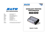
User’s Guide
Barcode Printer
MB400
Thank you for your
purchase of the SATO
MB400 barcode printer.
Make sure to read this
operation manual and
keep it in a handy place.
PN9001114
PN9001114
Introduction
Thank you for your purchase of the SATO MB400 barcode printer.
This manual helps first time users understand the basics of the printer in a short period of
time.
To get the most out of the functions of the printer, make sure to read this manual
carefully.
Warning!
1. This manual may not be reproduced in whole or in part without prior consent
from SATO.
2. The information in this manual is subject to change without notice.
3. Although this manual has been created to be as accurate as possible, contact
the shop or the dealer where you purchased this product if you find any errors
or mistakes.
Page 2
PN9001114
Features of MB400
With a compact and lightweight body and high performance, this printer prints barcodes
clearly on various types of thermal paper.
Excellent Printing Performance
Not only does this printer print barcodes clearly, but it can also enlarge and print various
types of fonts a in a free layout.
Durable and Easy to Use
This printer is also superb in durability, as it has been designed specifically for printing
barcodes. Also, special consideration has been taken so that the printer can be easily
cleaned daily.
Dispenser Function
As a portable printer, this printer can easily print and dispense labels to allow the
application of labels at site..
PN9001114
Page 3
Refernece Maintenance
Trouble
Shooting
Operation
Preparation
Table of Contents
1. Safety Precautions .................................................................... 5
Markings and Symbols ........................................................ 5
Precautions in Use............................................................... 11
2. Unpacking .................................................................................12
3. Part Names ...............................................................................13
Name and Function of Operating Parts ..............................15
4. Before Starting ..........................................................................16
Charging the Battery Pack ..................................................16
Installing and Removing the Battery Pack ..........................18
Loading Labels (Continuous mode).....................................20
Loading Labels (Dispense mode) ........................................24
Adjusting the Position of the Label Sensor ..........................25
5. Turning on the Power................................................................26
6. Starting the Printer ....................................................................27
Procedures for On-line Operation........................................28
On-line Operation ................................................................30
Using the Shoulder Belt .......................................................32
IrDA adjustment Lever .........................................................34
7. Trouble Shooting.......................................................................36
8.Daily Maintenance......................................................................38
9. Reference..................................................................................39
Optional Equipment .............................................................39
Repair Requests ..................................................................41
Service.................................................................................44
PN9001114
Page 4
Safety Precautions
Markings and Symbols
The following symbols or markings are used in this user’s guide and on the printer so
that you can properly use the printer, and to prevent any damage to property, harm or
injury to yourself and others. Make sure to read their explanations carefully to
familiarize yourself with their meanings.
Warning
Caution
This symbol indicates information that, if
ignored or applied incorrectly, creates the
danger of death or serious personal injury.
This symbol indicates information that, if
ignored or applied incorrectly, creates the
possibility of personal injury or property
damage.
Symbol example
The triangle (
) indicates something you should take absolute
care when doing. The cautions are indicated concretely within the
symbol.
A diagonal line within a circle (
not do.
A black circle (
PN9001114
) indicates something you should
) indicates something you need to do.
Page 5
Safety Precautions
In this section, safety precautions about printer operation are explained to ensure
proper care and usage. Make sure to read these carefully before using your printer.
Safety Precautions
Safety Precautions
Warning
Liquids
Do not place any containers with water or chemicals, such as
flower vases or cups, as well as small metallic objects near the
printer. Continued use creates the danger of fire or electrical
shock.
* If any of these should fall into the printer, immediately
turn off the power and contact your nearest dealer or
service center.
Foreign Matter
Do not drop or insert metallic or flammable objects into the
openings on the printer (such as outlets for cables). Continued
use creates the danger of fire or electrical shock.
* If any of these should fall into the printer, immediately
turn off the power and contact your nearest dealer or
service center.
Dropping and Damage
Do not use if the product has been dropped or damaged.
Continued use creates the danger of fire and electrical shock.
* Should the printer ever fall or otherwise become damaged,
immediately turn off the power and contact your nearest
dealer or service center.
Abnormal Conditions
Do not use the printer if it is emitting smoke or strange odors.
Continued use creates the danger of fire and electrical shock.
* Immediately turn off the power and contact your nearest
dealer or service center for repairs. Do not try to service
the printer by yourself.
PN9001114
Page 6
Disassembly
Never try to take the unit apart or modify it in any way. Doing
so creates the danger of fire or electrical shock.
* Contact your nearest dealer or Customer Service Center
for checkups, tuning and repairs.
* For checkups, tuning and repairs, contact your nearest
dealer or Customer Service Center.
Battery Pack
Never try to take apart the battery pack or modify it in any
way such as with a solder.
Doing so creates the danger of heating, fire or explosion.
Never expose the battery to direct flame, throw it into fire, or
take any actions that may lead to shorting.
Doing so creates the danger of heating, fire or explosion.
Never charge the battery pack with any other battery charger
except for the specified one.
Doing so creates the danger of heating, fire or explosion..
PN9001114
Page 7
Safety Precautions
Warning
Safety Precautions
Safety Precautions
Warning
AC Adapter / Battery Charger (Optional)
Use only the specified voltage. Using a different voltage may
create the danger of fire or electrical shock.
Never use the battery charger with any other battery pack
except for the specified one.
Doing so creates the danger of fire and electrical shock.
Never cut or damage the power cord. Also, never place heavy
objects on, set fire to or pull the power cord.
Doing so creates the danger of fire and electrical shock.
Never use a damaged cord.
Doing so creates the danger of fire and electrical shock.
* Contact your nearest dealer or service center.
Never modify, excessively bend, twist, or pull the power cord.
Doing so creates the danger of fire or electrical shock.
PN9001114
Page 8
Location
Do not locate the printer in areas subjected to high humidity
or dew.
Doing so creates the danger of electrical shock.
* If dew forms inside the printer, immediately turn off the
power and do not use it until it has dried up.
Power
Never operate the power switch, replace the battery pack or
unplug the AC adapter or battery charger with wet hands.
Doing so creates the danger of electrical shock.
Thermal Head
The thermal head becomes very hot after printing. Make sure
not touch it with bare hands.
Doing so creates the danger of injury, burns and electrical
shock.
* Take care when replacing labels after printed and when
cleaning to avoid burn.
Do not touch the edge of the thermal head with bare hands.
Doing so may cause injury.
* Take care when replacing labels or cleaning to avoid
injury.
Do not try to replace the thermal head by yourself.
Doing so creates the danger of injury, burns or electric shock.
PN9001114
Page 9
Safety Precautions
Warning
Safety Precautions
Safety Precautions
Warning
Easy Cutter
This part contains a blade. Do not touch with your bare hands,
as this may lead to injury.
Replacing the Battery Pack
Use only the specified battery pack.
When replacing the battery pack, make sure to install the pack
with the poles (+) and (–) facing the correct direction.
Incorrectly replacing the battery can rupture the battery and
create injury and damage to surrounding areas due to leakage.
When disposing of old battery packs, make sure to contact
your nearest dealer or service center.
Not using the printer for a long time
Remove the battery pack from the printer and unplug the AC
adapter from the wall outlet.
Maintenance and Cleaning
For safety during maintenance and cleaning, make sure to
remove the battery pack and the AC adapter from the printer.
PN9001114
Page 10
Do not place the printer in hot or cold places.
The operation temperature range is within 0°C to 50°C.
Do not place it in areas with himidity or temperature out of the operation range.
Do not place the printer in locations exposed to direct sunlight or places of high
temperatures.
Especially on the dashboard inside a car during summer periods, as it can get very
hot.
Use only the specified cable to connect to the external input terminal.
When connecting external equipment via the external input terminal, make sure to
use the specified cable for connection. If you have any questions, consult with your
nearest dealer or service center.
Make sure to use the specified optional equipment.
Using other equipment besides the ones specified may create damage.
Make sure to use the specified labels.
Using other types of labels besides the ones specified may cause the print head
failure or faulty printing.
PN9001114
Page 11
Safety Precautions
Precautions in Use
Unpacking
Unpacking
After opening the box, make sure that all the
printer’s accessories are included. If there are
any accessories missing, contact your nearest
dealer or service center.
1 Printer
2 Battery pack (standard or optional)
3 Shoulder belt
4 User’s guide
* The shape of the protector pads to hold the
printer in place may differ from the
picture shown.
Other accessories
Cable lock
Attached to the
interface connector.
PN9001114
Adjustment screwdriver
Located inside the printer
(under the label feed area).
Page 12
Part Names
Part Names
(1) Dispense/Continuous switch lever
Switches the print mode (dispense/
continuous).
(2) Dispenser unit
Move this when the Dispense mode
is selected.
(3) Front cover Open/Close lever
Opens and closes the front cover.
(4) Front cover
Open this for setting labels.
PN9001114
(5) Easy cutter
Cuts printed labels.
(6) Battery cover
The battery pack is inserted here.
(7) Label ejection
The printed label comes out from
here.
* Varies depending on the print mode.
(Refer to pages 20 - 24)
(8) Platen roller.
Page 13
Part Names
Part Names
Part Names
(1) Label sensor
Adjust this to the label size being
used.
(2) Label sensor adjustment dial
Use this dial to adjust the location
of the label sensor.
(3) Label guide
Adjust this to the label size being
used.
(4) O ring
Use this when fixing the position of
the label guide.
Page 14
(5) Shoulder belt hook
Attaches the shoulder belt when
hanging the printer on shoulder.
(6) Adjustment screwdriver
(supplied accessory)
(7) IrDA filter
The IrDA receiving element is
located inside.
(8) IrDA adjustment lever
Changes the angle of the IrDA
receiving element.
PN9001114
Part Names
Operation part names
POWER key
Turns the power on and off.
PRINT key
Sets the printer to on-line or off-line.
STATUS LED indicator
Indicates the status of the printer.
(Refer to pages 28, 29, 36 and 37)
Feeds labels.
BATTERY LED indicator
Indicates the status of the battery.
(Refer to pages 19, 36 and 37)
(9) Interface cover
(11)DC input jack cover
FEED key
Covers the interface connector. (The
cable lock is included.)
(10)Interface connector (RS-232C)
Connects to a computer.
PN9001114
Covers the DC input jack when not
in use.
(12)DC input jack
Connects the AC adapter.
Page15
Before Starting
Charging the Battery Pack
Before Starting
You can recharge the battery pack by inserting it into the battery charger (optional).
(1) Plug one end of the AC
adapter into the battery
charger and the other
end into the wall outlet.
(2) Insert the battery pack. Make sure the
connector on the battery pack is facing down and insert it into the
charger.
• The CHARGE indicator lights in red
when charging starts.
• The CHARGE indicator lights in green
when charging is complete (Fully
charged).
(3) When charging is complete, remove
the battery pack from the charger.
Page 16
PN9001114
• If the CHARGE indicator on the charger does not light up, make sure that the
battery pack is firmly attached to the charger. The battery may not charge, if not
firmly attached.
• If an already charged battery pack is inserted into the charger, the CHARGE
indicator will turn red once (charging), however it will soon change to green
(fully charged).
• If charging a battery pack that has not been used for a long period, the CHARGE
indicator will flash for a while. This does not indicate an error, and you can
continue charging as it is. If the indicator continues to flash for a long time while
charging, replace the battery pack with a new one.
• The battery pack can be charged up to 300 times (during use in regular temperatures). If the battery pack is fully charged but soon runs out, replace the battery
pack with a new one.
* Write down the date of purchase of the battery with a
marker on the sticker attached to battery pack as a
guideline of the number of times the battery can be
recharged (the life of the battery). (For example: Date of
purchase: Sep. 1st, 2000.)
• The battery pack cannot be used when using the AC
adapter. If the AC adapter jack is plugged into the printer
when using the battery, the power will be reset. (If there is any remaining print
data, it will be lost.)
Charging time
The charge time for one battery pack from empty until fully charged is about 90
minutes. For two battery packs, it takes about 130 minutes. (The charging time
varies depending on the environment.).
PN9001114
Page 17
Before Starting
Notice
Before Starting
Installing and Removing the Battery Pack
Before Starting
(1) Place your finger on the battery
cover ribbed area, and open the
battery cover in the direction of the
arrow.
(2) Insert the battery pack.
Insert the battery pack with the connector
facing towards the end.
* Insert the battery all the way in until the
lock clicks into place.
(3) To remove the battery pack, press
down the lock lever and release the
lock. Then pull the battery pack out
placing your finger into the notch.
Notch.
Take care not to drop the
battery pack when removing
it. The battery pack may be
damaged if it is dropped.
Page 18
PN9001114
2. Low Battery Error
When the battery gets empty, a low battery error is detected and the BATTERY
LED indicator lights up in red. The keys cannot be operated, and after 30 seconds
the power automatically turns off. Make sure to recharge the battery.
Status
BATTERY LED indicator
Battery near end
Light (orange)
Low battery error
Light (red)
The BATTERY LED indicator does not light up during printing or an error, even
if battery near end or low battery error has been detected.
Caution!
• Make sure to turn the power off before removing or replacing the battery
pack.
• If you do not plan to use the printer for long period of time, make sure to
remove the battery pack.
If not removed, the battery may get over-discharged and may not be recharged.
• Do not store the battery in places of high temperature.
PN9001114
Page 19
Before Starting
Battery Status
1. Battery near end
When the battery is getting low, the battery near end is detected and the
BATTERY LED indicator lights up in orange. The keys can still be operated,
however the battery should be recharged.
Before Starting
Loading Labels
... The method of loading the labels may vary depending
on the print mode.
Before Starting
[Continuous Mode]
Labels
non-dispensed labels
adhesive backed labels
Core-less rolls
(1) Press the cover Open/Close lever in
the direction of the arrow to release
the front cover lock.
(2) Slide the front cover to open.
Hold the front cover and slide it in the
direction of the arrow until it stops.
Page 20
PN9001114
Before Starting
(3) Open the front cover in the direction
of the arrow.
(4) Insert the label roll on the label guide
boss inside the front cover.
• Press the tab for adjusting the label guide
(right), and adjust the guide to the width of
the labels to be used.
Label guide boss
• Firmly insert the label roll on the bosses on
the left and right of the label guide.
* Move the label roll to make sure that it is
firmly set on the bosses.
(Continued to page 22)
PN9001114
Page 21
Before Starting
... The method of loading the labels may vary depending
on the print mode.
Loading Labels
Before Starting
[Continuous Mode] (Continued from page 21)
(5) After peeling the lead tape on the roll,
take the leading edge of the first label on
the roll and pull it out via the platen
roller. Then turn the front cover in the
direction of the arrow.
(6) Close the front cover in the direction
of the arrow.
* Press the front cover until the cover
Open/Close lever clicks.
If the cover is not properly
locked, the warning label in
the front cover Open/Close
lever can be seen.
* Never print with the cover
not properly locked.
Front cover Open/
Close lever
Locked
Page 22
Warning label
Not locked
PN9001114
Core-less rolls
Before Starting
After removing both of the label guide bosses
on the sides with the driver (attached
accessory), set the roll by following the
directions 4, 5 and 6 on page 21 to 22. 4 5
Label guide boss
Setting the Label Guide Boss
If the width of the label is fixed, the boss can be fixed.
• After setting the roll on the label guide,
fix it in place by sliding the “O-ring” on
the bottom left to the edge of the label
guide.
* Setting labels will be easier when the
label guide is fixed.
* When using core-less paper, the label
guide must be always fixed.
The “O-ring”
Above are the steps for setting the papers during the Continuous mode.
PN9001114
Page 23
Before Starting
... The method of loading the label may vary depending on
the print mode.
Loading Labels
Before Starting
[Dispense Mode]
Labels
First perform the procedure steps 1 through 6 on pages 22 and 23 (Continuous mode).
• Pick the Dispense/Continuous switch
lever from both sides, and slide the
Dispenser unit to the direction of the
arrow.
* Leave more than 30mm of the label out
for the Dispense mode.
*
Slide the Dispenser unit until it is set in place.
Page 24
PN9001114
Adjusting the Position of the Label Sensor
Before Starting
(1) Moving the Label Sensor to the
Right
Turn the Label Sensor Adjustment
Dial up.
(2) Moving the label Sensor to the Left
Turn the Label Sensor Adjustment
Dial down.
The Label Sensor Adjustment Dial
Using the Sensor
Align the right edge of the sensor with the
right edge of the label.
Label
PN9001114
Page 25
Turning on the Power
After preparations, turn on the power.
Turning on the Power
• Press the POWER Key
The STATUS LED indicator lights up in
green.
* Press the power key again to turn the
power off. The STATUS LED indicator
goes out and the power turns off.
Caution!
• Make sure you turn off the power before taking out or changing the
battery pack.
The STATUS LED indicator lights up in green when the power is turned off.
While this light is on, do not remove the battery pack. Always make sure the
STATUS LED indicator is off before taking out the battery pack.
• If the battery pack is removed after the power is turned off, but with the
STATUS LED indicator still lit up in green, the printer may not refresh
the data in memory
Page 26
PN9001114
Starting the Printer
Continuous Printing
Test Printing
Printing in Printer condition
Dispense Printing
Continuous Printing
On-line Printing
Printing in Printer
condition Dispense
Printing
Continuous Printing
PN9001114
Dispense Printing
Dispense Printing
Page 27
Starting the Printer
There are two modes for printing: the Continuous mode and the Dispense mode. Test
printing and On-line printing can be done on both modes.
Starting the Printer
Procedures for On-line Operation
Starting the Printer
Normal Printing Mode
The STATUS LED indicator during the Normal Printing mode is as shown on the
table below.
Action
Normal Printing Mode
On-line
Off-line
Status (LED)
On (Green)
On (Green)
Off
Power Save Mode
1. Sleep Mode
The printer will go into the Sleep mode if not performed any operation for 5
seconds. Pressing the PRINT key or the FEED key, or receiving data will
resume normal status.
Page 28
PN9001114
Starting the Printer
Test Printing Mode (FEED key + POWER ON)
The STATUS LED indicator during the Test Printing mode is as shown on the table
below.
Action
Starting Test Print Mode
Test Print Mode ON
Test Print Mode (printing)
Suspension
Status (LED)
ON (Red/Green)
On (Green)
On (Green)
Off
2. Auto Power Off Mode
The printer will go into the Auto Power Off Mode if not operated for 5
minutes. Be careful as the printing data, if any, will not be saved.
PN9001114
Page 29
Starting the Printer
On-line Operation
Starting the Printer
Open the interface cover, and proceed by the following directions.
(1) Plug in the interface cable as shown.
• Only use the specified cables.
(2) Put on the cable lock to prevent the plug
from falling out.
• Push the protrusion of the cable lock into
the hole indicated.
(3) Check the DIP switch setting (for
transmission conditions).
* The setup should be done with the screw driver
(attached accessory).
Page 30
PN9001114
Switch
No.
Interface setup
1-1
1-1 1-2 1-3
OFF OFF OFF
1-2
ON OFF OFF
OFF ON OFF
ON ON OFF
1-3
OFF OFF ON
ON OFF ON
OFF ON ON
ON
1-4
1-5
ON
ON
Function
Action
RS-232C
TTL
IrDA transmission
Short range radio transmission
(optional)
RS-232C, IrDA transmission
TTL, IrDA transmission
RS-232C, Short range radio
transmission(optional)
TTL, Short range radio
transmission(optional)
The automatic feed function
OFF : Press FEED key
ON : After closing the cover, the automatic feed
function starts.
Head Check
OFF : Head check is not in effect.
ON : Head check is in effect.
1-6
Unavailable for use
1-7
Unavailable for use
1-8
Unavailable for use
Initial Factory
Default Setting
DSW1-1
OFF
DSW1-2
OFF
DSW1-3
OFF
DSW1-4
OFF
DSW1-5
ON
DSW1-6
OFF
DSW1-7
OFF
DSW1-8
OFF
Make sure the power is turned off before setting up the DIP switch.
• Unless directed otherwise, do not change the setup.
PN9001114
Page 31
Starting the Printer
Setting up the DIP switch
Starting the Printer
Using the Shoulder Belt
Starting the Printer
Use the shoulder belt to leave both of your hands free when using the printer while
moving. Follow the directions below.
Attaching the Shoulder Belt
(1) Fasten the pin onto the hook as
indicated.
(2) Using the screwdriver (accessory),
push in the head of the pin and lock it
in place.
(3) Pull the shoulder belt gently and
make sure the belt is secured onto the
printer.
* Press the head of the pin to remove the
belt.
Page 32
PN9001114
Starting the Printer
Example of using the shoulder belt
Wiring the Interface Cable
An indentation is provided at the
foot of the printer for the interface
cable. Using this prevents the jack
from falling out of the plug or damaging the cords, and keeps the cable
in place. Wire the cable as shown, in
relevance to the shoulder, which the
printer is hung on.
PN9001114
Page 33
Starting the Printer
IrDA adjustment Lever
Starting the Printer
By adjusting the angle of the lever, the angle of the IrDA receiving element can be
changed.
• Use the rib of the IrDA adjustment lever to adjust the angle.
* Check the angle by where the IrDA adjustment lever is facing.
Page 34
PN9001114
Starting the Printer
IrDA transmission Range
The IrDA allowable distance is 10 to 20 cm.
* Varies from the environment where printer is used. Under direct sunlight or
strong lighting, it may not be possible to make IrDA transmittal. Should this
happen, cover the IrDA filter to interrupt the light, or bring the IrDA filters to
contact together.
PN9001114
Page 35
Trouble Shooting
Trouble Shooting
The status of the printer is indicated on the STATUS LED indicator. Abnormalities
of the status is indicated as below. To solve the problems, follow the directions in
the table.
STATUS (LED)
Red
Mode
After power input
Details
1 Program error
2 FLASH ROM error
Open cover
Red (blinking)
On-line
Paper end
Sensor error
Red / orange (blinking)
On-line
Buffer over
Orange (blinking)
On-line
Head error
Orange/ green (blinking)
On-line
Head overheating
protection function
Green (blinking)
On-line (Printing/
Receiving data)
Buffer near full
STATUS (LED)
Red (blinking)
Mode
All modes
Details
Low battery
Page 36
PN9001114
Cause
Solution
FLASH ROM reading/writing error
1. Replace the flash ROM.
2. Download the program again.
1. Cover isn’t locked.
1. Lock the cover.
2. Cover micro switch is not working 2. Adjust the micro switch.
properly.
Out of paper
Load new labels
1.
2.
3.
4.
1.
Sensor level isn’t accurate.
Sensor type doesn’t match.
Label is wandering.
Sensor position isn’t accurate.
Received data over the buffer
quota.
2. The protocol between the printer
and host doesn’t match.
The head is broken
1.
2.
3.
4.
1.
Not an error. The over heating
protection function activates when
the head temperature rises above
70°C.
You are approaching the quota on the
buffer.
The function will deactivate when the
head temperature goes down to 60°C.
Cause
Solution
Batteries haven’t been recharged
properly
Recharge the battery.
Adjust the sensor level.
Adjust the sensor type.
Reset the labels properly.
Adjust the position of the sensor.
Adjust the data amount at the host
side so that it won’t exceed the
buffering quota.
2. Match the protocol.
Replace the head
Pause the data transmission and wait
till the buffer is empty before trying
again.
* Please consult your nearest Customer Service Center or dealer.
PN9001114
Page 37
Trouble Shooting
The power will automatically be turned off 30 seconds after low battery is indicated.
Make sure the power is off before removing the battery pack, and recharge the
battery.
Daily Maintenance
Daily Maintenance
After pressing the POWER key to turn the printer off and removing the battery pack,
follow the directions below.
• Press the Front cover Open/ Close
lever and open the front cover.
Thermal Head
Thermal Head
Wipe clean with cloth and alcohol.
Platen Roller
Wipe clean with cloth and alcohol.
Platen Roller
Dispense Roller
Wipe clean with cloth and alcohol.
Dispense Roller (behind the Dispenser unit)
Do not use thinners,
benzene, or kerosene.
Page 38
PN9001114
Reference
Optional Equipment
Reference
Battery Pack (Standard or optional)
Used when the printer is carried
AC Adapter, Battery charger
Read the guide for instructions and
precautions.
Battery Charger
The battery packs are recharged on this.
AC Adapter for Printer
Use the adapter to supply power from a
household electrical outlet (110VAC).
Connect the DC output jack of the adapter
to the printer.
Caution!
• Always use the specified adapter.
• Before plugging or unplugging the AC adapter, always make sure the printer is
turned off.
• Always hold the printer when pulling out or plugging in the jack.
• Be careful not to damage the cords.
• Store away in a safe place if not used.
PN9001114
Page 39
Reference
Optional Equipment
Reference
RS-232C cable
For connection of computers and
handheld terminals.
Short range radio unit
For communication with specified handy
terminal.
Battery Charger Set
Battery charger enables the recharging of
the maximum of 4 batteries at the same
time, with one AC adapter.
Page 40
PN9001114
• Always attach to the printer a sample of the defective print and note the functional
problem before sending it out when requesting for repairs.
• After repairs have been made, you may be asked to recover the format of the
printer by yourself.
PN9001114
Page 41
Reference
When ordering repairs
Reference
Basic Specifications
Reference
Items
Printing System
Head Density
Maximum Printing Size Width
Printing Speed
Printing Mode
Size
Weight
Power (Battery)
Paper
Label Shape
Label Size
Width: 50- 11mm (53-114mm)
Pitch (Continuous): 25-297mm (28-300mm)
Pitch (Dispense): 25-182mm (28-185mm)
Numbers indicated in ( ) are for pasteboards,
non-adhesive or non-separated labels, and
journal paper.
Continuous: 0.06 – 0.18mm
Dispense: 0.18mm (the thickness of the
pasteboard is under 0.06mm)
Thickness
Self Diagnosing Function
Power Save Function
Interface
Page 42
Details
Thermal
8 Heads/mm
104mm × Pitch 297mm
Max. 50mm/sec. (may vary from environment)
Continuous, Dispense, and Journal
Printer : W190mm × D 80mm × H 139mm
Approximately 960g (including battery)
Packet type (Lithium ion battery); 1600mAh;
Will print 1 roll of journal paper (25m roll) on
continuous mode when fully charged (printing
rate at 15% or less)
Always use specified labels
Roll; Maximum outer diameter: 58mm
RS232C/ TTL
Optical Coupler
Radio (option)
Battery Check / Paper end
Head Open/ Test Printing / Head Check
Into the Sleep mode after 5 seconds without any
operation, and the Auto power off mode after 5
minutes without any
operation.
High density special connecter
IrDA (IrDA Standard Ver.1.2 compliant)
Short range radio module
PN9001114
Label Sensor
Details
Eye-Mark sensor / Dispense sensor
Font
SATO standard font: × 21, × 22, × 23,
Kanji 16 × 16, 24 × 24 Kaku Gothic / Mincho (JIS
First/Second standard)
Barcode
JAN8/13, UPC-E/UPC-A, CODABAR,
CODE39, INTERLEAVED 2 of 5, CODE 128,
CODE 93, Customer Bar Code
PDF 417, QR code
POWER key, PRINT key, FEED key
STATUS, BATTERY (Red/ Orange/ Green)
Noise radiation: VCCI -B
Static withstanding pressure: Level 2
Suspension of action upon detection of low
batteries.
Operation temperature: 0-50°C
Humidity: 25-80% (without condensation)
Two Dimension Code
Function Key
LED
Noise Gauge
Protection Function
Environment Conditions
(including battery)
Storage Temperature: –10 - 60°C
Option
PN9001114
Humidity: 25-80% (without condensation)
AC adapter, Battery charger, Battery pack, RS232C cable, Short range radio module
Page 43
Reference
Items
Reference
Service
Reference
To ensure that our products are used at their best, we provide repair and maintenance
services through a network of authorized SATO Service Centers or factory direct.
Please contact SATO Technical support via one of the following methods for
instructions on returning units for repair.
Email: [email protected]
Telephone: (704) 644-1660
Fax: (704) 644-1662
Stored Data
The data and softwares entered in the printer may be lost during repair. We
recommend making back-up prior to repair. Make sure to check the printer for its
data after repair.
Page 44
PN9001114
PN9001114
SATO America, Inc.
10350A Nations Ford Road
Charlotte NC 28273
www.satoamerica.com
PN9001114