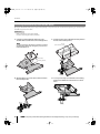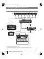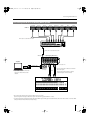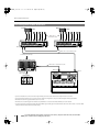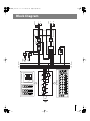
1
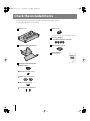
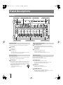
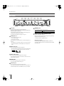
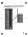
M-48_e.book 1 ページ 2009年2月24日 火曜日 午前9時33分
Owner’s Manual
Before using this unit, carefully read the sections entitled: “USING THE UNIT SAFELY”
and “IMPORTANT NOTES” (p. 5–6; p. 7). These sections provide important information
concerning the proper operation of the unit. Additionally, in order to feel assured
that you have gained a good grasp of every feature provided by your new unit,
Owner’s Manual should be read in its entirety. The manual should be saved and kept
on hand as a convenient reference.
Copyright © 2009 ROLAND CORPORATION
All rights reserved. No part of this publication may be reproduced in any form without
the written permission of ROLAND CORPORATION.
M-48_e.book 2 ページ 2009年2月24日 火曜日 午前9時33分
Introduction
Check the included Items
The following items are included with the M-48. Make sure that all of these items are present.
If anything is missing, please contact your dealer.
M-48 (main unit)
Ferrite core (1)
* Attach this to the REAC cable or Cat5e Ethernet cable (p. 15).
Screws for attaching
the APC-33 all purpose clamp (4)
Mounting bracket/bracket tray (1)
REAC connector cover (1)
Owner’s Manual
(this document)
Mounting bracket attachment kit
Rubber washer (1)
Wing nut: for 3/8 inch screw (1)
Washers: for 3/8 inch screw (2)
Nut: for 5/8 inch screw (1)
Screws for fastening the M-48 (2)
2
M-48_e.book 3 ページ 2009年2月24日 火曜日 午前9時33分
Main Features
● The flexibility of 40-channel mixing with easy operation enabled by grouping
The M-48 allows you to mix up to 40 channels of digital audio sent via REAC.
You can individually adjust the level and pan of 40 source channels and then assign the 40 sources to 16 stereo groups for
convenience.
Volume adjustments on the M-48 are performed on group mixes assigned to each knob, making adjustments extremely quick
and easy.
* Settings by the mixing engineer are done from the screen of the M-400 V-Mixer when the M-48 is part of a V-Mixing System. If the
M-48 is connected an alternative mixing console, its settings can be edited from a computer connected to the S-4000 or S-1608 systems.
* In order to edit the M-48’s settings from the M-400, version 2.0 or later system software is required.
* In order to edit from a computer connected to the S-4000 or S-1608 systems, the S-4000 system must have system software version 2.1 or
later, and the S-1608 system must have system software 2.0 or later. Version 2.0 or later of the S-4000 RCS application software (Windows XP/
Vista supported) is also required.
System software for each unit and the S-4000 RCS application software can be downloaded at no cost from the Roland Systems Group
website (http://www.rolandsystemsgroup.net).
● Unique setups for each musician
Each M-48 on the stage or in the studio can have their own setup.
For example, the drummer’s setup can have each drum mic assigned to its own group (knob), while the keyboard and vocalist
audio is combined into a single group. Meanwhile, the vocalist’s setup can combine the drum mics into a single group, while
the keyboard and vocal mics each have their own groups.
Musicians do not need to make any compromise in their own monitor setup. Since grouping assignments are per M-48, there’s
also no need to use up multiple buses in the mixing console for stage sends, allowing the mixing console to now be used more
flexibly.
● Superior sound to support the musician
In order to deliver natural-sounding and comfortable monitor sound, the M-48 provides reverb and 3-band EQ. Since these can
be set individually for each group, the musician can obtain their own ideal personal mix.
A limiter is provided to address the problem of excessive volume that can cause discomfort particularly when using
headphones. This could mitigate hearing damage that can be caused by sudden high volumes.
An ambient mic with volume control is also provided. This allows the audience’s response to be audible even when wearing
headphones. It also allows convenient communication between the musicians on stage or in the studio.
● Connections with external devices
The M-48 can be simultaneously connected to headphones and speakers. You can listen to the monitor sound through
headphones while outputting just the low frequencies from a floor monitor so that they can be felt by the entire body.
The rear panel provides an AUX input jack and output jacks for recording. A rhythm machine or metronome can be connected
to the AUX input jack so that the musician can conveniently perform start/stop operations or control the tempo. Additionally,
by connecting a portable audio recorder (such as one from the EDIROL R-09 series) to the recording output jack, you can record
the monitor sound you’re hearing on stage. This lets you take home the recorded monitor sound and use it for practice.
* After the power is turned on (p. 20), audio will not be output until the REAC connection is established.
● No need for AC power cord or AC adaptor
REAC EMBEDDED POWER means that power is supplied from the S-4000D via the REAC cable. No need for an AC power cord or
AC adaptor means a less cluttered setup.
* REAC EMBEDDED POWER is technology that uses a Cat5e cable to supply power as well as the REAC audio signals to a REAC device.
REAC devices that support REAC EMBEDDED POWER do not require an AC adaptor or AC power cord for their power supply; simply
connecting the REAC cable will allow REAC communication as well as supply the power.
● Connect with many types of systems for a variety of uses
In addition to using the M-48 with full-digital connections as part of the RSS V-Mixing System, you can also connect it to a
conventional mixing console via the stage unit of a digital snake. From small-scale to large-scale, analog or digital, you can
connect and use the M-48 with a wide range of sound mixing systems.
Using the M-48 as part of the V-Mixing System allows full-digital transmission via REAC (Roland Ethernet Audio
Communication), delivering high-quality monitor sound to the musicians on stage or in the studio.
* Connections with an alternate mixer require the S-4000 system or S-1608 system.
3
M-48_e.book 4 ページ 2009年2月24日 火曜日 午前9時33分
Table of Contents
Please read before using.
USING THE UNIT SAFELY ...................................................................................................... 5
IMPORTANT NOTES................................................................................................................ 7
Introduction
2
Check the included Items........................................................................................................................................................................................... 2
Main Features ................................................................................................................................................................................................................. 3
Panel Descriptions
8
Top Panel.......................................................................................................................................................................................................................... 8
Rear Panel....................................................................................................................................................................................................................... 10
Installation
11
Placing the M-48 on a Desk at an Angle .............................................................................................................................................................11
Attaching the M-48 to the Top of a Mic Stand..................................................................................................................................................11
Attaching the M-48 to Any Part of a Mic Stand ................................................................................................................................................14
Attaching the REAC Connector Cover .................................................................................................................................................................15
Attaching the Ferrite Core........................................................................................................................................................................................15
Connecting External Devices
16
Connecting the M-48 to a V-Mixing System ......................................................................................................................................................16
Connecting the M-48 to an Analog Mixer System ..........................................................................................................................................17
Connecting Nine or More M-48 Units ..................................................................................................................................................................18
Connecting Input/Output Devices to the M-48 ...............................................................................................................................................19
Turning the Power On/Off (REAC EMBEDDED POWER Supported) ..........................................................................................................20
Making Settings for the M-48
21
40-channel Mixer Settings and Operation .........................................................................................................................................................21
Default Values of the Settings.................................................................................................................................................................................22
Example Setups............................................................................................................................................................................................................ 23
Adjusting the Mix
26
Adjusting the Volume of Each Group ..................................................................................................................................................................26
Listening to Each Group Individually (Solo).......................................................................................................................................................26
Adjusting the Pan of Each Group ..........................................................................................................................................................................27
Adjusting the Input Level of AUX IN.....................................................................................................................................................................27
Using the Built-in Ambient Mic ..............................................................................................................................................................................27
Using Effects
28
Applying Reverb to Each Group.............................................................................................................................................................................28
Applying EQ to Each Group .....................................................................................................................................................................................28
Headphones Output and Line Out Adjustments
29
Adjusting the Headphones Output Level ..........................................................................................................................................................29
Adjusting the Headphones Output Tone ...........................................................................................................................................................29
Applying a Limiter to the Headphones Output ...............................................................................................................................................29
Adjusting the Line Out Output Level ...................................................................................................................................................................29
Using the Memory Functions
30
About Memory ............................................................................................................................................................................................................. 30
Storing Mixer Settings to Memory (Store)..........................................................................................................................................................30
Recalling Mixer Settings from Memory (Recall)................................................................................................................................................31
Returning to the Factory Settings (Factory Reset)...........................................................................................................................................31
Appendices
32
Main Specifications..................................................................................................................................................................................................... 32
Dimensions .................................................................................................................................................................................................................... 32
Block Diagram............................................................................................................................................................................................................... 33
Troubleshooting .......................................................................................................................................................................................................... 34
4
M-48_e.book 5 ページ 2009年2月24日 火曜日 午前9時33分
USING THE UNIT SAFELY
The
symbol alerts the user to important instructions or
warnings.The specific meaning of the symbol is
determined by the design contained within the triangle. In
the case of the symbol at left, it is used for general
cautions, warnings, or alerts to danger.
Used for instructions intended to alert the
user to the risk of death or severe injury
should the unit be used improperly.
Used for instructions intended to alert the
user to the risk of injury or material
damage should the unit be used
improperly.
The
symbol alerts the user to items that must never be
carried out (are forbidden). The specific thing that must
not be done is indicated by the design contained within
the circle. In the case of the symbol at left, it means that
the unit must never be disassembled.
* Material damage refers to damage or
other adverse effects caused with
respect to the home and all its
furnishings, as well to domestic animals
or pets.
The ● symbol alerts the user to things that must be
carried out. The specific thing that must be done is
indicated by the design contained within the circle. In the
case of the symbol at left, it means that the power-cord
plug must be unplugged from the outlet.
010
When used in combination with headphones, amps, or speakers, this device is capable of producing
volume levels that may cause permanent hearing loss. Do not use this device at high volumes for an
extended period of time. If you should experience any loss of hearing or ringing in your ears, you should
immediately stop using this product, and consult a medical professional.
002a
● Do not open or perform any internal modifications on
the unit.
.................................................................................................................................
003
004
● Never install the unit in any of the following locations.
• Subject to temperature extremes (e.g., direct
sunlight in an enclosed vehicle, near a heating
duct, on top of heat-generating equipment); or are
● Do not attempt to repair the unit, or replace parts
within it (except when this manual provides specific
instructions directing you to do so). Refer all servicing
to your retailer, the nearest Roland Service Center, or
an authorized Roland distributor, as listed on the
“Information” page.
• Humid; or are
.................................................................................................................................
• Exposed to rain; or are
• Damp (e.g., baths, washrooms, on wet floors); or
are
• Exposed to steam or smoke; or are
• Subject to salt exposure; or are
• Dusty or sandy; or are
• Subject to high levels of vibration and shakiness.
.................................................................................................................................
5
M-48_e.book 6 ページ 2009年2月24日 火曜日 午前9時33分
USING THE UNIT SAFELY
006
● When using the unit with a mic stand, the rack or
stand must be carefully placed so it is level and sure
to remain stable. If not using a mic stand, you still
need to make sure that any location you choose for
placing the unit provides a level surface that will
properly support the unit, and keep it from wobbling.
.................................................................................................................................
011
● Do not allow any objects (e.g., flammable material,
coins, pins); or liquids of any kind (water, soft drinks,
etc.) to penetrate the unit.
.................................................................................................................................
012d
● Immediately turn the power off, and request
servicing by your retailer, the nearest Roland Service
Center, or an authorized Roland distributor, as listed
on the “Information” page when:
• If smoke or unusual odor occurs
• Objects have fallen into, or liquid has been spilled
onto the unit; or
• The unit has been exposed to rain (or otherwise
has become wet); or
• The unit does not appear to operate normally or
exhibits a marked change in performance.
101c
● This device is designed so that it can be used with a
microphone stand or with the APC-33 all-purpose
clamp made by Roland. When using this device with
a mic stand or the all-purpose clamp, placing it on an
unstable location may cause the device to topple or
fall, possibly damaging the device or causing
personal injury.
.................................................................................................................................
101f
● Even if you observe the cautions listed in the owner’s
manual, certain modes of use may produce the
potential for this device to fall from the mic stand, or
for the mic stand to topple over. Please exercise
caution before using this product.
.................................................................................................................................
new
● When attaching or detaching the mounting bracket
or bracket tray (p. 11–14), be careful not to injure
yourself on the corners of the bracket or tray.
.................................................................................................................................
104
● Try to prevent cords and cables from becoming
entangled. Also, all cords and cables should be
placed so they are out of the reach of children.
.................................................................................................................................
106
● Never climb on top of, nor place heavy objects on the
unit.
.................................................................................................................................
.................................................................................................................................
013
108c
● When using this device in an environment where
children are present, an adult should provide
supervision until the child is capable of following all
the rules essential for the safe operation of the unit.
.................................................................................................................................
014
● Protect the unit from strong impact.
(Do not drop it!)
.................................................................................................................................
● Disconnect all cords coming from external devices
before moving the unit.
.................................................................................................................................
118c
● Keep small parts such as the following out of reach of
children so that they cannot be accidentally
swallowed.
• Removed parts:
Screws for fastening the bracket tray
• Included items:
Ferrite core, REAC connector cover, Wing nut, Nut,
Washers, Rubber washer, Screws for fastening the M-48,
and Screws for attaching the APC-33 all purpose clamp
.................................................................................................................................
6
M-48_e.book 7 ページ 2009年2月24日 火曜日 午前9時33分
IMPORTANT NOTES
Power Supply
307
● Before connecting this unit to other devices, turn off the
power to all units. This will help prevent malfunctions and/or
damage to speakers or other devices.
Placement
351
● Using the unit near power amplifiers (or other equipment
containing large power transformers) may induce hum. To
alleviate the problem, change the orientation of this unit; or
move it farther away from the source of interference.
Repairs and Data
452
● Please be aware that all data contained in the unit’s memory
may be lost when the unit is sent for repairs. Please save
important data as a file on the M-400 or on your computer. For
details on how to save data, refer to the owner’ manual of the
M-400 (Ver. 2.0 or later) or the S-4000 RCS Ver. 2.0. During
repairs, due care is taken to avoid the loss of data. However, in
certain cases (such as when circuitry related to memory itself
is out of order), we regret that it may not be possible to restore
the data, and Roland assumes no liability concerning such loss
of data.
352a
● This device may interfere with radio and television reception.
Do not use this device in the vicinity of such receivers.
352b
Additional Precautions
551
354a
● Please be aware that the contents of memory can be
irretrievably lost as a result of a malfunction, or the improper
operation of the unit. To avoid inconvenience in the event of
data loss, save important data as a file on the M-400 or on your
computer. For details on how to save data, refer to the owner’s
manual of the M-400 (Ver. 2.0 or later) or the S-4000 RCS
Ver. 2.0.
355b
● Unfortunately, it may be impossible to restore the contents of
data that was stored on the unit, the M-400, and your
computer once it has been lost. Roland Corporation assumes
no liability concerning such loss of data.
● Noise may be produced if wireless communications devices,
such as cell phones, are operated in the vicinity of this unit.
Such noise could occur when receiving or initiating a call, or
while conversing. Should you experience such problems, you
should relocate such wireless devices so they are at a greater
distance from this unit, or switch them off.
● Do not expose the unit to direct sunlight, place it near devices
that radiate heat, leave it inside an enclosed vehicle, or
otherwise subject it to temperature extremes. Excessive heat
can deform or discolor the unit.
● When moved from one location to another where the temperature and/or humidity is very different, water droplets
(condensation) may form inside the unit. Damage or
malfunction may result if you attempt to use the unit in this
condition. Therefore, before using the unit, you must allow it
to stand for several hours, until the condensation has
completely evaporated.
360
● Depending on the material and temperature of the surface on
which you place the unit, its rubber feet may discolor or mar
the surface.
You can place a piece of felt or cloth under the rubber feet to
prevent this from happening. If you do so, please make sure
that the unit will not slip or move accidentally.
552
553
● Use a reasonable amount of care when using the unit’s
buttons, sliders, or other controls; and when using its jacks
and connectors. Rough handling can lead to malfunctions.
556
● When connecting / disconnecting all cables, grasp the
connector itself—never pull on the cable. This way you will
avoid causing shorts, or damage to the cable’s internal
elements.
559a
● When you need to transport the unit, package it in the box
(including padding) that it came in, if possible. Otherwise, you
will need to use equivalent packaging materials.
Maintenance
401a
● For everyday cleaning wipe the unit with a soft, dry cloth or
one that has been slightly dampened with water. To remove
stubborn dirt, use a cloth impregnated with a mild, nonabrasive detergent. Afterwards, be sure to wipe the unit
thoroughly with a soft, dry cloth.
402
● Never use benzine, thinners, alcohol or solvents of any kind, to
avoid the possibility of discoloration and/or deformation.
* Microsoft and Windows are registered trademarks of Microsoft Corporation.
* Windows® is known officially as: “Microsoft® Windows® operating system.”
* Neutrik and EtherCon are registered trademarks of Neutrik, Inc.
* MMP (Moore Microprocessor Portfolio) refers to a patent portfolio concerned with microprocessor architecture, which was
developed by Technology Properties Limited (TPL). Roland has licensed this technology from the TPL Group.
7
M-48_e.book 8 ページ 2009年2月24日 火曜日 午前9時33分
Panel Descriptions
Top Panel
Memory section
Supplementary input section
Layer select section
Line out section
Group control section
Layer select section
Headphones section
Control select section
Group control section (continued)
Here you can select the layer for the groups that you want to operate.
The button corresponding to the currently shown layer will light.
SIG (signal) indicators
These will light when the group contains a source whose level
exceeds -40 dB. This indicates the level of the source immediately
after the REAC input.
[1-8] button
Selects groups 1–8.
[SOLO] buttons
[9-16] button
These turn Solo on/off for each group.
Selects groups 9–16.
The button will blink when Solo is on.
* If the button of the layer not shown is blinking, this means that
Solo is turned on for a group in that layer.
☞ “Listening to Each Group Individually (Solo)” (p. 26)
Control select section
Group control section
Here you can mix the groups.
* The [CONTROL] knobs, SIG indicators, and [SOLO] buttons of unused
groups (no sources assigned) will not do anything.
Here you can select the parameter that will be adjusted by the [Control]
knobs of the group control section.
The button of the selected parameter will light.
[Control] knobs
[VOLUME] button
These adjust the parameter selected in the control select section.
This button allows you to adjust the volume.
The volume can be adjusted in a range of -Inf dB – +20.0 dB.
The indicators around the circumference of the [Control] knobs
indicate the approximate value of the parameter you’re adjusting.
When the indicator at the 6 o’clock position is lit, the
following values are indicated.
[PAN] button
This allows you to adjust the pan.
• Volume/Reverb send/EQ gain: 0.0 dB
• Pan: center
☞ “Adjusting the Volume of Each Group” (p. 26)
Lit
☞ “Adjusting the Pan of Each Group” (p. 27)
[REVERB SEND] button
This button allows you to adjust the reverb send.
The reverb send can be adjusted in a range of -Inf dB – +10.0 dB.
☞ “Applying Reverb to Each Group” (p. 28)
8
M-48_e.book 9 ページ 2009年2月24日 火曜日 午前9時33分
Panel Descriptions
Control select section (continued)
[LO GAIN] button
Line out section
In this section you can adjust the output level of the line out.
This button allows you to adjust the EQ low gain.
LINE OUT [VOLUME] knob
The low gain (center frequency 120 Hz) can be boosted or cut by up
to 15 dB.
This knob adjusts the line out output level.
☞ “Applying EQ to Each Group” (p. 28)
[MID FREQ] button
This button allows you to adjust the EQ mid frequency
The center frequency of the mid frequency can be adjusted in a
range of 20 Hz–20.0 kHz.
☞ “Applying EQ to Each Group” (p. 28)
[MID GAIN] button
This button allows you to adjust the EQ mid gain.
The mid gain can be boosted or cut by up to 15 dB.
☞ “Applying EQ to Each Group” (p. 28)
[HI GAIN] button
This button allows you to adjust the EQ high gain.
The high gain (center frequency 10 kHz) can be boosted or cut by up
to 15 dB.
☞ “Applying EQ to Each Group” (p. 28)
☞ “Adjusting the Line Out Output Level” (p. 29)
Headphone section
In this section you can make adjustments for the headphone output.
[REVERB] button
This button turns reverb on/off.
When reverb is on, this button will light.
☞ “Applying Reverb to Each Group” (p. 28)
[BASS] knob
This boosts/cuts the lower range (center frequency 120 Hz) by up to
15 dB.
☞ “Adjusting the Headphones Output Tone” (p. 29)
[TREBLE] knob
This boosts/cuts the upper range (center frequency 10 kHz) by up to
15 dB.
☞ “Adjusting the Headphones Output Tone” (p. 29)
Memory section
Here you can perform memory operations.
[RECALL] button
This button turns memory Recall mode on/off.
When Recall mode is on, this button will light.
[LIMITER] knob
This adjusts the limiter effect.
The limiter will be off if you turn the [LIMITER] knob to the OFF
position (all the way counter-clockwise).
By turning the [LIMITER] knob clockwise from the OFF position, you
can adjust the threshold level in a range of 0.0 dB – -40.0 dB.
☞ “Storing Mixer Settings to Memory (Store)” (p. 30)
The indicator above the [LIMITER] knob will light when the limiter
operates.
[STORE] button
☞ “Applying a Limiter to the Headphones Output” (p. 29)
This button turns memory Store mode on/off.
When Store mode is on, this button will light.
☞ “Recalling Mixer Settings from Memory (Recall)” (p. 31)
Level meter
This indicates the headphone output level.
About output muting
Supplementary input section
In this section you can adjust the input level of the AUX IN and the
ambient mic.
If only the -18 dB indicator is blinking, the M-48’s output has been
muted by an operation from the M-400 or the computer.
From the M-48, you can defeat muting by pressing any of the top
panel buttons.
[AUX IN] knob
This adjusts the input level of the AUX IN L/R jack.
☞ “Adjusting the Input Level of AUX IN” (p. 27)
PHONES [VOLUME] knob
This adjusts the headphone output level.
☞ “Adjusting the Headphones Output Level” (p. 29)
[AMBIENT MIC] mic
This adjusts the input level of the AMBIENT MIC.
☞ “Using the Built-in Ambient Mic” (p. 27)
9
M-48_e.book 10 ページ 2009年2月24日 火曜日 午前9時33分
Panel Descriptions
Rear Panel
[ATT] knob
[DIMMER] switch
This adjusts the final output level of the headphones.
This switches the brightness of the indicators.
Normally, you should use the top panel PHONES [VOLUME] knob to
adjust the headphone output level.
Use the [ATT] knob to adjust the output level appropriately for the
sensitivity of the headphones you’re using.
☞ “Adjusting the Headphones Output Level” (p. 29)
PHONES jacks 1, 2
Connect headphones to these jacks.
• Jack 1: stereo mini type
ON
Darker.
OFF
Brighter.
REAC port (supports REAC EMBEDDED POWER)
Connect a REAC cable to this port.
This port can input up to 40 channels of digital audio signals being
output from the master REAC device.
* The M-48 operates as a split REAC device.
• Jack 2: stereo phone type
The headphones you connect must have a minimum impedance of
16 ohms.
* If headphones are connected to both jack 1 and jack 2, make sure
that the total impedance of the headphones is not less than 16
ohms.
LINE OUT L/R jacks
These are TRS type (balanced) line output jacks.
* The M-48’s TRS phone jacks (balanced) are wired as follows. Verify
the wiring for your equipment before you make connections.
LINE OUT REC L/R jack
This is a stereo mini jack that outputs a line out signal.
Use a stereo mini plug cable to connect this to a device such as one
from the EDIROL R-09 series.
AMBIENT MIC
This is a built-in mic that is used as an ambient mic.
☞ “Using the Built-in Ambient Mic” (p. 27)
AUX IN L/R jack
This is a stereo mini jack that inputs an audio signal.
Use a stereo mini plug cable to connect this to one of the devices in
the BOSS Dr. Rhythm series or the EDIROL R-09 series, for example.
10
About the power supply
The M-48 supports REAC EMBEDDED POWER (p. 20). When it is
connected via a REAC cable to the S-4000D, power will be supplied
via the REAC cable.
M-48_e.book 11 ページ 2009年2月24日 火曜日 午前9時33分
Installation
Placing the M-48 on a Desk at an Angle
By attaching the included mounting bracket to the M-48, you can
place it on a desk at a convenient angle.
* Spread a soft cloth or similar material under the mounting bracket so
that the bracket does not scratch the surface on which it is placed.
Attaching the M-48 to the Top of a Mic
Stand
You can use the included mounting bracket to attach the M-48 to
the top of a mic stand.
If the included bracket tray is attached to the mounting bracket,
you can use it to hold small items such an EDIROL R-09 series
recorder, a mic, or headphones.
* When shipped from the factory, the bracket tray is attached to the
mounting bracket.
Mounting bracket
1
Remove the two fastening screws indicated in the
illustration, and detach the bracket tray from the
mounting bracket.
Mounting bracket
Bracket tray
2
If you want to attach only the mounting bracket to your mic stand,
remove the bracket tray before you continue. For details on how to
remove the bracket tray, refer to step 1 of “Placing the M-48 on a Desk
at an Angle” on this page.
* Be careful that items placed
on the bracket tray do not
fall off.
* The combined weight of
the items placed on the
bracket tray should not
exceed 700 grams (1.5 lbs.).
Attach the mounting bracket to the M-48.
Insert the hooks located on the M-48’s bottom panel into the slots of
the mounting bracket.
Hooks
(on the bottom panel)
About the diameter of the mic stand screw thread
If you’re attaching the mounting bracket to your mic stand, the
part you’ll use for attachment will depend on the diameter (3/8
inch or 5/8 inch) of your mic stand’s screw threads.
Use the part that’s correct for the mic stand you’re using.
Be careful not to pinch your hand when attaching the M-48 to the mounting bracket. Doing so may cause personal injury.
11
M-48_e.book 12 ページ 2009年2月24日 火曜日 午前9時33分
Installation
If Your Mic Stand has 3/8 inch Threads
Items to use
• Wing nut x 1 (included)
• Washers x 2 (included)
• Rubber washer x 1 (included)
• Screws for fastening the M-48 x 2 (included)
1
Attach the mounting bracket to the mic stand.
3
Attach the washers, mounting bracket, and other parts to your mic
stand in the order
–
shown in the illustration.
Insert the hooks located on the M-48’s bottom panel into
the slits of the mounting bracket.
Hooks
(on the bottom panel)
Wing nut (included)
Washers (included)
Mounting bracket (included)
Rubber washer (included)
Washers (included)
Mic stand
2
12
4
To more permanently secure the M-48 to the mounting
bracket, fasten with the two included screws as shown
below.
Tighten the wing nut to fasten the mounting bracket.
Be careful not to pinch your hand when attaching the M-48 to the mounting bracket. Doing so may cause personal injury.
M-48_e.book 13 ページ 2009年2月24日 火曜日 午前9時33分
Installation
If Your Mic Stand has 5/8 inch Threads
Items to use
• Nut x 1 (included)
• Rubber washer x 1 (included)
• Screws for fastening the M-48 x 2 (included)
1
Attach the mounting bracket to the mic stand.
3
Attach the rubber washer, mounting bracket, and other parts to your
mic stand in the order
–
shown in the illustration.
Insert the hooks located on the M-48’s bottom panel into
the slits of the mounting bracket.
Hooks
(on the bottom panel)
Nut (included)
Mounting bracket (included)
Rubber washer (included)
Mic stand
4
2
Tighten the nut to fasten the mounting bracket.
To more permanently secure the M-48 to the mounting
bracket, fasten with the two included screws as shown
below.
13
M-48_e.book 14 ページ 2009年2月24日 火曜日 午前9時33分
Installation
Attaching the M-48 to Any Part of a Mic Stand
By using the Roland APC-33 all-purpose clamp (sold separately) in conjunction with the included mounting bracket, you can freely attach
the M-48 to any part of a mic stand.
Items to use
• APC-33 attachment screws x 4 (included)
• Screws for fastening the M-48 x 2 (included)
1
Using the four included APC-33 attachment screws,
attach the APC-33 stand holder to the mounting bracket.
3
Insert the hooks located on the M-48’s bottom panel into
the slits of the mounting bracket.
Hooks
(on the bottom panel)
You must use the APC-33 attachment screws that were included
with the M-48. The M-48 may be damaged if you use the screws
included with the APC-33.
Stand holder
Mounting bracket
2
14
Attach the APC-33 to your mic stand or drum, and fasten
the mounting bracket.
4
To more permanently secure the M-48 to the mounting
bracket, fasten with the two included screws as shown
below.
Be careful not to pinch your hand when attaching the M-48 to the mounting bracket. Doing so may cause personal injury.
M-48_e.book 15 ページ 2009年2月24日 火曜日 午前9時33分
Installation
Attaching the REAC Connector Cover
Attaching the Ferrite Core
If you’re using a commercially available Cat5e Ethernet cable,
attach the included REAC connector cover to the REAC port.
When making a REAC connection, you must attach the included
ferrite core to the REAC cable.
The REAC connector cover must be attached in order to minimize
electromagnetic noise.
The ferrite core must be installed in order to prevent
electromagnetic noise.
1
1
Spread the two tabs and open the ferrite core.
2
Attach the ferrite core to the SC-W20F/SC-W100S/W100S-R
REAC cable (sold separately) or the Cat5e Ethernet cable at
a location near the connector (near the M-48).
2
Hook the included REAC connector cover over the tab of
the REAC port.
REAC connector cover (included)
Close the ferrite core around the cable, and press it shut until you
hear the click.
Press the REAC connector cover straight in to fix it in
place.
Ferrite core (included)
Connector on the M-48 side
* Attach the ferrite core near the base of the RJ45 connector.
* Remove the REAC connector cover if you’ll be using an EtherCon
type REAC cable.
Be careful not to lose the REAC connector cover that you removed.
15
M-48_e.book 16 ページ 2009年2月24日 火曜日 午前9時33分
Connecting External Devices
Connecting the M-48 to a V-Mixing System
Lead Vocal
Vocal 1
Vocal 2
Vocal 3
Keyboard
Guitar
Bass
Drum
M-48 x 8
REAC cable or Cat5e Ethernet cable
REAC port 3
16 channels of audio input
REAC port 1
4
5
6
7
9
8
2
10
S-4000D
16 channels of audio input
S-1608 (Slave REAC device)
S-1608 (Slave REAC device)
REAC port
REAC port
8 channels of
audio output
Front speakers
REAC cable or
Cat5e Ethernet cable
8 channels of audio output
REAC A port
REAC B port
M-400 (FOH)
* The M-400 must be running system software version 2.0 or later.
* The M-48 can be set and managed from the M-400 only if the M-48 is connected to the M-400’s REAC B port via the S-4000D.
* In order to maintain the transmission quality of the digital REAC signal, use fully approved Cat5e Ethernet cable such as the 20 meter or 100 meter REAC
cables (SC-W20F/SC-W100S/W100S-R; sold separately).
16
To prevent malfunction and/or damage to speakers or other devices, always turn down the volume, and turn off the
power on all devices before making any connections.
M-48_e.book 17 ページ 2009年2月24日 火曜日 午前9時33分
Connecting External Devices
Connecting the M-48 to an Analog Mixer System
Lead Vocal
Vocal 1
Vocal 2
Vocal 3
Keyboard
Guitar
Bass
Drum
M-48 x 8
REAC cable or Cat5e Ethernet cable
REAC port 3
4
5
6
7
8
REAC port 1 or 2
9
10
S-4000D
REAC cable or Cat5e Ethernet cable
S-1608 (Master REAC device)
REAC port
Computer
INPUT connector 1–16
RS-232C cable
Serial port
REMOTE
connector
* You’ll need to install the S-4000 RCS
version 2.0 S-4000 remote control
software.
* You can connect up to 16 bus out or channel
direct out signals.
If the S-1608 is replaced by the S-4000S, a
total of 40 signals can be connected.
Analog/Digital Mixer
* The S-1608 system must be running system software version 2.0 or later.
If you’re using the S-4000 system, the S-4000 system must be running system software 2.1 or later.
* In order to maintain the transmission quality of the digital REAC signal, use fully approved Cat5e Ethernet cable such as the 20 meter or 100 meter REAC
cables (SC-W20F/SC-W100S/W100S-R; sold separately).
17
M-48_e.book 18 ページ 2009年2月24日 火曜日 午前9時33分
Connecting External Devices
Connecting Nine or More M-48 Units
M-48
M-48
x 8 units
x 8 units
REAC cable or
Cat5e Ethernet cable
REAC port 3
REAC port 1
4
5
6
7
8
9
10
REAC port 3
S-4000D
2
4
5
6
7
8
9
10
S-4000D
REAC port 1 or 2
REAC cable or Cat5e Ethernet cable
32 channels of audio input
S-4000S-3208 (Slave REAC device)
REAC cable or Cat5e Ethernet cable
REAC port
REAC A port
REAC B port
8 channels of
audio output
Front speakers
M-400 (FOH)
* Up to four S-4000D can be connected in series. Approximately 200 microseconds of transmission delay will occur for each unit.
* Up to twenty-four M-48 units can be connected. For more advanced configurations, call your local Roland Systems Group representative.
* The M-400 must be running system software version 2.0 or later.
* The M-48 can be set and managed from the M-400 only if the M-48 is connected to the M-400’s REAC B port via the S-4000D.
* In order to maintain the transmission quality of the digital REAC signal, use fully approved Cat5e Ethernet cable such as the 20 meter or 100 meter REAC
cables (SC-W20F/SC-W100S/W100S-R; sold separately).
18
To prevent malfunction and/or damage to speakers or other devices, always turn down the volume, and turn off the
power on all devices before making any connections.
M-48_e.book 19 ページ 2009年2月24日 火曜日 午前9時33分
Connecting External Devices
Connecting Input/Output Devices to the M-48
M-48 rear panel
Monitor headphones: RH-300
In-ear monitors: RH-PM5, etc.
EDIROL R-09 series, etc.
BOSS Dr. Beat DB-30, etc.
Powered floor monitors
* If headphones are connected to both the PHONES jack 1 and jack 2, make sure that the combined impedance of the headphones is not less than 16
ohms.
* The LINE OUT L/R jacks are balanced TRS type jacks, and are wired as follows. Before you make connections, check the wiring of the equipment to be
connected.
* After the power is turned on (p. 20), audio will not be output until the REAC connection is established.
19
M-48_e.book 20 ページ 2009年2月24日 火曜日 午前9時33分
Connecting External Devices
Turning the Power On/Off (REAC EMBEDDED POWER Supported)
The M-48 supports REAC EMBEDDED POWER. When the M-48 is connected to the S-4000D via a REAC cable, power will be
supplied via the REAC cable.
REAC EMBEDDED POWER
REAC EMBEDDED POWER is technology that uses a Cat5e cable to supply not only REAC audio signals but also power to a REAC
device. REAC devices that support REAC EMBEDDED POWER do not require an AC adaptor or AC power cord to provide power;
simply connecting the REAC cable will provide REAC communications as well as power supply.
Turning the Power On
Once the connections have been completed, turn on power to your various devices in the order specified. By turning on
devices in the wrong order, you risk causing malfunction and/or damage to speakers and other devices.
* This unit is equipped with a protection circuit. A brief interval (a few seconds) after power up is required before the unit will operate
normally.
* Always make sure to have the volume level turned down before switching on power. Even with the volume all the way down, you may still
hear some sound when the power is switched on, but this is normal and does not indicate a malfunction.
1
2
Connect your peripheral equipment.
On the front panel of the S-4000D, turn on the [POWER] switch; the power will turn on.
When the S-4000D is powered up, the M-48 unit(s) connected to the S-4000D will also be powered up.
3
Switch on the power to your peripheral equipment.
If the REAC connection is not established
If the REAC connection is not established when you turn on the power, the indicators around the edge of the [Control] knobs will
light in a horizontal row, and the M-48 will not operate. In this case, it is possible that the REAC system has malfunctioned. Check
whether there might be a problem with the REAC cables or connections.
The indicators will light in a horizontal row.
Turning the Power Off
1
2
Switch off the power to your peripheral equipment.
On the front panel of the S-4000D, turn off the [POWER] switch; the power will turn off.
When the S-4000D is powered down, the power to the M-48 unit(s) connected to the S-4000D will also be turned off.
20
M-48_e.book 21 ページ 2009年2月24日 火曜日 午前9時33分
Making Settings for the M-48
In order to take full advantage of the M-48, you must correctly understand the M-48’s settings and operation as a 40-channel mixer, and
make the appropriate settings.
40-channel Mixer Settings and Operation
The sources 1–40 that are input via REAC are mixed by the M-48’s 40-channel mixer. Settings and operation of the 40-channel mixer are
typically shared between the mixing engineer and the musician.
The forty channels of digital audio sources being input to the M-48 via REAC are called “sources 1–40.”
Settings made by the mixing engineer
Source level/pan settings
1
2
40
AUX
AUX
AUX
PAN
PAN
PAN
LEVEL
LEVEL
LEVEL
Source assign settings
Group
Source
1 2 3 4
16
1
2
3
4
40
(Set from the M-400 or computer)
MAIN AUX REVERB
LR
LR
40-channel mixer
Source
Level
SIG
Source
Pan
Source
Aux
EQ
REAC
SOLO
Source 1
Source2
Source40
Group
Solo
PAN
LEVEL
Group
EQ
Group
Volume
AUX
SW
Group
Pan
REVERB
SEND
Group
Reverb Send
LR
LR
MAIN AUX REVERB
Operations performed by the musician
Group mix
Settings made by the mixing engineer
Operations performed by the musician
These settings are made by the mixing engineer from the M-400
or computer. These can be set per M-48.
These operations are performed by the musician on the M-48
itself.
* Settings by the mixing engineer are done from the screen of the M-400
V-Mixer when the M-48 is part of a V-Mixing System. If the M-48 is
connected an alternative mixing console, its settings can be edited
from a computer connected to the S-4000 or S-1608 systems.
* For details on how to make these settings, refer to the owner’s manual
of the M-400 (Ver. 2.0 or later) or the S-4000 RCS Ver. 2.0.
Volume, pan, reverb send, EQ, and solo settings can be made for
each stereo group created by the source assign settings.
Group mix
* Group mix settings can also be viewed and edited from the M-400
or computer.
Source level/pan settings
These settings specify the level, pan, and AUX switches for sources
1–40.
Source assign settings
These settings assign sources 1–40 to upto sixteen groups that can
be controlled from the M-48.
21
M-48_e.book 22 ページ 2009年2月24日 火曜日 午前9時33分
Making Settings for the M-48
Other settings (settings made by the mixing engineer)
In addition to setting the source level, pan, and source assign settings, the mixing engineer can also make the following settings.
* For details on how to make these settings, refer to the owner’s manual of the M-400 (Ver. 2.0 or later) or the S-4000 RCS Ver. 2.0.
Unit name assignment
Preference settings (continued)
● Line out setting
In order to manage multiple M-48 units, a unit name (up to eight
alphanumeric characters) can be assigned to each M-48 unit.
Source selection
This selects the line out source.
Preference settings
● Solo setting
Solo mode setting
This specifies the solo mode.
Mode
Operation
ADD ON
Multiple groups can be selected. The selected
groups will be mixed for monitoring.
LAST
Only the last-selected group will be monitored.
Setting
Operation
MAIN BUS
The MAIN bus will be monitored.
AUX BUS
The signals mixed to the AUX bus by the AUX
switches of the source level/pan settings (p. 21)
will be monitored.
PHONES
Headphone output (before PHONES LEVEL) will
be monitored.
Low pass filter setting
This allows you to specify that only the low frequencies will be output
from your floor monitor.
Operation when switching layers
When the group layer is switched, you can specify whether Solo will
automatically be defeated for the layer that is no longer shown.
● [MEMORY] button setting
You can specify whether to disable the M-48’s [STORE] button or
[RECALL] button.
Setting
Operation
OFF
The low pass filter will not be used.
80Hz
The frequencies below 80 Hz will be passed.
120Hz
The frequencies below 120 Hz will be passed.
MONO switch setting
If this is on, a monaural mix will be output.
Default Values of the Settings
Source level/pan settings
Unit name
NO NAME
Source
Level
Source 1–16
0.0 dB
Course 17–40
-Inf dB
Pan
AUX switch
C (center)
ON
Preference settings
● SOLO
Source assign settings
Group
Assigned source
Group
Assigned source
MODE
ADD ON
LAYER select clears SOLO
No
● MEMORY
Group 1
Source 1
Group 9
Source 9
Group 2
Source 2
Group 10
Source 10
Group 3
Source 3
Group 11
Source 11
Group 4
Source 4
Group 12
Source 13
Group 5
Source 5
Group 13
Source 13
SOURCE
MAIN BUS
Group 6
Source 6
Group 14
Source 14
LPF (Low pass filter)
OFF
Group 7
Source 7
Group 15
Source 15
MONO
OFF
Group 8
Source 8
Group 16
Source 16
Disable RECALL button
No
Disable STORE button
No
● LINE OUT
Group mix
22
Group
Volume
Pan
Reverb send
High gain
Mid gain
Mid frequency
Low gain
Solo
Group 1–16
0.0 dB
C (center)
-Inf dB
0.0 dB
0.0 dB
1.00 kHz
0.0 dB
Off
M-48_e.book 23 ページ 2009年2月24日 火曜日 午前9時33分
Making Settings for the M-48
Example Setups
Example setup for the Drummer
Source level/pan settings
1
2
3
4
5
6
7
8
9
10
11
12
13
14
15
16
17
18
19
20
21
22
23
24
25
26
27
28
29
30
31
32
33
34
35
36
37
38
39
40
Source
Kick
Snare
Hi Hat
Tom1
Tom2
Tom3
Ride
Crash
Overhead L
Overhead R
Bass
Click
E.Guitar1 L
E.Guitar1 R
E.Guitar2 L
E.Guitar2 R
A.Guitar L
A.Guitar R
Keys L
Keys R
Piano L
Piano R
Lead Vocal
Back Vocal1
Back Vocal2
Back Vocal3
Choir1
Choir2
Choir3
Ambient Mic1
Ambient Mic2
Talkback
Main Output L
Main Output R
Level
Source assign settings
Pan
Groups for the drummer
1
2
3
4
5
6
7
8
9
10
11
12
13
14
15
16
Kick
Snare
Hi Hat
Tom1
Tom2
Tom3
Cymbals
Overhead
Bass
Guitars
Keys
Lead Vocal
Back Vocal
Ambients
House/Main
Click
* Level/pan settings shown are approximate.
23
M-48_e.book 24 ページ 2009年2月24日 火曜日 午前9時33分
Making Settings for the M-48
Example setup for lead vocalist
Source level/pan settings
1
2
3
4
5
6
7
8
9
10
11
12
13
14
15
16
17
18
19
20
21
22
23
24
25
26
27
28
29
30
31
32
33
34
35
36
37
38
39
40
Source
Kick
Snare
Hi Hat
Tom1
Tom2
Tom3
Ride
Crash
Overhead L
Overhead R
Bass
*1
Click
E.Guitar1 L
E.Guitar1 R
E.Guitar2 L
E.Guitar2 R
A.Guitar L
A.Guitar R
Keys L
Keys R
Piano L
Piano R
Lead Vocal
Back Vocal1
Back Vocal2
Back Vocal3
Choir1
Choir2
Choir3
Ambient Mic1
Ambient Mic2
Talk back
Main Output L
Main Output R
Level
Source assign settings
Pan
* Level/pan settings shown are approximate.
*1 The level should be turned down for unused sources.
24
Groups for the lead vocalist
1
2
3
4
5
6
7
8
9
10
11
12
13
14
15
16
Me (Lead Vocal)
Back Vocal1
Back Vocal2
Back Vocal3
Choir
Bass
E.Guitars
A.Guitar
Kick
Snare
Hi Hat
Drums
Keys
Ambient
House/Main etc.
Talk back
M-48_e.book 25 ページ 2009年2月24日 火曜日 午前9時33分
Making Settings for the M-48
Example setup for backing vocalists
Source level/pan settings
1
2
3
4
5
6
7
8
9
10
11
12
13
14
15
16
17
18
19
20
21
22
23
24
25
26
27
28
29
30
31
32
33
34
35
36
37
38
39
40
Source
Kick
Snare
Hi Hat
Tom1
Tom2
Tom3
Ride
Crash
Overhead L
Overhead R
Bass
*1
Click
E.Guitar1 L
E.Guitar1 R
E.Guitar2 L
E.Guitar2 R
A.Guitar L
A.Guitar R
Keys L
Keys R
Piano L
Piano R
Lead Vocal
Back Vocal1
Back Vocal2
Back Vocal3
Choir1
Choir2
Choir3
Ambient Mic1
Ambient Mic2
Talkback *1
Main Output L
Main Output R
Level
Source assign settings
Pan
Groups for backing vocalist 1
1
2
3
4
5
6
7
8
9
10
11
12
13
14
15
16
Me (Back Vocal)
Lead Vocal
Back Vocal2
Back Vocal3
Choir
Drums
Bass
Guitars
Keys
*2
Main etc.
Ambients
*2 There is no need to use all of the groups.
You can simplify operation by reducing the
number of groups.
* Level/pan settings shown are approximate.
*1 The level should be turned down for unused sources.
25
M-48_e.book 26 ページ 2009年2月24日 火曜日 午前9時33分
Adjusting the Mix
Adjusting the Volume of Each Group
Listening to Each Group Individually
(Solo)
Adjust the volume of each group to obtain an appropriate
monitoring balance.
Here’s how to monitor just the audio of a specific group.
1
1
Press the [1-8] or [9-16] button to select the layer of the
groups that you want to control.
The button of the displayed layer will light.
2
The buttons for the displayed layer will light.
Press the [VOLUME] button.
2
The [VOLUME] button will light; now you can use the [Control] knobs
to adjust the volume.
3
Turn the [Control] knob of the group whose volume you
want to adjust.
Value
* The indicators around the edge of the [Control] knob indicate the
approximate volume.
When the 6 o’clock indicator is lit, this means that
the volume is “0.0 dB.”
Lit
* The volume adjustment on the M-48 is a relative adjustment to the
level specified by the M-400 or computer for each of that group’s
sources.
This means that the level of the M-48’s 40-channel mixer may
reach the maximum/minimum value before the volume setting
reaches the maximum/minimum.
Returning the volume settings to their initial value
1
Press the [VOLUME] button.
2
While holding down the [VOLUME] button, press the
button for the group (see table below) whose value you
want to return to its initial setting.
The volume of the selected group will return to its initial value, and
will be set to “0.0 dB.”
Button
Individual group
That group’s [SOLO] button
All groups 1–8
[1-8] button
All groups 9–16
[9-16] button
* This operation cannot be executed if Store mode (p. 30) or Recall
mode (p. 31) are on.
26
Press the [SOLO] button for the group that you want to
monitor.
The [SOLO] button will blink, and Solo will turn on for the selected
group.
* Press the [SOLO] button once again to turn Solo off.
* If a button in the layer not shown is blinking, this means that Solo
is on for a group in that layer.
-Inf dB – +20.0 dB
Group
Press the [1-8] or [9-16] button to select the layer that
includes the group you want to Solo.
M-48_e.book 27 ページ 2009年2月24日 火曜日 午前9時33分
Adjusting the Mix
Adjusting the Pan of Each Group
Adjusting the Input Level of AUX IN
Here’s how to adjust the pan of each group.
Here’s how to adjust the input level of the AUX IN L/R jack.
1
You can use this to adjust the input level when a device such as
the BOSS Dr. Rhythm series or EDIROL R-09 series is connected to
the AUX IN L/R jack.
Press the [1-8] or [9-16] button to select the layer that
includes the group whose pan you want to adjust.
The buttons for the displayed layer will light.
2
1
Press the [PAN] button.
The [PAN] button will light; now you can use the [Control] knobs to
adjust the pan.
3
Turn the [Control] knob for the group whose pan you
want to adjust.
Turn the [AUX IN] knob to adjust the AUX IN input level.
[AUX IN] knob position
Value
MIN–MAX
-Inf dB –0.0 dB
* When connection cables with resistors are used, the volume level
of equipment connected to the input (AUX IN) may be low. If this
happens, use connection cables that do not contain resistors.
* The indicators around the [Control] knobs indicate the
approximate pan value.
When the 6 o’clock indicator is lit, the pan is in the
“center” position.
Lit
* The pan adjustment on the M-48 is a relative adjustment to the
pan specified by the M-400 or computer for each of that group’s
sources.
This means that the pan of the M-48’s 40-channel mixer may reach
the maximum/minimum value before the pan setting reaches the
maximum/minimum.
Returning the pan setting to its initial value
1
Press the [PAN] button.
2
While holding down the [PAN] button, press the button
for the group (see table below) whose value you want to
return to its initial setting.
The pan of the selected group will return to its initial value, and will
be set to “center.”
Group
Button
Individual group
That group’s [SOLO] button
All groups 1–8
[1-8] button
All groups 9–16
[9-16] button
Using the Built-in Ambient Mic
An ambient mic is built into the M-48. This allows you to hear the
sounds of your surroundings even while monitoring the audio.
1
Turn the [AMBIENT MIC] knob to adjust the input level of
the ambient mic.
[AMBIENT MIC] knob position
Value
MIN–MAX
-Inf dB – +10.0 dB
* Acoustic feedback may occur depending on the position of the
ambient mic relative to the speakers. If so, take the following
actions.
1. Turn down the ambient mic level.
2. Adjust the M-48 to move the ambient mic away from the
speakers.
3. Lower the volume of the speakers.
* This operation cannot be executed if Store mode (p. 30) or Recall
mode (p. 31) are on.
27
M-48_e.book 28 ページ 2009年2月24日 火曜日 午前9時33分
Using Effects
Applying Reverb to Each Group
Applying EQ to Each Group
Here’s how to apply reverb to the sound of each group.
Here’s how to apply EQ to the sound of each group.
1
Press the [1-8] or [9-16] button to select the layer whose
reverb you want to adjust.
1
Press the [1-8] or [9-16] button to select the layer whose
EQ you want to adjust.
2
Press the [REVERB] button.
2
Press the button for the EQ setting that you want to
adjust (see table below).
The [REVERB] button will light, and reverb will turn on.
The selected button will light; now you can use the [Control] knobs
to adjust the EQ parameters.
* Reverb will turn off if you press the [REVERB] button once again.
3
Press the [REVERB SEND] button.
The [REVERB SEND] button will light; now you can use the [Control]
knobs to adjust the reverb send.
4
Turn the [Control] knobs of the groups to which you want
to apply reverb, adjusting their reverb send.
Parameter
Value
Reverb send
-Inf dB – +10.0 dB
3
* The indicators around the [Control] knobs indicate the
approximate reverb send value.
When the 6 o’clock indicator is lit, the reverb send
is at the “0.0 dB” setting.
Lit
Press the [REVERB SEND] button.
2
While holding down the [REVERB SEND] button, press the
button for the group (see table below) whose reverb send
you want to return to its initial setting.
The reverb send of the selected group will be set to its initial setting,
and will be set to “-Inf dB.”
Parameter to adjust
[HI GAIN] button
High gain
[MID GAIN] button
Mid gain
[MID FREQ] button
Mid frequency
[LO GAIN] button
Low gain
Turn the [Control] knob of the desired group to adjust its
EQ parameter.
Parameter
Range
EQ type
High gain
-15.0 dB – +15.0 dB
* Center frequency: 10 kHz
Shelving
Mid gain
-15.0 dB – +15.0 dB
Mid frequency
20 Hz – 20.0 kHz
Low gain
-15.0 dB – +15.0 dB
* Center frequency: 120 Hz
Peaking
Shelving
* The indicators around the [Control] knobs indicate the
approximate value of the EQ parameter.
Returning the reverb send setting to its initial value
1
Button
When the 6 o’clock indicator is lit, the gain is at
“0.0 dB.”
Lit
Returning an EQ parameter to its initial value
1
Press the button of the EQ parameter that you want to
reset to its initial value (see table below).
Group
Button
Individual group
That group’s [SOLO] button
All groups 1–8
[1-8] button
Parameter
Button
Initial value
All groups 9–16
[9-16] button
High gain
[HI GAIN] button
0.0 dB
* This operation cannot be executed if Store mode (p. 30) or Recall
mode (p. 31) are on.
Mid gain
[MID GAIN] button
0.0 dB
Mid frequency
[MID FREQ] button
1.00 kHz
Low gain
[LO GAIN] button
0.0 dB
The following table shows the button for each EQ parameter and its
initial value.
2
While holding down the button you selected in step 1,
press the button for the group(s) whose setting you want
to return to the initial value (see table below).
The EQ parameter of the selected group will return to its initial value.
Group
Button
Individual group
That group’s [SOLO] button
All groups 1–8
[1-8] button
All groups 9–16
[9-16] button
* This operation cannot be executed if Store mode (p. 30) or Recall
mode (p. 31) are on.
28
M-48_e.book 29 ページ 2009年2月24日 火曜日 午前9時33分
Headphones Output and Line Out Adjustments
Adjusting the Headphones Output Level
Here’s how to adjust the output level of the sound being
monitored through headphones.
1
2
Turn the PHONES [VOLUME] knob to adjust the
headphone output level.
[VOLUME] knob position
Range
MIN–MAX
-Inf dB – +10.0 dB
Applying a Limiter to the Headphones
Output
When monitoring through headphones, you can protect your
hearing by applying a limiter to instantly lower the volume when
an unexpectedly loud sound occurs.
1
Adjust this so that the indicator above the [LIMITER] knob lights
occasionally during the performance.
Turn the rear panel [ATT] knob to obtain the most
suitable output level.
Adjust the output level as appropriate for the characteristics of the
headphones you’re using.
[ATT] knob position
Range
MAX–0 dB
-50 dB–0 dB
Turn the [LIMITER] knob to adjust the limiter effect
(threshold level).
[LIMITER] knob position
Range
OFF
Off
OFF–MAX
0.0 dB – -40.0 dB
* The indicator above the [LIMITER] knob will light when the limiter
operates.
* When the limiter is off, clipping noise may occur if the signal sent
to the headphones is too great. If this occurs, take the following
actions.
• Lower the volume of each group.
• Adjust the [BASS] and [TREBLE] knobs so that their settings are
not excessive.
Adjusting the Headphones Output Tone
Here’s how to adjust the tone of the headphone’s lower and
upper ranges to achieve comfortable listening.
1
* When the limiter is operating, clipping noise may occur in the
headphones, depending on the audio sources being mixed by the
M-48. If this occurs, make the following adjustments to minimize
the noise.
Turn the [BASS] or [TREBLE] knob to adjust the tone of the
lower range or upper range.
Knob (function)
Range
[BASS] knob
(adjusts the lower range)
-15.0 dB – +15.0 dB
* Center frequency: 120 Hz
[TREBLE] knob
(adjusts the upper range)
-15.0 dB – +15.0 dB
* Center frequency: 10kHz
• Lower the volume of each group.
• Adjust the threshold level.
Adjusting the Line Out Output Level
Here’s how to adjust the output level of the LINE OUT L/R jack.
This allows you to adjust the output level when a floor monitor is
connected to the LINE OUT L/R jack.
1
Turn the LINE OUT [VOLUME] knob to adjust the output
level of the line out.
[VOLUME] knob position
Range
MIN–MAX
-Inf dB – +10.0 dB
•
The limiter acts upon the input signal so as to prevent unexpected surges in the level. However, the actual volume at the final
stage is determined by the settings of the PHONES [VOLUME] knob, [ATT] knob, and LINE OUT [VOLUME] knob.
•
With certain settings for the output level, the resulting sound could be of a volume level capable of causing permanent
hearing difficulties. Do not use this device at high volumes for an extended period of time. If you should experience any loss
of hearing or ringing in your ears, you should immediately stop using this product, and consult a medical professional.
29
M-48_e.book 30 ページ 2009年2月24日 火曜日 午前9時33分
Using the Memory Functions
About Memory
The current mixer settings are held in “current memory.”
Current memory contains the following settings.
Storing Mixer Settings to Memory
(Store)
Here’s how to store the current memory.
• Source level/pan settings
• Source assignment settings
* You cannot execute this operation if the [STORE] button has been
disabled in the preference settings (p. 22).
• Group mix
(volume, pan, reverb send, EQ, and solo for each group)
1
• Reverb on/off
The [STORE] button will light, and Store mode will be on.
At the same time, all [SOLO] buttons will start blinking. The [SOLO]
button of the current memory number will be lit.
The M-48 provides 16 memory locations to which the current
memory can be stored and from which a desired memory can be
recalled.
* Store mode will turn off if you press the [STORE] button once
again.
* The [1-8] or [9-16] button will blink to indicate the range of
memory numbers shown.
The most-recently stored or recalled memory number is called
the “current memory number.”
Memory number
Current memory
(the current mixer settings)
Press the [STORE] button.
Store
Memory 1
Memory 2
Recall
Memory 3
Current memory
number
:
:
:
:
* With the factory settings, memory locations 1–16 contains the default
mixer settings.
Range of memory numbers
[1-8] button
1–8
[9-16] button
9–16
2
Press the [1-8] or [9-16] button to select the desired range
of memory numbers.
3
Press the [SOLO] button of the memory number into
which you want to store the current settings.
Memory 16
Store/recall operations can be performed from the M-48 itself,
the M-400, or a computer.
Button
The [STORE] button and the [SOLO] button you selected as the
storage destination will blink.
4
Press the [STORE] button to execute the Store operation.
You can also execute the Store operation by pressing the blinking
[SOLO] button.
When the Store operation has been completed, the [STORE] button
will go out and Store mode will turn off.
Backing up the current memory
The current memory is backed up to the M-48’s internal flash
memory approximately every 30 seconds. The next time the M-48 is
started up, the backed up settings will be reproduced.
If you want to immediately back up the current memory, perform
the following step.
1
Hold down the [STORE] button for approximately two
seconds.
The current memory will be backed up.
* This operation does not provide storage to memory numbers
1–16. If you want to carry out storage, proceed as described
in “Storing Mixer Settings to Memory” on this page.
30
* If you decide to cancel without storing, press any button that’s not
blinking.
* Storing will take approximately two seconds. During this time, the
M-48 will not be operable.
M-48_e.book 31 ページ 2009年2月24日 火曜日 午前9時33分
Using the Memory Functions
Recalling Mixer Settings from Memory
(Recall)
Here’s how to recall mixer settings into current memory.
* You cannot execute this operation if the [RECALL] button has been
disabled in the preference settings (p. 22).
1
Press the [RECALL] button.
The [RECALL] button will light, and Recall mode will be on.
Returning to the Factory Settings
(Factory Reset)
Here’s how to return all data in the M-48 to the factory-set
condition (Factory Reset).
* If the M-48 contains important data, perform the appropriate
operations on the M-400 or computer to save the M-48’s settings to
USB memory or to your computer before you perform the factory
reset.
For details on how to save data, refer to the owner’s manual of the
M-400 (Ver. 2.0 or later) or the S-4000 RCS Ver. 2.0.
At the same time, all [SOLO] buttons will start blinking. The [SOLO]
button of the current memory number will be lit.
* Recall mode will turn off if you press the [RECALL] button once
again.
1
* The [1-8] or [9-16] button will blink to indicate the range of
memory numbers shown.
Turn on the power (Connect the Cat5e cable) while
holding down the [STORE] button and the group 1 [SOLO]
button (p. 20).
Button
Range of memory numbers
The factory reset will be executed. When it is completed, all
indicators of the top panel will blink.
[1-8] button
1–8
The factory reset will require approximately 30 seconds.
[9-16] button
9–16
2
2
Press the [1-8] or [9-16] button to select the desired range
of memory numbers.
3
Press the [SOLO] button of the memory number that you
want to recall.
Turn off the power (p. 20).
The [RECALL] button and the [SOLO] button you selected as the
target of the recall will blink.
4
Press the [RECALL] button to execute the Recall
operation.
You can also execute the Recall operation by pressing the blinking
[SOLO] button.
When the recall has been completed, the [RECALL] button will go out
and Recall mode will turn off.
* If you decide to cancel without recalling, press any button that’s
not blinking.
31
M-48_e.book 32 ページ 2009年2月24日 火曜日 午前9時33分
Appendices
Main Specifications
Number of Input Channels
43 (40 in, STEREO AUX in, 1 AMBIENT MIC in)
Number of Output Channels
4 (STEREO LINE out, STEREO PHONES out)
AD/DA Conversion
Sample Rate: 96.0kHz or 48.0 kHz or 44.1 kHz
Signal Processing: 24 bits
* The sampling frequency of M-48 to be set automatically according to it of the REAC Master device.
Frequency Response
PHONES jack (1,2): -4 dB / +0 dB (40 ohms load, PHONES ATT max, 150 mW)
LINE OUT L/R jacks: -2 dB / +0 dB (20k ohms load, -6 dBu)
* Sample Rate: 96.0 kHz * Input: S-1608 Input (Input sens: +4 dBu, 20 Hz to 20 kHz)
Residual Noise Level (PHONES
ATT: Center, IHF-A, typ.)
-88 dBu (All Knobs: Min)
-87 dBu (PHONES Vol: Unity, AUX IN Vol: Max, Group control knob 1 to 16: Min)
-86 dBu (PHONES Vol: Unity, AUX IN Vol: Min, Group control knob 1 to 16: Unity)
-72 dBu (PHONES Vol: Max, AUX IN Vol: Max, Group control knob 1 to 16: Max)
* Input 150 ohms terminate * Output Connector: PHONES jack * Sample Rate: 96.0 kHz * S-1608 Input Sens: +4 dBu
Nominal Input Level
AUX IN L/R jack: -16 dBu (Vol: Max)
Input Impedance
AUX IN L/R jack: 10 K ohms
Non Clip Maximum Input level
AUX IN L/R jack: +2 dBu
Nominal Output Level
LINE OUT L/R jacks: -6 dBu (LINE OUT Vol: Unity, Load impedance: 10 k ohms)
LINE OUT REC L/R jack: -12 dBu (LINE OUT Vol: Unity, Load impedance: 10 k ohms)
Output Impedance
PHONES jacks (1, 2): 10 ohms
LINE OUT L/R jacks: 600 ohms
LINE OUT REC L/R jack: 1 k ohms
PHONES jacks (1, 2): 16 ohms or greater (Composition impedance of 1 and 2)
Recommended Load Impedance LINE OUT L/R jacks: 10 k ohms or greater
LINE OUT REC L/R jack: 10 k ohms or greater
PHONES jacks (1, 2): 250 mW + 250 mW (1 or 2, 1 kHz, 40 ohms load)
Non Clip Maximum Output level LINE OUT L/R jacks: +12 dBu (1 kHz, 10 k ohms load)
LINE OUT REC L/R jack: +6 dBu (1 kHz, 10 k ohms load)
REAC port: RJ-45 EtherCon type
AUX IN L/R jack: Stereo miniature phone type
LINE OUT L/R jacks: 1/4 inch TRS phone type
LINE OUT REC L/R jack: Stereo miniature phone type
PHONES jacks: Stereo miniature phone type and Stereo 1/4 inch phone type
Connectors
Power Supply
DC +48 V (It is supplied by S-4000D.)
Power Consumption
13 W
Dimensions
297.0 (W) x 171.0 (D) x 67.0 (H) mm
11-3/4 (W) x 6-3/4 (D) x 2-11/16 (H) inches
Weight
1.5kg / 3 lbs 5 oz (M-48)
0.6kg / 1 lb 6 oz (Mounting bracket and bracket tray)
Operation Temperature
0 to +40 degrees Celsius
+32 to +104 degrees Fahrenheit
Accessories (Included)
Mounting bracket/bracket tray x 1, Mounting bracket attachment kit (Wing nut: for 3/8 inch screw x 1,
Washers: for 3/8 inch screw x 2, Nut: for 5/8 inch screw x 1, Rubber washer x 1, Screws for fastening the M-48 x 2),
Screws for attaching the APC-33 all purpose clamp x 4, Ferrite core x 1, REAC connector cover x 1, Owner’s Manual
Options
Live mixing console: M-400, Stage unit: S-1608, Stage unit: S-4000S, FOH unit: S-0816, FOH unit: S-4000H,
Splitter & power distributor: S-4000D, Cat5e Ethernet crossover cable with Neutrik® EtherCon® plug: SC-W20F (20 m),
Cat5e Ethernet crossover cable with Neutrik® EtherCon® plug: SC-W100S (100 m), Cat5e Ethernet crossover cable with Neutrik® EtherCon®
plug and reel: W100S-R (100 m), In-Ear monitor: RH-PM5, All purpose clamp: APC-33
* 0dBu: 0.775Vrms * In the interest of product improvement, the specifications and/or appearance of this unit are subject to change without prior notice.
* The M-48’s specifications were measured in connection with below mentioned devices.
Input Unit: S-1608, Splitter & Power Distributor: S-4000D, S-1608 Input Sens: +4 dBu,
The specifications were measured when Ch1 to Ch16 of S-1608 were assigned as group 1 to 16 of M-48.
67
Dimensions
171
297
* Dimensions are shown in millimeters.
32
REAC
Source 40
Source 1
PAN
LEVEL
PAN
LEVEL
Group
Solo
SOLO
Group
EQ
AUX
AUX
SIG
2
EQ
Source
1
2
3
4
40
Group
Pan
PAN
Source
Pan
GROUP MIX
Group
Volume
LEVEL
Source
Level
AUX
SW
16
Group
Reverb Send
REVERB
SEND
Source
Aux
Group
1 2 3 4
SOURCE ASSIGN
40–channel Mixer
(Control from M-400 / PC)
LEVEL
PAN
AUX
40
SOURCE LEVEL/PAN
1
LR
LR
MAIN AUX REVERB
MAIN AUX REVERB
LR
LR
AUX IN
AMBIENT
MIC
A/D
A/D
AUX L
AUX R
REVERB
-
+
SOURCE
SELECT
+
TREBLE
PHONES
MIN MAX
VOLUME
MIN MAX
VOLUME
LINE OUT
LOW PASS
OFF MAX
LIMITER
GAIN REDUCTION
(Control from M-400 / PC)
MAIN L
MAIN R
PHONES L
PHONES R
-
BASS
REVERB UNIT
MIN MAX
AUX IN
MIN MAX
AMBIENT
MIC
MONO
(Control from M-400 / PC)
MUTE
MUTE
METER
D/A
D/A
MAX 0dB
REC
L/R
LINE OUT
2
1
PHONES OUT
ATT
M-48_e.book 33 ページ 2009年2月24日 火曜日 午前9時33分
Block Diagram
33
M-48_e.book 34 ページ 2009年2月24日 火曜日 午前9時33分
Troubleshooting
Symptom
Cause
● The M-48’s output has been muted by an operation from the M-400 or computer. To cancel the mute
using the M-48, press any of the top panel buttons.
No sound.
● The REAC connection has not been established (p. 20). Check whether there might be a problem
with the REAC cable or connections.
● The settings for the source/level or Source Assign, made on either the M-400 or on a computer, are
inappropriate (p. 21–25).
In situations where an M-400 or a computer is unavailable, the settings for the source/level or Source
Assign can be modified by means of a Recall from memory (p. 31) or a Factory Reset (p. 31).
Can’t adjust the audio that you want to
monitor.
● The source you’re trying to adjust is not assigned to a group.
Pressing the [SOLO] button does not do
what you expect.
● The Solo mode setting has been changed from the M-400 or computer (p. 22).
Can’t perform recall/store operations.
● Recall/store operations on the M-48 have been disabled from the M-400 or computer.
The volume level of the instrument
connected to the AUX IN L/R jack is too
low.
● You are using a connection cable that contains a built-in resistor. Use a connection cable that does
not contain a resistor.
For EU Countries
34
M-48_e.book 35 ページ 2009年2月24日 火曜日 午前9時33分
For EU Countries
This product complies with the requirements of EMC Directive 2004/108/EC.
For the USA
FEDERAL COMMUNICATIONS COMMISSION
RADIO FREQUENCY INTERFERENCE STATEMENT
This equipment has been tested and found to comply with the limits for a Class B digital device, pursuant to Part 15 of the
FCC Rules. These limits are designed to provide reasonable protection against harmful interference in a residential
installation. This equipment generates, uses, and can radiate radio frequency energy and, if not installed and used in
accordance with the instructions, may cause harmful interference to radio communications. However, there is no guarantee
that interference will not occur in a particular installation. If this equipment does cause harmful interference to radio or
television reception, which can be determined by turning the equipment off and on, the user is encouraged to try to correct the
interference by one or more of the following measures:
– Reorient or relocate the receiving antenna.
– Increase the separation between the equipment and receiver.
– Connect the equipment into an outlet on a circuit different from that to which the receiver is connected.
– Consult the dealer or an experienced radio/TV technician for help.
This device complies with Part 15 of the FCC Rules. Operation is subject to the following two conditions:
(1) this device may not cause harmful interference, and
(2) this device must accept any interference received, including interference that may cause undesired operation.
Unauthorized changes or modification to this system can void the users authority to operate this equipment.
This equipment requires shielded interface cables in order to meet FCC class B Limit.
For Canada
NOTICE
This Class B digital apparatus meets all requirements of the Canadian Interference-Causing Equipment Regulations.
AVIS
Cet appareil numérique de la classe B respecte toutes les exigences du Règlement sur le matériel brouilleur du Canada.
For C.A. US (Proposition 65)
WARNING
This product contains chemicals known to cause cancer, birth defects and other reproductive harm, including lead.
For China
M-48_e.book 36 ページ 2009年2月24日 火曜日 午前9時33分
Information
When you need repair service, call your nearest Roland Service Center or authorized Roland distributor in your country as
shown below.
ASIA
INDONESIA
PT. Citra IntiRama
JL. Cideng Timur No. 15J-15O
Jakarta Pusat
INDONESIA
TEL: (021) 632-4170
CHINA
Roland Shanghai Electronics Co.,Ltd.
5F. No.1500 Pingliang Road
Shanghai 200090, CHINA
TEL: (021) 5580-0800
Roland Shanghai Electronics Co.,Ltd.
(BEIJING OFFICE)
10F. No.18 3 Section Anhuaxili
Chaoyang District Beijing
100011 CHINA
TEL: (010) 6426-5050
KOREA
KOREA AVICS CO., LTD.
Unit B-2208, Woolimblue9,
#240-21, Yeomchang-dong,
Gangseo-gu, Seoul, Korea
Tel: 02-322-3264
CENTRAL/LATIN
AMERICA
BRAZIL
Roland Brasil Ltda.
Rua San Jose, 211
Parque Industrial San Jose
Cotia - Sao Paulo - SP, BRAZIL
TEL: (011) 4615 5666
Other CENTRAL/
LATIN AMERICA
ROLAND TAIWAN
ENTERPRISE CO., LTD.
Room 5, 9fl. No. 112 Chung Shan
N.Road Sec.2, Taipei, TAIWAN,
R.O.C.
TEL: (02) 2561 3339
SINGAPORE/
MALAYSIA
Roland Asia Pacific Sdn.
Bhd.
45-1, Block C2, Jalan PJU 1/39,
Dataran Prima, 47301 Petaling
Jaya, Selangor, MALAYSIA
TEL: 3-7805-3263
RUSSIA
Roland Scandinavia A/S
MuTek
Dorozhnaya ul.3,korp.6
117 545 Moscow, RUSSIA
TEL: (095) 981-4967
Nordhavnsvej 7, Postbox 880,
DK-2100 Copenhagen
DENMARK
425 Sequoia Drive Suite 114,
Bellingham, Washington,
98226 USA
TEL: 360-594-4282
Paseo García Faria, 33-35
08005 Barcelona SPAIN
TEL: 93 493 91 00
Roland Scandinavia As,
Filial Finland
Elannontie 5
FIN-01510 Vantaa, FINLAND
TEL: (0)9 68 24 020
SWEDEN
HUNGARY
Roland East Europe Ltd.
Warehouse Area ‘DEPO’ Pf.83
H-2046 Torokbalint, HUNGARY
TEL: (23) 511011
Degenova 3.
HR - 10000 Zagreb
TEL: (1) 466 8493
38 Campbell Avenue
Dee Why West, NSW 2099
AUSTRALIA
DAN Acoustic s.r.o.
Povazská 18.
SK - 940 01 Nové Zámky
TEL: (035) 6424 330
For Australia
TEL: (02) 9982 8266
For New Zealand
TEL: (09) 3098 715
Roland Scandinavia A/S
SWEDISH SALES OFFICE
NORTH AMERICA
Danvik Center 28, 2 tr.
S-131 30 Nacka SWEDEN
TEL: (0)8 702 00 20
CANADA
Roland Canada Ltd.
(Head Office)
UKRAINE
NORWAY
Roland Scandinavia Avd.
Kontor Norge
Lilleakerveien 2 Postboks 95
Lilleaker N-0216 Oslo
NORWAY
TEL: 2273 0074
POLAND
ROLAND POLSKA SP. Z O.O.
ul. Kty Grodziskie 16B
03-289 Warszawa, POLAND
TEL: (022) 678 9512
CROATIA
ART-CENTAR
AUSTRALIA/
NEW ZEALAND
Roland Corporation
Australia Pty.,Ltd.
SLOVAKIA
FINLAND
EUROPE
AUSTRIA/BELGIUM/
FRANCE/GERMANY/
HOLLAND/
LUXEMBOURG/
PORTUGAL/SPAIN/
SWITZERLAND
OCEANIA
TEL: 3916 6200
Roland Systems Group U.S.
Roland Iberia, S.L.
TAIWAN
DENMARK
5480 Parkwood Way, Richmond
B. C., V6V 2M4 CANADA
TEL: (604) 270 6626
EURHYTHMICS Ltd.
P.O.Box: 37-a.
Nedecey Str. 30
UA - 89600 Mukachevo,
UKRAINE
TEL: (03131) 414-40
Roland Canada Ltd.
(Toronto Office)
170 Admiral Boulevard
Mississauga ON L5T 2N6
CANADA
TEL: (905) 362 9707
UNITED KINGDOM/
IRELAND
Roland (U.K.) Ltd.
Atlantic Close, Swansea
Enterprise Park, Swansea
SA7 9FJ,
UNITED KINGDOM
TEL: (01792) 702701
U. S. A.
Roland Systems Group U.S.
425 Sequoia Drive Suite 114,
Bellingham, Washington,
98226 USA
TEL: 360-594-4282
ROMANIA
FBS LINES
Piata Libertatii 1,
535500 Gheorgheni, ROMANIA
TEL: (266) 364 609
CZECH REP.
CZECH REPUBLIC
DISTRIBUTOR s.r.o
Voctárova 247/16
CZ - 180 00 PRAHA 8,
CZECH REP.
TEL: (2) 830 20270
As of Jan. 1, 2009 (RSS)
*
5
1
0
0
0
0
5
2
2
8
-
0
1
*