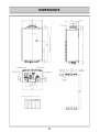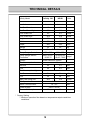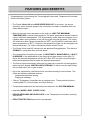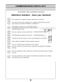
1
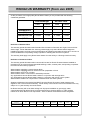
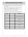
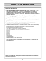
Installation and User Manual
Infinity 26i and HD50i
Continuous Flow Water Heater
Important.
Read these instructions carefully before attempting installation or use of
this appliance. All work must be carried out by competent persons.
RINNAI UK WARRANTY (from Jan 2005)
As the purchaser of this high quality Rinnai Water Heater you are provided with the following
conditional guarantee.
Standard Use
Heat Exchanger
All Other Parts
Parts
Labour
Parts
Labour
3 Years
1 Year
3 Years
1 Year
5 Years
1 Year
5 Years
1 Year
(26i)
Commercial Use
(HD 50i
Definition of Standard Use.
The warranty period allocated under Standard Use is based on Domestic and Light Commercial hot
water usage. Rinnai Standard Use warranty periods apply only where Rinnai water heaters are
installed in domestic and light commercial situations at operating temperatures below 650C and do not
include installations incorporating storage cylinders or building flow and return systems.
The warranty shall apply to any Rinnai water heater from the Infinity or HD range used in this way.
Definition of Commercial Use.
The warranty period allocated under Commercial Use are for Rinnai HD water heaters installed at
premises such as commercial and industrial buildings, cafes, caravan parks, and sporting complexes.
Commercial Use warranty applies to:
Water heaters supplying a central shower block
Water heaters supplying kitchens used for the bulk preparation of food.
Water heaters set to 650C or higher.
Water heaters used in commercial or industrial processes.
Any application that uses Rinnai water heaters in conjunction with storage tanks
Any application that uses Rinnai water heaters in conjunction with a flow / return system.
Water heaters installed as components of centralised bulk hot water systems.
Situations defined as Commercial Use MUST have the Rinnai HD range of water heaters to be
eligible for the Commercial Use warranty. Rinnai Infinity units used in Commercial Situations are only
subject to a 1 year warranty across the board.
No Rinnai warranty will cover faults arising from improper installation or gas supply, water
contaminants beyond defined limits, environmental factors, plumbing fittings, or other outside
influences of which Rinnai is not responsible. Service calls for these issues will be chargeable.
Description
pH
Maximum Recommended
Levels
6.5 - 9.0
Total Dissolved
Total Hardness
Solids (TDS)
600 mg/litre
200 mg/litre
Chlorides
Magnesium
Calcium
Sodium
Iron
300 mg/litre
10 mg/litre
20 mg/litre
150 mg/litre
1 mg/litre
2
CONTENTS
Warranty…………………………………
…………………………………………………2
Unpacking Rinnai Water Heater………… …………………………………….…………..3
Installation Instructions…………………… …………………………………………………4
Flue Requirements………………………... …………………………………………………8
Dimensions………………………………… ……………………………………………….10
Technical Details..………………………… ……………………………………………….11
Features and Benefits……………………. ……………………………………………….12
Important Information…………………….. ……………………………………………….13
Operation without Remotes……………… ……………………………………………….15
Temperature Controls…………………….. ……………………………………………….16
Testing……………………………………… ……………………………………………….27
Gas Pressure Setting…………………….. ……………………………………………….28
Dip Switch Setting………………………… ……………………………………………….30
Error Messages…………………………… ……………………………………………….32
Restarting the Rinnai Water Heater…….. ……………………………………………….34
Wiring Diagram……………………………. ……………………………………………….35
Diagnostic Points………………………….. ……………………………………………….36
Specification……………………………….. ……………………………………………….37
Service Contact…………………………… ……………………………………………….38
3
UNPACKING RINNAI WATER HEATER
• After unpacking the appliance check for damage, if the heater is damaged contact
your supplier immediately. Do not install a damaged appliance before checking
with your supplier.
• A heater accessories pack is inside the carton. One remote control is supplied
with the Infinity 26i. The HD50i does not come with controllers because it is a
commercial unit. It is compatible with them if they are required.
• Check that the appliance supplied is the correct gas type for the installation. Refer
to the data plate located on the left-hand side of the appliance.
• Remove the heater and the accessories from the carton, and check that all the
parts are included . The remote control cable is provided with spade connectors.
Description
Quantity
Remote Control Parts
Temperature controller MC-91-1A
1
Cable clamp
1
Cable Clamp
1
Spade connectors
5
Control cable 20 metres
1
Unit Mounting Fasteners
Clamp screw
1
Screw
5
Screw
5
4
INSTALLATION INSTRUCTIONS
IMPORTANT INFORMATION
1. Gas safety (Installation & Use) regulations 1998 are the ‘Rules in force’. In your
own interest and that of safety, it is law that all gas appliances are installed by
competent persons in accordance with the above regulations. Failure to install
appliances correctly could lead to prosecution. Other persons should NOT attempt to
install this equipment.
2. Unpack the appliance and check it carefully. If it appears to have any defects or
damage DO NOT INSTALL, contact your supplier.
3. This appliance is for normal hot water supply only and should not be used as pool or
spa water heater.
4. The heater must be installed in the vertical position with the gas and water
connections on the underside pointing vertically downward.
5. Installation must be carried out in accordance with the current issue of the following:
Building regulations issued by the Department of the Environment and
Building Standards (Scotland) Regulations.
I.E.E. Wiring regulations for electrical installations.
Gas safety (Installation and Use) Regulations current issue.
BS 5546
BS 5440
BS 6891
BS 5482
BS 6700
Local byelaws
Water regulations
Health and safety at work etc. Act 1974
Such other specifications and regulations that may supersede or complement the
above documents.
Please be sure that you are fully aware of your obligations and responsibilities
under these regulations.
5
INSTALLATION INSTRUCTIONS - POSITIONING
General Installation Information.
Internal Installations
The Rinnai Infinity 26i and the Rinnai HD50i are for internal installation in
conjunction with the Rinnai Power flue system.
The flue terminal clearances must be in accordance with the requirements of BS 5440.
Consideration should be given to other appliances, openings, and boundaries. Table and
Figure C.1 from BS5440-1:2000 is provided for your guidance.
The appliance must be mounted on a vertical wall or structure with the water and the gas
connections on the underside pointing towards the ground.
THIS APPLIANCE MUST NOT BE USED AS A DOMESTIC SPA OR SWIMMING
POOL HEATER.
Appliance Location.
The appliance should be placed as close as practicable to the most frequently used hot
water outlet point or points to minimise the delay time for hot water delivery. For
installations where the distance between the unit and hot water outlet points is
considerable, the appliance can also be fitted in a 'flow and return system' which
minimises the waiting time for hot water delivery. Alternatively, multiple appliances can
be strategically placed to service outlet points with minimal delay time. Contact Rinnai
for further information.
Location of the appliance flue terminal must be in accordance with the clearances shown
on page 8. Ensure that the flue terminal and hot water outlet connection cannot be
touched by children. The flue must be clear of obstructions and shrubbery.
The wall or structure on which it is mounted must be capable of supporting the weight of
the appliance (22 kg) and associated pipework. Ensure that suitable screws or bolts are
used to secure the water heater to the wall. Bracket and fixing hole locations are shown
on page 10. The top bracket has a keyhole slot so that the appliance can be hung on
one screw, and then the other fixings can be added to secure the unit.
The appliance must be in an accessible location. Sufficient clearances shall allow
access to, and removal of, all serviceable components. The unit should be mounted
high enough that the flue terminal will be above head height. If the terminal is below 2m
a guard must be put around it.
Multiple heater installations can be installed with the heaters manifolded together. The
minimum distance required between the heaters is based on the installation of the flue.
Refer to page 9 for more information on flue installation.
Although the flue and appliance have been specially designed to prevent condensation
in the flue for short runs (under 1.5m) care should be given to the placement of the
terminal to prevent risk in the unlikely event of condensation. Condensation water can
cause burns, and during winter could cause a slip hazard. It is the responsibility of the
installer to decide the best place for the terminal as every situation is different.
6
INSTALLATION INSTRUCTIONS - VENTILATION
General Information.
The unit must be installed by a competent, authorised person. It is the installer’s
responsibility to ensure that the unit has been installed to all current requirements.
The Rinnai Infinity 26i and HD50i are room sealed appliances. Ventilation requirements
of BS 5440 allow room sealed appliances to be installed in spaces and rooms, including
bedrooms, without ventilation.
If the Rinnai Infinity 26i or HD50i is installed in a compartment it must have the following
amount of permanent ventilation.
Ventilation from compartment to room:
540 cm2 at high level AND
540 cm2 at low level
Ventilation from compartment directly to outside:
270 cm2 at high level AND
270 cm2 at low level
The area given is the free area of the vent or equivalent free area for ventilators of more
complex design. Any space taken up by grille louvers should be subtracted from the
total area to find the free area of the vent.
Windows and doors can not be considered ventilation unless they are permanently fixed
in the open position.
Please refer to IGE/UP/10 Part 1. Edition 2 for further information or contact Rinnai UK.
7
INSTALLATION INSTRUCTIONS - CONNECTIONS
Water Supply.
Where the water supply pressure exceeds 12 bar, an approved pressure reducing
device is required at the inlet of the appliance. To achieve the rated flow a minimum
water supply pressure of 1.4 bar is required at the appliance inlet. The unit will operate
at lower supply pressures but the rated flow will not be achieved. Contact Rinnai for
'gravity fed' or 'low pressure' hot water installations.
Water pipe sizing and layout should be designed correctly to ensure the given water
flows from the appliance are available. All hot water pipework should be insulated to
optimise maximum performance and energy efficiency.
Water Connection.
Connect the hot and cold water supply pipes. An approved isolation valve and strainer
MUST be installed in the cold water inlet pipe. An approved isolation valve should be
installed in the hot water outlet pipe. There must be a union or release fitting on the
heater side of the isolation valves. A non return valve is not required unless dictated by
local regulations. A pressure relief valve should be installed in the pipework to
discharge safely into a suitable drain when the system has a flow and return, or tank.
Positions of the cold water inlet, hot water outlet and gas connections are shown on
page 11. All connections are ¾ inch BSP. This is NOT an indication of the pipe sizes
required.
If the heater is in a hard water area a suitable water conditioning device should be installed to prevent the build up of limescale within the heat exchanger. Heat exchangers
damaged by scaling are not covered by the manufacturers guarantee. Guidelines are
given below. If the local water exceeds these values the heater must be protected.
Description
pH
Maximum Recommended
Levels
6.5 - 9.0
Total Dissolved
Total Hardness
Solids (TDS)
600 mg/litre
200 mg/litre
Chlorides
Magnesium
Calcium
Sodium
Iron
300 mg/litre
10 mg/litre
20 mg/litre
150 mg/litre
1 mg/litre
Gas Connection
Check pipe sizing required for the heater input. The heat input for the Infinity 26i and
HD50i is 54 kW. Refer to BS6891 (Natural Gas) and BS5482 (Propane) for guidance on
correct pipe sizing calculation.
Check that the size of the gas meter and pipework will be sufficient for all appliances on
the main. Sufficient gas must be available at the appliance if correct operation is to be
expected. An approved gas isolation valve must be fitted at the gas inlet. A union or
release fitting should be installed after the isolation valve.
Electrical Connection.
The appliance must be earthed. The appliance is suitable for 230VAC – 50Hz mains
only and all wiring must be carried out to the I.E.E regulations latest edition. The heater
electrical supply must be provided with a fused (3A) local isolator with a contact
separation of 3mm minimum on all poles for servicing. Observe polarity and ensure that
wiring is correctly restrained.
8
FLUE REQUIREMENTS - POSITIONING
Dimension Terminal Position
Distance
A
Directly below an opening, air brick, opening windows, etc.
300mm
B
Above an opening, air brick , opening window, etc.
300mm
C
Horizontally to an opening, air brick , opening window, etc.
300mm
D
Below gutters, soil pipes or drain pipes.
75mm
E
Below eaves.
200mm
F
Below balconies or car port roof.
200mm
G
From a vertical drain pipe or soil pipe.
150mm
H
From an internal or external corner.
200mm
I
Above ground, roof or balcony level.
300mm
J
From a surface facing the terminal.
600mm
K
1200mm
L
From a terminal facing a terminal
From an opening in a car port. ( e.g. door, window) into a dwelling
1200mm
M
Vertically from a terminal on the same wall.
1500mm
N
Horizontally from a terminal on the same wall.
300mm
O
From the wall on which the terminal is mounted
N/A
P
From a vertical structure on the roof.
N/A
Q
Above an intersection with roof.
N/A
9
FLUE REQUIREMENTS - INSTALLING
General.
The flue must be installed in accordance with:
Manufacturers Installation Instructions
British Standards including BS5440
Gas Safety (Installation and Use) Regulations
IGE/UP/10 Part1 Edition 2.
Building Regulation J
The flue must be installed by a competent, authorised person. It is the installer’s
responsibility to ensure that the unit has been installed to all current requirements.
The Rinnai Infinity 26i and HD50i are internal units which may only be installed with the
approved Rinnai Infinity and HD flue kit provided. These instructions only apply to
coaxial Rinnai Flues with stainless steel inner pipe, and white plastic outer pipe. These
instructions do not apply to Rinnai Flues with stainless steel single skin or stainless steel
coaxial flue. If in doubt contact Rinnai UK.
The required clearance of the flue terminal is shown on page 9. When multiple units are
installed together there must be enough of a gap to satisfy the requirements of the
regulations. Under current regulations the heaters should have at least an 100mm gap
between them. The flue terminal should be over 2m from ground level whenever
possible. For lower installations a terminal guard cage must be installed.
The Rinnai Infinity 26i and HD50i comes standard with a horizontal flue kit consisting of
a 90 degree adapter bend and 700mm length of flue pipe with wall terminal and wall
plate. If the installation requires a vertical flue kit or any additional pipe or bends they
must be ordered separately. 45 degree bends are available.
Vertical Termination.
If the flue is to terminate vertically the maximum flue length is 9m. At that length three
900 bends are permitted. For an additional 900 bend 2m must be subtracted from the
maximum length (1m for each 450 bend.) No more than four 900 bends are permitted.
Horizontal Termination
If the flue is to terminate horizontally the maximum flue length is 15m. 2m must be subtracted for each 900 bend, including the 900 adapter, up to a maximum of four 900 bends
(Subtract 1m per 450 bend.) With four 900 bends the maximum length would be 7m.
Take care when fitting the flue pieces together not to damage the seals. The use of soft
liquid soap such as hand soap will allow the pieces to slide together. Do not use hard
detergents as they may damage the seals. When cutting sections of the flue remove all
burrs and file a slight chamfer on to the outer edge to prevent damage to the seals.
Flue pipes must include a condensate drain if the total flue height exceeds 1.5m. There
is a special condensate drain collector piece available through Rinnai UK. For flue runs
requiring a drain the horizontal sections should slope towards the appliance, and the flue
should be bracketed to prevent sagging. If the flue run is less than 1.5m it should slope
gently to the outside to prevent ingress of rain.
The drain pipe should be run in 22mm PVC, uPVC, or ABS pipe, copper is not recommended. The drain pipe MUST be trapped. A trap with pipe is available from Rinnai UK.
10
DIMENSIONS
11
TECHNICAL DETAILS
Infinity Model
Units
Infinity 26i
HD50i
Internal
Internal
Nat Gas Press Low
1.9
1.9
mbar
Nat Gas Press High
8.5
8.5
mbar
LPG Press Low
2.3
2.3
mbar
LPG Press High
10.8
10.8
mbar
Height
600
600
mm
Width
350
350
mm
Depth
224
224
mm
Weight
22
22
kg
Flue System
Direct Forced Vent
Installation
Temp. Range Controllers
37C - 55C
37C - 65C
deg C
Temp. Range without
Controllers
40,43,50,55*,
60,65,75
40,43,50,55,
60,65*,75,85
deg C
Ignition
Direct Electronic Ignition
Gas Consumption Low
Nat Gas
4.4
4.4
kW
LPG
4.4
4.4
kW
Nat Gas
54
54
kW
LPG
54
54
kW
19.6
19.6
Gas Consumption High
Max Flow raised 33C
Min Operation Flow
2.4**
Water Pressure Nom.
L/min
1.4 - 8.3
Power Supply
L/min
bar
230 V / 50 Hz
Electric Consumption
80
80
Watts
* Factory Setting
** Minimum operation flow based on temperature setpoint and inlet
conditions.
12
FEATURES AND BENEFITS
Congratulations on purchasing the Technologically Advanced, Temperature Controlled,
Rinnai Hot Water System.
• The Rinnai Infinity 26i and HD50i NEVER RUN OUT of hot water. As long as
electricity, water, and gas supplies are connected, hot water is available when hot
water taps are open.
• Built into the main micro-processor is the facility to LIMIT THE MAXIMUM
TEMPERATURE of the hot water supplied. The water temperature may be limited to
various maximum temperatures. This is particularly useful when the hot water unit is
installed where young children or the infirm may be using the hot water. The Infinity
26i is delivered with a preset temperature of 550C, and the HD50i is delivered with a
preset temperature of 650C. If required, the temperature limits can be changed by an
authorised person. For further information, please contact Rinnai.
• The Rinnai Infinity and HD internal units are powered flue appliances. This makes it
COMPACT, saving both floor and wall space.
• The temperature of outgoing hot water is CONSTANTLY MONITORED by a BUILT-
IN SENSOR. If the temperature of the outgoing hot water rises to more than 3°C
above the selected temperature the burner is shut OFF and only turned ON again
when the temperature falls to below the selected temperature.
• The burner lights automatically when the hot water tap is opened, and extinguishes
when the tap is closed. IGNITION IS ELECTRONIC, so there is no pilot light. When
the hot water tap is off, no gas is used.
• Up to four temperature controllers can be mounted remotely from the heater. This
offers the following additional features:
Localised temperature setting.
Diagnostic message.
• ‘Deluxe’ Temperature Controllers are an optional extra. These provide functions
including Bath Fill, Voice Prompt, and Clock Setting.
• Temperatures selected at the controllers are retained in the SYSTEM MEMORY.
• Operating NOISE LEVEL IS VERY LOW.
• ERROR MESSAGES ARE DISPLAYED on the Temperature Controllers, assisting
with service.
• FROST PROTECTION device built in as standard.
13
IMPORTANT INFORMATION
Excessively hot water is dangerous, especially for young children and the infirm. The
water heater allows you to control the temperature of your hot water to safe levels.
Water temperature over 50ºC can cause severe
burns instantly or even death from scalding.
Children, disabled and the elderly are at the
highest risk of being scalded by excessively hot
water.
Always test the temperature of the water before
bathing or showering.
Burns from hot water taps can result in very
severe injuries to young children.
Hot water at 65°C can severely burn a child in less
than half a second. At 50°C it takes five minutes.
Burns can occur when children are exposed
directly to hot water or when they are placed into a
bath which is too hot.
Do stay with children whenever
they are in the bathroom.
Do take them out of the bathroom if
you need to answer the phone or
door.
Do test the temperature of the water
with your elbow before placing your
child in the bath.
DO
• Consider child—resistant taps
or inexpensive tap covers,
both of which prevent a child’s
hand from turning on the tap.
• Consider reducing the
Do make sure that the tap is turned
off tightly.
Do consider setting your Rinnai
Infinity or HD50i at a maximum
temperature of 500C.
Do install a child proof tap cover
OR,
Do install a child resistant tap.
DO
NOT
Do not leave a toddler in the care of
another small child. The older child
may not have safely set the temperature.
14
temperature of the water supplied to the hot tap to 500C.
This approach can be extremely
valuable because it requires a
one time action for a long term
reduction in risks of scalds.
This type of automatic protection
is important during times when a
parent or carer has been
distracted.
IMPORTANT INFORMATION
Always check water temperature before
use.
Hot water may go out without warning at
low water flows.
OFF
Refer to warning about hot water on
page 14 for important safety information.
The Infinity 26i and HD50i control the
water temperature automatically. For
high temperatures it may reduce the flow.
The water from the hot tap may be
reduced after the temperature shown on
the remote control is raised. The water
flow may also vary with the temperature
of the incoming water supply.
If freezing temperatures
are expected, turn off the
water and gas, and
drain the water
heater.
1. Water Off
2. Gas Off
3. Drain Water
If the power is left on the
Automatic Frost Protection
will prevent the unit from
Freezing. Frost protection
is standard on all units.
Keep flammable materials, trees, shrubs,
chemicals etc. away from the flue outlet.
Do not touch the unit cover or the flue
outlet. Do not insert objects into the flue
outlet.
On cold days steam may be discharged
from the flue outlet. This is normal, do
not be alarmed. It does not indicate a
fault.
15
OPERATION WITHOUT REMOTES
Rinnai Infinity and HD products have no pilot light and when installed without
Temperature Controllers, the appliance will operate automatically as soon as a hot water
tap is opened.
The burner ignites with electronic ignition and the flame extinguishes as soon as water
flowing through the appliance stops.
Turn On by opening the hot water tap
Rinnai Infinity water heaters without controllers are factory pre-set to a temperature limit
of 55°C. Rinnai Heavy Duty (HD) series are factory pre-set to a temperature limit of
65°C. Other limits, lower or higher, are available on request for both the Infinity and HD
range. Temperature controllers are available that allow precise digital temperature
control. Higher temperatures may be necessary for circulation loop systems.
Controllers can be easily added at any time after installation.OTE
16
TEMPERATURE CONTROLS - GENERAL
When deciding on the best position for the temperature controls, the following points
should be taken into account.
• Fit the controls out of reach of children (suggested height from the floor 1.5m.)
• Avoid positions where the controllers will become hot. Do not fit them near stoves or
ovens, or above radiators or heaters.
• If possible, avoid exposure to direct sunlight or positions where bright lights will make
the digital display difficult to read.
• Position away from areas where the controller will be prone to splashing by cooking
products such as oils and fats.
• The temperature controllers are water resistant, however they should be positioned
away from areas where direct or persistent splashing could occur.
• Refer to the I.E.E electrical wiring regulations current edition for location requirements
in shower and bath areas.
• The cables to the temperature controller carry only 12VDC (extra low voltage.)
• When using more than one temperature controller the signal cable should be run in
parallel. That is, from controller to controller to heater, or from each controller to the
heater. Do not wire the controllers in series.
The installation in every application will vary, therefore the temperature controller cable
has been provided so that you may cut the length accordingly and fit the spade
connectors, ensuring a good connection.
Cables are simply ‘piggy-backed’ at the water heater or at the primary temperature
controller. Polarity is not important when connecting the cables, either colour wire can
be connected to either terminal at both the heater or primary temperature controller. If
more cable is needed any cable with similar specification to the cable supplied with the
controller can be used. Maximum length is 50 metres.
17
TEMPERATURE CONTROLS - INSTALLATION
Universal Temperature Controller
MC-91-1A
1. Determine the most suitable position for
the temperature controller.
2. Drill 3 holes in the wall as shown in fig 1,
one for the cable and two for the
securing screws. Ensure holes are
drilled deep enough. Fit wall plugs if
needed. (ensure controller is level.)
3. Run the cable provided through the hole
in the wall-ensuring that the end fitted
with the connector is nearest the
controller. (fig 2.)
4. Remove the face plate from the
controller using a flat screwdriver. Take
care not to damage the cover (fig 3.)
5. Connect the cable to the temperature
controller.
6. Fix the controller to the wall and fasten
with the phillips head screws as shown
in (fig 4.)
7. Remove the protective plastic film from
the controller face as shown in (fig 4.)
8. Replace the face plate.
NOTE
18
TEMPERATURE CONTROLS - INSTALLATION
Connecting One or Two Controllers
1. Isolate the power supply.
2. Remove the front cover from the Appliance (4
screws) fig. 1.
3. Thread the cable through the cable access hole at
the base of the appliance.
4. Connect the spade connectors to the terminals
marked "Remote Control" on the printed circuit
board (fig.2). Polarity is not important. Either wire
colour can be connected to either terminal.
5. Replace cover of the Appliance. Ensure that the
special earth screw is placed at the bottom right
hand corner for earthing purposes.
Connecting Three Controllers
1. Isolate the power supply.
2. Remove the front cover from the Appliance (4
screws) fig.1.
3. Thread the cables through the cable access hole
at the base of the appliance.
4. Cut the spade connectors from two controller
cables (4 connectors should be cut off) and
discard. Connect the wires and terminate into
two new spade connectors as shown in fig. 3.
5. Thread the 3 cables through the cable access
hole at the base of the appliance. Connect the
4 spade connectors to the terminals marked
“Remote Control" on the printed circuit board
(fig.2). Polarity is not important. Either wire
colour can be connected to either terminal.
6. Replace cover of the Appliance. Ensure that the
special earth screw is placed at the bottom right
hand corner for earthing purposes.
Connecting Four Controllers
1. Isolate the power supply.
2. Remove the front cover from the Appliance (4
screws) fig.1.
3. Cut the spade connectors from all four controller
cables to be connected to the appliance (8
connectors should be cut off) and discard.
Connect the wires from two remotes and
terminate into two new spade connectors as
shown in fig. 3.
4. Repeat for remaining two remotes.
5. Thread the 4 cables through the cable access
hole at the base of the appliance. Connect the 4
spade connectors to the terminals marked
“Remote Control" on the printed circuit board
(fig.2). Polarity is not important. Either wire colour
can be connected to either terminal.
5. Replace cover of the Appliance. Ensure that the
special earth screw is placed at the bottom right
hand corner for earthing purposes.
19
TEMPERATURE CONTROLS
The purpose of a Temperature Controller is to enable the user to have complete control
over the hot water supply. Used correctly, the hot water unit will supply hot water at the
temperature selected, even when the water flow is varied, or when more than one tap is
used. Adjustments to the operation of your hot water unit can be made with any of the
Temperature Controllers. Each Temperature Controller can be individually programmed.
Up to four Universal and Deluxe Temperature Controllers can be fitted with the Infinity
26i and HD50i. Universal Controllers allow temperature selection only and come as
standard with the water heaters. Deluxe Temperature Controllers are an optional extra.
These controllers have temperature selection, bath fill, voice recognition, and time clock
functions. When more than one Universal Controller is used one may be set as the
Master Controller to allow higher temperatures.
Various water temperatures (°C) can be selected as follows:
Universal Controller:
37, 38, 39, 40, 41, 42, 43, 44, 45, 46, 48, 500C
Master Universal Controller:
37, 38, 39, 40, 41, 42, 43, 44, 45, 46, 48, 50, 55°C ( 60, 65°C HD )
Deluxe Bathroom Controller:
Hot Water Delivery: 37, 38, 39, 40, 41, 42, 43, 44, 45, 46, 48, 50°C
Bath fill Delivery: 37, 38, 39, 40, 41, 42, 43, 44, 45, 46, 47, 48°C
Deluxe Kitchen Controller:
37, 38, 39, 40, 41, 42, 43, 44, 45, 46, 48, 50, 55°C ( 60, 65°C HD )
If a temperature 43°C or higher is selected on any controller and this temperature is then
decreased to below 43°C and increased again whilst the water is running, the maximum
selectable temperature will become 43°C. This provides additional safety for the
consumer.
Suggested temperatures are:
Kitchen 50°C - 65°C*; Shower 39°C - 43°C; Bath fill 39°C - 45°C
* This temperature may not be available on all installations.
These temperatures are suggested starting points for selection. You may find higher or
lower temperatures are more comfortable. Maintaining lower temperatures helps to save
energy. To obtain water temperatures lower than 37°C simply add cold water.
Up to four controllers can be used for one Infinity 26i or HD50i. When multiple
temperature controllers are used they allow the temperature to be set from various
locations by pushing the transfer button which gives that controller priority over the
system. The temperature selected by the controller with priority will be available to all
outlets.
20
TEMPERATURE CONTROLS - OPERATING
Remote temperature controllers are a feature that provides control over the water
temperature. Rinnai Infinity and HD water heaters can be operated with 1, 2, 3, 4 or no
temperature controllers. The Universal controller MC-91-1A comes as standard with all
Infinity water heaters, and are optional for the HD range.
NOTE:
Each time a button is pressed, a BEEP will sound.
The BEEP sound can be muted by depressing the Temperature Controller Up and Down
buttons simultaneously for more than 3 seconds.
This can be done for each Temperature Controller.
To return to original settings, repeat this step.
21
TEMPERATURE CONTROLS - OPERATING
Using 1 Universal Temperature Controller.
Press the On/Off button on the temperature controller.
The ON indicator will glow on the Temperature Controller.
This indicates that the heater is ready to supply hot water
when a tap is opened.
Adjusting Temperature
Simply press the Hot Water Temperature Up or Down arrow
button until the desired temperature is displayed on the
digital display.
To operate the heater, simply turn any hot water tap on. This
will automatically light the burner providing hot water. The
red In Use indicator will glow on the temperature controller.
Caution: Always check water temperature before use.
Note:
With the hot water tap open and a temperature of 430C or higher selected,
if the temperature is decreased to below 430C, and then raised again the
maximum available temperature will be 430C. For safety reasons
temperature ‘priority’ cannot be transferred between controllers when a
hot water tap is open.
22
TEMPERATURE CONTROLS - OPERATING
Using 2 or more Universal Temperature Controllers.
Switching the system ON.
The hot water system and all controllers can be
switched ON and OFF from any controller by pressing
the On/Off button as shown. When the system is
turned ON the water temperature display will be lit.
During normal operation the system is left ON. Do
not push the On/Off button when water is running.
Using hot water.
Ensure the system is switched On by verifying the
temperature display is lit. Ensure the controller has
priority by verifying the Transfer LED indicator is lit. If
it is not then press the Transfer button once. This
gives the local controller priority of temperature over
the system.
Select the desired temperature using the Hot water
temp. buttons. The selected temperature will be
displayed on all controller displays. This is the water
temperature which will be supplied from the heater.
Bathroom temperatures should be no more than 500C.
Open the hot water tap. The appliance
will be activated and the In Use
indicator will be lit.
23
TEMPERATURE CONTROLS - OPERATING
Using 4 Universal Temperature Controllers.
You will need to activate the fourth controller.
STEP 1:
On the Master controller press and hold the Transfer and On/Off buttons
simultaneously (see fig 2.) until a “beep” is heard (approx. 5 seconds)
STEP 2:
Check that the display on all Four controllers is lit
and displaying a temperature when switched on. If
any ONE of the controllers displays two dashes (see
fig 1.) in the display repeat STEP 1.
Note:
If the master controller is replaced, repeat STEP 1 above for the new controller.
24
TEMPERATURE CONTROLS - OPERATING
Using High Temperature Display Controllers.
You will need to program the Master controller if you want to display and use
temperatures over 500C. Programming only needs to be done on Master universal
controllers; other universal controllers will not allow this, and Deluxe Kitchen Controllers
are supplied already programmed to allow high temperatures. Temperatures in
bathrooms should never exceed 500C.
STEP 1:
On the Master controller press and hold the Transfer and On/Off buttons
simultaneously (see fig 2.) until a “beep” is heard (approx. 5 seconds)
STEP 2:
When the Master controller is switched on it should be possible to select
temperatures higher than 50ºC. If not repeat STEP 1.
Note:
If the master controller is replaced, repeat STEP 1 above for the new controller.
25
TEMPERATURE CONTROLS - OPERATING
To turn off your hot water system.
During normal operation the system is left on.
To turn the system off simply press the On/Off
button on any temperature controller (where
fitted). This will shut the water heater down
completely including the temperature controller
digital display.
The on indicator will go out.
If hot water taps are opened when the Rinnai
Infinity is off, cold water will flow from the taps.
If the system is to be left off over the winter be
sure to drain it down if there is a possibility of
freezing temperatures.
Additional safety features.
Whilst the hot water tap is open, the following
safety features apply:
• Temperature selection cannot be transferred.
0
• If a temperature of 43 C or higher selected,
and the temperature is decreased to below
430C, and then raised again the maximum
available temperature will be 430C.
• Other controllers are unable to change the
delivery temperature of the water.
Note
The temperature of the outgoing water is constantly monitored by a built in
sensor. If the temperature of the outgoing hot water rises to more than 3ºC
above the selected temperature shown on the digital display, or the preset
limit if controllers are not fitted, the burner will automatically go out. The red
operation indicator will also go out. The burner will ignite again once the
outgoing hot water temperature falls to that shown on the digital display (or
the pre-set limit of the Rinnai Infinity heater).
26
TEMPERATURE CONTROLS - INFORMATION
Do not push the On/Off button on the
Master controller after transferring priority
of temperature selection to a Secondary
controller as the system will shut down.
Temperature priority can not be switched
to another controller when the water is
flowing through the water heater.
500C
Do Not Turn OFF
the Master
Controller
Controller 1
in use
If a temperature higher than 50ºC has
been selected on the Master controller
and priority of temperature selection is
transferred to another controller (or it is
turned off), then back again (or turned on
again), the temperature on the Master
controller will automatically drop to 50ºC.
If the set point is less than 500C it will not
alter. This is a safety feature.
Master
Controller
Another
Controller
Controller 2
cannot take
priority
Do not clean the remote control with
solvents or detergents. Use only a soft
damp cloth.
Master
Controller
If a temperature higher than 420C has
been selected on the Universal controller and priority of temperature selection is
transferred to another controller (or controller is turned OFF), then back again (or
turned ON again), the temperature will
automatically drop to 420C. If the set
point is less than 420C it will not alter.
This is a safety feature.
Depending on the weather conditions
and the length of the pipe between the
heater and the tap in use, there may be a
variation between the temperature displayed at the controller and the temperature at the tap.
480C
Universal
Controller
27
Another
Controller
Universal
Controller
TESTING
1. Purge gas, hot water and cold water supply lines before making the final connection
of the water heater. Swarf in either the gas or water supplies may cause damage.
2. Turn on gas and cold water supplies.
3. Test for water leaks and gas escapes near the unit.
4. Isolate gas and electric supply. Remove test point screw located on the inlet gas
valve connection inside the heater and attach pressure gauge.
5. Turn the power on at the switch and turn on gas. Warning: There are 230V AC live
supplies inside the heater.
6. If remote controllers are fitted, turn the controller on, select the maximum delivery
temperature and open ALL available hot water outlets. If remote controllers are not
fitted, simply open all available hot water outlets. (CAUTION: Ensure building
occupants do not have access to hot water outlets during this procedure).
7. The gas pressure check must be carried out with all other appliances on the same
main operating at maximum capacity to ensure that there is sufficient gas pressure.
8. With all other appliances operating the pressure at the test point on the inlet to the
gas valve should read 20 mbar for Natural Gas. For LPG (Propane) the pressure
should be 37 mbar. If the pressure is lower, the gas supply is inadequate and the
water heater will not operate to specification. Check gas meter, regulator and
pipework for correct operation/sizing and rectify as required. Note that the gas
regulator on the appliance is electronically controlled and factory pre-set. Under
normal circumstances it does not need adjustment during installation.
9. Close hot water outlets.
10.Inspect and clean the strainer and the filter located on the cold water inlet pipe. This
procedure may need to be repeated to ensure the strainer remains clear.
11.If temperature controllers are fitted, it is necessary to test their operation through the
complete range of functions.
12.Confirm the hot water delivery temperature using a thermometer. If controllers are
fitted, compare the measured value to the set point.
13.After testing is completed, explain to the user the functions and operation of the
water heater and temperature controllers.
28
GAS PRESSURE SETTING
The working gas pressure on the water heater is electronically controlled and factory set.
Under normal circumstances it does not require adjustment during installation. Perform
this procedure only if the unit is not operating correctly and all other possible causes for
incorrect operation have been eliminated. Contact Rinnai UK before
attempting to alter the gas pressure. Failure to do so could void
the warranty.
1. Turn 'OFF' the gas supply.
2. Turn 'OFF' 230V power supply.
3. Remove the front cover from the appliance.
SW1
SW2
4. Check gas type switch no.1 of SW2 is in the
correct position for the type of gas (Nat. or
LPG) you are using. (SW2 is bottom set of
switches.)
off
on
SW2
1 -Nat. Gas
2
3
4
off
on
SW2
1 -LPG
2
3
4
* On is in the forward position, Off is in the back
position. Pull the switch toward you to put it
in the on position.
5. Attach pressure gauge to burner test point. (fig. 2)
6. Turn 'ON' the gas supply.
7. Turn 'ON' 230V power supply.
8. If remote controllers are fitted, turn the unit
'ON' at the master controller, select a
maximum delivery temperature and open a
hot water tap fully. (CAUTION: Ensure
building occupants do not have access to
hot water outlets during this procedure.)
off
on
9. Set the Rinnai Infinity to 'Forced Low'
combustion by setting No. 7 dipswitch of the
top set of dip switches (SW1) to 'ON'. (fig 3)
10.Check the burner test point operating
pressure.
fig. 3
29
SW1
1
2
3
4
5
6
7
8
GAS PRESSURE SETTING
11. Remove rubber access plug and adjust the
regulator screw on the modulating valve (fig. 4) as
required to the pressure below. Replace rubber
access plug.
N.G
1.9 mbar
LPG
2.3 mbar
12. Set the Rinnai Infinity to 'Forced High'
combustion by setting no. 7 and no. 8
dipswitches of the top set of switches (SW1) to
'ON'. (fig.5) Ensure maximum water flow.
off
on
13. Check the burner test point pressure.
14. Adjust the high pressure potentiometer on
the Printed Circuit Board above SW1 (fig. 6) to
the pressure shown below. The potentiometer
is very sensitive, turn no more than a few
degrees at a time; then let the pressure settle
down before turning it more.
N.G
8.5 mbar
LPG
10.8 mbar
15. IMPORTANT: Set dip switch no. 7 and no. 8
on the top set of switches (SW1) to 'OFF'
to return the appliance to 'Normal' combustion.
SW1
1
2
3
4
5
6
7
8
fig. 5
High Press.
Potentiometer
16. Close hot water tap.
17. Turn OFF the gas supply and 230V power
supply.
fig. 6
18. Remove pressure gauge, and replace sealing
screw
19. Turn 'ON' the gas supply and 230V power
supply.
20. Operate unit and check for gas leaks at test
point.
21. Replace the front cover of the appliance.
30
CAUTION
DIP SWITCH SETTING
Dip Switch Positions Explained
OFF ON SW1
1
2
3
4
5
6
7
8
-
Computer Programming
Temperature
Temperature
Temperature
Temperature
Temperature
Combustion
Combustion
OFF ON SW2
1
2
3
4
-
Gas Type
Not in Use
Computer Programming
Not in Use
LEGEND:
Black Section indicates
position of dip switch.
OFF ON
OFF ON
OFF
ON
Dip Switches Explained
GAS TYPE
LPG
OFF ON SW2
1
off
2
3
4
COMBUSTION
NAT GAS
NORMAL
OFF ON SW2
1 on
2
3
4
OFF ON SW1
7 off
8 off
OFF ON SW1
7 on
8 off
COMPUTER PROGRAMMING
OFF ON SW1
1
2
3
4
5
6
7
8
FORCED LOW
Computer programming
Switches and Not in Use
Switches are always in the
OFF position for the
Infinity 26i and HD50i.
OFF ON SW2
1
2
3
4
31
FORCED HIGH
OFF ON SW1
7
8 on
DIP SWITCH SETTING
Infinity 26i and HD50i
Temperatures - With or Without Remotes Connected
off
on SWI
1
2
3
4
5
6
7
8
40 deg C
off
on SWI
1
2
3
4
5
6
7
8
43 deg C
off
on SWI
1
2
3
4
5
6
7
8
50 deg C
HD50i only
Temperatures - Remotes Connected
off on SWI
off on SWI
off on SWI
1
1
1
2
2
2
3
3
3
4
4
4
5
5
5
6
6
6
7
7
7
8
8
8
60 deg C
65 deg C
75 deg C
off
on SWI
1
2
3
4
5
6
7
8
60 deg C
off
on SWI
1
2
3
4
5
6
7
8
55 deg C
(factory setting)
If the remote was
accidentally
disconnected the unit
would revert to 55C
HD50i only
Temperatures - Remotes Not Connected
off on SWI
off on SWI
off on SWI
1
1
1
2
2
2
3
3
3
4
4
4
5
5
5
6
6
6
7
7
7
8
8
8
65 deg C
75 deg C
85 deg C
(factory setting)
32
ERROR MESSAGES
Rinnai water heaters have the ability to check their own operation continuously. If a fault
occurs, an error code will flash on the Digital Display if you have temperature controllers
installed. This assists with diagnosing the fault, and may enable you to overcome a
problem without a service call. Please quote the code displayed when enquiring about
service.
Code
Displayed
Fault
Remedy
-
Noticeable reduction in water
flow
Inlet water filter needs to be cleaned.
03
Power interruption during
operation
(water will not flow when power
returned)
Turn off all hot water taps and
circulating pumps.
Press ‘On/Off’ twice
10
Not enough combustion air
Check for physical blockages around
air intake or exhaust. Check
combustion fan.
11
No Ignition / Gas supply
Check gas valves, gas supply and
ignition unit.
12
Flame failure / Earth Leakage
Check gas valves and gas supply.
Check flame rod.
Check earth wire lead.
Check remote control.
14
High flame safety device
Service Call
16
Over temperature warning
Service Call
32
Outgoing water temperature
sensor faulty
Service Call
33
Heat exchanger outlet sensor
faulty
Service Call
34
Combustion Air Temperature
Sensor Faulty
Service Call
52
Gas modulating valve faulty
Service Call
61
Combustion fan failure
Service Call
65
Water flow control faulty
(does not stop flow properly)
Service Call
71
Micro-processor failure
Service Call
72
Flame rod circuit error
Service Call
* In all cases, you may be able to clear the Error code by turning the hot water tap OFF, then ON
again. If this does not clear the error, try pushing the On/Off button OFF then ON again. If the Error
Code still remains contact Rinnai or your nearest service agent for advice.
** Faults caused by insufficient gas/water supply or gas/water quality and installation errors are not
covered by the manufacturer’s guarantee.
33
ERROR MESSAGES
Troubleshooting without controllers
If you have not installed temperature controllers and experience the following
symptoms, please carry out the suggestions below. If symptoms continue, please
contact Rinnai for advice.
Fault
Remedy
Heater does not attempt Check the power is on at the heater.
to start at all.
Check the cold water valve supplying the heater is open.
Heater starts then shuts
down immediately.
Check the power is on.
Check the gas valve at the heater and at the gas meter is fully open.
Open the hot water tap fully.
Heater starts then the
water goes cold.
Check the power is on.
Open your hot water tap further or try another hot outlet.
NOTE: Faults caused by insufficient gas/water supply or gas/water quality and
installation errors are not covered by the manufacturer’s guarantee.
Installations with circulation pumps
With temperature controller fitted.
If you have an installation using a secondary circulation pump this must be
switched off so that there is no flow through the heater when starting or after a
power failure. If the pump is running the unit will not operate (no display on the
controller). Isolate pump then start heater before restarting pump. This is a safety
feature.
The pump should also be fitted with a thermostat to prevent the return temperature
reaching the heater set point temperature.
Without temperature controller fitted.
The heater should automatically reset and provide water at the temperature set by
the internal limit switches.
34
RESTARTING THE RINNAI WATER HEATER
Following a power cut the heaters should be restarted in this manner.
Standard system.
Single or multiple water heaters without remote controllers.
The heaters will automatically reset without any user involvement.
Single or multiple water heaters with remote controllers.
The heaters will be required to be switched on using the ON/OFF button on a remote
controller. Ensure that all taps/water outlets are closed and no water is flowing through
heaters.
Hot water system incorporating secondary recirculation pump.
Single or multiple water heaters without remote controllers.
The heater(s) will automatically reset without any user involvement.
Single or multiple water heater(s) with remote controller(s).
To reset the heaters follow the steps.
1. Turn off all hot water taps.
2. Turn off supply to secondary circulating pump or alternatively, if heater and pump
are fed from the same electrical supply, isolate pump flow.
3. Turn on heater at remote control.
4. Select required temperature.
5. Switch on supply to secondary circulating pump or open valve on pump flow.
The heater will now be ready to supply water at the set temperature.
If following the above procedure does not reset the heater switch it on and off at its main
supply, and then go through these steps again. If heater is still not working call your local
service agent or Rinnai for assistance.
35
WIRING DIAGRAM
MC-91-1A
MC-91-1A
36
DIAGNOSTIC POINTS
Diagnostic Points- To be read in conjunction with the wiring diagram.
37
SPECIFICATION
Model………………………………………………..…....………….....Infinity 26i and HD50i
Installation…………………………………………...………...……... Internal location only
Fuel…………………………………………………..….……………...Natural Gas or LPG *
Control………………………………………………….……………...…….….…..Modulating
Input…………………………………………………...…..……….……………....4.4 to 54 kW
Exhaust type…………………………………………...…………….....Forced Draught Flue
Ignition………………………………………………...…………….………………..Electronic
Burner……………………………………………………...…………………....Stainless steel
Weight…………………………………………………...……….……………..…..………22Kg
Water flow rate ………………………………………..……………….…...2.4** to 32L/min
Minimum operating water pressure…………………..……….………..…..……….1.0 Bar
Connections
Gas…………………………………………………………...….………………….…….3/4BSP
Water Inlet………………………………………….………...……………….…….……3/4BSP
Water outlet…………………………………….………...………………………….…..3/4BSP
Electrical Supply…………………………….…………..…………….….230V AC 50Hz 1ph
* Separate models available for Natural gas or LPG fuel.
** Minimum flow rate based on temperature setpoint and inlet conditions.
Rinnai are continually updating and improving products and reserve the right to
alter model specifications without prior notice.
38
SERVICE CONTACT
Rinnai UK LTD.
9 Christleton Court
Manor Park
Runcorn
Cheshire
WA7 1ST
Tel. 01928 531870
Fax. 01928 531880
E-mail. [email protected]
Web.
www.rinnaiuk.com
REU-V2632FFU 28/1/5 rev3
39
COMMISSIONING CHECK LIST
40